EP0022411B1 - Verbesserungen in Schaltgetrieben, insbesondere zum Einlegen des Rückwärtsganges - Google Patents
Verbesserungen in Schaltgetrieben, insbesondere zum Einlegen des Rückwärtsganges Download PDFInfo
- Publication number
- EP0022411B1 EP0022411B1 EP19800401016 EP80401016A EP0022411B1 EP 0022411 B1 EP0022411 B1 EP 0022411B1 EP 19800401016 EP19800401016 EP 19800401016 EP 80401016 A EP80401016 A EP 80401016A EP 0022411 B1 EP0022411 B1 EP 0022411B1
- Authority
- EP
- European Patent Office
- Prior art keywords
- sleeve
- gearwheel
- sliding
- frusto
- pinion
- Prior art date
- Legal status (The legal status is an assumption and is not a legal conclusion. Google has not performed a legal analysis and makes no representation as to the accuracy of the status listed.)
- Expired
Links
Images

Classifications
-
- F—MECHANICAL ENGINEERING; LIGHTING; HEATING; WEAPONS; BLASTING
- F16—ENGINEERING ELEMENTS AND UNITS; GENERAL MEASURES FOR PRODUCING AND MAINTAINING EFFECTIVE FUNCTIONING OF MACHINES OR INSTALLATIONS; THERMAL INSULATION IN GENERAL
- F16D—COUPLINGS FOR TRANSMITTING ROTATION; CLUTCHES; BRAKES
- F16D23/00—Details of mechanically-actuated clutches not specific for one distinct type
- F16D23/02—Arrangements for synchronisation, also for power-operated clutches
- F16D23/025—Synchro rings
-
- F—MECHANICAL ENGINEERING; LIGHTING; HEATING; WEAPONS; BLASTING
- F16—ENGINEERING ELEMENTS AND UNITS; GENERAL MEASURES FOR PRODUCING AND MAINTAINING EFFECTIVE FUNCTIONING OF MACHINES OR INSTALLATIONS; THERMAL INSULATION IN GENERAL
- F16H—GEARING
- F16H3/00—Toothed gearings for conveying rotary motion with variable gear ratio or for reversing rotary motion
- F16H3/02—Toothed gearings for conveying rotary motion with variable gear ratio or for reversing rotary motion without gears having orbital motion
- F16H3/20—Toothed gearings for conveying rotary motion with variable gear ratio or for reversing rotary motion without gears having orbital motion exclusively or essentially using gears that can be moved out of gear
- F16H3/38—Toothed gearings for conveying rotary motion with variable gear ratio or for reversing rotary motion without gears having orbital motion exclusively or essentially using gears that can be moved out of gear with synchro-meshing
- F16H3/385—Toothed gearings for conveying rotary motion with variable gear ratio or for reversing rotary motion without gears having orbital motion exclusively or essentially using gears that can be moved out of gear with synchro-meshing with braking means
-
- F—MECHANICAL ENGINEERING; LIGHTING; HEATING; WEAPONS; BLASTING
- F16—ENGINEERING ELEMENTS AND UNITS; GENERAL MEASURES FOR PRODUCING AND MAINTAINING EFFECTIVE FUNCTIONING OF MACHINES OR INSTALLATIONS; THERMAL INSULATION IN GENERAL
- F16H—GEARING
- F16H63/00—Control outputs from the control unit to change-speed- or reversing-gearings for conveying rotary motion or to other devices than the final output mechanism
- F16H63/02—Final output mechanisms therefor; Actuating means for the final output mechanisms
- F16H63/30—Constructional features of the final output mechanisms
- F16H63/302—Final output mechanisms for reversing
Definitions
- the invention relates more particularly, because it is in this case that its application seems to be of most interest, but not exclusively, gear change devices for motor vehicles.
- the object of the invention is, above all, to make gear-shifting devices of the kind in question such that they respond better than hitherto to the various requirements of practice and in particular such that they no longer have or are lesser degree of the disadvantages mentioned above.
- a speed change device of the kind defined above is characterized in that spacing means are provided to separate the frustoconical surface of the sleeve from that of the sliding pinion when the latter is in a neutral position or active.
- the sliding pinion is mounted on the sleeve; means for driving the sleeve through the pinion are provided with axial play, and the spacing means comprise a device for positioning the sleeve on said axis at two separate positions, in particular, by a distance greater than that traversed by the pinion player between its neutral position and its active position.
- the positioning device preferably comprises a pin, oriented radially, disposed in a housing provided in the aforesaid axis, and pushed elastically towards the outside, the outer end, rounded, of this pin being able to cooperate with two recesses provided on the inner surface of the sleeve and axially separated from each other by a shoulder capable of erasing the pin in its housing, the cooperation of the pin with a recess determining an axial position for the sleeve, the distance between the two positions axial thus determined being greater than the distance traveled by the sliding pinion.
- the sliding pinion can be mounted on the sleeve by means of a ring with a low coefficient of friction.
- the frustoconical surface of the sleeve is then provided on the outside, at one end of this sleeve, while the frustoconical surface of the sliding pinion is provided on an interior surface of this pinion, the means for driving the pinion by the sleeve comprising a elastic ring anchored in this inner surface of the pinion, adapted to cooperate with the end of the sleeve.
- the sliding pinion can be mounted directly on the sleeve, in particular when this sleeve is made of an appropriate material, for example predominantly bronze sintered; the frustoconical surface of the sleeve is then provided inside a frustoconical ring attached to one end of the sleeve, while the frustoconical surface of the sliding pinion is provided on an external surface of this pinion; the drive means of the pinion by the sleeve may comprise an elastic ring anchored around the sleeve and trapped in a groove of the pinion, with an axial clearance.
- Figure 1 of these drawings is a schematic longitudinal section of a gear change device according to the invention, with the sliding pinion in neutral position.
- Figure 2 is a simplified section of the device of Figure 1, with the sliding pinion in the active position.
- Figure 3 is a section along III-III of the axis and the sleeve.
- Figure 4 is a section along IV-IV of the axis and the sleeve.
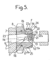
- Figure 5 is a schematic longitudinal section of another embodiment of the gear change device.
- a gear change device for a motor vehicle comprising, mounted in a casing 1, a primary shaft 2 connected to the engine by a clutch (not shown) and carrying a first pinion 3 integral in rotation with this shaft.
- the device also comprises a secondary shaft 4 linked in rotation to the driving wheels of the vehicle and carrying a second pinion 5 integral in rotation with this shaft.
- An axis 6 is integral with the casing 1; on this axis is mounted a sleeve 7 and on this sleeve a sliding pinion 8, in particular reverse gear.
- This pinion is adapted to be moved between a neutral position, shown in FIG. 1, where said pinion 8 does not mesh with the second pinion 5, and an active position represented in FIG. 2, where the pinion 8, while being in engagement with the first pinion 3, meshes with the second pinion 5.
- the sliding movements of the sliding pinion 8 are controlled by a drive member such as a fork (not shown) capable of cooperating with a groove 8a provided at the periphery of a cylindrical extension 8b of the pinion 8.
- a drive member such as a fork (not shown) capable of cooperating with a groove 8a provided at the periphery of a cylindrical extension 8b of the pinion 8.
- This sliding pinion 8 remains in permanent engagement with the first pinion 3; in the neutral position of FIG. 1, the pinion 8 therefore meshes with this pinion 3.
- Braking means F of the sliding pinion 8 relative to the fixed axis 6 are provided and comprise, in addition to the sleeve 7 slidably mounted on the axis 6, a finger 9 secured to the axis 6 suitable for cooperating with the sleeve 7 to limit the possible rotational movement of this sleeve relative to the axis 6.
- the finger 9 crosses completely, along a diameter, the axis 6 and projects at its two ends, on the external surface of the axis.
- the ends of the finger 9 are suitable for cooperating with two diametrically opposite grooves 10, 11 provided on the inner surface of the sleeve 7.
- the peripheral extent g (fig. 4) of the grooves 10, 11 is greater than the diameter of the finger 9 in the axial part 10a, 11a of these grooves located on the side of the end of the sliding pinion 8 provided with braking means F.
- the finger 9 is located at the axial level of this part 10a, 11a when the sliding pinion 8 is in the neutral position. It is understood that the sleeve 7 and the sliding pinion 8 can perform a limited rotational movement until the finger 9 abuts against the edges of the parts 10a, 11a, of the grooves. The latter extend, on the side opposite to the braking means F by a part such as 11 b (fig. 1) whose diameter is equal to that of finger 9.
- the parts 10a, 11a, of the grooves are connected to the parts such as 11b, by ramps such as 11c.
- Spacing means E are provided to separate the frustoconical surface 13 of the sleeve 7 from that 14 of the sliding pinion 8 when the latter is in the neutral or active position; the braking means intervene at least during a transient phase corresponding to the transition from the neutral position to the active position.
- the sliding pinion 8 is in permanent engagement with the first pinion 3, and the spacing means E are adapted to separate the two frustoconical surfaces 13 and 14 as well when the pinion 8 is in its neutral position than in its active position.
- Drive means 15 for the sleeve 7, by the pinion 8 are provided with an axial clearance j (fig. 2). These drive means comprise an elastic ring 16, split, engaged in a groove 17 provided at the end of the frustoconical inner surface 14 of the pinion 8.
- the drive of the sleeve 7 by the pinion 8, from the left to the right of FIG. 1, is ensured by the coming into contact of the surfaces 13 and 14, the surface 14 pushing the surface 13 and the sleeve 7 to the right; the axial clearance j between the end face of the sleeve 7 and the ring 16 is then maximum.
- the return of the sleeve 7 to the left of FIG. 1 is obtained when the pinion 8 is brought back from its active position to its neutral position, by cooperation of the ring 16 with the end face of the sleeve 7.
- the play j is then zero, while the spacing between the frustoconical surfaces 13 and 14 is maximum,
- the spacing means E comprise a device P for positioning the sleeve 7 on the axis 6, at two positions separated by a distance D greater than the distance d traveled by the sliding pinion 8 between its neutral position and its active position.
- the positioning device P comprises a pin 18 oriented radially, disposed in a radial housing 19 provided in the axis 6.
- the pin 18 is hollow and is closed, towards the outside, by a rounded end 20 adapted to cooperate with the surface inside of sleeve 7.
- the inner surface of the sleeve 7 has two notches 22, 23, of suitable concave shape intended to cooperate with the rounded end of the pin 18 so as to stop the sleeve 7, relative to the axis 6, in the one of the two positions separated by the distance D.
- the notches 22, 23 have a cross section greater than that of the pinion 18, so as to allow the limited rotational movement of the sleeve 7 relative to the axis 6.
- the notches 22, 23 are separated, in the axial direction, by a shoulder 24 from the inner surface of the sleeve 7, projecting radially inward.
- the notches 22, 23 are connected to the shoulder 24 by arming ramps 22a, 23a.
- the sleeve 7 is stopped axially, by the pin 18 which cooperates with the notch 22. Therefore, the start of the stroke of the pinion 8 towards its active position causes a relative sliding of the pinion 8 relative to the sleeve 7 and a reconciliation frustoconical surfaces 13 and 14.
- the sliding pinion 8 which is stopped in its translational movement by the sleeve 7 (which on the one hand, cooperates with the pin 18 and on the other hand, by the ramps such as 11 c, with the finger 9), is located then braked in rotation and, with it, the pinion 3 and the primary shaft 2.
- the sliding pinion 8 can continue its translational movement by driving the sleeve 7; the pin 18 is erased, by the ramp 22a and the shoulder 24, in its housing 19, while the finger 9 engages in the parts such as 11b of the grooves 10, 11.
- the sliding pinion When disengaging reverse gear, the sliding pinion is brought to the left of the figures, in neutral position, by the fork.
- the sleeve 7 is returned to the corresponding position thanks to the cooperation of the ring 16 and the end of this sleeve.
- the pin 18 is erased in its housing 19, by the ramp 23a.
- the shoulder 24 When the shoulder 24 has crossed the pin 18, the latter is housed in the notch 22 to stop the sleeve 7 in the position corresponding to the neutral position of the pinion 8.
- the assembly is arranged so that in this neutral position , the surfaces 13 and 14 are not in contact.
- the tapered surface 114 is formed on the outer surface of the end of the extension 8b of the pinion 8, while the tapered surface 113 is formed on the inner surface of a tapered ring 25 attached to the end of the sleeve 7 and stopped axially by a shoulder 26 of this sleeve.
- connection in rotation of the ring 25 and the sleeve 7 is ensured by a system of teeth and complementary grooves provided at the periphery of the sleeve and in the opening of the ring surrounding the sleeve.
- the sleeve 7 is made of a material with a low coefficient of friction, in particular in predominantly bronze sintered, which makes it possible to remove the ring 12, with a low coefficient of friction, provided in FIGS. 1 and 2.
- the pinion 8 is therefore mounted directly around the sleeve 7.
- the elastic ring 16 of FIGS. 1 and 2 is replaced by a rod 116 anchored in a groove provided at the periphery of the sleeve 7 and disposed in an annular groove 27 provided in the inner bore of the sliding pinion 8; the width of this groove 27 is greater than the diameter of the rod 116 so as to allow additional movements of the sleeve 7, relative to the pinion 8, ensuring the spacing of the frustoconical surfaces 113 and 114.
- the frustoconical surfaces of the braking means F rub against one another only during a short-term transient phase, so that the wear of these surfaces is reduced and l
- the efficiency of the braking means F is maintained while the operating time of the gear change device increases.
- the mounting of the pinion 8 around the sleeve 7 also contributes to reducing the size of the device.
Landscapes
- Engineering & Computer Science (AREA)
- General Engineering & Computer Science (AREA)
- Mechanical Engineering (AREA)
- Mechanical Operated Clutches (AREA)
- Gears, Cams (AREA)
Claims (7)
Applications Claiming Priority (2)
| Application Number | Priority Date | Filing Date | Title |
|---|---|---|---|
| FR7917665A FR2461156A1 (fr) | 1979-07-06 | 1979-07-06 | Perfectionnements aux dispositifs de changement de vitesses, notamment pour l'engagement de la marche arriere |
| FR7917665 | 1979-07-06 |
Publications (2)
| Publication Number | Publication Date |
|---|---|
| EP0022411A1 EP0022411A1 (de) | 1981-01-14 |
| EP0022411B1 true EP0022411B1 (de) | 1983-05-11 |
Family
ID=9227630
Family Applications (1)
| Application Number | Title | Priority Date | Filing Date |
|---|---|---|---|
| EP19800401016 Expired EP0022411B1 (de) | 1979-07-06 | 1980-07-03 | Verbesserungen in Schaltgetrieben, insbesondere zum Einlegen des Rückwärtsganges |
Country Status (3)
| Country | Link |
|---|---|
| EP (1) | EP0022411B1 (de) |
| DE (1) | DE3063114D1 (de) |
| FR (1) | FR2461156A1 (de) |
Cited By (1)
| Publication number | Priority date | Publication date | Assignee | Title |
|---|---|---|---|---|
| DE4106946A1 (de) * | 1991-03-05 | 1992-09-10 | Opel Adam Ag | Bremsvorrichtung fuer ein rueckwaertsgangrad |
Families Citing this family (13)
| Publication number | Priority date | Publication date | Assignee | Title |
|---|---|---|---|---|
| US4463622A (en) * | 1980-01-11 | 1984-08-07 | Deere & Company | Transmission and reverse gear synchronizing therefor |
| JPS57137747A (en) * | 1981-02-17 | 1982-08-25 | Toyota Motor Corp | Synchronizing device for speed changing gear |
| JPS60129428A (ja) * | 1983-12-16 | 1985-07-10 | Nissan Motor Co Ltd | 変速装置 |
| FR2604233B1 (fr) * | 1986-09-19 | 1991-02-08 | Renault | Dispositif de frein pour marche arriere de boite de vitesses. |
| IT1211201B (it) * | 1987-07-13 | 1989-10-12 | Fiat Auto Spa | Cambio di velocita ad ingranaggi per autoveicoli con dispositivo di innesto sincronizzato della retromarcia |
| DE3804142A1 (de) * | 1988-02-11 | 1989-08-24 | Vdo Schindling | Positionssensor |
| IT1250889B (it) * | 1991-12-23 | 1995-04-21 | Fiat Auto Spa | Cambio di velocita' ad ingranaggi sempre in presa per autoveicoli. |
| JP2766144B2 (ja) * | 1992-10-26 | 1998-06-18 | 株式会社クボタ | 作業機のptoクラッチ |
| KR100398241B1 (ko) * | 2001-05-18 | 2003-09-19 | 현대자동차주식회사 | 수동변속기의 후진 변속기구 |
| EP2682643A4 (de) * | 2011-03-04 | 2014-08-27 | Toyota Motor Co Ltd | Umkehrsynchronisierungsvorrichtung manuelles getriebe |
| DE102015222965A1 (de) * | 2015-11-20 | 2017-05-24 | Zf Friedrichshafen Ag | Antriebseinheit und Radantrieb mit Antriebseinheit |
| EP3208494B1 (de) * | 2016-02-22 | 2020-12-30 | GearMotive Oy | Getriebe |
| DE102016124920A1 (de) * | 2016-12-20 | 2018-06-21 | Claas Industrietechnik Gmbh | Schieberad für eine Schaltgetriebeanordnung |
Family Cites Families (2)
| Publication number | Priority date | Publication date | Assignee | Title |
|---|---|---|---|---|
| DE2018399C3 (de) * | 1970-04-17 | 1975-01-23 | Daimler-Benz Ag, 7000 Stuttgart | Einrichtung zum Einspuren eines Rückwärtsgang-Zahnrades bei einem insbesondere für Kraftfahrzeuge bestimmten Wechselgetriebe |
| DE2751699C3 (de) * | 1977-11-19 | 1981-03-12 | Volkswagenwerk Ag, 3180 Wolfsburg | Einrichtung zur geräuschlosen Schaltung eines Rückwärtsganges von Geschwindigkeitswechselgetrieben, insbesondere von Kraftfahrzeugen |
-
1979
- 1979-07-06 FR FR7917665A patent/FR2461156A1/fr active Granted
-
1980
- 1980-07-03 DE DE8080401016T patent/DE3063114D1/de not_active Expired
- 1980-07-03 EP EP19800401016 patent/EP0022411B1/de not_active Expired
Cited By (1)
| Publication number | Priority date | Publication date | Assignee | Title |
|---|---|---|---|---|
| DE4106946A1 (de) * | 1991-03-05 | 1992-09-10 | Opel Adam Ag | Bremsvorrichtung fuer ein rueckwaertsgangrad |
Also Published As
| Publication number | Publication date |
|---|---|
| FR2461156A1 (fr) | 1981-01-30 |
| FR2461156B1 (de) | 1982-11-19 |
| EP0022411A1 (de) | 1981-01-14 |
| DE3063114D1 (en) | 1983-06-16 |
Similar Documents
| Publication | Publication Date | Title |
|---|---|---|
| EP0022411B1 (de) | Verbesserungen in Schaltgetrieben, insbesondere zum Einlegen des Rückwärtsganges | |
| FR2739159A1 (fr) | Moyens a rampes pour dispositif de rattrapage de jeu destine a equiper un embrayage a friction, notamment pour vehicule automobile | |
| FR2875872A1 (fr) | Entrainement | |
| FR2619880A1 (fr) | Butee de debrayage, notamment pour vehicules automobiles | |
| EP0081025B1 (de) | Rotationsservomechanismus, insbesondere für eine Fahrzeuglenkung | |
| EP0845615A1 (de) | Kupplungsausrüstvorrichtung | |
| EP3959449B1 (de) | Getriebekasten und motor mit einem solchen getriebekasten | |
| FR2537519A1 (fr) | Systeme d'entrainement pour un mecanisme de rotation, de basculement et de deplacement d'un vehicule, notamment d'un excavateur, comportant un dispositif de freinage | |
| EP0685374A1 (de) | Getriebemotor, insbesondere für eine Fahrzeugscheibenwischeranlage | |
| FR2803640A1 (fr) | Ensemble synchroniseur pour une transmission d'un vehicule automobile | |
| EP2168867B1 (de) | Teleskopischer Stellantrieb mit Haupt- und Hilfstriebstange | |
| FR2813359A1 (fr) | Dispositif de maintien d'un billage dans un moyeu d'un ensemble synchroniseur pour vehicule automobile | |
| FR2851022A1 (fr) | Dispositif de synchronisation pour boite de vitesses mecanique | |
| FR2536482A1 (fr) | Butee d'embrayage a amortissement de bruit et de vibrations | |
| EP0333539B1 (de) | Lösbarer Linearschrittmotor mit einem rückzentrierten Läufer | |
| FR2750467A1 (fr) | Embrayage a friction a dispositif de rattrapage de jeu pour vehicule automobile | |
| FR2656054A1 (fr) | Synchroniseur de boite de vitesses. | |
| FR2539832A1 (fr) | Butee de debrayage de type tire en deux parties, notamment pour vehicule automobile | |
| EP1201952A1 (de) | Synchronisierung mit verringerter, störender Reibung | |
| FR2853377A1 (fr) | Synchroniseur de boite de vitesses notamment pour vehicules automobiles | |
| FR2783294A1 (fr) | Synchroniseur simple pour boite de vitesses notamment de vehicule automobile | |
| FR2745051A1 (fr) | Montage de butee de debrayage, notamment pour vehicule automobile | |
| FR2686669A1 (fr) | Dispositif de commande d'une boite de vitesses. | |
| EP1412655B1 (de) | Scheibenbremse für kratfahrzeuge mit nachstellvorrichtung des belagverschleisses | |
| FR2698141A1 (fr) | Dispositif de débrayage hydraulique pour embrayage à friction tiré. |
Legal Events
| Date | Code | Title | Description |
|---|---|---|---|
| PUAI | Public reference made under article 153(3) epc to a published international application that has entered the european phase |
Free format text: ORIGINAL CODE: 0009012 |
|
| AK | Designated contracting states |
Designated state(s): DE GB IT |
|
| 17P | Request for examination filed |
Effective date: 19810213 |
|
| ITF | It: translation for a ep patent filed |
Owner name: UFFICIO TECNICO ING. A. MANNUCCI |
|
| GRAA | (expected) grant |
Free format text: ORIGINAL CODE: 0009210 |
|
| AK | Designated contracting states |
Designated state(s): DE GB IT |
|
| REF | Corresponds to: |
Ref document number: 3063114 Country of ref document: DE Date of ref document: 19830616 |
|
| PGFP | Annual fee paid to national office [announced via postgrant information from national office to epo] |
Ref country code: DE Payment date: 19830802 Year of fee payment: 4 |
|
| PLBE | No opposition filed within time limit |
Free format text: ORIGINAL CODE: 0009261 |
|
| STAA | Information on the status of an ep patent application or granted ep patent |
Free format text: STATUS: NO OPPOSITION FILED WITHIN TIME LIMIT |
|
| 26N | No opposition filed | ||
| GBPC | Gb: european patent ceased through non-payment of renewal fee | ||
| PG25 | Lapsed in a contracting state [announced via postgrant information from national office to epo] |
Ref country code: DE Effective date: 19850402 |
|
| PG25 | Lapsed in a contracting state [announced via postgrant information from national office to epo] |
Ref country code: GB Effective date: 19881118 |