EP0022411B1 - Improvements in change-speed devices, particularly for engaging the reverse gear - Google Patents
Improvements in change-speed devices, particularly for engaging the reverse gear Download PDFInfo
- Publication number
- EP0022411B1 EP0022411B1 EP19800401016 EP80401016A EP0022411B1 EP 0022411 B1 EP0022411 B1 EP 0022411B1 EP 19800401016 EP19800401016 EP 19800401016 EP 80401016 A EP80401016 A EP 80401016A EP 0022411 B1 EP0022411 B1 EP 0022411B1
- Authority
- EP
- European Patent Office
- Prior art keywords
- sleeve
- gearwheel
- sliding
- frusto
- pinion
- Prior art date
- Legal status (The legal status is an assumption and is not a legal conclusion. Google has not performed a legal analysis and makes no representation as to the accuracy of the status listed.)
- Expired
Links
- 230000007935 neutral effect Effects 0.000 claims description 26
- 230000001052 transient effect Effects 0.000 claims description 4
- 229910000906 Bronze Inorganic materials 0.000 claims description 3
- 239000010974 bronze Substances 0.000 claims description 3
- KUNSUQLRTQLHQQ-UHFFFAOYSA-N copper tin Chemical compound [Cu].[Sn] KUNSUQLRTQLHQQ-UHFFFAOYSA-N 0.000 claims description 3
- 230000008859 change Effects 0.000 description 9
- 230000000295 complement effect Effects 0.000 description 3
- 239000000463 material Substances 0.000 description 3
- 238000000034 method Methods 0.000 description 2
- 230000008569 process Effects 0.000 description 2
- 230000009467 reduction Effects 0.000 description 2
- 230000007704 transition Effects 0.000 description 2
- 230000009471 action Effects 0.000 description 1
- 238000006073 displacement reaction Methods 0.000 description 1
- 230000000694 effects Effects 0.000 description 1
- 238000012423 maintenance Methods 0.000 description 1
- 230000000149 penetrating effect Effects 0.000 description 1
- 230000002093 peripheral effect Effects 0.000 description 1
- 239000004033 plastic Substances 0.000 description 1
- -1 polytetrafluoroethylene Polymers 0.000 description 1
- 229920001343 polytetrafluoroethylene Polymers 0.000 description 1
- 239000004810 polytetrafluoroethylene Substances 0.000 description 1
Images

Classifications
-
- F—MECHANICAL ENGINEERING; LIGHTING; HEATING; WEAPONS; BLASTING
- F16—ENGINEERING ELEMENTS AND UNITS; GENERAL MEASURES FOR PRODUCING AND MAINTAINING EFFECTIVE FUNCTIONING OF MACHINES OR INSTALLATIONS; THERMAL INSULATION IN GENERAL
- F16D—COUPLINGS FOR TRANSMITTING ROTATION; CLUTCHES; BRAKES
- F16D23/00—Details of mechanically-actuated clutches not specific for one distinct type
- F16D23/02—Arrangements for synchronisation, also for power-operated clutches
- F16D23/025—Synchro rings
-
- F—MECHANICAL ENGINEERING; LIGHTING; HEATING; WEAPONS; BLASTING
- F16—ENGINEERING ELEMENTS AND UNITS; GENERAL MEASURES FOR PRODUCING AND MAINTAINING EFFECTIVE FUNCTIONING OF MACHINES OR INSTALLATIONS; THERMAL INSULATION IN GENERAL
- F16H—GEARING
- F16H3/00—Toothed gearings for conveying rotary motion with variable gear ratio or for reversing rotary motion
- F16H3/02—Toothed gearings for conveying rotary motion with variable gear ratio or for reversing rotary motion without gears having orbital motion
- F16H3/20—Toothed gearings for conveying rotary motion with variable gear ratio or for reversing rotary motion without gears having orbital motion exclusively or essentially using gears that can be moved out of gear
- F16H3/38—Toothed gearings for conveying rotary motion with variable gear ratio or for reversing rotary motion without gears having orbital motion exclusively or essentially using gears that can be moved out of gear with synchro-meshing
- F16H3/385—Toothed gearings for conveying rotary motion with variable gear ratio or for reversing rotary motion without gears having orbital motion exclusively or essentially using gears that can be moved out of gear with synchro-meshing with braking means
-
- F—MECHANICAL ENGINEERING; LIGHTING; HEATING; WEAPONS; BLASTING
- F16—ENGINEERING ELEMENTS AND UNITS; GENERAL MEASURES FOR PRODUCING AND MAINTAINING EFFECTIVE FUNCTIONING OF MACHINES OR INSTALLATIONS; THERMAL INSULATION IN GENERAL
- F16H—GEARING
- F16H63/00—Control outputs from the control unit to change-speed- or reversing-gearings for conveying rotary motion or to other devices than the final output mechanism
- F16H63/02—Final output mechanisms therefor; Actuating means for the final output mechanisms
- F16H63/30—Constructional features of the final output mechanisms
- F16H63/302—Final output mechanisms for reversing
Definitions
- the invention relates more particularly, because it is in this case that its application seems to be of most interest, but not exclusively, gear change devices for motor vehicles.
- the object of the invention is, above all, to make gear-shifting devices of the kind in question such that they respond better than hitherto to the various requirements of practice and in particular such that they no longer have or are lesser degree of the disadvantages mentioned above.
- a speed change device of the kind defined above is characterized in that spacing means are provided to separate the frustoconical surface of the sleeve from that of the sliding pinion when the latter is in a neutral position or active.
- the sliding pinion is mounted on the sleeve; means for driving the sleeve through the pinion are provided with axial play, and the spacing means comprise a device for positioning the sleeve on said axis at two separate positions, in particular, by a distance greater than that traversed by the pinion player between its neutral position and its active position.
- the positioning device preferably comprises a pin, oriented radially, disposed in a housing provided in the aforesaid axis, and pushed elastically towards the outside, the outer end, rounded, of this pin being able to cooperate with two recesses provided on the inner surface of the sleeve and axially separated from each other by a shoulder capable of erasing the pin in its housing, the cooperation of the pin with a recess determining an axial position for the sleeve, the distance between the two positions axial thus determined being greater than the distance traveled by the sliding pinion.
- the sliding pinion can be mounted on the sleeve by means of a ring with a low coefficient of friction.
- the frustoconical surface of the sleeve is then provided on the outside, at one end of this sleeve, while the frustoconical surface of the sliding pinion is provided on an interior surface of this pinion, the means for driving the pinion by the sleeve comprising a elastic ring anchored in this inner surface of the pinion, adapted to cooperate with the end of the sleeve.
- the sliding pinion can be mounted directly on the sleeve, in particular when this sleeve is made of an appropriate material, for example predominantly bronze sintered; the frustoconical surface of the sleeve is then provided inside a frustoconical ring attached to one end of the sleeve, while the frustoconical surface of the sliding pinion is provided on an external surface of this pinion; the drive means of the pinion by the sleeve may comprise an elastic ring anchored around the sleeve and trapped in a groove of the pinion, with an axial clearance.
- Figure 1 of these drawings is a schematic longitudinal section of a gear change device according to the invention, with the sliding pinion in neutral position.
- Figure 2 is a simplified section of the device of Figure 1, with the sliding pinion in the active position.
- Figure 3 is a section along III-III of the axis and the sleeve.
- Figure 4 is a section along IV-IV of the axis and the sleeve.
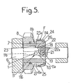
- Figure 5 is a schematic longitudinal section of another embodiment of the gear change device.
- a gear change device for a motor vehicle comprising, mounted in a casing 1, a primary shaft 2 connected to the engine by a clutch (not shown) and carrying a first pinion 3 integral in rotation with this shaft.
- the device also comprises a secondary shaft 4 linked in rotation to the driving wheels of the vehicle and carrying a second pinion 5 integral in rotation with this shaft.
- An axis 6 is integral with the casing 1; on this axis is mounted a sleeve 7 and on this sleeve a sliding pinion 8, in particular reverse gear.
- This pinion is adapted to be moved between a neutral position, shown in FIG. 1, where said pinion 8 does not mesh with the second pinion 5, and an active position represented in FIG. 2, where the pinion 8, while being in engagement with the first pinion 3, meshes with the second pinion 5.
- the sliding movements of the sliding pinion 8 are controlled by a drive member such as a fork (not shown) capable of cooperating with a groove 8a provided at the periphery of a cylindrical extension 8b of the pinion 8.
- a drive member such as a fork (not shown) capable of cooperating with a groove 8a provided at the periphery of a cylindrical extension 8b of the pinion 8.
- This sliding pinion 8 remains in permanent engagement with the first pinion 3; in the neutral position of FIG. 1, the pinion 8 therefore meshes with this pinion 3.
- Braking means F of the sliding pinion 8 relative to the fixed axis 6 are provided and comprise, in addition to the sleeve 7 slidably mounted on the axis 6, a finger 9 secured to the axis 6 suitable for cooperating with the sleeve 7 to limit the possible rotational movement of this sleeve relative to the axis 6.
- the finger 9 crosses completely, along a diameter, the axis 6 and projects at its two ends, on the external surface of the axis.
- the ends of the finger 9 are suitable for cooperating with two diametrically opposite grooves 10, 11 provided on the inner surface of the sleeve 7.
- the peripheral extent g (fig. 4) of the grooves 10, 11 is greater than the diameter of the finger 9 in the axial part 10a, 11a of these grooves located on the side of the end of the sliding pinion 8 provided with braking means F.
- the finger 9 is located at the axial level of this part 10a, 11a when the sliding pinion 8 is in the neutral position. It is understood that the sleeve 7 and the sliding pinion 8 can perform a limited rotational movement until the finger 9 abuts against the edges of the parts 10a, 11a, of the grooves. The latter extend, on the side opposite to the braking means F by a part such as 11 b (fig. 1) whose diameter is equal to that of finger 9.
- the parts 10a, 11a, of the grooves are connected to the parts such as 11b, by ramps such as 11c.
- Spacing means E are provided to separate the frustoconical surface 13 of the sleeve 7 from that 14 of the sliding pinion 8 when the latter is in the neutral or active position; the braking means intervene at least during a transient phase corresponding to the transition from the neutral position to the active position.
- the sliding pinion 8 is in permanent engagement with the first pinion 3, and the spacing means E are adapted to separate the two frustoconical surfaces 13 and 14 as well when the pinion 8 is in its neutral position than in its active position.
- Drive means 15 for the sleeve 7, by the pinion 8 are provided with an axial clearance j (fig. 2). These drive means comprise an elastic ring 16, split, engaged in a groove 17 provided at the end of the frustoconical inner surface 14 of the pinion 8.
- the drive of the sleeve 7 by the pinion 8, from the left to the right of FIG. 1, is ensured by the coming into contact of the surfaces 13 and 14, the surface 14 pushing the surface 13 and the sleeve 7 to the right; the axial clearance j between the end face of the sleeve 7 and the ring 16 is then maximum.
- the return of the sleeve 7 to the left of FIG. 1 is obtained when the pinion 8 is brought back from its active position to its neutral position, by cooperation of the ring 16 with the end face of the sleeve 7.
- the play j is then zero, while the spacing between the frustoconical surfaces 13 and 14 is maximum,
- the spacing means E comprise a device P for positioning the sleeve 7 on the axis 6, at two positions separated by a distance D greater than the distance d traveled by the sliding pinion 8 between its neutral position and its active position.
- the positioning device P comprises a pin 18 oriented radially, disposed in a radial housing 19 provided in the axis 6.
- the pin 18 is hollow and is closed, towards the outside, by a rounded end 20 adapted to cooperate with the surface inside of sleeve 7.
- the inner surface of the sleeve 7 has two notches 22, 23, of suitable concave shape intended to cooperate with the rounded end of the pin 18 so as to stop the sleeve 7, relative to the axis 6, in the one of the two positions separated by the distance D.
- the notches 22, 23 have a cross section greater than that of the pinion 18, so as to allow the limited rotational movement of the sleeve 7 relative to the axis 6.
- the notches 22, 23 are separated, in the axial direction, by a shoulder 24 from the inner surface of the sleeve 7, projecting radially inward.
- the notches 22, 23 are connected to the shoulder 24 by arming ramps 22a, 23a.
- the sleeve 7 is stopped axially, by the pin 18 which cooperates with the notch 22. Therefore, the start of the stroke of the pinion 8 towards its active position causes a relative sliding of the pinion 8 relative to the sleeve 7 and a reconciliation frustoconical surfaces 13 and 14.
- the sliding pinion 8 which is stopped in its translational movement by the sleeve 7 (which on the one hand, cooperates with the pin 18 and on the other hand, by the ramps such as 11 c, with the finger 9), is located then braked in rotation and, with it, the pinion 3 and the primary shaft 2.
- the sliding pinion 8 can continue its translational movement by driving the sleeve 7; the pin 18 is erased, by the ramp 22a and the shoulder 24, in its housing 19, while the finger 9 engages in the parts such as 11b of the grooves 10, 11.
- the sliding pinion When disengaging reverse gear, the sliding pinion is brought to the left of the figures, in neutral position, by the fork.
- the sleeve 7 is returned to the corresponding position thanks to the cooperation of the ring 16 and the end of this sleeve.
- the pin 18 is erased in its housing 19, by the ramp 23a.
- the shoulder 24 When the shoulder 24 has crossed the pin 18, the latter is housed in the notch 22 to stop the sleeve 7 in the position corresponding to the neutral position of the pinion 8.
- the assembly is arranged so that in this neutral position , the surfaces 13 and 14 are not in contact.
- the tapered surface 114 is formed on the outer surface of the end of the extension 8b of the pinion 8, while the tapered surface 113 is formed on the inner surface of a tapered ring 25 attached to the end of the sleeve 7 and stopped axially by a shoulder 26 of this sleeve.
- connection in rotation of the ring 25 and the sleeve 7 is ensured by a system of teeth and complementary grooves provided at the periphery of the sleeve and in the opening of the ring surrounding the sleeve.
- the sleeve 7 is made of a material with a low coefficient of friction, in particular in predominantly bronze sintered, which makes it possible to remove the ring 12, with a low coefficient of friction, provided in FIGS. 1 and 2.
- the pinion 8 is therefore mounted directly around the sleeve 7.
- the elastic ring 16 of FIGS. 1 and 2 is replaced by a rod 116 anchored in a groove provided at the periphery of the sleeve 7 and disposed in an annular groove 27 provided in the inner bore of the sliding pinion 8; the width of this groove 27 is greater than the diameter of the rod 116 so as to allow additional movements of the sleeve 7, relative to the pinion 8, ensuring the spacing of the frustoconical surfaces 113 and 114.
- the frustoconical surfaces of the braking means F rub against one another only during a short-term transient phase, so that the wear of these surfaces is reduced and l
- the efficiency of the braking means F is maintained while the operating time of the gear change device increases.
- the mounting of the pinion 8 around the sleeve 7 also contributes to reducing the size of the device.
Landscapes
- Engineering & Computer Science (AREA)
- General Engineering & Computer Science (AREA)
- Mechanical Engineering (AREA)
- Mechanical Operated Clutches (AREA)
- Gears, Cams (AREA)
Description
L'invention est relative à des perfectionnements apportés aux dispositifs de changement de vitesses, du genre de ceux qui comprennent, montés dans un carter :
- - un premier pignon solidaire d'un arbre primaire ;
- - un deuxième pignon solidaire d'un arbre secondaire ;
- - un pignon baladeur, notamment de marche arrière, monté coulissant sur un axe solidaire du carter et propre à être déplacé, par un organe d'entraînement, entre une position neutre et une position active où ledit pignon baladeur, en prise avec le premier pignon, engrène avec le second pignon, ce pignon baladeur étant en prise permanente avec le premier pignon ;
- - des moyens de freinage du pignon baladeur comportant un manchon monté coulissant sur ledit axe et susceptible d'être animé par rapport à cet axe d'un mouvement de rotation limité par un doigt solidaire de l'axe et coopérant avec une fente axiale du manchon, ledit manchon portant une surface tronconique coopérant avec une surface tronconique complémentaire formée sur le pignon baladeur, ces moyens de freinage intervenant au moins pendant une phase transitoire correspondant au passage de la position neutre à la position active.
- - a first pinion secured to a primary shaft;
- - a second pinion secured to a secondary shaft;
- - a sliding pinion, in particular of reverse gear, mounted sliding on an axis integral with the casing and suitable for being moved, by a drive member, between a neutral position and an active position where said sliding pinion, in engagement with the first pinion , meshes with the second pinion, this sliding pinion being in permanent engagement with the first pinion;
- - braking means of the sliding pinion comprising a sleeve mounted to slide on said axis and capable of being driven relative to this axis of a rotational movement limited by a finger integral with the axis and cooperating with an axial slot of the sleeve , said sleeve carrying a frustoconical surface cooperating with a complementary frustoconical surface formed on the sliding pinion, these braking means acting at least during a transient phase corresponding to the transition from the neutral position to the active position.
L'invention concerne plus particulièrement, parce que c'est dans ce cas que son application semble devoir présenter le plus d'intérêt, mais non exclusivement, les dispositifs de changement de vitesses pour véhicules automobiles.The invention relates more particularly, because it is in this case that its application seems to be of most interest, but not exclusively, gear change devices for motor vehicles.
Le document FR-A-2409419 montre un dispositif de ce genre dans lequel les moyens de freinage comprennent un anneau de freinage muni, d'une part, de dents propres à pénétrer dans des rainures de guidage prévues sur un prolongement du pignon baladeur, et, d'autre part, d'un cône de synchronisation propre à coopérer avec un cône interne d'un manchon immobile. Bien que ce cône de synchronisation ne soit appliqué positivement contre le cône du manchon immobile que pendant le processus de synchronisation, avec apparition d'un frottement important entre ces deux cônes, il n'en demeure pas moins que les surfaces des deux cônes restent au voisinage l'une de l'autre en dehors du processus de synchronisation et peuvent venir frotter l'une sur l'autre.The document FR-A-2409419 shows a device of this kind in which the braking means comprise a braking ring provided, on the one hand, with teeth suitable for penetrating into guide grooves provided on an extension of the sliding pinion, and , on the other hand, a synchronization cone adapted to cooperate with an internal cone of a stationary sleeve. Although this synchronization cone is only applied positively against the cone of the stationary sleeve during the synchronization process, with the appearance of significant friction between these two cones, the fact remains that the surfaces of the two cones remain at outside of the synchronization process and can rub against each other.
Il peut en résulter une usure relativement rapide de ces surfaces conduisant à une diminution de l'efficacité des moyens de freinage.This can result in relatively rapid wear of these surfaces leading to a reduction in the effectiveness of the braking means.
L'invention a pour but, surtout, de rendre les dispositifs de changement de vitesses du genre en question tels qu'ils répondent mieux que jusqu'à présent aux diverses exigences de la pratique et notamment tels qu'ils ne présentent plus ou à un degré moindre les inconvénients mentionnés ci-dessus.The object of the invention is, above all, to make gear-shifting devices of the kind in question such that they respond better than hitherto to the various requirements of practice and in particular such that they no longer have or are lesser degree of the disadvantages mentioned above.
Selon l'invention, un dispositif de changement de vitesse du genre défini précédemment est caractérisé par le fait que des moyens d'écartement sont prévus pour écarter la surface tronconique du manchon de celle du pignon baladeur lorsque ce dernier se trouve dans une position neutre ou active.According to the invention, a speed change device of the kind defined above is characterized in that spacing means are provided to separate the frustoconical surface of the sleeve from that of the sliding pinion when the latter is in a neutral position or active.
Avantageusement, le pignon baladeur est monté sur le manchon ; des moyens d'entraînement du manchon par le pignon sont prévus avec un jeu axial, et les moyens d'écartement comprennent un dispositif de positionnement du manchon sur ledit axe à deux positions séparées, notamment, par une distance supérieure à celle parcourue par le pignon baladeur entre sa position neutre et sa position active.Advantageously, the sliding pinion is mounted on the sleeve; means for driving the sleeve through the pinion are provided with axial play, and the spacing means comprise a device for positioning the sleeve on said axis at two separate positions, in particular, by a distance greater than that traversed by the pinion player between its neutral position and its active position.
Le dispositif de positionnement comprend, de préférence, un pion, orienté radialement, disposé dans un logement prévu dans le susdit axe, et poussé élastiquement vers l'extérieur, l'extrémité extérieure, arrondie, de ce pion étant propre à coopérer avec deux évidements prévus sur la surface intérieure du manchon et séparés axialement l'un de l'autre par un épaulement propre à effacer le pion dans son logement, la coopération du pion avec un évidement déterminant une position axiale pour le manchon, la distance entre les deux positions axiales ainsi déterminées étant supérieure à la distance parcourue par le pignon baladeur.The positioning device preferably comprises a pin, oriented radially, disposed in a housing provided in the aforesaid axis, and pushed elastically towards the outside, the outer end, rounded, of this pin being able to cooperate with two recesses provided on the inner surface of the sleeve and axially separated from each other by a shoulder capable of erasing the pin in its housing, the cooperation of the pin with a recess determining an axial position for the sleeve, the distance between the two positions axial thus determined being greater than the distance traveled by the sliding pinion.
Le pignon baladeur peut être monté sur le manchon par l'intermédiaire d'une bague à faible coefficient de frottement.The sliding pinion can be mounted on the sleeve by means of a ring with a low coefficient of friction.
La surface tronconique du manchon est alors prévue à l'extérieur, à une extrémité de ce manchon, tandis que la surface tronconique du pignon baladeur est prévue sur une surface intérieure de ce pignon, les moyens d'entraînement du pignon par le manchon comprenant une bague élastique ancrée dans cette surface intérieure du pignon, propre à coopérer avec l'extrémité du manchon.The frustoconical surface of the sleeve is then provided on the outside, at one end of this sleeve, while the frustoconical surface of the sliding pinion is provided on an interior surface of this pinion, the means for driving the pinion by the sleeve comprising a elastic ring anchored in this inner surface of the pinion, adapted to cooperate with the end of the sleeve.
Le pignon baladeur peut être monté directement sur le manchon, notamment lorsque ce manchon est réalisé en une matière appropriée, par exemple en fritté à prédominance bronze ; la surface tronconique du manchon est alors prévue à l'intérieur d'un anneau tronconique rapporté à une extrémité du manchon, tandis que la surface - tronconique du pignon baladeur est prévue sur une surface extérieure de ce pignon ; les moyens d'entraînement du pignon par le manchon peuvent comprendre un jonc élastique ancré autour du manchon et emprisonné dans une gorge du pignon, avec un jeu axial.The sliding pinion can be mounted directly on the sleeve, in particular when this sleeve is made of an appropriate material, for example predominantly bronze sintered; the frustoconical surface of the sleeve is then provided inside a frustoconical ring attached to one end of the sleeve, while the frustoconical surface of the sliding pinion is provided on an external surface of this pinion; the drive means of the pinion by the sleeve may comprise an elastic ring anchored around the sleeve and trapped in a groove of the pinion, with an axial clearance.
L'invention sera décrite en détail avec référence aux dessins ci-annexés.The invention will be described in detail with reference to the accompanying drawings.
La figure 1 de ces dessins est une coupe longitudinale schématique d'un dispositif de changement de vitesses conforme à l'invention, avec le pignon baladeur en position neutre.Figure 1 of these drawings is a schematic longitudinal section of a gear change device according to the invention, with the sliding pinion in neutral position.
La figure 2 est une coupe simplifiée du dispositif de la figure 1, avec le pignon baladeur en position active.Figure 2 is a simplified section of the device of Figure 1, with the sliding pinion in the active position.
La figure 3 est une coupe suivant III-III de l'axe et du manchon.Figure 3 is a section along III-III of the axis and the sleeve.
La figure 4 est une coupe suivant IV-IV de l'axe et du manchon.Figure 4 is a section along IV-IV of the axis and the sleeve.
La figure 5, enfin, est une coupe longitudinale, schématique d'un autre mode de réalisation du dispositif de changement de vitesses.Figure 5, finally, is a schematic longitudinal section of another embodiment of the gear change device.
En se reportant aux dessins, et plus particulièrement à la figure 1, on peut voir un dispositif de changement de vitesses, pour véhicule automobile, comprenant, montés dans un carter 1, un arbre primaire 2 relié au moteur par l'intermédiaire d'un embrayage (non montré) et portant un premier pignon 3 solidaire en rotation de cet arbre. Le dispositif comprend également un arbre secondaire 4 lié en rotation aux roues motrices du véhicule et portant un deuxième pignon 5 solidaire en rotation de cet arbre.Referring to the drawings, and more particularly to FIG. 1, one can see a gear change device for a motor vehicle, comprising, mounted in a casing 1, a primary shaft 2 connected to the engine by a clutch (not shown) and carrying a
Un axe 6 est solidaire du carter 1 ; sur cet axe est monté un manchon 7 et sur ce manchon un pignon baladeur 8, en particulier de marche arrière. Ce pignon est propre à être déplacé entre une position neutre, représentée sur la figure 1, où ledit pignon 8 n'engrène pas avec le second pignon 5, et une position active représentée sur la figure 2, où le pignon 8, tout en étant en prise avec le premier pignon 3, engrène avec le second pignon 5.An
Les déplacements en coulissement du pignon baladeur 8 sont commandés par un organe d'entraînement tel qu'une fourchette (non représentée) propre à coopérer avec une gorge 8a prévue à la périphérie d'un prolongement cylindrique 8b du pignon 8.The sliding movements of the
Ce pignon baladeur 8 reste en prise permanente avec le premier pignon 3 ; dans la position neutre de la figure 1, le pignon 8 engrène donc avec ce pignon 3.This sliding
Des moyens de freinage F du pignon baladeur 8 par rapport à l'axe fixe 6 sont prévus et comprennent, outre le manchon 7 monté coulissant sur l'axe 6, un doigt 9 solidaire de l'axe 6 propre à coopérer avec le manchon 7 pour limiter le mouvement de rotation possible de ce manchon par rapport à l'axe 6.Braking means F of the
Comme bien visible sur la figure 4, le doigt 9 traverse complètement, suivant un diamètre, l'axe 6 et fait saillie à ses deux extrémités, sur la surface extérieure de l'axe. Les extrémités du doigt 9 sont propres à coopérer avec deux rainures 10, 11 diamétralement opposées prévues sur la surface intérieure du manchon 7. L'étendue périphérique g (fig. 4) des rainures 10, 11, est supérieure au diamètre du doigt 9 dans la partie axiale 10a, 11a de ces rainures située du côté de l'extrémité du pignon baladeur 8 munie des moyens de freinage F.As clearly visible in FIG. 4, the
Le doigt 9 se trouve au niveau axial de cette partie 10a, 11a lorsque le pignon baladeur 8 est en position neutre. On comprend que le manchon 7 et le pignon baladeur 8 peuvent effectuer un mouvement de rotation limité jusqu'à ce que le doigt 9 vienne en butée contre les bords des parties 10a, 11a, des rainures. Ces dernières se prolongent, du côté opposé aux moyens de freinage F par une partie telle que 11 b (fig. 1) dont le diamètre est égal à celui du doigt 9.The
Les parties 10a, 11a, des rainures sont reliées aux parties telles que 11 b, par des rampes telles que 11 c.The
Une bague 12 à faible coefficient de frottement, par exemple en matière plastique auto-lubrifiante telle que du polytétrafluoréthylène, est disposée entre le pignon baladeur et le manchon 7. Ce manchon porte à sa périphérie extérieure une surface tronconique 13 propre à coopérer avec une surface complémentaire 14 prévue sur la surface intérieure du prolongement 8b du pignon 8. Ces surfaces tronconiques 13 et 14 appartiennent aux moyens de freinage F ; la venue en contact de ces deux surfaces permet de freiner le pignon 8 par rapport au manchon 7.A
Des moyens d'écartement E sont prévus pour écarter la surface tronconique 13 du manchon 7 de celle 14 du pignon baladeur 8 lorsque ce dernier se trouve dans la position neutre ou active ; les moyens de freinage interviennent au moins pendant une phase transitoire correspondant au passage de la position neutre à la position active.Spacing means E are provided to separate the frustoconical surface 13 of the
Dans le mode de réalisation particulier, décrit avec référence aux dessins, le pignon baladeur 8 est en prise permanente avec le premier pignon 3, et les moyens d'écartement E sont propres à écarter les deux surfaces tronconiques 13 et 14 aussi bien lorsque le pignon 8 est dans sa position neutre que dans sa position active.In the particular embodiment, described with reference to the drawings, the
Des moyens d'entraînement 15 du manchon 7, par le pignon 8 sont prévus avec un jeu axial j (fig. 2). Ces moyens d'entraînement comprennent une bague élastique 16, fendue, engagée dans une gorge 17 prévue à l'extrémité de la surface intérieure tronconique 14 du pignon 8.Drive means 15 for the
L'entraînement du manchon 7 par le pignon 8, de la gauche vers la droite de la figure 1, est assuré par la venue en contact des surfaces 13 et 14, la surface 14 poussant la surface 13 et le manchon 7 vers la droite ; le jeu axial j entre la face extrême du manchon 7 et la bague 16 est alors maximal. Le retour du manchon 7 vers la gauche de la figure 1 est obtenu lorsque le pignon 8 est ramené de sa position active à sa position neutre, par coopération de la bague 16 avec la face extrême du manchon 7. Le jeu j est alors nul, tandis que l'écartement entre les surfaces tronconiques 13 et 14 est maximal,The drive of the
Les moyens d'écartement E comprennent un dispositif de positionnement P du manchon 7 sur l'axe 6, à deux positions séparées par une distance D supérieure à la distance d parcourue par le pignon baladeur 8 entre sa position neutre et sa position active.The spacing means E comprise a device P for positioning the
Le dispositif de positionnement P comprend un pion 18 orienté radialement, disposé dans un logement radial 19 prévu dans l'axe 6. Le pion 18 est creux et est fermé, vers l'extérieur, par une extrémité arrondie 20 propre à coopérer avec la surface intérieure du manchon 7.The positioning device P comprises a
Le pion 18 est poussé élastiquement vers l'extérieur par un ressort 21 logé à l'intérieur du pion et prenant appui contre l'extrémité fermée du logement 19.The
La surface intérieure du manchon 7 comporte deux encoches 22, 23, de forme concave appropriée destinées à coopérer avec l'extrémité arrondie du pion 18 de manière à assurer l'arrêt du manchon 7, par rapport à l'axe 6, dans l'une des deux positions séparées par la distance D.The inner surface of the
Lorsque le pion 18 coopère avec l'encoche 22, le pignon 8 est en position neutre et le manchon 7 occupe la position correspondante ; lorsque le pion 18 coopère avec l'encoche 23 (fig. 2) le pignon 8 est en position active et le manchon 7 occupe la position correspondante.When the
Comme visible sur la figure 3, les encoches 22, 23 ont une section transversale supérieure à celle du pignon 18, de manière à permettre le mouvement de rotation limité du manchon 7 par rapport à l'axe 6.As shown in FIG. 3, the
Les encoches 22, 23 sont séparées, dans le sens axial, par un épaulement 24 de la surface intérieure du manchon 7, faisant saillie radialement vers l'intérieur. Les encoches 22, 23 se raccordent à l'épaulement 24 par des rampes d'armement 22a, 23a.The
Le fonctionnement du dispositif des figures 1 à 4 est le suivant.The operation of the device in FIGS. 1 to 4 is as follows.
Lorsque le dispositif de changement de vitesses est au point mort, le pignon baladeur 8 se trouve dans sa position neutre représentée sur la figure 1, où il est en prise avec le pignon 3 solidaire de l'arbre primaire 2. Comme expliqué précédemment, bien que le moteur soit débrayé de l'arbre 2, le couple résiduel de l'embrayage provoque la rotation de cet arbre 2, le pignon 8 tourne librement sur la bague 12, par rapport au manchon 7. Le pignon 5, solidaire de l'arbre secondaire 4 lié en rotation aux roues, est arrêté.When the gear change device is in neutral, the
Lors du passage de la marche arrière, le pignon baladeur 8 est déplacé (par l'intermédiaire de la fourchette non montrée) vers sa position active, en direction du pignon 5.When shifting from reverse gear, the
Le manchon 7 est arrêté axialement, par le pion 18 qui coopère avec l'encoche 22. De ce fait, le début de la course du pignon 8 vers sa position active entraîne un coulissement relatif du pignon 8 par rapport au manchon 7 et un rapprochement des surfaces tronconiques 13 et 14.The
Lorsque ces deux surfaces tronconiques 13 et 14 entrent en contact, le manchon 7 est entraîné en rotation par le pignon 8 jusqu'à ce qu'un des bords des parties 10a, 11a des rainures 10, 11 vienne en contact avec le doigt 9 (fig. 4).When these two frustoconical surfaces 13 and 14 come into contact, the
Le pignon baladeur 8 qui est arrêté dans son mouvement de translation par le manchon 7 (lequel d'une part, coopère avec le pion 18 et d'autre part, par les rampes telles que 11 c, avec le doigt 9), se trouve alors freiné en rotation et, avec lui, le pignon 3 et l'arbre primaire 2.The sliding
Lorsque tout l'ensemble est arrêté en rotation, le pignon baladeur 8 peut poursuivre son mouvement de translation en entraînant le manchon 7 ; le pion 18 est effacé, par la rampe 22a et l'épaulement 24, dans son logement 19, tandis que le doigt 9 s'engage dans les parties telles que 11 b des rainures 10, 11.When the whole assembly is stopped in rotation, the sliding
Pendant la poursuite de ce mouvement de translation, le pignon 8 est arrêté en rotation par rapport à l'axe 6, grâce aux moyens de freinage F.During the continuation of this translational movement, the
Lorsque le pignon baladeur 8 arrive en prise avec le pignon 5, l'épaulement 24 a franchi le pion 18 qui, sous l'action du ressort 21, exerce une pression vers l'extérieur contre la rampe inclinée 23a ; sous l'effet de cette pression, le manchon 7 continue à se déplacer vers la droite, alors que le pignon 8 est arrêté en position active de marche arrière. Le déplacement du manchon 7 se poursuit jusqu'à ce que l'extrémité arrondie du pion 18 pénètre dans l'encoche 23. Les surfaces tronconiques 13 et 14 sont ainsi écartées l'une de l'autre, dans le sens axial, et leur contact est supprimé pendant la marche arrière.When the sliding
Lors du désengagement de la marche arrière, le pignon baladeur est ramené vers la gauche des figures, en position neutre, par la fourchette. Le manchon 7 est ramené dans la position correspondante grâce à la coopération de la bague 16 et de l'extrémité de ce manchon. Le pion 18 est effacé dans son logement 19, par la rampe 23a. Lorsque l'épaulement 24 a franchi le pion 18, ce dernier vient se loger dans l'encoche 22 pour arrêter le manchon 7 dans la position correspondant à la position neutre du pignon 8. L'ensemble est agencé de manière que dans cette position neutre, les surfaces 13 et 14 ne soient pas en contact.When disengaging reverse gear, the sliding pinion is brought to the left of the figures, in neutral position, by the fork. The
En se reportant à la figure 5, on peut voir une variante de réalisation du dispositif de changement de vitesses selon l'invention.Referring to Figure 5, we can see an alternative embodiment of the gear change device according to the invention.
Les éléments identiques à des éléments déjà décrits avec référence aux figures 1 à 4 sont désignés par les mêmes références numériques.Elements identical to elements already described with reference to Figures 1 to 4 are designated by the same reference numerals.
Les éléments modifiés par rapport à la réalisation des figures 1 à 4, éléments dont il va être question ci-après, sont désignés par les références numériques d'éléments des figures 1 à 4, ayant des fonctions semblables, augmentées du nombre 100.The elements modified with respect to the embodiment of FIGS. 1 to 4, elements which will be discussed below, are designated by the reference numbers of elements in FIGS. 1 to 4, having similar functions, increased by the number 100.
La surface tronconique 114 est réalisée sur la surface extérieure de l'extrémité du prolongement 8b du pignon 8, tandis que la surface tronconique 113 est réalisée sur la surface intérieure d'un anneau tronconique 25 rapporté sur l'extrémité du manchon 7 et arrêté axialement par un épaulement 26 de ce manchon.The tapered surface 114 is formed on the outer surface of the end of the
La liaison en rotation de l'anneau 25 et du manchon 7 est assurée par un système de dents et de cannelures complémentaires prévues à la périphérie du manchon et dans l'ouverture de l'anneau entourant le manchon.The connection in rotation of the
Le manchon 7 est réalisé en une matière à faible coefficient de frottement, notamment en fritté à prédominance bronze, ce qui permet de supprimer la bague 12, à faible coefficient de frottement, prévue sur les figures 1 et 2. Le pignon 8 est donc monté directement autour du manchon 7.The
La bague élastique 16 des figures 1 et 2 est remplacée par un jonc 116 ancré dans une rainure prévue à la périphérie du manchon 7 et disposé dans une gorge 27 annulaire prévue dans l'alésage intérieur du pignon baladeur 8 ; la largeur de cette gorge 27 est supérieure au diamètre du jonc 116 de manière à permettre les déplacements supplémentaires du manchon 7, par rapport au pignon 8, assurant l'écartement des surfaces tronconiques 113 et 114.The
Le fonctionnement est identique à celui du mode de réalisation des figures 1 à 4.The operation is identical to that of the embodiment of FIGS. 1 to 4.
Les surfaces tronconiques 113 et 114 ne viennent en contact que pendant la phase transitoire correspondant au passage du pignon baladeur 8 de la position neutre à la position active. Le freinage en rotation de ce pignon 8 est alors assuré.The frustoconical surfaces 113 and 114 come into contact only during the transitional phase corresponding to the passage of the sliding
Lors du désengagement de la marche arrière, l'entraînement du manchon 7 par le pignon 8 est assuré par le jonc 116 qui coopère avec la gorge 27.When the reverse gear is disengaged, the
Quel que soit le mode de réalisation adopté, les surfaces tronconiques des moyens de freinage F ne viennent frotter l'une contre l'autre que pendant une phase transitoire de courte durée, de telle sorte que l'usure de ces surfaces est réduite et l'efficacité des moyens de freinage F est conservée alors que le temps de fonctionnement du dispositif de changement de vitesses augmente.Whatever the embodiment adopted, the frustoconical surfaces of the braking means F rub against one another only during a short-term transient phase, so that the wear of these surfaces is reduced and l The efficiency of the braking means F is maintained while the operating time of the gear change device increases.
Le montage du pignon 8 en prise avec le pignon 3 en position neutre permet de réduire au minimum la course axiale nécessaire audit pignon 8 pour engrener avec le pignon 5. Il en résulte une réduction de l'encombrement axial du dispositif, sans inconvénient sur le maintien de sort efficacité dans le temps puisque les surfaces tronconiques 13, 14 sont écartées l'une de l'autre lorsque le pignon 8 est en position neutre.The mounting of the
Le montage du pignon 8 autour du manchon 7 contribue, également, à réduire l'encombrement du dispositif.The mounting of the
Claims (7)
Applications Claiming Priority (2)
| Application Number | Priority Date | Filing Date | Title |
|---|---|---|---|
| FR7917665A FR2461156A1 (en) | 1979-07-06 | 1979-07-06 | IMPROVEMENTS TO SHIFTING DEVICES, IN PARTICULAR FOR THE COMMITMENT OF THE REVERSE MARKET |
| FR7917665 | 1979-07-06 |
Publications (2)
| Publication Number | Publication Date |
|---|---|
| EP0022411A1 EP0022411A1 (en) | 1981-01-14 |
| EP0022411B1 true EP0022411B1 (en) | 1983-05-11 |
Family
ID=9227630
Family Applications (1)
| Application Number | Title | Priority Date | Filing Date |
|---|---|---|---|
| EP19800401016 Expired EP0022411B1 (en) | 1979-07-06 | 1980-07-03 | Improvements in change-speed devices, particularly for engaging the reverse gear |
Country Status (3)
| Country | Link |
|---|---|
| EP (1) | EP0022411B1 (en) |
| DE (1) | DE3063114D1 (en) |
| FR (1) | FR2461156A1 (en) |
Cited By (1)
| Publication number | Priority date | Publication date | Assignee | Title |
|---|---|---|---|---|
| DE4106946A1 (en) * | 1991-03-05 | 1992-09-10 | Opel Adam Ag | Brake device for reverse gear wheel - can be preassembled with gearwheel for easy insertion in gearbox |
Families Citing this family (13)
| Publication number | Priority date | Publication date | Assignee | Title |
|---|---|---|---|---|
| US4463622A (en) * | 1980-01-11 | 1984-08-07 | Deere & Company | Transmission and reverse gear synchronizing therefor |
| JPS57137747A (en) * | 1981-02-17 | 1982-08-25 | Toyota Motor Corp | Synchronizing device for speed changing gear |
| JPS60129428A (en) * | 1983-12-16 | 1985-07-10 | Nissan Motor Co Ltd | Transmission gear |
| FR2604233B1 (en) * | 1986-09-19 | 1991-02-08 | Renault | BRAKE DEVICE FOR REVERSE GEARBOX. |
| IT1211201B (en) * | 1987-07-13 | 1989-10-12 | Fiat Auto Spa | GEAR SPEED GEAR FOR MOTOR VEHICLES WITH SYNCHRONIZED REVERSE GEAR DEVICE |
| DE3804142A1 (en) * | 1988-02-11 | 1989-08-24 | Vdo Schindling | Position sensor |
| IT1250889B (en) * | 1991-12-23 | 1995-04-21 | Fiat Auto Spa | GEAR SPEED ALWAYS ON THE GRIP FOR VEHICLES. |
| JP2766144B2 (en) * | 1992-10-26 | 1998-06-18 | 株式会社クボタ | PTO clutch of work machine |
| KR100398241B1 (en) * | 2001-05-18 | 2003-09-19 | 현대자동차주식회사 | A reverse shift device of manual transmission |
| WO2012120593A1 (en) * | 2011-03-04 | 2012-09-13 | トヨタ自動車株式会社 | Reverse synchronizing device for manual transmission |
| DE102015222965A1 (en) * | 2015-11-20 | 2017-05-24 | Zf Friedrichshafen Ag | Drive unit and wheel drive with drive unit |
| EP3208494B1 (en) * | 2016-02-22 | 2020-12-30 | GearMotive Oy | Gearbox |
| DE102016124920A1 (en) * | 2016-12-20 | 2018-06-21 | Claas Industrietechnik Gmbh | Sliding wheel for a manual transmission arrangement |
Family Cites Families (2)
| Publication number | Priority date | Publication date | Assignee | Title |
|---|---|---|---|---|
| DE2018399C3 (en) * | 1970-04-17 | 1975-01-23 | Daimler-Benz Ag, 7000 Stuttgart | Device for engaging a reverse gear in a change gear especially intended for motor vehicles |
| DE2751699C3 (en) * | 1977-11-19 | 1981-03-12 | Volkswagenwerk Ag, 3180 Wolfsburg | Device for the noiseless switching of a reverse gear of speed change gears, in particular of motor vehicles |
-
1979
- 1979-07-06 FR FR7917665A patent/FR2461156A1/en active Granted
-
1980
- 1980-07-03 EP EP19800401016 patent/EP0022411B1/en not_active Expired
- 1980-07-03 DE DE8080401016T patent/DE3063114D1/en not_active Expired
Cited By (1)
| Publication number | Priority date | Publication date | Assignee | Title |
|---|---|---|---|---|
| DE4106946A1 (en) * | 1991-03-05 | 1992-09-10 | Opel Adam Ag | Brake device for reverse gear wheel - can be preassembled with gearwheel for easy insertion in gearbox |
Also Published As
| Publication number | Publication date |
|---|---|
| FR2461156B1 (en) | 1982-11-19 |
| EP0022411A1 (en) | 1981-01-14 |
| DE3063114D1 (en) | 1983-06-16 |
| FR2461156A1 (en) | 1981-01-30 |
Similar Documents
| Publication | Publication Date | Title |
|---|---|---|
| EP0022411B1 (en) | Improvements in change-speed devices, particularly for engaging the reverse gear | |
| FR2739159A1 (en) | RAMPS FOR A CLEARANCE-RETURNING DEVICE INTENDED TO EQUIP A FRICTION CLUTCH, ESPECIALLY FOR MOTOR VEHICLES | |
| FR2875872A1 (en) | TRAINING | |
| FR2619880A1 (en) | RELEASE STOP, IN PARTICULAR FOR MOTOR VEHICLES | |
| FR2518208A1 (en) | DEVICE FOR CONVERTING A ROTARY MOTION IN A LINEAR MOVEMENT | |
| EP0081025B1 (en) | Rotary servo-mechanism, particularly for a vehicle steering system | |
| EP0845615A1 (en) | Clutch release assembly | |
| EP3959449B1 (en) | Transmission box and engine equipped with such a transmission box | |
| FR2537519A1 (en) | DRIVE SYSTEM FOR A ROTATION, TILT AND MOVEMENT MECHANISM OF A VEHICLE, ESPECIALLY AN EXCAVATOR, COMPRISING A BRAKING DEVICE | |
| EP0685374A1 (en) | Geared motor, especially for the windscreen wiper assembly of a vehicle | |
| FR2803640A1 (en) | Synchronizing assembly for an automotive vehicle transmission includes an arrangement between two synchronizing rings, which has a central part cooperating with a reciprocally shaped part of the synchronizing unit | |
| EP2168867B1 (en) | Telescopic actuator with a main rod and an auxiliary rod | |
| FR2813359A1 (en) | DEVICE FOR HOLDING A BALLOON IN A HUB OF A SYNCHRONIZER ASSEMBLY FOR A MOTOR VEHICLE | |
| FR2851022A1 (en) | Mechanical transmission synchronization device for motor vehicle, has tapered ring interposed between jaw clutching coupling sleeve and transmission gearwheel, and linked in rotation with sleeve by imitation | |
| FR2536482A1 (en) | CLUTCH FIT WITH NOISE AND VIBRATION DAMPING | |
| EP0333539B1 (en) | Disconnectible linear stepping motor with a recentered rotor | |
| FR2750467A1 (en) | Friction clutch for a thermal engine of a motor vehicle | |
| FR2539832A1 (en) | Clutch release bearing of the two-part pulled type, especially for a motor vehicle | |
| EP1201952A1 (en) | Synchronizer with reduced parasitic friction | |
| FR2853377A1 (en) | Gearbox synchronizer for motor vehicle, has ball pusher housed in radial piercing of mantle such that spring radially moves ball towards hub when mantle is provided in its rest position | |
| FR2783294A1 (en) | Simple synchronizer for gearbox of motor vehicle | |
| FR2745051A1 (en) | The mounting of clutch thrust bearing for motor vehicles | |
| FR2686669A1 (en) | Device for controlling a gear box | |
| EP1412655B1 (en) | Vehicle disc brake with lining wear compensation | |
| FR2698141A1 (en) | Hydraulically operated release system for pull-type friction clutch |
Legal Events
| Date | Code | Title | Description |
|---|---|---|---|
| PUAI | Public reference made under article 153(3) epc to a published international application that has entered the european phase |
Free format text: ORIGINAL CODE: 0009012 |
|
| AK | Designated contracting states |
Designated state(s): DE GB IT |
|
| 17P | Request for examination filed |
Effective date: 19810213 |
|
| ITF | It: translation for a ep patent filed | ||
| GRAA | (expected) grant |
Free format text: ORIGINAL CODE: 0009210 |
|
| AK | Designated contracting states |
Designated state(s): DE GB IT |
|
| REF | Corresponds to: |
Ref document number: 3063114 Country of ref document: DE Date of ref document: 19830616 |
|
| PGFP | Annual fee paid to national office [announced via postgrant information from national office to epo] |
Ref country code: DE Payment date: 19830802 Year of fee payment: 4 |
|
| PLBE | No opposition filed within time limit |
Free format text: ORIGINAL CODE: 0009261 |
|
| STAA | Information on the status of an ep patent application or granted ep patent |
Free format text: STATUS: NO OPPOSITION FILED WITHIN TIME LIMIT |
|
| 26N | No opposition filed | ||
| GBPC | Gb: european patent ceased through non-payment of renewal fee | ||
| PG25 | Lapsed in a contracting state [announced via postgrant information from national office to epo] |
Ref country code: DE Effective date: 19850402 |
|
| PG25 | Lapsed in a contracting state [announced via postgrant information from national office to epo] |
Ref country code: GB Effective date: 19881118 |