EP2681981B1 - Bearbeitungsstation sowie verfahren zur automatisierten fertigung von kabelsätzen sowie bearbeitungseinheit für eine solche bearbeitungsstation - Google Patents
Bearbeitungsstation sowie verfahren zur automatisierten fertigung von kabelsätzen sowie bearbeitungseinheit für eine solche bearbeitungsstation Download PDFInfo
- Publication number
- EP2681981B1 EP2681981B1 EP11741098.5A EP11741098A EP2681981B1 EP 2681981 B1 EP2681981 B1 EP 2681981B1 EP 11741098 A EP11741098 A EP 11741098A EP 2681981 B1 EP2681981 B1 EP 2681981B1
- Authority
- EP
- European Patent Office
- Prior art keywords
- unit
- processing unit
- cable bundle
- processing station
- fixing agent
- Prior art date
- Legal status (The legal status is an assumption and is not a legal conclusion. Google has not performed a legal analysis and makes no representation as to the accuracy of the status listed.)
- Not-in-force
Links
Images


Classifications
-
- H—ELECTRICITY
- H01—ELECTRIC ELEMENTS
- H01R—ELECTRICALLY-CONDUCTIVE CONNECTIONS; STRUCTURAL ASSOCIATIONS OF A PLURALITY OF MUTUALLY-INSULATED ELECTRICAL CONNECTING ELEMENTS; COUPLING DEVICES; CURRENT COLLECTORS
- H01R43/00—Apparatus or processes specially adapted for manufacturing, assembling, maintaining, or repairing of line connectors or current collectors or for joining electric conductors
-
- H—ELECTRICITY
- H01—ELECTRIC ELEMENTS
- H01B—CABLES; CONDUCTORS; INSULATORS; SELECTION OF MATERIALS FOR THEIR CONDUCTIVE, INSULATING OR DIELECTRIC PROPERTIES
- H01B13/00—Apparatus or processes specially adapted for manufacturing conductors or cables
- H01B13/012—Apparatus or processes specially adapted for manufacturing conductors or cables for manufacturing wire harnesses
- H01B13/01263—Tying, wrapping, binding, lacing, strapping or sheathing harnesses
- H01B13/01272—Harness tying apparatus
-
- H—ELECTRICITY
- H05—ELECTRIC TECHNIQUES NOT OTHERWISE PROVIDED FOR
- H05K—PRINTED CIRCUITS; CASINGS OR CONSTRUCTIONAL DETAILS OF ELECTRIC APPARATUS; MANUFACTURE OF ASSEMBLAGES OF ELECTRICAL COMPONENTS
- H05K13/00—Apparatus or processes specially adapted for manufacturing or adjusting assemblages of electric components
- H05K13/06—Wiring by machine
- H05K13/065—Accessories therefor, e.g. light spots
-
- H—ELECTRICITY
- H01—ELECTRIC ELEMENTS
- H01B—CABLES; CONDUCTORS; INSULATORS; SELECTION OF MATERIALS FOR THEIR CONDUCTIVE, INSULATING OR DIELECTRIC PROPERTIES
- H01B13/00—Apparatus or processes specially adapted for manufacturing conductors or cables
- H01B13/0036—Details
-
- Y—GENERAL TAGGING OF NEW TECHNOLOGICAL DEVELOPMENTS; GENERAL TAGGING OF CROSS-SECTIONAL TECHNOLOGIES SPANNING OVER SEVERAL SECTIONS OF THE IPC; TECHNICAL SUBJECTS COVERED BY FORMER USPC CROSS-REFERENCE ART COLLECTIONS [XRACs] AND DIGESTS
- Y10—TECHNICAL SUBJECTS COVERED BY FORMER USPC
- Y10T—TECHNICAL SUBJECTS COVERED BY FORMER US CLASSIFICATION
- Y10T29/00—Metal working
- Y10T29/49—Method of mechanical manufacture
- Y10T29/49002—Electrical device making
- Y10T29/49117—Conductor or circuit manufacturing
-
- Y—GENERAL TAGGING OF NEW TECHNOLOGICAL DEVELOPMENTS; GENERAL TAGGING OF CROSS-SECTIONAL TECHNOLOGIES SPANNING OVER SEVERAL SECTIONS OF THE IPC; TECHNICAL SUBJECTS COVERED BY FORMER USPC CROSS-REFERENCE ART COLLECTIONS [XRACs] AND DIGESTS
- Y10—TECHNICAL SUBJECTS COVERED BY FORMER USPC
- Y10T—TECHNICAL SUBJECTS COVERED BY FORMER US CLASSIFICATION
- Y10T29/00—Metal working
- Y10T29/53—Means to assemble or disassemble
- Y10T29/5313—Means to assemble electrical device
- Y10T29/532—Conductor
- Y10T29/53243—Multiple, independent conductors
Definitions
- the invention relates to a processing station and to a method for the automated production of cable sets consisting of a plurality of individual lines with the preambles of claim 1 and of claim 14.
- the invention further relates to a processing unit for such a processing station.
- Under cable set is generally understood a prefabricated trunk group, in which a plurality of individual lines according to a predefined course or layout and are connected to each other in a defined length.
- Cordsets usually have a branched structure with a plurality of branches or branches.
- the individual cables have a limited length, the cable set is therefore a total of a prefabricated, prefabricated cargo.
- At the individual ends of the individual lines often contact elements such as plugs or the like are posted.
- Such cable sets are used in particular in the automotive industry, for example for the electrical connection of a plurality of consumers with a central distribution or control unit.
- banding there are different possibilities, namely a so-called full banding, in which the cable bundle is completely surrounded by the banding or also a so-called savings banding, in which the cable bundle is surrounded only at partial areas of the banding.
- a so-called full banding in which the cable bundle is completely surrounded by the banding
- a so-called savings banding in which the cable bundle is surrounded only at partial areas of the banding.
- special tapes or banding namely so-called loop bands are used.
- the banding therefore has different functions depending on the location of the cable set. The main function is the connection of the individual cables.
- the banding is often used for attachment of support elements or additional elements.
- the banding serves as a mechanical protection, as rattle protection etc.
- the trunk group is surrounded at least in some areas with a foamed body, for example, to form a so-called dimensionally stable cable set, in which the branches and branches are fixed in their geometry.
- the cable bundle is usually inserted into a mold (foam mold) into which a foamable material, such as a PU material is then introduced.
- a cable set typically has only very short rectilinear portions without ramifications, which are usually only in the range of up to several 10 cm.
- the invention has the object to enable automated assembly of the individual cables for the production of a cable set.
- the object is achieved according to the invention by a processing station having the features of claim 1, by a processing unit having the features of claim 12 and by a method having the features of claim 14.
- a loose cable bundle consisting of the individual cables, which has a predetermined and branched course with usually a multiplicity of branches and branchings, is held by a carrier unit, at this prefixed.
- loose cable bundle here is the juxtaposition of the individual lines according to the intended course understood without banding or the like.
- the individual lines are therefore loosely next to each other, are at best prefixed by holding elements of the carrier unit.
- the individual lines are automatically fixed to one another in the manner of a banding with the aid of a processing unit.
- the processing unit has a fixing unit, which applies a fixing means to the loose line bundle, so that the individual lines are connected to one another by the fixing means.
- the fixer therefore replaces the banding.
- the processing unit and the wire bundle are preferably moved relative to one another in a processing direction along the wire bundle with the aid of a manipulator.
- the carrier unit is preferably designed in the manner of a conventional mounting or cable board and has - depending on the size of the cable set - an area of up to a few m 2 , on the line bundle according to the intended course, ie the intended branched and ramified geometry of the cable set is relocated.
- the individual lines are usually insulated conductor wires made of a conductive material such as copper, aluminum or alloys thereof.
- the carrier unit preferably has rod holders which, for example, form a forked or semi-annular receptacle at the end, into which the cable bundle is inserted.
- the cable bundle is therefore kept at a distance from a plane, for example a plate-like carrier, so that it can be fully encompassed by the processing unit.
- the manipulator is, for example, an actuator, which can move the processing unit in the xyz direction and, in particular, additionally allows rotation about the axis defined by the machining direction.
- the manipulator is a robot arm of a multi-axis industrial robot, for example a so-called 6-axis industrial robot. With this a variety of degrees of freedom is possible. As a result, a high degree of design freedom and high flexibility is achieved, which is particularly advantageous for the different requirements and designs or types of cable sets.
- the processing unit is preferably guided by a robot hand of a multi-axis industrial robot.
- the processing unit is preferably guided by a robot hand of a multi-axis industrial robot.
- the fixing agent has a liquid or viscous consistency during application and cures after application to the wire bundle. As a result, a reliable application of the fixing is possible. After curing, the fixing agent surrounds the cable bundle preferably in the manner of a band or a jacket and holds in this way the individual lines together.
- the fixing agent used is a hardenable plastic resin.
- This can also be a two-component system.
- Curable resin systems are widely known.
- a suitable resin system is selected which, on the one hand, enables process-reliable processing and which, on the other hand, cures as quickly as possible, preferably immediately after application, in order to allow the highest possible process speeds.
- a traveling speed of the processing unit relative to the wire bundle of 100 mm per second is provided, i. the resin system must allow a sufficiently fast cure.
- the curing process is completed at least to a large extent as soon as the processing unit has completely crossed over the respective location of the cable bundle. The curing of the resin therefore takes place virtually instantaneously immediately after application to the cable bundle.
- the processing unit is designed for at least partially encompassing the line bundle, so that the processing unit can be approached in the radial direction to the line bundle during the machining process.
- the processing unit preferably has at least two mutually movable partial arms which, in the closed state, embrace the individual lines preferably completely in the manner of a ring.
- the two partial arms are preferably displaceable relative to one another by means of an adjusting element, for example a linear drive, or also connected to one another via a hinge connection.
- the two arms are preferably lockable with each other via a closure designed in the manner of a bayonet closure.
- the processing unit C- or U-shaped so that over the open area, the trunk group can be inserted into the central space defined by the processing unit.
- This embodiment allows an efficient, reliable application of the fixing agent even with the complex cable harness geometries with multiple branches.
- this also obstacles, such as those formed by the rod holders, are taken into account by either the opening of the fork-shaped processing unit is brought into a corresponding orientation position, or by the two arms are slightly opened.
- the two partial arms are formed symmetrically with respect to a parting plane and have the same components.
- each of the partial arms has the same components, in particular one or more fixing units and / or compression units and / or curing units.
- the use of several different fixing means is provided in addition, so that - depending on the requirements - either with a cable bundle or with different cable bundles different fixatives can be used without a tool change is required.
- the individual nozzles and any curing units are preferably adapted to the respective resin system.
- the processing station therefore comprises a plurality of storage containers for the different fixing means (different resin systems).
- a structuring of the applied fixing agent by applying flocking material such as fibers or other solid particles is generally provided.
- the desired properties are set, for example suitable for scuff protection or sound insulation.
- so-called "loop dispensers" can be modeled.
- resin or paint systems are used, which have sufficient rigidity and hardness after curing, for example, perform the entire trunk group, at least in areas dimensionally stable.
- fixative components such as clips or Einsteckpins (to be plugged into boreholes in a sheet metal component to form).
- At least one nozzle or metering needle is expediently provided as a fixing unit or as part of the fixing unit.
- a plurality of nozzles are provided, which are arranged distributed in the circumferential direction, that is lying on a circle or a circular arc.
- the nozzles preferably enclose the cable bundle at least substantially annularly.
- the nozzles are preferably controllable nozzles, which are opened and closed via control signals which are predetermined by a control unit.
- This allows a very flexible application of the fixing agent with different application rates and in particular allows the application of the fixing agent on the type of different types of tape, for example, a full banding or a savings banding, in which the fixing agent is applied helically to the cable bundle. This is achieved for example by a successive activation of the distributed nozzles. Alternatively or additionally, this is achieved by a rotational movement of the at least one nozzle.
- a plurality of nozzles is preferably provided, which are arranged in the manner of an array, for example annular or semi-annular.
- the nozzles are preferably designed as slot nozzles.
- the nozzles are designed according to a preferred variant as piezoelectric nozzles or piezoelectric doser, the ejection of the fixing agent is therefore carried out with the aid of the piezoelectric effect.
- the processing unit as a whole is moved in the circumferential direction around the wire bundle around for the exercise of the rotation.
- Cable sets are generally characterized by a very high diversity and high variability in terms of their complexity and size.
- a controlled radial delivery of the nozzles is provided in the direction towards a central axis.
- the nozzle can always be brought in an optimal distance to the wire bundle.
- the nozzle is mounted on a rocker arm, so that the feed movement takes place in the radial direction by means of a pivoting movement.
- a common drive In the arrangement of a plurality of nozzles preferably more of the nozzles are coupled together via a common drive, so that a synchronous movement of the nozzles takes place.
- a curing unit is attached to the processing unit.
- the processing unit is therefore designed to be multifunctional overall and, in addition to the function of applying the fixing agent, also has the function of hardening.
- different curing units can be provided here.
- a light source in particular a UV light source, is provided, which irradiates the applied fixing agent.
- each individual nozzle is assigned its own curing unit or its own curing element, such as a light source.
- a heat source is expediently arranged, for example an infrared radiation source.
- the curing unit is a gas flow unit is formed, via which a gas is passed with overpressure in the direction of the applied fixing agent.
- gas nozzles are expediently provided.
- approximately punctiform nozzles in an alternative embodiment, a large-area flow opening is provided which extends along at least a portion of the circumference along a circular arc line.
- an annular nozzle is provided to form an annular flow jacket.
- a fan for generating the gas flow and / or a pressurized gas source is therefore also provided in particular.
- it is connected to a gas supply system.
- the gas is pressed with a sufficient overpressure, for example of a few bar, against the fixing agent, so that this also penetrates a little way into the interior of the line bundle, so that a more intensive connection of the individual lines is achieved.
- the gas inflow is expediently used alternatively or additionally also for structuring the fixing agent, ie the applied fixing agent is displaced in a certain way after application by the gas flow, so that, for example, regions with different material thickness are formed.
- this allows an oscillating, wave-like surface structure form the fixing agent.
- a corrugated tube property can be brought about in some way with radially projecting ribs.
- This structuring with variable material thickness of the fixing agent can generally also be carried out without the gas supply unit.
- a separate, additional gas supply unit with a corresponding nozzle arrangement to the curing unit is provided, which is connected upstream of the curing unit.
- a compression unit is provided, with the aid of which the individual lines are compressed prior to the application of the fixing agent and compressed to form a bundle with a defined diameter.
- the compression unit is designed such that the individual lines are compressed in the radial direction, preferably at least substantially concentrically about a central or central axis.
- the compression unit preferably has individual compression elements which are distributed around the circumference.
- the individual compression elements are designed, for example, as circular arc segments or ring segments which can be moved in the radial direction, for example with the aid of a punch.
- the compression elements are offset by means of a pivoting movement in the radial direction. They are therefore pivotally mounted at the edge of the processing unit.
- the drive takes place via a suitable, controllable drive unit.
- the compression elements are designed as simple rods. The movements of the individual compression elements are coordinated to achieve concentric compression.
- the compression unit is expediently part of the processing unit. This has in particular the units fixing unit and compression unit. If necessary and in appropriate training is also the third Functional unit, namely the curing unit, integrated in the processing unit.
- the processing unit is designed in the manner of a uniform tool head, which is moved along the line bundle. With only one sweep of the wire bundle using this processing unit, therefore, the individual lines are first compressed, then the fixing agent is applied and then the curing takes place.
- the individual functional units follow each other directly.
- the processing unit has a carrier on which - viewed in the machining direction - the compression unit is arranged on the input side, then the fixing unit and finally the curing unit are arranged on the input side.
- a very compact design is achieved overall and high process speeds are also possible. This compact design allows easy handling even with complex cable harness geometries. Due to the compact design, the processing unit, ie the individual functional units can be brought very close to the trunk group in the range of branches.
- All functional units are integrated within the processing unit designed in the manner of a tool head. This is preferably designed to encompass the cable bundle and in particular of two partial arms.
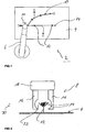
- a processing station 2 comprises a carrier unit 4 designed as a cable board, a manipulator 6, in the exemplary embodiment a multi-axis industrial robot and a processing unit 8 (FIG. Fig. 2 ), which is attached to the manipulator 6, namely a robot hand.
- the manipulator 6 has a plurality of degrees of freedom in order to be able to move the processing unit 8 to any position relative to the carrier unit 4.
- the manipulator 6 offers at least one rotoric degree of freedom, so that the processing unit 8 can be rotated in total with the aid of the manipulator 6.
- the trunk group 10 consists of a plurality of individual lines 14 (FIG. Fig. 2 ). Each of the individual lines 14 is formed in the embodiment by an electrically conductive wire surrounded by an insulation.
- the holding elements 12 are formed in the manner of rod holders with a fork-shaped receptacle in which the individual lines 14 eino. By the holding elements 12, the line bundle 10 is therefore spaced from the surface of a mounting board of the carrier unit 4. As a result, a gripping around of the wire bundle 10 by the processing unit 8 is made possible.
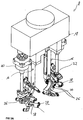
- this has two arms 16, which can be moved in the embodiment by means of a (linear) actuator 18 relative to each other and perpendicular to a machining direction 20.
- a (linear) actuator 18 When closed, the two partial arms 16 define a circular central space 22, in which the cable bundle 10 rests.
- the machining direction 20 is generally defined by the direction in which the machining unit 8 is moved relative to the wire bundle 10. For branches, therefore, the machining direction 20 changes.
- each contact elements 24 are mounted in the embodiment at the ends of the cable set.
- the trunk group 10 has a plurality of branches. Because of these branches, it has not been possible to carry out an automation of the usual banding of the trunk group 10 in an economically meaningful way.
- a special aspect in this case is the basic concept that the processing unit 8 can be brought radially and thus perpendicular to the machining direction 20 to the line bundle 10 and encompass this. In the embodiment, this is made possible by the adjustable arms 16. As soon as a branching point or other obstacle, such as a holding element 12 comes, the partial arms 16 are opened, the processing unit 8 driven over the branch point or the obstacle to then continue with the application of the fixing means with closed part arms 16.
- the manipulator 6 and the processing unit 8 are controlled by means of a control unit, not shown here.
- the processing unit 8 is moved in the machine direction 20 along the wire bundle 10.
- the processing unit 8 first a compression of the individual lines 14, the application of the fixing agent, optionally a structuring of the fixing agent and the curing of the fixing agent.
- the travel speed is preferably a few cm / second to about 10 cm / second, at least in areas without obstacles.
- two linearly mutually adjustable partial arms 16 are provided, each comprising a holmartiges support member, at the end of each a semi-annular machining head is arranged.
- the two semi-annular machining heads form a closed tool head in the closed state of the partial arms 16, which encloses the central space 22 in its interior.
- the term half-ring or annular in connection with the tool head is to be understood here wide and also includes the variants of the Figures 3 and 5 , So is not necessarily limited to a circular cross-sectional geometry of the tool head.
- two functional units are integrated in the tool head, namely an input-side compression unit 26 and an adjoining fixing unit 28.
- a subsequent to the fixing unit 28 curing unit 30 is arranged, which are integrated in this embodiment in a common module.
- the compression unit 26 is identical in all three embodiments and has a plurality of circumferentially arranged to the central space 22 compression elements 32. In the embodiment four pieces are provided. These are formed by rods rotatably mounted on their end side, which are driven by a motor in the central space 22 are pivoted into it. As the individual rods intersect, the cable bundle 10 that is inserted in the central space 22 is compressed and further bundled when pivoting toward the central space 22. For pivoting the rods, a drive mechanism not shown here is provided, which at the end via a toothing between two adjacent compression elements 32 for synchronous movement is transferred to each of two of the compression elements 32, as shown in FIGS FIGS. 4A and 5A easy to recognize.
- the fixing units 28 each include a nozzle 34 through which the fixing agent exits.
- the fixing agent is fed to the individual fixing units 28 via suitable feeds.
- Line connections 36 are provided for the connection of feed hoses for the liquid state fixer in the initial state.
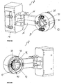
- the nozzles 34 are arranged on the end of pivotally mounted arms 38.
- the lead terminals 36 are provided.
- the pivoting of the arms 38 takes place with the aid of an actuator 40, wherein for each partial arm 16, a separate actuator 40 is provided, which, however, are synchronized with each other.
- the adjusting movement is transmitted from the actuator 40 via a drive axle and a kind of gear transmission to the individual arms 38 for the exercise of the pivoting movement.
- a single fixing unit 28 is provided with only one pivotable arm 38, the arm 38 is in this case formed in the manner of a pan or articulated lever.
- a ring member 39 is provided in the embodiment, which is adjustable in the axial direction and thereby acts on the articulated lever to bring about the desired adjustment.
- the arm 38 is arranged rotatable about the central space 22 around. In the exemplary embodiment, this is made possible by an inner rotor 42 and a drive sprocket 44.
- a rotation of the inner rotor 42 attached to the arm 38 is made possible around the central space 22 around. Due to the Partial arms 16, both the inner rotor 42 and the drive sprocket 44 is formed in two parts.
- module units are arranged approximately in a star shape on the tool head.
- the module units are each attached to a star-shaped support plate by screws.
- Each of the modular units has as a component a fixing unit 28 with a nozzle 34.
- the modular units are, in particular, piezoelectric units, ie the nozzles 34 are designed as piezoelectric nozzles, ie the fixing agent is ejected from the nozzles 34 in a manner known per se with the aid of the piezoelectric effect.
- the curing unit 30, which is formed in this exemplary embodiment by UV light sources 46, is additionally integrated into the respective module unit. These are arranged opposite to the machining direction 20 following the nozzles 34.
Priority Applications (1)
| Application Number | Priority Date | Filing Date | Title |
|---|---|---|---|
| RS20170052A RS55606B1 (sr) | 2011-03-04 | 2011-06-29 | Stanica za obradu u proizvodnji setova kablova, kao i proces automatske proizvodnje setova kablova, kao i jedinica za obradu jedne takve stanice za obradu |
Applications Claiming Priority (2)
| Application Number | Priority Date | Filing Date | Title |
|---|---|---|---|
| DE102011012998 | 2011-03-04 | ||
| PCT/EP2011/003214 WO2012119618A1 (de) | 2011-03-04 | 2011-06-29 | Bearbeitungsstation sowie verfahren zur automatisierten fertigung von kabelsätzen sowie bearbeitungseinheit für eine solche bearbeitungsstation |
Publications (2)
| Publication Number | Publication Date |
|---|---|
| EP2681981A1 EP2681981A1 (de) | 2014-01-08 |
| EP2681981B1 true EP2681981B1 (de) | 2016-10-19 |
Family
ID=44509148
Family Applications (1)
| Application Number | Title | Priority Date | Filing Date |
|---|---|---|---|
| EP11741098.5A Not-in-force EP2681981B1 (de) | 2011-03-04 | 2011-06-29 | Bearbeitungsstation sowie verfahren zur automatisierten fertigung von kabelsätzen sowie bearbeitungseinheit für eine solche bearbeitungsstation |
Country Status (4)
| Country | Link |
|---|---|
| US (1) | US9787042B2 (sr) |
| EP (1) | EP2681981B1 (sr) |
| RS (1) | RS55606B1 (sr) |
| WO (1) | WO2012119618A1 (sr) |
Cited By (1)
| Publication number | Priority date | Publication date | Assignee | Title |
|---|---|---|---|---|
| DE102018218363A1 (de) * | 2018-10-26 | 2020-04-30 | Leoni Bordnetz-Systeme Gmbh | Vorrichtung und Verfahren zum Auftragen einer aushärtbaren Masse |
Families Citing this family (4)
| Publication number | Priority date | Publication date | Assignee | Title |
|---|---|---|---|---|
| US10116422B2 (en) | 2012-11-02 | 2018-10-30 | Qualcomm Incorporated | Managing cross-carrier scheduling in carrier aggregation with EPDCCH in LTE |
| DE102015214929A1 (de) | 2015-08-05 | 2017-02-09 | Leoni Bordnetz-Systeme Gmbh | Kabelsatz und Verfahren zu dessen Herstellung |
| JP6169238B1 (ja) * | 2016-09-21 | 2017-07-26 | 京セラ株式会社 | 電子機器、プログラムおよび制御方法 |
| CN112908565B (zh) * | 2021-01-29 | 2022-05-13 | 广东亚泰科技有限公司 | 线材整理装置及线束加工设备 |
Citations (1)
| Publication number | Priority date | Publication date | Assignee | Title |
|---|---|---|---|---|
| US5851288A (en) * | 1990-10-29 | 1998-12-22 | Gem Gravure Company, Inc. | Apparatus for marking a continuous substrate |
Family Cites Families (5)
| Publication number | Priority date | Publication date | Assignee | Title |
|---|---|---|---|---|
| US3456338A (en) * | 1966-07-11 | 1969-07-22 | Gen Electric | Method for changing the configuration of and for bonding electrical coils of inductive devices |
| JPS6016711B2 (ja) * | 1978-12-11 | 1985-04-26 | 木谷電器株式会社 | プラグ端子付き電線の差込みプラグ成形機への供給装置 |
| DE202007012534U1 (de) | 2007-09-06 | 2007-11-29 | Selbach, Dirk | Kabelbaumfertigungsfeld |
| US8146491B2 (en) | 2008-04-29 | 2012-04-03 | Newfrey Llc | Apparatus and method for automatically, circumferentially wrapping a cable harness |
| DE102008022337A1 (de) * | 2008-04-29 | 2009-11-05 | Newfrey Llc, Newark | Vorrichtung und Verfahren zum automatisierten umfänglichen Umwickeln eines Kabelbaums mit einem Befestigungssystem bestehend aus einem Befestigungselement und einem Wickelband |
-
2011
- 2011-06-29 RS RS20170052A patent/RS55606B1/sr unknown
- 2011-06-29 WO PCT/EP2011/003214 patent/WO2012119618A1/de active Application Filing
- 2011-06-29 EP EP11741098.5A patent/EP2681981B1/de not_active Not-in-force
-
2013
- 2013-09-04 US US14/017,863 patent/US9787042B2/en active Active
Patent Citations (1)
| Publication number | Priority date | Publication date | Assignee | Title |
|---|---|---|---|---|
| US5851288A (en) * | 1990-10-29 | 1998-12-22 | Gem Gravure Company, Inc. | Apparatus for marking a continuous substrate |
Cited By (2)
| Publication number | Priority date | Publication date | Assignee | Title |
|---|---|---|---|---|
| DE102018218363A1 (de) * | 2018-10-26 | 2020-04-30 | Leoni Bordnetz-Systeme Gmbh | Vorrichtung und Verfahren zum Auftragen einer aushärtbaren Masse |
| DE102018218363B4 (de) | 2018-10-26 | 2020-06-04 | Leoni Bordnetz-Systeme Gmbh | Vorrichtung und Verfahren zum Auftragen einer aushärtbaren Masse |
Also Published As
| Publication number | Publication date |
|---|---|
| EP2681981A1 (de) | 2014-01-08 |
| WO2012119618A1 (de) | 2012-09-13 |
| US9787042B2 (en) | 2017-10-10 |
| US20140013596A1 (en) | 2014-01-16 |
| RS55606B1 (sr) | 2017-06-30 |
Similar Documents
| Publication | Publication Date | Title |
|---|---|---|
| EP2681981B1 (de) | Bearbeitungsstation sowie verfahren zur automatisierten fertigung von kabelsätzen sowie bearbeitungseinheit für eine solche bearbeitungsstation | |
| EP1713153B1 (de) | Leitungsverbund | |
| EP1761982B1 (de) | Vorrichtung mit zwei relativ zueinander beweglichen teilen sowie schleppkettenanordnung | |
| EP3503127B1 (de) | Wickelvorrichtung und verfahren zum vollautomatisierten umwickeln eines leitungsbündels mit einem klebeband | |
| EP3542376B1 (de) | Verfahren und vorrichtung zur herstellung einer ummantelung für elektrische kabel | |
| DE102018106980A1 (de) | Vorrichtung und Verfahren zum Biegen von Draht für die Herstellung von Maschinenelementen elektrischer Maschinen | |
| DE3606059C2 (sr) | ||
| EP3774172B1 (de) | Verfahren zur montage eines ringförmigen dichtungselements | |
| EP3727783B1 (de) | Vorrichtung zur herstellung einer ummantelung für kabel | |
| DE102007019509B3 (de) | Vorrichtung zum Beschichten der Innenwand eines Hohlkörpers | |
| EP3235399B1 (de) | Verfahren und vorrichtung zum selektiven auftragen eines abdecklackes | |
| EP3211773B1 (de) | Verfahren zur herstellung eines stators durch nadelwickeln | |
| DE102016119867B4 (de) | Kabelbaumformbrett und Verfahren zur Herstellung eines Leitungssatzes | |
| DE102007048254A1 (de) | Verfahren und Vorrichtung zum Erzeugen von Spulenwickeln | |
| EP2422946B1 (de) | Übertragungseinrichtung für Strahlung | |
| WO2021047851A1 (de) | Vorrichtung sowie verfahren zur automatisierten befestigung von tüllen an einem leitungsstrang | |
| DE3915854C2 (sr) | ||
| DE102006056230B4 (de) | Vorrichtung zum Innenbeschichten eines Hohlkörpers | |
| DE19606643A1 (de) | Befestigungseinrichtung für Kabelbäume, Verfahren zu deren Herstellung und Verwendung der Befestigungseinrichtung | |
| DE19645872C2 (de) | Vorrichtung zum Aufbringen von Dichtungsmassen auf unrunde Deckelrandkonturen | |
| DE102018211560A1 (de) | Vorrichtung zum Anbringen einer Türdichtung an eine Tür | |
| DE102018218363B4 (de) | Vorrichtung und Verfahren zum Auftragen einer aushärtbaren Masse | |
| DE3727240C2 (de) | Verfahren und Vorrichtung zum Bündeln von Kabelsträngen | |
| WO1989012900A1 (en) | A method and device for producing wiring harnesses | |
| DE102012020624A1 (de) | Führungsvorrichtung zum Führen einer Mehrzahl von Fäden zur Herstellung eines Faserverbundbauteils |
Legal Events
| Date | Code | Title | Description |
|---|---|---|---|
| PUAI | Public reference made under article 153(3) epc to a published international application that has entered the european phase |
Free format text: ORIGINAL CODE: 0009012 |
|
| 17P | Request for examination filed |
Effective date: 20130821 |
|
| AK | Designated contracting states |
Kind code of ref document: A1 Designated state(s): AL AT BE BG CH CY CZ DE DK EE ES FI FR GB GR HR HU IE IS IT LI LT LU LV MC MK MT NL NO PL PT RO RS SE SI SK SM TR |
|
| DAX | Request for extension of the european patent (deleted) | ||
| 17Q | First examination report despatched |
Effective date: 20150812 |
|
| GRAP | Despatch of communication of intention to grant a patent |
Free format text: ORIGINAL CODE: EPIDOSNIGR1 |
|
| INTG | Intention to grant announced |
Effective date: 20160517 |
|
| GRAS | Grant fee paid |
Free format text: ORIGINAL CODE: EPIDOSNIGR3 |
|
| GRAA | (expected) grant |
Free format text: ORIGINAL CODE: 0009210 |
|
| AK | Designated contracting states |
Kind code of ref document: B1 Designated state(s): AL AT BE BG CH CY CZ DE DK EE ES FI FR GB GR HR HU IE IS IT LI LT LU LV MC MK MT NL NO PL PT RO RS SE SI SK SM TR |
|
| REG | Reference to a national code |
Ref country code: GB Ref legal event code: FG4D Free format text: NOT ENGLISH |
|
| REG | Reference to a national code |
Ref country code: CH Ref legal event code: EP |
|
| REG | Reference to a national code |
Ref country code: AT Ref legal event code: REF Ref document number: 839280 Country of ref document: AT Kind code of ref document: T Effective date: 20161115 |
|
| REG | Reference to a national code |
Ref country code: IE Ref legal event code: FG4D Free format text: LANGUAGE OF EP DOCUMENT: GERMAN |
|
| REG | Reference to a national code |
Ref country code: DE Ref legal event code: R096 Ref document number: 502011010959 Country of ref document: DE |
|
| REG | Reference to a national code |
Ref country code: CH Ref legal event code: NV Representative=s name: E. BLUM AND CO. AG PATENT- UND MARKENANWAELTE , CH |
|
| REG | Reference to a national code |
Ref country code: NL Ref legal event code: MP Effective date: 20161019 |
|
| REG | Reference to a national code |
Ref country code: LT Ref legal event code: MG4D |
|
| PG25 | Lapsed in a contracting state [announced via postgrant information from national office to epo] |
Ref country code: LV Free format text: LAPSE BECAUSE OF FAILURE TO SUBMIT A TRANSLATION OF THE DESCRIPTION OR TO PAY THE FEE WITHIN THE PRESCRIBED TIME-LIMIT Effective date: 20161019 |
|
| PG25 | Lapsed in a contracting state [announced via postgrant information from national office to epo] |
Ref country code: LT Free format text: LAPSE BECAUSE OF FAILURE TO SUBMIT A TRANSLATION OF THE DESCRIPTION OR TO PAY THE FEE WITHIN THE PRESCRIBED TIME-LIMIT Effective date: 20161019 Ref country code: GR Free format text: LAPSE BECAUSE OF FAILURE TO SUBMIT A TRANSLATION OF THE DESCRIPTION OR TO PAY THE FEE WITHIN THE PRESCRIBED TIME-LIMIT Effective date: 20170120 Ref country code: SE Free format text: LAPSE BECAUSE OF FAILURE TO SUBMIT A TRANSLATION OF THE DESCRIPTION OR TO PAY THE FEE WITHIN THE PRESCRIBED TIME-LIMIT Effective date: 20161019 Ref country code: NO Free format text: LAPSE BECAUSE OF FAILURE TO SUBMIT A TRANSLATION OF THE DESCRIPTION OR TO PAY THE FEE WITHIN THE PRESCRIBED TIME-LIMIT Effective date: 20170119 |
|
| PG25 | Lapsed in a contracting state [announced via postgrant information from national office to epo] |
Ref country code: HR Free format text: LAPSE BECAUSE OF FAILURE TO SUBMIT A TRANSLATION OF THE DESCRIPTION OR TO PAY THE FEE WITHIN THE PRESCRIBED TIME-LIMIT Effective date: 20161019 Ref country code: FI Free format text: LAPSE BECAUSE OF FAILURE TO SUBMIT A TRANSLATION OF THE DESCRIPTION OR TO PAY THE FEE WITHIN THE PRESCRIBED TIME-LIMIT Effective date: 20161019 Ref country code: ES Free format text: LAPSE BECAUSE OF FAILURE TO SUBMIT A TRANSLATION OF THE DESCRIPTION OR TO PAY THE FEE WITHIN THE PRESCRIBED TIME-LIMIT Effective date: 20161019 Ref country code: PL Free format text: LAPSE BECAUSE OF FAILURE TO SUBMIT A TRANSLATION OF THE DESCRIPTION OR TO PAY THE FEE WITHIN THE PRESCRIBED TIME-LIMIT Effective date: 20161019 Ref country code: IS Free format text: LAPSE BECAUSE OF FAILURE TO SUBMIT A TRANSLATION OF THE DESCRIPTION OR TO PAY THE FEE WITHIN THE PRESCRIBED TIME-LIMIT Effective date: 20170219 Ref country code: PT Free format text: LAPSE BECAUSE OF FAILURE TO SUBMIT A TRANSLATION OF THE DESCRIPTION OR TO PAY THE FEE WITHIN THE PRESCRIBED TIME-LIMIT Effective date: 20170220 Ref country code: NL Free format text: LAPSE BECAUSE OF FAILURE TO SUBMIT A TRANSLATION OF THE DESCRIPTION OR TO PAY THE FEE WITHIN THE PRESCRIBED TIME-LIMIT Effective date: 20161019 |
|
| REG | Reference to a national code |
Ref country code: RO Ref legal event code: EPE |
|
| REG | Reference to a national code |
Ref country code: DE Ref legal event code: R097 Ref document number: 502011010959 Country of ref document: DE |
|
| PG25 | Lapsed in a contracting state [announced via postgrant information from national office to epo] |
Ref country code: CZ Free format text: LAPSE BECAUSE OF FAILURE TO SUBMIT A TRANSLATION OF THE DESCRIPTION OR TO PAY THE FEE WITHIN THE PRESCRIBED TIME-LIMIT Effective date: 20161019 Ref country code: EE Free format text: LAPSE BECAUSE OF FAILURE TO SUBMIT A TRANSLATION OF THE DESCRIPTION OR TO PAY THE FEE WITHIN THE PRESCRIBED TIME-LIMIT Effective date: 20161019 Ref country code: SK Free format text: LAPSE BECAUSE OF FAILURE TO SUBMIT A TRANSLATION OF THE DESCRIPTION OR TO PAY THE FEE WITHIN THE PRESCRIBED TIME-LIMIT Effective date: 20161019 Ref country code: DK Free format text: LAPSE BECAUSE OF FAILURE TO SUBMIT A TRANSLATION OF THE DESCRIPTION OR TO PAY THE FEE WITHIN THE PRESCRIBED TIME-LIMIT Effective date: 20161019 |
|
| RAP2 | Party data changed (patent owner data changed or rights of a patent transferred) |
Owner name: LEONI BORDNETZ-SYSTEME GMBH |
|
| PLBE | No opposition filed within time limit |
Free format text: ORIGINAL CODE: 0009261 |
|
| STAA | Information on the status of an ep patent application or granted ep patent |
Free format text: STATUS: NO OPPOSITION FILED WITHIN TIME LIMIT |
|
| PG25 | Lapsed in a contracting state [announced via postgrant information from national office to epo] |
Ref country code: IT Free format text: LAPSE BECAUSE OF FAILURE TO SUBMIT A TRANSLATION OF THE DESCRIPTION OR TO PAY THE FEE WITHIN THE PRESCRIBED TIME-LIMIT Effective date: 20161019 Ref country code: SM Free format text: LAPSE BECAUSE OF FAILURE TO SUBMIT A TRANSLATION OF THE DESCRIPTION OR TO PAY THE FEE WITHIN THE PRESCRIBED TIME-LIMIT Effective date: 20161019 Ref country code: BG Free format text: LAPSE BECAUSE OF FAILURE TO SUBMIT A TRANSLATION OF THE DESCRIPTION OR TO PAY THE FEE WITHIN THE PRESCRIBED TIME-LIMIT Effective date: 20170119 |
|
| 26N | No opposition filed |
Effective date: 20170720 |
|
| PG25 | Lapsed in a contracting state [announced via postgrant information from national office to epo] |
Ref country code: SI Free format text: LAPSE BECAUSE OF FAILURE TO SUBMIT A TRANSLATION OF THE DESCRIPTION OR TO PAY THE FEE WITHIN THE PRESCRIBED TIME-LIMIT Effective date: 20161019 |
|
| PG25 | Lapsed in a contracting state [announced via postgrant information from national office to epo] |
Ref country code: MC Free format text: LAPSE BECAUSE OF FAILURE TO SUBMIT A TRANSLATION OF THE DESCRIPTION OR TO PAY THE FEE WITHIN THE PRESCRIBED TIME-LIMIT Effective date: 20161019 |
|
| GBPC | Gb: european patent ceased through non-payment of renewal fee |
Effective date: 20170629 |
|
| REG | Reference to a national code |
Ref country code: FR Ref legal event code: ST Effective date: 20180228 |
|
| REG | Reference to a national code |
Ref country code: IE Ref legal event code: MM4A |
|
| PG25 | Lapsed in a contracting state [announced via postgrant information from national office to epo] |
Ref country code: LU Free format text: LAPSE BECAUSE OF NON-PAYMENT OF DUE FEES Effective date: 20170629 Ref country code: IE Free format text: LAPSE BECAUSE OF NON-PAYMENT OF DUE FEES Effective date: 20170629 Ref country code: GB Free format text: LAPSE BECAUSE OF NON-PAYMENT OF DUE FEES Effective date: 20170629 |
|
| PG25 | Lapsed in a contracting state [announced via postgrant information from national office to epo] |
Ref country code: FR Free format text: LAPSE BECAUSE OF NON-PAYMENT OF DUE FEES Effective date: 20170630 |
|
| REG | Reference to a national code |
Ref country code: BE Ref legal event code: MM Effective date: 20170630 |
|
| REG | Reference to a national code |
Ref country code: AT Ref legal event code: MM01 Ref document number: 839280 Country of ref document: AT Kind code of ref document: T Effective date: 20170629 |
|
| PG25 | Lapsed in a contracting state [announced via postgrant information from national office to epo] |
Ref country code: BE Free format text: LAPSE BECAUSE OF NON-PAYMENT OF DUE FEES Effective date: 20170630 |
|
| PG25 | Lapsed in a contracting state [announced via postgrant information from national office to epo] |
Ref country code: MT Free format text: LAPSE BECAUSE OF FAILURE TO SUBMIT A TRANSLATION OF THE DESCRIPTION OR TO PAY THE FEE WITHIN THE PRESCRIBED TIME-LIMIT Effective date: 20161019 |
|
| PG25 | Lapsed in a contracting state [announced via postgrant information from national office to epo] |
Ref country code: AT Free format text: LAPSE BECAUSE OF NON-PAYMENT OF DUE FEES Effective date: 20170629 |
|
| PG25 | Lapsed in a contracting state [announced via postgrant information from national office to epo] |
Ref country code: HU Free format text: LAPSE BECAUSE OF FAILURE TO SUBMIT A TRANSLATION OF THE DESCRIPTION OR TO PAY THE FEE WITHIN THE PRESCRIBED TIME-LIMIT; INVALID AB INITIO Effective date: 20110629 |
|
| PG25 | Lapsed in a contracting state [announced via postgrant information from national office to epo] |
Ref country code: CY Free format text: LAPSE BECAUSE OF NON-PAYMENT OF DUE FEES Effective date: 20161019 |
|
| PG25 | Lapsed in a contracting state [announced via postgrant information from national office to epo] |
Ref country code: MK Free format text: LAPSE BECAUSE OF FAILURE TO SUBMIT A TRANSLATION OF THE DESCRIPTION OR TO PAY THE FEE WITHIN THE PRESCRIBED TIME-LIMIT Effective date: 20161019 |
|
| PG25 | Lapsed in a contracting state [announced via postgrant information from national office to epo] |
Ref country code: TR Free format text: LAPSE BECAUSE OF FAILURE TO SUBMIT A TRANSLATION OF THE DESCRIPTION OR TO PAY THE FEE WITHIN THE PRESCRIBED TIME-LIMIT Effective date: 20161019 |
|
| PG25 | Lapsed in a contracting state [announced via postgrant information from national office to epo] |
Ref country code: AL Free format text: LAPSE BECAUSE OF FAILURE TO SUBMIT A TRANSLATION OF THE DESCRIPTION OR TO PAY THE FEE WITHIN THE PRESCRIBED TIME-LIMIT Effective date: 20161019 |
|
| PGFP | Annual fee paid to national office [announced via postgrant information from national office to epo] |
Ref country code: RO Payment date: 20210622 Year of fee payment: 11 Ref country code: DE Payment date: 20210621 Year of fee payment: 11 |
|
| PGFP | Annual fee paid to national office [announced via postgrant information from national office to epo] |
Ref country code: CH Payment date: 20210623 Year of fee payment: 11 |
|
| PGFP | Annual fee paid to national office [announced via postgrant information from national office to epo] |
Ref country code: RS Payment date: 20210625 Year of fee payment: 11 |
|
| REG | Reference to a national code |
Ref country code: DE Ref legal event code: R119 Ref document number: 502011010959 Country of ref document: DE |
|
| PG25 | Lapsed in a contracting state [announced via postgrant information from national office to epo] |
Ref country code: RO Free format text: LAPSE BECAUSE OF NON-PAYMENT OF DUE FEES Effective date: 20220629 |
|
| REG | Reference to a national code |
Ref country code: CH Ref legal event code: PL |
|
| PG25 | Lapsed in a contracting state [announced via postgrant information from national office to epo] |
Ref country code: LI Free format text: LAPSE BECAUSE OF NON-PAYMENT OF DUE FEES Effective date: 20220630 Ref country code: CH Free format text: LAPSE BECAUSE OF NON-PAYMENT OF DUE FEES Effective date: 20220630 |
|
| PG25 | Lapsed in a contracting state [announced via postgrant information from national office to epo] |
Ref country code: RS Free format text: LAPSE BECAUSE OF NON-PAYMENT OF DUE FEES Effective date: 20220629 Ref country code: DE Free format text: LAPSE BECAUSE OF NON-PAYMENT OF DUE FEES Effective date: 20230103 |