EP2681981B1 - Processing station and method for the automated manufacture of cable harnesses and processing unit for such a processing station - Google Patents
Processing station and method for the automated manufacture of cable harnesses and processing unit for such a processing station Download PDFInfo
- Publication number
- EP2681981B1 EP2681981B1 EP11741098.5A EP11741098A EP2681981B1 EP 2681981 B1 EP2681981 B1 EP 2681981B1 EP 11741098 A EP11741098 A EP 11741098A EP 2681981 B1 EP2681981 B1 EP 2681981B1
- Authority
- EP
- European Patent Office
- Prior art keywords
- unit
- processing unit
- cable bundle
- processing station
- fixing agent
- Prior art date
- Legal status (The legal status is an assumption and is not a legal conclusion. Google has not performed a legal analysis and makes no representation as to the accuracy of the status listed.)
- Not-in-force
Links
Images


Classifications
-
- H—ELECTRICITY
- H01—ELECTRIC ELEMENTS
- H01R—ELECTRICALLY-CONDUCTIVE CONNECTIONS; STRUCTURAL ASSOCIATIONS OF A PLURALITY OF MUTUALLY-INSULATED ELECTRICAL CONNECTING ELEMENTS; COUPLING DEVICES; CURRENT COLLECTORS
- H01R43/00—Apparatus or processes specially adapted for manufacturing, assembling, maintaining, or repairing of line connectors or current collectors or for joining electric conductors
-
- H—ELECTRICITY
- H01—ELECTRIC ELEMENTS
- H01B—CABLES; CONDUCTORS; INSULATORS; SELECTION OF MATERIALS FOR THEIR CONDUCTIVE, INSULATING OR DIELECTRIC PROPERTIES
- H01B13/00—Apparatus or processes specially adapted for manufacturing conductors or cables
- H01B13/012—Apparatus or processes specially adapted for manufacturing conductors or cables for manufacturing wire harnesses
- H01B13/01263—Tying, wrapping, binding, lacing, strapping or sheathing harnesses
- H01B13/01272—Harness tying apparatus
-
- H—ELECTRICITY
- H05—ELECTRIC TECHNIQUES NOT OTHERWISE PROVIDED FOR
- H05K—PRINTED CIRCUITS; CASINGS OR CONSTRUCTIONAL DETAILS OF ELECTRIC APPARATUS; MANUFACTURE OF ASSEMBLAGES OF ELECTRICAL COMPONENTS
- H05K13/00—Apparatus or processes specially adapted for manufacturing or adjusting assemblages of electric components
- H05K13/06—Wiring by machine
- H05K13/065—Accessories therefor, e.g. light spots
-
- H—ELECTRICITY
- H01—ELECTRIC ELEMENTS
- H01B—CABLES; CONDUCTORS; INSULATORS; SELECTION OF MATERIALS FOR THEIR CONDUCTIVE, INSULATING OR DIELECTRIC PROPERTIES
- H01B13/00—Apparatus or processes specially adapted for manufacturing conductors or cables
- H01B13/0036—Details
-
- Y—GENERAL TAGGING OF NEW TECHNOLOGICAL DEVELOPMENTS; GENERAL TAGGING OF CROSS-SECTIONAL TECHNOLOGIES SPANNING OVER SEVERAL SECTIONS OF THE IPC; TECHNICAL SUBJECTS COVERED BY FORMER USPC CROSS-REFERENCE ART COLLECTIONS [XRACs] AND DIGESTS
- Y10—TECHNICAL SUBJECTS COVERED BY FORMER USPC
- Y10T—TECHNICAL SUBJECTS COVERED BY FORMER US CLASSIFICATION
- Y10T29/00—Metal working
- Y10T29/49—Method of mechanical manufacture
- Y10T29/49002—Electrical device making
- Y10T29/49117—Conductor or circuit manufacturing
-
- Y—GENERAL TAGGING OF NEW TECHNOLOGICAL DEVELOPMENTS; GENERAL TAGGING OF CROSS-SECTIONAL TECHNOLOGIES SPANNING OVER SEVERAL SECTIONS OF THE IPC; TECHNICAL SUBJECTS COVERED BY FORMER USPC CROSS-REFERENCE ART COLLECTIONS [XRACs] AND DIGESTS
- Y10—TECHNICAL SUBJECTS COVERED BY FORMER USPC
- Y10T—TECHNICAL SUBJECTS COVERED BY FORMER US CLASSIFICATION
- Y10T29/00—Metal working
- Y10T29/53—Means to assemble or disassemble
- Y10T29/5313—Means to assemble electrical device
- Y10T29/532—Conductor
- Y10T29/53243—Multiple, independent conductors
Definitions
- the invention relates to a processing station and to a method for the automated production of cable sets consisting of a plurality of individual lines with the preambles of claim 1 and of claim 14.
- the invention further relates to a processing unit for such a processing station.
- Under cable set is generally understood a prefabricated trunk group, in which a plurality of individual lines according to a predefined course or layout and are connected to each other in a defined length.
- Cordsets usually have a branched structure with a plurality of branches or branches.
- the individual cables have a limited length, the cable set is therefore a total of a prefabricated, prefabricated cargo.
- At the individual ends of the individual lines often contact elements such as plugs or the like are posted.
- Such cable sets are used in particular in the automotive industry, for example for the electrical connection of a plurality of consumers with a central distribution or control unit.
- banding there are different possibilities, namely a so-called full banding, in which the cable bundle is completely surrounded by the banding or also a so-called savings banding, in which the cable bundle is surrounded only at partial areas of the banding.
- a so-called full banding in which the cable bundle is completely surrounded by the banding
- a so-called savings banding in which the cable bundle is surrounded only at partial areas of the banding.
- special tapes or banding namely so-called loop bands are used.
- the banding therefore has different functions depending on the location of the cable set. The main function is the connection of the individual cables.
- the banding is often used for attachment of support elements or additional elements.
- the banding serves as a mechanical protection, as rattle protection etc.
- the trunk group is surrounded at least in some areas with a foamed body, for example, to form a so-called dimensionally stable cable set, in which the branches and branches are fixed in their geometry.
- the cable bundle is usually inserted into a mold (foam mold) into which a foamable material, such as a PU material is then introduced.
- a cable set typically has only very short rectilinear portions without ramifications, which are usually only in the range of up to several 10 cm.
- the invention has the object to enable automated assembly of the individual cables for the production of a cable set.
- the object is achieved according to the invention by a processing station having the features of claim 1, by a processing unit having the features of claim 12 and by a method having the features of claim 14.
- a loose cable bundle consisting of the individual cables, which has a predetermined and branched course with usually a multiplicity of branches and branchings, is held by a carrier unit, at this prefixed.
- loose cable bundle here is the juxtaposition of the individual lines according to the intended course understood without banding or the like.
- the individual lines are therefore loosely next to each other, are at best prefixed by holding elements of the carrier unit.
- the individual lines are automatically fixed to one another in the manner of a banding with the aid of a processing unit.
- the processing unit has a fixing unit, which applies a fixing means to the loose line bundle, so that the individual lines are connected to one another by the fixing means.
- the fixer therefore replaces the banding.
- the processing unit and the wire bundle are preferably moved relative to one another in a processing direction along the wire bundle with the aid of a manipulator.
- the carrier unit is preferably designed in the manner of a conventional mounting or cable board and has - depending on the size of the cable set - an area of up to a few m 2 , on the line bundle according to the intended course, ie the intended branched and ramified geometry of the cable set is relocated.
- the individual lines are usually insulated conductor wires made of a conductive material such as copper, aluminum or alloys thereof.
- the carrier unit preferably has rod holders which, for example, form a forked or semi-annular receptacle at the end, into which the cable bundle is inserted.
- the cable bundle is therefore kept at a distance from a plane, for example a plate-like carrier, so that it can be fully encompassed by the processing unit.
- the manipulator is, for example, an actuator, which can move the processing unit in the xyz direction and, in particular, additionally allows rotation about the axis defined by the machining direction.
- the manipulator is a robot arm of a multi-axis industrial robot, for example a so-called 6-axis industrial robot. With this a variety of degrees of freedom is possible. As a result, a high degree of design freedom and high flexibility is achieved, which is particularly advantageous for the different requirements and designs or types of cable sets.
- the processing unit is preferably guided by a robot hand of a multi-axis industrial robot.
- the processing unit is preferably guided by a robot hand of a multi-axis industrial robot.
- the fixing agent has a liquid or viscous consistency during application and cures after application to the wire bundle. As a result, a reliable application of the fixing is possible. After curing, the fixing agent surrounds the cable bundle preferably in the manner of a band or a jacket and holds in this way the individual lines together.
- the fixing agent used is a hardenable plastic resin.
- This can also be a two-component system.
- Curable resin systems are widely known.
- a suitable resin system is selected which, on the one hand, enables process-reliable processing and which, on the other hand, cures as quickly as possible, preferably immediately after application, in order to allow the highest possible process speeds.
- a traveling speed of the processing unit relative to the wire bundle of 100 mm per second is provided, i. the resin system must allow a sufficiently fast cure.
- the curing process is completed at least to a large extent as soon as the processing unit has completely crossed over the respective location of the cable bundle. The curing of the resin therefore takes place virtually instantaneously immediately after application to the cable bundle.
- the processing unit is designed for at least partially encompassing the line bundle, so that the processing unit can be approached in the radial direction to the line bundle during the machining process.
- the processing unit preferably has at least two mutually movable partial arms which, in the closed state, embrace the individual lines preferably completely in the manner of a ring.
- the two partial arms are preferably displaceable relative to one another by means of an adjusting element, for example a linear drive, or also connected to one another via a hinge connection.
- the two arms are preferably lockable with each other via a closure designed in the manner of a bayonet closure.
- the processing unit C- or U-shaped so that over the open area, the trunk group can be inserted into the central space defined by the processing unit.
- This embodiment allows an efficient, reliable application of the fixing agent even with the complex cable harness geometries with multiple branches.
- this also obstacles, such as those formed by the rod holders, are taken into account by either the opening of the fork-shaped processing unit is brought into a corresponding orientation position, or by the two arms are slightly opened.
- the two partial arms are formed symmetrically with respect to a parting plane and have the same components.
- each of the partial arms has the same components, in particular one or more fixing units and / or compression units and / or curing units.
- the use of several different fixing means is provided in addition, so that - depending on the requirements - either with a cable bundle or with different cable bundles different fixatives can be used without a tool change is required.
- the individual nozzles and any curing units are preferably adapted to the respective resin system.
- the processing station therefore comprises a plurality of storage containers for the different fixing means (different resin systems).
- a structuring of the applied fixing agent by applying flocking material such as fibers or other solid particles is generally provided.
- the desired properties are set, for example suitable for scuff protection or sound insulation.
- so-called "loop dispensers" can be modeled.
- resin or paint systems are used, which have sufficient rigidity and hardness after curing, for example, perform the entire trunk group, at least in areas dimensionally stable.
- fixative components such as clips or Einsteckpins (to be plugged into boreholes in a sheet metal component to form).
- At least one nozzle or metering needle is expediently provided as a fixing unit or as part of the fixing unit.
- a plurality of nozzles are provided, which are arranged distributed in the circumferential direction, that is lying on a circle or a circular arc.
- the nozzles preferably enclose the cable bundle at least substantially annularly.
- the nozzles are preferably controllable nozzles, which are opened and closed via control signals which are predetermined by a control unit.
- This allows a very flexible application of the fixing agent with different application rates and in particular allows the application of the fixing agent on the type of different types of tape, for example, a full banding or a savings banding, in which the fixing agent is applied helically to the cable bundle. This is achieved for example by a successive activation of the distributed nozzles. Alternatively or additionally, this is achieved by a rotational movement of the at least one nozzle.
- a plurality of nozzles is preferably provided, which are arranged in the manner of an array, for example annular or semi-annular.
- the nozzles are preferably designed as slot nozzles.
- the nozzles are designed according to a preferred variant as piezoelectric nozzles or piezoelectric doser, the ejection of the fixing agent is therefore carried out with the aid of the piezoelectric effect.
- the processing unit as a whole is moved in the circumferential direction around the wire bundle around for the exercise of the rotation.
- Cable sets are generally characterized by a very high diversity and high variability in terms of their complexity and size.
- a controlled radial delivery of the nozzles is provided in the direction towards a central axis.
- the nozzle can always be brought in an optimal distance to the wire bundle.
- the nozzle is mounted on a rocker arm, so that the feed movement takes place in the radial direction by means of a pivoting movement.
- a common drive In the arrangement of a plurality of nozzles preferably more of the nozzles are coupled together via a common drive, so that a synchronous movement of the nozzles takes place.
- a curing unit is attached to the processing unit.
- the processing unit is therefore designed to be multifunctional overall and, in addition to the function of applying the fixing agent, also has the function of hardening.
- different curing units can be provided here.
- a light source in particular a UV light source, is provided, which irradiates the applied fixing agent.
- each individual nozzle is assigned its own curing unit or its own curing element, such as a light source.
- a heat source is expediently arranged, for example an infrared radiation source.
- the curing unit is a gas flow unit is formed, via which a gas is passed with overpressure in the direction of the applied fixing agent.
- gas nozzles are expediently provided.
- approximately punctiform nozzles in an alternative embodiment, a large-area flow opening is provided which extends along at least a portion of the circumference along a circular arc line.
- an annular nozzle is provided to form an annular flow jacket.
- a fan for generating the gas flow and / or a pressurized gas source is therefore also provided in particular.
- it is connected to a gas supply system.
- the gas is pressed with a sufficient overpressure, for example of a few bar, against the fixing agent, so that this also penetrates a little way into the interior of the line bundle, so that a more intensive connection of the individual lines is achieved.
- the gas inflow is expediently used alternatively or additionally also for structuring the fixing agent, ie the applied fixing agent is displaced in a certain way after application by the gas flow, so that, for example, regions with different material thickness are formed.
- this allows an oscillating, wave-like surface structure form the fixing agent.
- a corrugated tube property can be brought about in some way with radially projecting ribs.
- This structuring with variable material thickness of the fixing agent can generally also be carried out without the gas supply unit.
- a separate, additional gas supply unit with a corresponding nozzle arrangement to the curing unit is provided, which is connected upstream of the curing unit.
- a compression unit is provided, with the aid of which the individual lines are compressed prior to the application of the fixing agent and compressed to form a bundle with a defined diameter.
- the compression unit is designed such that the individual lines are compressed in the radial direction, preferably at least substantially concentrically about a central or central axis.
- the compression unit preferably has individual compression elements which are distributed around the circumference.
- the individual compression elements are designed, for example, as circular arc segments or ring segments which can be moved in the radial direction, for example with the aid of a punch.
- the compression elements are offset by means of a pivoting movement in the radial direction. They are therefore pivotally mounted at the edge of the processing unit.
- the drive takes place via a suitable, controllable drive unit.
- the compression elements are designed as simple rods. The movements of the individual compression elements are coordinated to achieve concentric compression.
- the compression unit is expediently part of the processing unit. This has in particular the units fixing unit and compression unit. If necessary and in appropriate training is also the third Functional unit, namely the curing unit, integrated in the processing unit.
- the processing unit is designed in the manner of a uniform tool head, which is moved along the line bundle. With only one sweep of the wire bundle using this processing unit, therefore, the individual lines are first compressed, then the fixing agent is applied and then the curing takes place.
- the individual functional units follow each other directly.
- the processing unit has a carrier on which - viewed in the machining direction - the compression unit is arranged on the input side, then the fixing unit and finally the curing unit are arranged on the input side.
- a very compact design is achieved overall and high process speeds are also possible. This compact design allows easy handling even with complex cable harness geometries. Due to the compact design, the processing unit, ie the individual functional units can be brought very close to the trunk group in the range of branches.
- All functional units are integrated within the processing unit designed in the manner of a tool head. This is preferably designed to encompass the cable bundle and in particular of two partial arms.
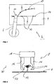
- a processing station 2 comprises a carrier unit 4 designed as a cable board, a manipulator 6, in the exemplary embodiment a multi-axis industrial robot and a processing unit 8 (FIG. Fig. 2 ), which is attached to the manipulator 6, namely a robot hand.
- the manipulator 6 has a plurality of degrees of freedom in order to be able to move the processing unit 8 to any position relative to the carrier unit 4.
- the manipulator 6 offers at least one rotoric degree of freedom, so that the processing unit 8 can be rotated in total with the aid of the manipulator 6.
- the trunk group 10 consists of a plurality of individual lines 14 (FIG. Fig. 2 ). Each of the individual lines 14 is formed in the embodiment by an electrically conductive wire surrounded by an insulation.
- the holding elements 12 are formed in the manner of rod holders with a fork-shaped receptacle in which the individual lines 14 eino. By the holding elements 12, the line bundle 10 is therefore spaced from the surface of a mounting board of the carrier unit 4. As a result, a gripping around of the wire bundle 10 by the processing unit 8 is made possible.
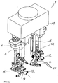
- this has two arms 16, which can be moved in the embodiment by means of a (linear) actuator 18 relative to each other and perpendicular to a machining direction 20.
- a (linear) actuator 18 When closed, the two partial arms 16 define a circular central space 22, in which the cable bundle 10 rests.
- the machining direction 20 is generally defined by the direction in which the machining unit 8 is moved relative to the wire bundle 10. For branches, therefore, the machining direction 20 changes.
- each contact elements 24 are mounted in the embodiment at the ends of the cable set.
- the trunk group 10 has a plurality of branches. Because of these branches, it has not been possible to carry out an automation of the usual banding of the trunk group 10 in an economically meaningful way.
- a special aspect in this case is the basic concept that the processing unit 8 can be brought radially and thus perpendicular to the machining direction 20 to the line bundle 10 and encompass this. In the embodiment, this is made possible by the adjustable arms 16. As soon as a branching point or other obstacle, such as a holding element 12 comes, the partial arms 16 are opened, the processing unit 8 driven over the branch point or the obstacle to then continue with the application of the fixing means with closed part arms 16.
- the manipulator 6 and the processing unit 8 are controlled by means of a control unit, not shown here.
- the processing unit 8 is moved in the machine direction 20 along the wire bundle 10.
- the processing unit 8 first a compression of the individual lines 14, the application of the fixing agent, optionally a structuring of the fixing agent and the curing of the fixing agent.
- the travel speed is preferably a few cm / second to about 10 cm / second, at least in areas without obstacles.
- two linearly mutually adjustable partial arms 16 are provided, each comprising a holmartiges support member, at the end of each a semi-annular machining head is arranged.
- the two semi-annular machining heads form a closed tool head in the closed state of the partial arms 16, which encloses the central space 22 in its interior.
- the term half-ring or annular in connection with the tool head is to be understood here wide and also includes the variants of the Figures 3 and 5 , So is not necessarily limited to a circular cross-sectional geometry of the tool head.
- two functional units are integrated in the tool head, namely an input-side compression unit 26 and an adjoining fixing unit 28.
- a subsequent to the fixing unit 28 curing unit 30 is arranged, which are integrated in this embodiment in a common module.
- the compression unit 26 is identical in all three embodiments and has a plurality of circumferentially arranged to the central space 22 compression elements 32. In the embodiment four pieces are provided. These are formed by rods rotatably mounted on their end side, which are driven by a motor in the central space 22 are pivoted into it. As the individual rods intersect, the cable bundle 10 that is inserted in the central space 22 is compressed and further bundled when pivoting toward the central space 22. For pivoting the rods, a drive mechanism not shown here is provided, which at the end via a toothing between two adjacent compression elements 32 for synchronous movement is transferred to each of two of the compression elements 32, as shown in FIGS FIGS. 4A and 5A easy to recognize.
- the fixing units 28 each include a nozzle 34 through which the fixing agent exits.
- the fixing agent is fed to the individual fixing units 28 via suitable feeds.
- Line connections 36 are provided for the connection of feed hoses for the liquid state fixer in the initial state.
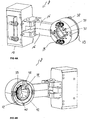
- the nozzles 34 are arranged on the end of pivotally mounted arms 38.
- the lead terminals 36 are provided.
- the pivoting of the arms 38 takes place with the aid of an actuator 40, wherein for each partial arm 16, a separate actuator 40 is provided, which, however, are synchronized with each other.
- the adjusting movement is transmitted from the actuator 40 via a drive axle and a kind of gear transmission to the individual arms 38 for the exercise of the pivoting movement.
- a single fixing unit 28 is provided with only one pivotable arm 38, the arm 38 is in this case formed in the manner of a pan or articulated lever.
- a ring member 39 is provided in the embodiment, which is adjustable in the axial direction and thereby acts on the articulated lever to bring about the desired adjustment.
- the arm 38 is arranged rotatable about the central space 22 around. In the exemplary embodiment, this is made possible by an inner rotor 42 and a drive sprocket 44.
- a rotation of the inner rotor 42 attached to the arm 38 is made possible around the central space 22 around. Due to the Partial arms 16, both the inner rotor 42 and the drive sprocket 44 is formed in two parts.
- module units are arranged approximately in a star shape on the tool head.
- the module units are each attached to a star-shaped support plate by screws.
- Each of the modular units has as a component a fixing unit 28 with a nozzle 34.
- the modular units are, in particular, piezoelectric units, ie the nozzles 34 are designed as piezoelectric nozzles, ie the fixing agent is ejected from the nozzles 34 in a manner known per se with the aid of the piezoelectric effect.
- the curing unit 30, which is formed in this exemplary embodiment by UV light sources 46, is additionally integrated into the respective module unit. These are arranged opposite to the machining direction 20 following the nozzles 34.
Description
Die Erfindung betrifft eine Bearbeitungsstation sowie ein Verfahren zur automatisierten Fertigung von aus einer Mehrzahl von Einzelleitungen bestehenden Kabelsätzen mit den Oberbegriffen des Anspruchs 1 beziehungsweise des Anspruchs 14. Die Erfindung betrifft weiterhin eine Bearbeitungseinheit für eine derartige Bearbeitungsstation.The invention relates to a processing station and to a method for the automated production of cable sets consisting of a plurality of individual lines with the preambles of claim 1 and of
Eine derartige Vorrichtung und ein derartiges Verfahren sind aus der
Unter Kabelsatz wird allgemein ein vorkonfektioniertes Leitungsbündel verstanden, bei dem eine Mehrzahl von Einzelleitungen entsprechend einem vordefinierten Verlauf oder Layout und in definierter Länge miteinander verbunden sind. Kabelsätze weisen üblicherweise eine verzweigte Struktur auf mit einer Mehrzahl von Verästelungen oder Abzweigungen. Die Einzelleitungen weisen eine begrenzte Länge auf, bei dem Kabelsatz handelt es sich daher insgesamt um ein vorgefertigtes, vorkonfektioniertes Stückgut. An den einzelnen Enden der Einzelleitungen sind oftmals bereits Kontaktelemente wie Stecker oder dergleichen angeschlagen. Derartige Kabelsätze werden insbesondere auch in der Automobilindustrie, beispielsweise zur elektrischen Verbindung einer Mehrzahl von Verbrauchern mit einer zentralen Verteiler- oder Steuereinheit eingesetzt.Under cable set is generally understood a prefabricated trunk group, in which a plurality of individual lines according to a predefined course or layout and are connected to each other in a defined length. Cordsets usually have a branched structure with a plurality of branches or branches. The individual cables have a limited length, the cable set is therefore a total of a prefabricated, prefabricated cargo. At the individual ends of the individual lines often contact elements such as plugs or the like are posted. Such cable sets are used in particular in the automotive industry, for example for the electrical connection of a plurality of consumers with a central distribution or control unit.
Die Fertigung eines derartigen Kabelsatzes wird heutzutage in weiten Bereichen noch manuell ausgeführt. Hierzu werden zunächst die für den Kabelsatz erforderlichen Einzelleitungen auf einem sogenannten Montage- oder Kabelbrett entsprechend dem definierten und gewünschten Verlauf verlegt. Dabei werden sie von Haltern aufgenommen. Anschließend wird das auf diese Weise aus den Einzelleitungen ausgebildete lose Leitungsbündel fixiert, indem eine Bandierung um die Einzelleitungen angebracht wird. Dies erfolgt manuell beispielsweise mit speziellen selbstklebenden Bändern. Aus der
Für die Bandierung bieten sich unterschiedliche Möglichkeiten an, nämlich eine sogenannte Vollbandierung, bei der das Leitungsbündel vollkommen mit der Bandierung umgeben ist oder auch eine sogenannte Sparbandierung, bei der das Leitungsbündel nur an Teilbereichen von der Bandierung umgeben ist. Zur Vermeidung von Klappergeräuschen im späteren Einsatz werden spezielle Tapes oder Bandierungen, nämlich sogenannte Flauschbänder eingesetzt. Die Bandierung weist daher je nach Einsatzort des Kabelsatzes unterschiedliche Funktionen auf. Die Hauptfunktion besteht in der Verbindung der Einzelleitungen. Daneben dient die Bandierung oftmals auch zur Befestigung von Halterungselementen oder zusätzlichen Elementen. Weiterhin dient die Bandierung als mechanischer Schutz, als Klapperschutz etc. Bei Bedarf wird das Leitungsbündel zumindest in Teilbereichen mit einem geschäumten Körper umgeben, um beispielsweise einen sogenannten formstabilen Kabelsatz auszubilden, bei dem die Abzweigungen und Verästelungen in ihrer Geometrie fixiert sind. Für derartige geschäumte Kabelsätze wird das Leitungsbündel üblicherweise in eine Werkzeugform (Schäumform) eingelegt, in die anschließend ein aufschäumbares Material, beispielsweise ein PU-Material eingebracht wird.For the banding, there are different possibilities, namely a so-called full banding, in which the cable bundle is completely surrounded by the banding or also a so-called savings banding, in which the cable bundle is surrounded only at partial areas of the banding. To avoid rattling noises in later use special tapes or banding, namely so-called loop bands are used. The banding therefore has different functions depending on the location of the cable set. The main function is the connection of the individual cables. In addition, the banding is often used for attachment of support elements or additional elements. Furthermore, the banding serves as a mechanical protection, as rattle protection etc. If necessary, the trunk group is surrounded at least in some areas with a foamed body, for example, to form a so-called dimensionally stable cable set, in which the branches and branches are fixed in their geometry. For such foamed cable sets, the cable bundle is usually inserted into a mold (foam mold) into which a foamable material, such as a PU material is then introduced.
Da es sich bei diesen Kabelsätzen nicht um Meterware, also Endlosware handelt und die Kabelsätze sich zudem durch eine Vielzahl von Verzweigungen und Verästelungen auszeichnen, ist das Anbringen einer solchen Bandierung bis heute nicht automatisiert. Ein Kabelsatz weist typischerweise nämlich nur sehr kurze geradlinige Abschnitte ohne Verästelungen auf, die üblicherweise lediglich im Bereich von bis zu einigen 10 cm liegen.Since these sets of cables are not by the meter, so endless goods and the cable sets are also characterized by a variety of branches and ramifications, the attachment of such a banding is not automated until today. Namely, a cable set typically has only very short rectilinear portions without ramifications, which are usually only in the range of up to several 10 cm.
Ausgehend hiervon liegt der Erfindung die Aufgabe zugrunde, ein automatisiertes Zusammenfügen der Einzelleitungen zur Herstellung eines Kabelsatzes zu ermöglichen.Proceeding from this, the invention has the object to enable automated assembly of the individual cables for the production of a cable set.
Die Aufgabe wird gemäß der Erfindung gelöst durch eine Bearbeitungsstation mit den Merkmalen des Anspruchs 1, durch eine Bearbeitungseinheit mit den Merkmalen des Anspruchs 12 sowie mit einem Verfahren mit den Merkmalen des Anspruchs 14.The object is achieved according to the invention by a processing station having the features of claim 1, by a processing unit having the features of
Die nachfolgend angeführten Vorteile und bevorzugten Ausgestaltungen jeweils wechselseitig sinngemäß auf die Bearbeitungsstation, das Verfahren sowie die Bearbeitungseinheit übertragbar.The following advantages and preferred embodiments mutually mutatis mutandis transferable to the processing station, the method and the processing unit.
Zur automatisierten Fertigung von aus Einzelleitungen bestehenden Kabelsätzen, insbesondere zum Verbinden der Einzelleitungen nach Art einer Bandierung, wird ein aus den Einzelleitungen bestehendes, loses Leitungsbündel, welches einen vorgegebenen und verzweigten Verlauf mit üblicherweise einer Vielzahl von Abzweigungen und Verästelungen aufweist, von einer Trägereinheit gehalten, an dieser also vorfixiert. Unter losem Leitungsbündel wird hierbei die Nebeneinander-Anordnung der Einzelleitungen entsprechend dem vorgesehenen Verlauf ohne Bandierung oder ähnlichem verstanden. Die Einzelleitungen liegen daher lose nebeneinander, werden allenfalls von Halteelementen der Trägereinheit vorfixiert. Im zweiten Schritt werden die Einzelleitungen mit Hilfe einer Bearbeitungseinheit automatisiert aneinander nach Art einer Bandierung fixiert. Hierzu weist die Bearbeitungseinheit eine Fixiereinheit auf, die ein Fixiermittel auf das lose Leitungsbündel aufbringt, so dass die Einzelleitungen durch das Fixiermittel miteinander verbunden sind. Das Fixiermittel ersetzt daher die Bandierung. Zum Aufbringen des Fixiermittels werden die Bearbeitungseinheit und das Leitungsbündel vorzugsweise mit Hilfe eines Manipulators relativ zueinander in einer Bearbeitungsrichtung entlang des Leitungsbündels verfahren.For automated production of cable harnesses consisting of individual cables, in particular for connecting the individual cables in the manner of banding, a loose cable bundle consisting of the individual cables, which has a predetermined and branched course with usually a multiplicity of branches and branchings, is held by a carrier unit, at this prefixed. Under loose cable bundle here is the juxtaposition of the individual lines according to the intended course understood without banding or the like. The individual lines are therefore loosely next to each other, are at best prefixed by holding elements of the carrier unit. In the second step, the individual lines are automatically fixed to one another in the manner of a banding with the aid of a processing unit. For this purpose, the processing unit has a fixing unit, which applies a fixing means to the loose line bundle, so that the individual lines are connected to one another by the fixing means. The fixer therefore replaces the banding. To apply the fixing agent, the processing unit and the wire bundle are preferably moved relative to one another in a processing direction along the wire bundle with the aid of a manipulator.
Die Trägereinheit ist vorzugsweise nach Art eines herkömmlichen Montage- oder Kabelbretts ausgebildet und weist - je nach Größe des Kabelsatzes - eine Fläche von bis zu einigen m2 auf, auf der das Leitungsbündel entsprechend dem vorgesehenen Verlauf, also der vorgesehenen verzweigten und verästelten Geometrie des Kabelsatzes verlegt ist. Bei den Einzelleitungen handelt es sich üblicherweise um isolierte Leiteradern aus einem leitfähigen Material wie beispielsweise Kupfer, Aluminium oder Legierungen hiervon.The carrier unit is preferably designed in the manner of a conventional mounting or cable board and has - depending on the size of the cable set - an area of up to a few m 2 , on the line bundle according to the intended course, ie the intended branched and ramified geometry of the cable set is relocated. The individual lines are usually insulated conductor wires made of a conductive material such as copper, aluminum or alloys thereof.
Die Trägereinheit weist als Halteelemente für das Leitungsbündel vorzugsweise Stangenhalterungen auf, die endseitig beispielsweise eine gabel- oder halbringförmige Aufnahme ausbilden, in die das Leitungsbündel eingelegt wird. Das Leitungsbündel wird daher beabstandet von einer Ebene gehalten, beispielsweise ein plattenartiger Träger, so dass es vollumfänglich von der Bearbeitungseinheit umgriffen werden kann.As a holding element for the cable bundle, the carrier unit preferably has rod holders which, for example, form a forked or semi-annular receptacle at the end, into which the cable bundle is inserted. The cable bundle is therefore kept at a distance from a plane, for example a plate-like carrier, so that it can be fully encompassed by the processing unit.
Durch den Ersatz der bisher üblichen Bandierung mittels Bändern durch das Aufbringen des Fixiermittels beispielsweise mit Hilfe eines Sprüh- oder Spritzverfahrens ist ein automatisiertes Fixieren der Einzelleitungen aneinander nach Art einer Bandierung in wirtschaftlicher und zugleich prozesssicherer Weise ermöglicht, so dass insgesamt ein hoher Automatisierungsgrad bei der Kabelsatzfertigung erreicht ist. Eine aufwändige manuelle Bandierung der Einzelleitungen aneinander entfällt damit. Es sind mit dieser Ausgestaltung durch eine geeignete Ansteuerung sowohl Vollbandierungen als auch sogenannte Spot- oder Sparbandierungen ermöglicht.By replacing the usual banding by means of bands by the application of the fixing agent, for example by means of a spraying or spraying an automated fixing of the individual lines to each other in the manner of banding in an economical and at the same process-reliable manner allows, so that a total of a high degree of automation in the cable harness is reached. A complex manual banding of the individual lines to each other is thus eliminated. With this configuration, both full banding and so-called spot or savings bandings are made possible by a suitable control.
Der Manipulator ist beispielsweise ein Aktuator, welcher die Bearbeitungseinheit in xyz-Richtung verfahren kann und insbesondere ergänzend auch eine Rotation um die durch die Bearbeitungsrichtung definierte Achse erlaubt. Vorzugsweise handelt es sich bei dem Manipulator um einen Roboterarm eines mehrachsigen Industrieroboters, beispielsweise eines sogenannten 6-achsigen Industrieroboters. Mit diesem ist eine Vielzahl von Freiheitsgraden ermöglicht. Dadurch ist eine hohe Designfreiheit und hohe Flexibilität erreicht, was insbesondere bei den unterschiedlichen Anforderungen und Ausgestaltungen bzw. Typen an Kabelsätzen von besonderem Vorteil ist.The manipulator is, for example, an actuator, which can move the processing unit in the xyz direction and, in particular, additionally allows rotation about the axis defined by the machining direction. Preferably, the manipulator is a robot arm of a multi-axis industrial robot, for example a so-called 6-axis industrial robot. With this a variety of degrees of freedom is possible. As a result, a high degree of design freedom and high flexibility is achieved, which is particularly advantageous for the different requirements and designs or types of cable sets.
Für die Ausübung der Relativbewegung zwischen Bearbeitungseinheit und dem Leitungsbündel wird vorzugsweise die Bearbeitungseinheit von einer Roboterhand eines mehrachsigen Industrieroboters geführt. Alternativ besteht auch die Möglichkeit, die gesamte Trägereinheit zu führen und die Bearbeitungseinheit ortsfest zu belassen.For carrying out the relative movement between the processing unit and the line bundle, the processing unit is preferably guided by a robot hand of a multi-axis industrial robot. Alternatively, there is also the possibility to guide the entire carrier unit and to leave the processing unit stationary.
Das Fixiermittel weist beim Auftragen eine flüssige oder zähflüssige Konsistenz auf und härtet nach dem Aufbringen auf das Leitungsbündel aus. Hierdurch ist ein prozesssicheres Aufbringen des Fixiermittels ermöglicht. Nach dem Aushärten umgibt das Fixiermittel das Leitungsbündel vorzugsweise nach Art eines Bandes oder eines Mantels und hält auf diese Weise die Einzelleitungen zusammen.The fixing agent has a liquid or viscous consistency during application and cures after application to the wire bundle. As a result, a reliable application of the fixing is possible. After curing, the fixing agent surrounds the cable bundle preferably in the manner of a band or a jacket and holds in this way the individual lines together.
Als Fixiermittel wird dabei ein aushärtbares Kunststoff-Harz herangezogen. Hierbei kann es sich auch um ein Zwei-Komponenten-System handeln. Aushärtbare Harzsysteme sind in weiten Bereichen bekannt. Vorzugsweise wird ein geeignetes Harzsystem gewählt, welches zum einen ein prozesssicheres Verarbeiten ermöglicht und welches zum anderen nach dem Aufbringen möglichst schnell, vorzugsweise unmittelbar aushärtet, um möglichst hohe Prozessgeschwindigkeiten zu ermöglichen. Insbesondere ist eine Verfahrgeschwindigkeit der Bearbeitungseinheit relativ zum Leitungsbündel von 100mm pro Sekunde vorgesehen, d.h. das Harzsystem muss eine ausreichend schnelle Aushärtung erlauben. Vorzugsweise ist der Aushärtvorgang zumindest zu einem Großteil beendet, sobald die Bearbeitungseinheit die jeweilige Stelle des Leitungsbündels vollständig überfahren hat. Die Aushärtung des Harzes erfolgt daher quasi instantan unmittelbar nach dem Auftragen auf das Leitungsbündel.The fixing agent used is a hardenable plastic resin. This can also be a two-component system. Curable resin systems are widely known. Preferably, a suitable resin system is selected which, on the one hand, enables process-reliable processing and which, on the other hand, cures as quickly as possible, preferably immediately after application, in order to allow the highest possible process speeds. In particular, a traveling speed of the processing unit relative to the wire bundle of 100 mm per second is provided, i. the resin system must allow a sufficiently fast cure. Preferably, the curing process is completed at least to a large extent as soon as the processing unit has completely crossed over the respective location of the cable bundle. The curing of the resin therefore takes place virtually instantaneously immediately after application to the cable bundle.
Gemäß einer besonders vorteilhaften Ausgestaltung ist die Bearbeitungseinheit zum zumindest teilweisen Umgreifen des Leitungsbündels ausgebildet, so dass die Bearbeitungseinheit beim Bearbeitungsverfahren in radialer Richtung an das Leitungsbündel herangefahren werden kann. Die Bearbeitungseinheit weist hierzu vorzugsweise zumindest zwei zueinander verfahrbare Teilarme auf, die im geschlossenen Zustand die Einzelleitungen vorzugsweise vollständig nach Art eines Ringes umgreifen. Die beiden Teilarme sind vorzugsweise zueinander mit Hilfe eines Stellelements, beispielsweise eines Linearantriebs verschiebbar oder auch über eine Gelenkverbindung miteinander verbunden. Die beiden Teilarme sind bevorzugt über einen nach Art eines Bajonettverschlusses ausgebildeten Verschluss miteinander arretierbar.According to a particularly advantageous embodiment, the processing unit is designed for at least partially encompassing the line bundle, so that the processing unit can be approached in the radial direction to the line bundle during the machining process. For this purpose, the processing unit preferably has at least two mutually movable partial arms which, in the closed state, embrace the individual lines preferably completely in the manner of a ring. The two partial arms are preferably displaceable relative to one another by means of an adjusting element, for example a linear drive, or also connected to one another via a hinge connection. The two arms are preferably lockable with each other via a closure designed in the manner of a bayonet closure.
Alternativ oder ergänzend zu der zweiteiligen Ausgestaltung ist die Bearbeitungseinheit C- oder U-förmig ausgebildet, so dass über den offenen Bereich das Leitungsbündel in den durch die Bearbeitungseinheit definierten Zentralraum eingeführt werden kann.Alternatively or in addition to the two-part embodiment, the processing unit C- or U-shaped, so that over the open area, the trunk group can be inserted into the central space defined by the processing unit.
Diese Ausgestaltung erlaubt ein effizientes, prozesssicheres Aufbringen des Fixiermittels auch bei den komplexen Kabelsatz-Geometrien mit mehreren Verzweigungen. Insbesondere können dadurch auch Hindernisse, wie sie beispielsweise durch die Stabhalterungen gebildet sind, berücksichtigt werden, indem entweder die Öffnung der gabelförmigen Bearbeitungseinheit in eine entsprechende Orientierungslage gebracht wird, bzw. indem die beiden Teilarme etwas geöffnet werden.This embodiment allows an efficient, reliable application of the fixing agent even with the complex cable harness geometries with multiple branches. In particular, this also obstacles, such as those formed by the rod holders, are taken into account by either the opening of the fork-shaped processing unit is brought into a corresponding orientation position, or by the two arms are slightly opened.
In bevorzugter Ausgestaltung ist hierbei vorgesehen, dass die beiden Teilarme symmetrisch bezüglich einer Trennebene ausgebildet sind und die gleichen Bauteile aufweisen. Insbesondere ist dabei vorgesehen, dass jeder der Teilarme die gleichen Bauteile aufweist, insbesondere ein oder mehrerer Fixiereinheiten und / oder Komprimiereinheiten und / oder Aushärteeinheiten.In a preferred embodiment, it is provided that the two partial arms are formed symmetrically with respect to a parting plane and have the same components. In particular, it is provided that each of the partial arms has the same components, in particular one or more fixing units and / or compression units and / or curing units.
Gemäß einer bevorzugten Ausgestaltung ist ergänzend die Verwendung von mehreren unterschiedlichen Fixiermitteln vorgesehen, so dass - je nach Anforderung - entweder bei einem Leitungsbündel oder bei verschiedenen Leitungsbündeln unterschiedliche Fixiermittel eingesetzt werden können, ohne dass ein Werkzeugwechsel erforderlich ist. Die einzelnen Düsen sowie eventuelle Aushärteeinheiten werden hierbei vorzugsweise auf das jeweilige Harzsystem angepasst. Bei dieser Ausführungsvariante umfasst die Bearbeitungsstation daher mehrere Vorratsbehälter für die unterschiedlichen Fixiermittel (unterschiedliche Harzsysteme).According to a preferred embodiment, the use of several different fixing means is provided in addition, so that - depending on the requirements - either with a cable bundle or with different cable bundles different fixatives can be used without a tool change is required. The individual nozzles and any curing units are preferably adapted to the respective resin system. In this embodiment variant, the processing station therefore comprises a plurality of storage containers for the different fixing means (different resin systems).
Vorzugsweise ist allgemein eine Strukturierung des aufgebrachten Fixiermittels durch Aufbringen von Beflockungsmaterial wie beispielsweise Fasern oder andere Festpartikel vorgesehen. Hierdurch werden die gewünschten Eigenschaften beispielsweise zum Scheuerschutz oder Schallschutz geeignet eingestellt. Hierdurch können auch sogenannte "Flauschspender" nachgebildet werden.Preferably, a structuring of the applied fixing agent by applying flocking material such as fibers or other solid particles is generally provided. As a result, the desired properties are set, for example suitable for scuff protection or sound insulation. As a result, so-called "loop dispensers" can be modeled.
Bei einem gewünschten dicken Materialauftrag werden vorzugsweise mehrere Schichten aufgetragen, wobei hier insbesondere auch ein abwechselndes Aufbringen von Fixiermittel und Fasermaterial (Beflockungsmittel) vorgesehen ist.In the case of a desired thick application of material, it is preferable to apply a plurality of layers, in which case in particular an alternating application of fixing agent and fiber material (flocking agent) is also provided.
In bevorzugter Weiterbildung werden mit Hilfe des Fixiermittels zugleich auch weitere Bauteile, wie Klipse oder sonstige Befestigungselemente am Leitungsbündel befestigt, entweder an den Einzelleitungen oder auch an bereits angeschlagenen Steckverbindern. Diese Bauteile werden hierbei an der gewünschten Anbaulage vorfixiert und mit Hilfe des Fixiermittels zuverlässig befestigt.In a preferred development, at the same time other components, such as clips or other fasteners are attached to the cable bundle, either to the individual lines or to already posted connectors with the help of the fixing. These components are in this case prefixed to the desired mounting position and secured reliably by means of the fixing.
In zweckdienlicher Ausgestaltung werden Harz- oder Lacksysteme verendet, die nach dem Aushärten eine ausreichende Steifigkeit und Härte besitzen, um beispielsweise das gesamte Leitungsbündel zumindest in Bereichen formstabil auszuführen.In an expedient embodiment resin or paint systems are used, which have sufficient rigidity and hardness after curing, for example, perform the entire trunk group, at least in areas dimensionally stable.
Auch besteht die Möglichkeit, direkt aus dem aufgebrachten Fixiermittel Bauteile wie Klipse oder Einsteckpins (zum Einstecken in Bohrlöchern in einem Blechbauteil zu befestigen) auszubilden.It is also possible, directly from the applied fixative components such as clips or Einsteckpins (to be plugged into boreholes in a sheet metal component to form).
Zum dosierten Aufbringen des Fixiermittels ist zweckdienlicherweise zumindest eine Düse oder Dosiernadel als Fixiereinheit oder als Teil der Fixiereinheit vorgesehen. In zweckdienlicher Weiterbildung sind insbesondere mehrere Düsen vorgesehen, die in Umfangsrichtung verteilt angeordnet sind, also auf einem Kreis oder einem Kreisbogen liegend. Vorzugsweise umschließen die Düsen dabei im Betrieb das Leitungsbündel zumindest weitgehend ringförmig. Durch diese Ausgestaltung ist ein vollständiges um den Umfang verlaufendes Aufbringen des Fixiermittels nach Art einer Bandierung ermöglicht. Alternativ oder auch ergänzend zu der Ausgestaltung mit mehreren Düsen, die fix angeordnet sind ist eine drehbewegliche Lagerung der zumindest einen Düse vorgesehen.For metered application of the fixing agent, at least one nozzle or metering needle is expediently provided as a fixing unit or as part of the fixing unit. In an expedient development, in particular a plurality of nozzles are provided, which are arranged distributed in the circumferential direction, that is lying on a circle or a circular arc. During operation, the nozzles preferably enclose the cable bundle at least substantially annularly. By this configuration, a complete running around the circumference application of the fixing agent in the manner of a banding is possible. Alternatively or in addition to the embodiment with a plurality of nozzles, which are arranged fixed, a rotatable mounting of the at least one nozzle is provided.
Bei den Düsen handelt es sich vorzugsweise um ansteuerbare Düsen, die über Steuersignale, die von einer Steuereinheit vorgegeben werden, geöffnet und geschlossen werden. Dies erlaubt ein sehr flexibles Aufbringen des Fixiermittels mit unterschiedlichen Auftragsraten und erlaubt insbesondere das Aufbringen des Fixiermittels nach Art unterschiedlicher Bandierungsarten, beispielsweise eine Vollbandierung oder auch eine Sparbandierung, bei der das Fixiermittel schraubenlinienförmig auf das Leitungsbündel aufgetragen wird. Dies wird beispielsweise durch eine sukzessive Ansteuerung der verteilt angeordneten Düsen erreicht. Alternativ oder ergänzend wird dies durch eine Drehbewegung der zumindest einen Düse erzielt.The nozzles are preferably controllable nozzles, which are opened and closed via control signals which are predetermined by a control unit. This allows a very flexible application of the fixing agent with different application rates and in particular allows the application of the fixing agent on the type of different types of tape, for example, a full banding or a savings banding, in which the fixing agent is applied helically to the cable bundle. This is achieved for example by a successive activation of the distributed nozzles. Alternatively or additionally, this is achieved by a rotational movement of the at least one nozzle.
Durch die sukzessive Ansteuerung bzw. durch eine Rotation der zumindest einen Düsen um das Leitungsbündel werden je nach Anforderung in bevorzugter Ausgestaltung strukturierte Muster des Fixiermittels aufgebracht. Anstelle einer vollständigen Drehbewegung ist eine Oszillation über einen beschränkten Winkelbereich von beispielsweise bis zu 120° oder bis zu 180° vorgesehen. Dadurch wird beispielsweise eine netzartige Struktur als Bandierung ausgebildet. Je nach Oszillationsfrequenz und Vorschubgeschwindigkeit kann hier eine sehr engmaschige (bis hin zur vollständigen Bedeckung der Oberfläche) oder auch eine sehr weitmaschige Struktur ausgebildet werden. Die Oszillation / Rotation der Düsen wird alternativ nach Art einer Quasi-Rotation auch durch die sukzessive Ansteuerung von feststehenden Düsen erreicht.As a result of the successive activation or rotation of the at least one nozzle around the cable bundle, structured patterns of the fixing agent are applied as required in a preferred embodiment. Instead of a complete rotary motion, an oscillation over a limited angular range of, for example, up to 120 ° or up to 180 ° is provided. As a result, for example, a net-like structure is formed as banding. Depending on the oscillation frequency and feed rate, a very close-meshed (up to the complete coverage of the surface) or even a very wide-meshed structure can be formed here. The oscillation / rotation of the nozzles is alternatively achieved in the manner of a quasi-rotation by the successive control of fixed nozzles.
Insgesamt ist vorzugsweise eine Mehrzahl von Düsen vorgesehen, die nach Art eines Arrays, beispielsweise ringförmig oder halbringförmig angeordnet sind. Für großflächige Auftragungen sind die Düsen vorzugsweise als Schlitzdüsen ausgebildet.Overall, a plurality of nozzles is preferably provided, which are arranged in the manner of an array, for example annular or semi-annular. For large-area applications, the nozzles are preferably designed as slot nozzles.
Die Düsen sind gemäß einer bevorzugten Variante als Piezodüsen oder Piezodosierer ausgebildet, das Ausstoßen des Fixiermittels erfolgt daher mit Hilfe des piezoelektrischen Effektes.The nozzles are designed according to a preferred variant as piezoelectric nozzles or piezoelectric doser, the ejection of the fixing agent is therefore carried out with the aid of the piezoelectric effect.
In zweckdienlicher Weiterbildung ist vorgesehen, dass mit Hilfe des Manipulators die Bearbeitungseinheit als Ganzes in Umfangsrichtung um das Leitungsbündel herum zur Ausübung der Rotation verfahren wird.In an expedient development it is provided that with the help of the manipulator, the processing unit as a whole is moved in the circumferential direction around the wire bundle around for the exercise of the rotation.
Kabelsätze zeichnen sich allgemein durch eine sehr hohe Vielfalt und hohe Variabilität hinsichtlich ihrer Komplexität und Größe aus. Um bei einer Bearbeitungseinheit eine Vielzahl von unterschiedlichen Kabelsatztypen bearbeiten zu können, ist eine gesteuerte radiale Zustellung der Düsen in Richtung zu einer zentralen Achse hin vorgesehen. Durch diese Maßnahme kann daher die Düse immer in einem optimalen Abstand zum Leitungsbündel gebracht werden. Vorzugsweise ist die Düse dabei an einem Kipphebel gelagert, so dass die Zustellbewegung in radialer Richtung mit Hilfe einer Schwenkbewegung erfolgt. Bei der Anordnung von mehreren Düsen sind vorzugsweise mehrere der Düsen über einen gemeinsamen Antrieb miteinander gekoppelt, so dass eine synchrone Bewegung der Düsen erfolgt.Cable sets are generally characterized by a very high diversity and high variability in terms of their complexity and size. In order to be able to process a multiplicity of different cable types in a processing unit, a controlled radial delivery of the nozzles is provided in the direction towards a central axis. By this measure, therefore, the nozzle can always be brought in an optimal distance to the wire bundle. Preferably, the nozzle is mounted on a rocker arm, so that the feed movement takes place in the radial direction by means of a pivoting movement. In the arrangement of a plurality of nozzles preferably more of the nozzles are coupled together via a common drive, so that a synchronous movement of the nozzles takes place.
Im Hinblick auf eine möglichst schnelle Aushärtung ist an der Bearbeitungseinheit eine Aushärteeinheit angebracht. Die Bearbeitungseinheit ist daher insgesamt multifunktional ausgebildet und weist neben der Funktion des Aufbringens des Fixiermittels auch die Funktion des Aushärtens auf. Je nach Wahl des Härtsystems können hierbei unterschiedliche Aushärteinheiten vorgesehen sein. Bei UVhärtenden Harzsystemen ist beispielsweise eine Lichtquelle, insbesondere UV-Lichtquelle vorgesehen, die das aufgebrachte Fixiermittel bestrahlt. Vorzugsweise ist dabei jeder einzelnen Düse eine eigene Aushärteeinheit bzw. ein eigenes Aushärtelement wie beispielsweise eine Lichtquelle zugeordnet.With a view to curing as quickly as possible, a curing unit is attached to the processing unit. The processing unit is therefore designed to be multifunctional overall and, in addition to the function of applying the fixing agent, also has the function of hardening. Depending on the choice of the curing system different curing units can be provided here. In the case of UV-curing resin systems, for example, a light source, in particular a UV light source, is provided, which irradiates the applied fixing agent. Preferably, each individual nozzle is assigned its own curing unit or its own curing element, such as a light source.
Alternativ zu der UV-Lichtquelle wird zweckdienlicherweise eine Wärmequelle angeordnet, beispielsweise eine Infrarot-Strahlungsquelle. In einer bevorzugten Variante ist für ein Luft-härtendes System die Aushärteeinheit als eine Gasströmungseinheit ausgebildet, über die ein Gas mit Überdruck in Richtung des aufgebrachten Fixiermittels geleitet wird. Hierzu sind zweckdienlicherweise Gasdüsen vorgesehen. Alternativ zu gerichteten, in etwa punktförmigen Düsen ist in einer alternativen Ausgestaltung eine großflächige Strömungsöffnung vorgesehen, die sich zumindest über einen Teilbereich des Umfangs entlang einer Kreisbogenlinie erstreckt. Insbesondere ist dabei zur Ausbildung eines ringförmigen Strömungsmantels eine Ringdüse vorgesehen. Im Falle einer solchen Gasströmungs-Einheit ist daher auch insbesondere ein Lüfter zur Erzeugung des Gasstroms oder / und eine druckbehaftete Gasquelle vorgesehen. Alternativ erfolgt der Anschluss an ein Gasversorgungssystem.As an alternative to the UV light source, a heat source is expediently arranged, for example an infrared radiation source. In a preferred variant, for an air-curing system, the curing unit is a gas flow unit is formed, via which a gas is passed with overpressure in the direction of the applied fixing agent. For this purpose, gas nozzles are expediently provided. As an alternative to directed, approximately punctiform nozzles, in an alternative embodiment, a large-area flow opening is provided which extends along at least a portion of the circumference along a circular arc line. In particular, an annular nozzle is provided to form an annular flow jacket. In the case of such a gas flow unit, a fan for generating the gas flow and / or a pressurized gas source is therefore also provided in particular. Alternatively, it is connected to a gas supply system.
In besonders bevorzugter Ausgestaltung ist hierbei vorgesehen, dass zwischen zwei unterschiedlichen Gasarten umgeschaltet werden kann. Vorzugsweise sind zumindest zwei unterschiedliche Gasversorgungen bereitgestellt, zwischen denen mit einer geeigneten Steuerung, beispielsweise mit Hilfe eines Umschaltventils, umgeschaltet wird. Einige Harzsysteme zeigen ein unterschiedliches Aushärteverhalten in Abhängigkeit des gewählten Gases, was auf diese Weise sinnvoll ausgenutzt wird. So sind beispielsweise Harzsysteme bekannt, die beim Beströmen mit sauerstoffhaltigem Gas (Luft) an ihrer Oberfläche klebrig bleiben, jedoch unter Inertgas, beispielsweise Stickstoff, eine klebefreie Oberfläche ausbilden. Dies wird beispielsweise ausgenutzt, falls die Oberfläche des Fixiermittels mit Fasern / Partikeln nach Art einer Beflockung versehen werden soll.In a particularly preferred embodiment, it is provided that it is possible to switch between two different types of gas. Preferably, at least two different gas supplies are provided, between which with a suitable control, for example by means of a change-over valve, is switched. Some resin systems show a different curing behavior depending on the selected gas, which is meaningfully exploited in this way. Thus, for example, resin systems are known which remain sticky when flowing with oxygen-containing gas (air) on their surface, but form under inert gas, for example nitrogen, a tack-free surface. This is utilized, for example, if the surface of the fixing agent is to be provided with fibers / particles in the manner of a flocking.
Zweckdienlicherweise wird das Gas mit einem ausreichenden Überdruck, beispielsweise von einigen bar, gegen das Fixiermittel gepresst, so dass dieses auch ein Stück weit in das Innere des Leitungsbündels eindringt, so dass eine intensivere Verbindung der Einzelleitungen erzielt wird.Conveniently, the gas is pressed with a sufficient overpressure, for example of a few bar, against the fixing agent, so that this also penetrates a little way into the interior of the line bundle, so that a more intensive connection of the individual lines is achieved.
Die Gaszuströmung wird zweckdienlicherweise alternativ oder ergänzend auch zur Strukturierung des Fixiermittels herangezogen, d.h. das aufgebrachte Fixiermittel wird nach dem Aufbringen durch die Gasströmung in gewisser Weise versetzt, so dass sich beispielsweise Bereiche mit unterschiedlicher Materialstärke ausbilden. Insbesondere lässt sich dadurch eine oszillierende, wellenartige Oberflächenstruktur des Fixiermittels ausbilden. Hierdurch kann beispielsweise in gewisser Weise eine Wellrohr-Eigenschaft herbeigeführt werden mit radial abstehenden Rippen.The gas inflow is expediently used alternatively or additionally also for structuring the fixing agent, ie the applied fixing agent is displaced in a certain way after application by the gas flow, so that, for example, regions with different material thickness are formed. In particular, this allows an oscillating, wave-like surface structure form the fixing agent. In this way, for example, a corrugated tube property can be brought about in some way with radially projecting ribs.
Diese Strukturierung mit variabler Materialdicke des Fixiermittels kann allgemein auch ohne die Gaszuführungseinheit erfolgen.This structuring with variable material thickness of the fixing agent can generally also be carried out without the gas supply unit.
Zu Strukturierungszwecken ist in einer Ausführungsvariante eine separate, zusätzliche Gaszuführungseinheit mit entsprechender Düsenanordnung zu der Aushärteeinheit vorgesehen, die der Aushärteeinheit vorgeschaltet ist.For structuring purposes, in a variant embodiment, a separate, additional gas supply unit with a corresponding nozzle arrangement to the curing unit is provided, which is connected upstream of the curing unit.
Gemäß einer bevorzugten Weiterbildung ist eine Komprimierungseinheit vorgesehen, mit deren Hilfe die Einzelleitungen vor dem Aufbringen des Fixiermittels komprimiert und zu einem Bündel mit definiertem Durchmesser zusammengepresst werden.According to a preferred refinement, a compression unit is provided, with the aid of which the individual lines are compressed prior to the application of the fixing agent and compressed to form a bundle with a defined diameter.
Die Komprimierungseinheit ist dabei derart ausgebildet, dass die Einzelleitungen in radialer Richtung zusammengedrückt werden, vorzugsweise zumindest im Wesentlichen konzentrisch um eine Mitten- oder Zentralachse. Die Komprimierungseinheit weist dabei vorzugsweise einzelne Komprimierelemente auf, die um den Umfang verteilt angeordnet sind. Die einzelnen Komprimierelemente sind beispielsweise als Kreisbogen- oder Ringsegmente ausgebildet, die in radialer Richtung beispielsweise mit Hilfe eines Stempels verfahrbar sind. Gemäß einer bevorzugten Ausgestaltung werden die Komprimierelemente mit Hilfe einer Schwenkbewegung in radialer Richtung versetzt. Sie sind daher randseitig an der Bearbeitungseinheit schwenkbar gelagert. Der Antrieb erfolgt über eine geeignete, ansteuerbare Antriebseinheit. Zweckdienlicherweise sind die Komprimierelemente als einfache Stangen ausgebildet. Die Bewegungen der einzelnen Komprimierelemente sind aufeinander abgestimmt, um eine konzentrische Kompression zu erreichen.The compression unit is designed such that the individual lines are compressed in the radial direction, preferably at least substantially concentrically about a central or central axis. The compression unit preferably has individual compression elements which are distributed around the circumference. The individual compression elements are designed, for example, as circular arc segments or ring segments which can be moved in the radial direction, for example with the aid of a punch. According to a preferred embodiment, the compression elements are offset by means of a pivoting movement in the radial direction. They are therefore pivotally mounted at the edge of the processing unit. The drive takes place via a suitable, controllable drive unit. Conveniently, the compression elements are designed as simple rods. The movements of the individual compression elements are coordinated to achieve concentric compression.
Die Komprimierungseinheit ist dabei zweckdienlicherweise Teil der Bearbeitungseinheit. Diese weist insbesondere die Einheiten Fixiereinheit sowie Komprimierungseinheit auf. Bei Bedarf und in zweckdienlicher Weiterbildung ist auch die dritte Funktionseinheit, nämlich die Aushärteeinheit, in der Bearbeitungseinheit integriert.The compression unit is expediently part of the processing unit. This has in particular the units fixing unit and compression unit. If necessary and in appropriate training is also the third Functional unit, namely the curing unit, integrated in the processing unit.
Insgesamt ist die Bearbeitungseinheit nach Art eines einheitlichen Werkzeugkopfes ausgebildet, welcher entlang des Leitungsbündels verfahren wird. Mit nur einem Überstreichen des Leitungsbündels mit Hilfe dieser Bearbeitungseinheit werden daher zunächst die Einzelleitungen komprimiert, anschließend wird das Fixiermittels aufgebracht und danach erfolgt das Aushärten. Die einzelnen Funktionseinheiten folgen dabei unmittelbar aufeinander. Allgemein weist die Bearbeitungseinheit einen Träger auf, an dem - in Bearbeitungsrichtung betrachtet - eingangsseitig die Komprimierungseinheit, anschließend daran die Fixiereinheit und schließlich die Aushärteeinheit angeordnet ist. Dadurch ist insgesamt eine sehr kompakte Ausgestaltung erreicht und es sind auch hohe Prozessgeschwindigkeiten ermöglicht. Diese kompakte Bauweise erlaubt ein einfaches Handling auch bei komplexen Kabelsatz-Geometrien. Durch die kompakte Ausgestaltung kann die Bearbeitungseinheit, also die einzelnen Funktionseinheiten sehr nah an das Leitungsbündel auch im Bereich von Abzweigungen herangeführt werden.Overall, the processing unit is designed in the manner of a uniform tool head, which is moved along the line bundle. With only one sweep of the wire bundle using this processing unit, therefore, the individual lines are first compressed, then the fixing agent is applied and then the curing takes place. The individual functional units follow each other directly. In general, the processing unit has a carrier on which - viewed in the machining direction - the compression unit is arranged on the input side, then the fixing unit and finally the curing unit are arranged on the input side. As a result, a very compact design is achieved overall and high process speeds are also possible. This compact design allows easy handling even with complex cable harness geometries. Due to the compact design, the processing unit, ie the individual functional units can be brought very close to the trunk group in the range of branches.
Zusammenfassend zeichnet sich die Bearbeitungseinheit, die Bearbeitungsstation sowie das Verfahren in Kombination durch folgende Funktionen / Funktionseinheiten aus, die insbesondere durch ihr Zusammenwirken ein prozesssicheres, automatisiertes Fixieren der Einzelleitungen eines Leitungsbündels eines Kabelsatzes nach Art einer Bandierung ermöglichen:
- Bündeln / Komprimieren der Einzelleitungen mit Hilfe der Komprimierungseinheit und Zusammenhalten der Einzelleitung bis zum Auftragen des Fixiermittels (die Komprimierungseinheit ist der Fixiereinheit unmittelbar (< 5 cm) vorgeschaltet,
- Auftragen des Fixiermittels mit Hilfe der Fixiereinheit, wobei das Fixiermittel ein insbesondere UV-härtendes Harzsystem ist
- optional eine Strukturierung des noch nicht ausgehärteten Harzes mittels eines Gasstromes mit Hilfe der Gaszuführeinheit
- Aushärten des Harzes mittels der Aushärteeinheit.
- Bundling / compressing the individual cables with the help of the compression unit and holding the single cable together until applying the fixative (the compression unit is connected directly to the fuser unit (<5 cm),
- Applying the fixing agent with the aid of the fixing unit, wherein the fixing agent is a particular UV-curing resin system
- optionally a structuring of the not yet cured resin by means of a gas stream by means of Gaszuführeinheit
- Hardening of the resin by means of the curing unit.
Sämtliche Funktionseinheiten sind dabei innerhalb der nach Art eines Werkzeugkopfes ausgebildeten Bearbeitungseinheit integriert. Diese ist dabei vorzugsweise zum Umgreifen des Leitungsbündels und insbesondere aus zwei Teilarmen ausgebildet.All functional units are integrated within the processing unit designed in the manner of a tool head. This is preferably designed to encompass the cable bundle and in particular of two partial arms.
Ausführungsbeispiele der Erfindung werden im Folgenden anhand der Figuren näher erläutert. Es zeigen jeweils in teilweise schematischen Darstellungen:
- Fig. 1
- eine grob vereinfachte Aufsicht auf eine Bearbeitungsstation zur automatisierten Fertigung eines Kabelsatzes,
- Fig. 2
- eine stark vereinfachte und schematisierte Seitendarstellung einer Bearbeitungseinheit und Trägereinheit,
- Fig. 3A,B
- eine perspektivische Ansicht sowie eine Vorderansicht einer teilweise vereinfacht dargestellten Bearbeitungseinheit gemäß einer ersten Ausführungsvariante,
- Fig. 4A, B
- eine perspektivische Vorderansicht (
Fig. 4A ) sowie Rückansicht (Fig. 4B ) in teilweise vereinfachter Darstellung gemäß einer zweiten Ausführungsvariante und - Fig. 5A, B
- eine perspektivische Vorderansicht (
Fig. 5A ) sowie eine Rückansicht (Fig. 5B ) in teilweise vereinfachter Darstellung einer dritten Ausführungsvariante der Bearbeitungseinheit.
- Fig. 1
- a simplified overview of a processing station for the automated production of a cable set,
- Fig. 2
- a highly simplified and schematic side view of a processing unit and carrier unit,
- Fig. 3A, B
- a perspective view and a front view of a partially simplified processing unit shown according to a first embodiment,
- Fig. 4A, B
- a front perspective view (
Fig. 4A ) and rear view (Fig. 4B ) in a partially simplified representation according to a second embodiment and - Fig. 5A, B
- a front perspective view (
Fig. 5A ) and a rear view (Fig. 5B ) in a partially simplified representation of a third embodiment of the processing unit.
In den Figuren sind gleichwirkende Teile mit den gleichen Bezugszeichen versehen.In the figures, like-acting parts are provided with the same reference numerals.
Das grundsätzliche Verfahren zur automatisierten Fertigung von Kabelsätzen wird zunächst anhand der
Der Manipulator 6 weist mehrere Freiheitsgrade auf, um die Bearbeitungseinheit 8 relativ zu der Trägereinheit 4 an beliebige Positionen verfahren zu können. Insbesondere bietet der Manipulator 6 zumindest einen rotorischen Freiheitsgrad, so dass die Bearbeitungseinheit 8 mit Hilfe des Manipulators 6 insgesamt rotiert werden kann.The
Auf der Trägereinheit 4 ist ein verzweigtes Leitungsbündel 10 auf Halteelementen 12 aufgelegt. Das Leitungsbündel 10 besteht dabei aus einer Mehrzahl von Einzelleitungen 14 (
Wie bereits in
Beim Leitungsbündel 10 sind die Einzelleitungen 14 zunächst nur lose aneinander gehalten. Mit Hilfe der Bearbeitungseinheit 8 wird als Fixiermittel ein aushärtbares Harz in flüssiger oder zähflüssiger Form auf das Leitungsbündel 10 sukzessive in Bearbeitungsrichtung 20 aufgebracht. Am Ende dieser Behandlung sind die Einzelleitungen 14 daher aneinander fixiert. Das Leitungsbündel 10 mit den dann fixierten Einzelleitungen 14 bildet den fertigen Kabelsatz.When
Wie aus
Aufgrund der speziellen Ausgestaltung der Bearbeitungseinheit 8 und dem grundsätzlich neuen Konzept des Aufbringens eines Fixiermittels, welches nach dem Aufbringen aushärtet und die Einzelleitungen 14 nach Art einer Bandierung fixiert, ist nunmehr in wirtschaftlich vertretbarer Weise eine automatisierte Fertigung ermöglicht. Ein besonderer Gesichtspunkt hierbei ist das grundlegende Konzept, dass die Bearbeitungseinheit 8 radial, also senkrecht zur Bearbeitungsrichtung 20 an das Leitungsbündel 10 herangeführt und dieses umgreifen kann. Im Ausführungsbeispiel ist dies durch die verstellbaren Teilarme 16 ermöglicht. Sobald eine Verzweigungsstelle oder ein sonstiges Hindernis, wie beispielsweise ein Halteelement 12 kommt, werden die Teilarme 16 geöffnet, die Bearbeitungseinheit 8 über die Verzweigungsstelle bzw. das Hindernis hinweg gefahren um anschließend mit dem Aufbringen des Fixiermittels mit geschlossenen Teilarmen 16 fortzufahren. Der Manipulator 6 und die Bearbeitungseinheit 8 werden mit Hilfe einer hier nicht näher dargestellten Steuereinheit gesteuert.Due to the special design of the
Alternativ zu der Ausgestaltung mit den beiden Teilarmen 16 besteht auch die Möglichkeit einer U- oder C-förmigen Ausgestaltung der Bearbeitungseinheit 8. In diesem Fall ist es nicht zwingend erforderlich, die Bearbeitungseinheit 8 bei Hindernissen oder Verzweigungen vom Leitungsbündel 10 zurückzuziehen. Vielmehr reicht eine geeignete Rotation der Bearbeitungseinheit 8 mit Hilfe des Manipulators 6 aus. Die einzelnen Zweige des verzweigten Leitungssatzes 10 werden je nach Bedarf nacheinander nach Art einer Bandierung mit dem Fixiermittel versehen.As an alternative to the configuration with the two
Beim Betrieb wird die Bearbeitungseinheit 8 in Bearbeitungsrichtung 20 entlang des Leitungsbündels 10 verfahren. Dabei erfolgt mit der Bearbeitungseinheit 8 zunächst ein Komprimieren der Einzelleitungen 14, das Auftragen des Fixiermittels, ggf. eine Strukturierung des Fixiermittels sowie das Aushärten des Fixiermittels. Die Verfahrgeschwindigkeit beträgt dabei vorzugsweise einige cm / Sekunde bis zu etwa 10cm /Sekunde, zumindest in Bereichen ohne Hindernisse.During operation, the
Ausführungsbeispiele für einen speziellen Aufbau der Bearbeitungseinheit 8 werden nachfolgend anhand der
Bei allen drei Ausführungsvarianten sind zwei linear zueinander verstellbare Teilarme 16 vorgesehen, die jeweils ein holmartiges Tragelement umfassen, an dessen Ende jeweils ein halbringförmiger Bearbeitungskopf angeordnet ist. Die beiden halbringförmigen Bearbeitungsköpfe bilden im geschlossenen Zustand der Teilarme 16 einen geschlossenen Werkzeugkopf aus, der in seinem Inneren den Zentralraum 22 umschließt. Der Begriff halbring- oder ringförmig im Zusammenhang mit dem Werkzeugkopf ist hierbei weit zu verstehen und umfasst auch die Ausführungsvarianten der
In allen drei Ausführungsvarianten sind im Werkzeugkopf zwei Funktionseinheiten integriert, nämlich eine eingangsseitige Komprimierungseinheit 26 sowie eine sich daran anschließende Fixiereinheit 28. Bei der Ausführungsvariante nach
Die Komprimierungseinheit 26 ist bei allen drei Ausführungsvarianten identisch ausgebildet und weist mehrere umfangsseitig zum Zentralraum 22 angeordnete Komprimierungselemente 32 auf. Im Ausführungsbeispiel sind vier Stück vorgesehen. Diese sind dabei gebildet durch an ihrer Endseite drehbar gelagerte Stangen, die motorisch angetrieben in den Zentralraum 22 hinein verschwenkbar sind. Da sich die einzelnen Stangen kreuzen, wird beim Schwenken zum Zentralraum 22 hin das im Zentralraum 22 einliegende Leitungsbündel 10 komprimiert und weiter gebündelt. Zum Verschwenken der Stangen ist ein hier nicht näher dargestellter Antriebsmechanismus vorgesehen, welcher am Ende über eine Verzahnung zwischen zwei benachbarten Komprimierungselementen 32 für eine synchrone Bewegung auf jeweils zwei der Komprimierungselemente 32 übertragen wird, wie dies aus den
Die Fixiereinheiten 28 umfassen jeweils eine Düse 34, über die das Fixiermittel austritt. Das Fixiermittel wird über geeignete Zuführungen den einzelnen Fixiereinheiten 28 zugeführt. In
Im Ausführungsbeispiel der
Beim Ausführungsbeispiel der
Bei der in der
Bei der Ausführungsvariante gemäß der
In die jeweilige Moduleinheit ist ergänzend auch noch die Aushärteeinheit 30 integriert, die in diesem Ausführungsbeispiel gebildet ist durch UV-Lichtquellen 46. Diese sind entgegen der Bearbeitungsrichtung 20 nachfolgend zu den Düsen 34 angeordnet.The curing unit 30, which is formed in this exemplary embodiment by
- 22
- Bearbeitungsstationprocessing station
- 44
- Trägereinheitsupport unit
- 66
- Manipulatormanipulator
- 88th
- Bearbeitungseinheitprocessing unit
- 1010
- Leitungsbündeltrunk group
- 1212
- Halteelementenretaining elements
- 1414
- EinzelleitungenSingle lines
- 1616
- Teilarmepartial arms
- 1818
- Aktuatoractuator
- 2020
- Bearbeitungsrichtungmachining direction
- 2222
- ZentralraumCentral Region
- 2424
- Kontaktelementecontact elements
- 2626
- Komprimierungseinheitcompression unit
- 2828
- Fixiereinheitfuser
- 3030
- Aushärteeinheitcuring unit
- 3232
- Komprimierungselementecompression elements
- 3434
- Düsejet
- 3636
- Leitungsanschlüssecable connections
- 3838
- Armepoor
- 3939
- Ringelementring element
- 4040
- Stellantriebactuator
- 4242
- Innenrotorinner rotor
- 4444
- AntriebszahnkranzDrive sprocket
- 4646
- UV-LichtquellenUV light sources
Claims (14)
- Processing station (2) for the automated production of a cable set consisting of a multitude of single cables (14) having- a carrier unit (4) for holding a cable bundle (10) consisting of the single cables (14) with a predefined, also branched routing,- a processing unit (8) to automatically fix the single cables (14) of the cable bundle (10) to one another,- a manipulator (6) for the relative movement of the processing unit (8) to the cable bundle (10),characterised in that
the processing unit (8) comprises a fixing unit (28) which is formed to automatically apply a fixing agent to the cable bundle (10), wherein a setting resin is provided as the fixing agent. - Processing station (2) according to claim 1 in which the processing unit (8) is formed for enclosing the cable bundle (10), and for this purpose optionally- has at least two arm sections (16) which can be moved towards one another and enclose the single cables (14) in a closed state- is C- or U-shaped.
- Processing station (2) according to one of the preceding claims, in which several different fixing agents are provided.
- Processing station (2) according to one of the preceding claims, in which the processing unit (8) is formed for structuring the applied fixing agent, such as applying a solid material, or for the production of different material thicknesses of the fixing agent in the routing of the cable bundle (10).
- Processing station (2) according to one of the preceding claims, in which the fixing unit (28) has one nozzle (34) or several nozzles (34) distributed around the circumference.
- Processing station (2) according to claim 5, in which at least one nozzle (34) is arranged to be rotatable around the cable bundle (10).
- Processing station (2) according to claim 5 or 6, in which at least one nozzle (34) is able to be moved in the radial direction towards the cable bundle (10).
- Processing station (2) according to one of claims 5 to 7 and claim 2, in which at least one nozzle (34) is arranged on every arm section (16).
- Processing station (2) according to one of the preceding claims, in which the processing unit (8) has a setting unit (30) for setting the applied fixing agent, and the setting unit (30) in particular optionally has a UV light source (46), a gas supply unit, a heat source.
- Processing station (2) according to one of the preceding claims, in which the processing unit (8) has a compressing unit (26) for compressing the single cables (14).
- Processing station (2) according to claim 10, in which the compression unit (26) has several compressing elements (32) distributed on an arc and in particular formed as rotatable rods, with the aid of which the single cables (14) are compressed.
- Processing unit (8) for a processing station (2) according to one of the preceding claims which is formed for the automated fixing of the single cables (14) of the cable bundle (10) to one another and has a fixing unit (28) that is formed for the automated application of a settable resin as a fixing agent on the cable bundle (10).
- Processing unit (8) according to claim 12,- that has the arm section (16) which can be moved towards one another and, in the closed state, circularly enclose a central area (22) that is C- or U-shaped,- in which several nozzles (34) for the application of a settable fixing agent are distributed around the central area (22), or one nozzle (34) is arranged to be movable around the central area (22)- which has a compression unit (26) which comprises several compression elements (32) distributed around the central area (22) which are movable in the radial direction,- which if required has a setting unit (30) for setting the fixing agent.
- Process for the automated production of cable sets consisting of a multitude of single cables (14), in which a cable bundle (10) consisting of the single cables (14) having a predetermined, also branched routing is held in a carrier unit (4), and the single cables (14) of the cable bundle (10) are automatically fixed to one another with the aid of a processing unit (8), wherein the processing unit and the cable bundle (10) can be moved relative to one another in the processing direction (20) along the cable bundle (10),
characterised in that
a fixing agent is applied to the cable bundle (10) via a fixing unit (28), and a settable resin is used as a fixing agent.
Priority Applications (1)
| Application Number | Priority Date | Filing Date | Title |
|---|---|---|---|
| RS20170052A RS55606B1 (en) | 2011-03-04 | 2011-06-29 | Processing station and method for the automated manufacture of cable harnesses and processing unit for such a processing station |
Applications Claiming Priority (2)
| Application Number | Priority Date | Filing Date | Title |
|---|---|---|---|
| DE102011012998 | 2011-03-04 | ||
| PCT/EP2011/003214 WO2012119618A1 (en) | 2011-03-04 | 2011-06-29 | Processing station and method for the automated manufacture of cable harnesses and processing unit for such a processing station |
Publications (2)
| Publication Number | Publication Date |
|---|---|
| EP2681981A1 EP2681981A1 (en) | 2014-01-08 |
| EP2681981B1 true EP2681981B1 (en) | 2016-10-19 |
Family
ID=44509148
Family Applications (1)
| Application Number | Title | Priority Date | Filing Date |
|---|---|---|---|
| EP11741098.5A Not-in-force EP2681981B1 (en) | 2011-03-04 | 2011-06-29 | Processing station and method for the automated manufacture of cable harnesses and processing unit for such a processing station |
Country Status (4)
| Country | Link |
|---|---|
| US (1) | US9787042B2 (en) |
| EP (1) | EP2681981B1 (en) |
| RS (1) | RS55606B1 (en) |
| WO (1) | WO2012119618A1 (en) |
Cited By (1)
| Publication number | Priority date | Publication date | Assignee | Title |
|---|---|---|---|---|
| DE102018218363A1 (en) * | 2018-10-26 | 2020-04-30 | Leoni Bordnetz-Systeme Gmbh | Device and method for applying a curable mass |
Families Citing this family (4)
| Publication number | Priority date | Publication date | Assignee | Title |
|---|---|---|---|---|
| US10116422B2 (en) | 2012-11-02 | 2018-10-30 | Qualcomm Incorporated | Managing cross-carrier scheduling in carrier aggregation with EPDCCH in LTE |
| DE102015214929A1 (en) | 2015-08-05 | 2017-02-09 | Leoni Bordnetz-Systeme Gmbh | Cable set and method for its manufacture |
| JP6169238B1 (en) * | 2016-09-21 | 2017-07-26 | 京セラ株式会社 | Electronic device, program, and control method |
| CN112908565B (en) * | 2021-01-29 | 2022-05-13 | 广东亚泰科技有限公司 | Wire arranging device and wire harness processing equipment |
Citations (1)
| Publication number | Priority date | Publication date | Assignee | Title |
|---|---|---|---|---|
| US5851288A (en) * | 1990-10-29 | 1998-12-22 | Gem Gravure Company, Inc. | Apparatus for marking a continuous substrate |
Family Cites Families (5)
| Publication number | Priority date | Publication date | Assignee | Title |
|---|---|---|---|---|
| US3456338A (en) * | 1966-07-11 | 1969-07-22 | Gen Electric | Method for changing the configuration of and for bonding electrical coils of inductive devices |
| JPS6016711B2 (en) * | 1978-12-11 | 1985-04-26 | 木谷電器株式会社 | Feeding device for electric wires with plug terminals to the plug forming machine |
| DE202007012534U1 (en) * | 2007-09-06 | 2007-11-29 | Selbach, Dirk | Cable harness production |
| DE102008022337A1 (en) * | 2008-04-29 | 2009-11-05 | Newfrey Llc, Newark | Apparatus and method for automated circumferential wrapping of a wiring harness with a fastening system consisting of a fastener and a winding tape |
| US8146491B2 (en) | 2008-04-29 | 2012-04-03 | Newfrey Llc | Apparatus and method for automatically, circumferentially wrapping a cable harness |
-
2011
- 2011-06-29 EP EP11741098.5A patent/EP2681981B1/en not_active Not-in-force
- 2011-06-29 WO PCT/EP2011/003214 patent/WO2012119618A1/en active Application Filing
- 2011-06-29 RS RS20170052A patent/RS55606B1/en unknown
-
2013
- 2013-09-04 US US14/017,863 patent/US9787042B2/en active Active
Patent Citations (1)
| Publication number | Priority date | Publication date | Assignee | Title |
|---|---|---|---|---|
| US5851288A (en) * | 1990-10-29 | 1998-12-22 | Gem Gravure Company, Inc. | Apparatus for marking a continuous substrate |
Cited By (2)
| Publication number | Priority date | Publication date | Assignee | Title |
|---|---|---|---|---|
| DE102018218363A1 (en) * | 2018-10-26 | 2020-04-30 | Leoni Bordnetz-Systeme Gmbh | Device and method for applying a curable mass |
| DE102018218363B4 (en) | 2018-10-26 | 2020-06-04 | Leoni Bordnetz-Systeme Gmbh | Device and method for applying a curable mass |
Also Published As
| Publication number | Publication date |
|---|---|
| WO2012119618A1 (en) | 2012-09-13 |
| EP2681981A1 (en) | 2014-01-08 |
| US20140013596A1 (en) | 2014-01-16 |
| US9787042B2 (en) | 2017-10-10 |
| RS55606B1 (en) | 2017-06-30 |
Similar Documents
| Publication | Publication Date | Title |
|---|---|---|
| EP2681981B1 (en) | Processing station and method for the automated manufacture of cable harnesses and processing unit for such a processing station | |
| EP1713153B1 (en) | Line-coupling | |
| EP1761982B1 (en) | Device comprising two parts relatively movable with respect to each other as well as guide chain assembly | |
| EP3503127B1 (en) | Winding device and method for fully automated winding of a cable bundle with an adhesive tape | |
| EP3542376B1 (en) | Method and apparatus for manufacturing a sleeve for electric cables | |
| DE102018106980A1 (en) | Apparatus and method for bending wire for the manufacture of machine elements of electrical machines | |
| DE3606059C2 (en) | ||
| EP3774172B1 (en) | Method for mounting an annular sealing element | |
| EP3727783B1 (en) | Device for manufacturing a sheath for cables | |
| DE102007019509B3 (en) | Hollow body`s e.g. cylinder, inner wall covering device for crank case, has spraying wires inserted with lances over openings into hollow body for covering body with opposite openings, and spraying head arranged at one of lances | |
| EP3235399B1 (en) | Method and device for selectively applying a cover varnish | |
| EP3211773B1 (en) | Method for the production of a stator by pin winding | |
| DE102016119867B4 (en) | Harness form board and method of making a wiring harness | |
| DE102007048254A1 (en) | Coil body winding method for electrical machine, involves guiding winding wire by wire guides, and moving wire guides by drive, where each wire guide describes trajectory defined by programming of drive around coil body | |
| EP2422946B1 (en) | Transfer device for radiation | |
| WO2021047851A1 (en) | Device and method for the automated attachment of sleeves to a cable loom | |
| DE3915854C2 (en) | ||
| EP0444032B1 (en) | A method and device for producing wiring harnesses | |
| DE102006056230B4 (en) | Device for internal coating of a hollow body | |
| DE19606643A1 (en) | Fastening device for cable harnesses, method for their production and use of the fastening device | |
| DE19645872C2 (en) | Device for applying sealing compounds to non-circular lid edge contours | |
| DE102018211560A1 (en) | Device for attaching a door seal to a door | |
| DE102018218363B4 (en) | Device and method for applying a curable mass | |
| DE3727240C2 (en) | Method and device for bundling cable strands | |
| DE102012020624A1 (en) | Guiding device for guiding a plurality of threads for producing a fiber composite component |
Legal Events
| Date | Code | Title | Description |
|---|---|---|---|
| PUAI | Public reference made under article 153(3) epc to a published international application that has entered the european phase |
Free format text: ORIGINAL CODE: 0009012 |
|
| 17P | Request for examination filed |
Effective date: 20130821 |
|
| AK | Designated contracting states |
Kind code of ref document: A1 Designated state(s): AL AT BE BG CH CY CZ DE DK EE ES FI FR GB GR HR HU IE IS IT LI LT LU LV MC MK MT NL NO PL PT RO RS SE SI SK SM TR |
|
| DAX | Request for extension of the european patent (deleted) | ||
| 17Q | First examination report despatched |
Effective date: 20150812 |
|
| GRAP | Despatch of communication of intention to grant a patent |
Free format text: ORIGINAL CODE: EPIDOSNIGR1 |
|
| INTG | Intention to grant announced |
Effective date: 20160517 |
|
| GRAS | Grant fee paid |
Free format text: ORIGINAL CODE: EPIDOSNIGR3 |
|
| GRAA | (expected) grant |
Free format text: ORIGINAL CODE: 0009210 |
|
| AK | Designated contracting states |
Kind code of ref document: B1 Designated state(s): AL AT BE BG CH CY CZ DE DK EE ES FI FR GB GR HR HU IE IS IT LI LT LU LV MC MK MT NL NO PL PT RO RS SE SI SK SM TR |
|
| REG | Reference to a national code |
Ref country code: GB Ref legal event code: FG4D Free format text: NOT ENGLISH |
|
| REG | Reference to a national code |
Ref country code: CH Ref legal event code: EP |
|
| REG | Reference to a national code |
Ref country code: AT Ref legal event code: REF Ref document number: 839280 Country of ref document: AT Kind code of ref document: T Effective date: 20161115 |
|
| REG | Reference to a national code |
Ref country code: IE Ref legal event code: FG4D Free format text: LANGUAGE OF EP DOCUMENT: GERMAN |
|
| REG | Reference to a national code |
Ref country code: DE Ref legal event code: R096 Ref document number: 502011010959 Country of ref document: DE |
|
| REG | Reference to a national code |
Ref country code: CH Ref legal event code: NV Representative=s name: E. BLUM AND CO. AG PATENT- UND MARKENANWAELTE , CH |
|
| REG | Reference to a national code |
Ref country code: NL Ref legal event code: MP Effective date: 20161019 |
|
| REG | Reference to a national code |
Ref country code: LT Ref legal event code: MG4D |
|
| PG25 | Lapsed in a contracting state [announced via postgrant information from national office to epo] |
Ref country code: LV Free format text: LAPSE BECAUSE OF FAILURE TO SUBMIT A TRANSLATION OF THE DESCRIPTION OR TO PAY THE FEE WITHIN THE PRESCRIBED TIME-LIMIT Effective date: 20161019 |
|
| PG25 | Lapsed in a contracting state [announced via postgrant information from national office to epo] |
Ref country code: LT Free format text: LAPSE BECAUSE OF FAILURE TO SUBMIT A TRANSLATION OF THE DESCRIPTION OR TO PAY THE FEE WITHIN THE PRESCRIBED TIME-LIMIT Effective date: 20161019 Ref country code: GR Free format text: LAPSE BECAUSE OF FAILURE TO SUBMIT A TRANSLATION OF THE DESCRIPTION OR TO PAY THE FEE WITHIN THE PRESCRIBED TIME-LIMIT Effective date: 20170120 Ref country code: SE Free format text: LAPSE BECAUSE OF FAILURE TO SUBMIT A TRANSLATION OF THE DESCRIPTION OR TO PAY THE FEE WITHIN THE PRESCRIBED TIME-LIMIT Effective date: 20161019 Ref country code: NO Free format text: LAPSE BECAUSE OF FAILURE TO SUBMIT A TRANSLATION OF THE DESCRIPTION OR TO PAY THE FEE WITHIN THE PRESCRIBED TIME-LIMIT Effective date: 20170119 |
|
| PG25 | Lapsed in a contracting state [announced via postgrant information from national office to epo] |
Ref country code: HR Free format text: LAPSE BECAUSE OF FAILURE TO SUBMIT A TRANSLATION OF THE DESCRIPTION OR TO PAY THE FEE WITHIN THE PRESCRIBED TIME-LIMIT Effective date: 20161019 Ref country code: FI Free format text: LAPSE BECAUSE OF FAILURE TO SUBMIT A TRANSLATION OF THE DESCRIPTION OR TO PAY THE FEE WITHIN THE PRESCRIBED TIME-LIMIT Effective date: 20161019 Ref country code: ES Free format text: LAPSE BECAUSE OF FAILURE TO SUBMIT A TRANSLATION OF THE DESCRIPTION OR TO PAY THE FEE WITHIN THE PRESCRIBED TIME-LIMIT Effective date: 20161019 Ref country code: PL Free format text: LAPSE BECAUSE OF FAILURE TO SUBMIT A TRANSLATION OF THE DESCRIPTION OR TO PAY THE FEE WITHIN THE PRESCRIBED TIME-LIMIT Effective date: 20161019 Ref country code: IS Free format text: LAPSE BECAUSE OF FAILURE TO SUBMIT A TRANSLATION OF THE DESCRIPTION OR TO PAY THE FEE WITHIN THE PRESCRIBED TIME-LIMIT Effective date: 20170219 Ref country code: PT Free format text: LAPSE BECAUSE OF FAILURE TO SUBMIT A TRANSLATION OF THE DESCRIPTION OR TO PAY THE FEE WITHIN THE PRESCRIBED TIME-LIMIT Effective date: 20170220 Ref country code: NL Free format text: LAPSE BECAUSE OF FAILURE TO SUBMIT A TRANSLATION OF THE DESCRIPTION OR TO PAY THE FEE WITHIN THE PRESCRIBED TIME-LIMIT Effective date: 20161019 |
|
| REG | Reference to a national code |
Ref country code: RO Ref legal event code: EPE |
|
| REG | Reference to a national code |
Ref country code: DE Ref legal event code: R097 Ref document number: 502011010959 Country of ref document: DE |
|
| PG25 | Lapsed in a contracting state [announced via postgrant information from national office to epo] |
Ref country code: CZ Free format text: LAPSE BECAUSE OF FAILURE TO SUBMIT A TRANSLATION OF THE DESCRIPTION OR TO PAY THE FEE WITHIN THE PRESCRIBED TIME-LIMIT Effective date: 20161019 Ref country code: EE Free format text: LAPSE BECAUSE OF FAILURE TO SUBMIT A TRANSLATION OF THE DESCRIPTION OR TO PAY THE FEE WITHIN THE PRESCRIBED TIME-LIMIT Effective date: 20161019 Ref country code: SK Free format text: LAPSE BECAUSE OF FAILURE TO SUBMIT A TRANSLATION OF THE DESCRIPTION OR TO PAY THE FEE WITHIN THE PRESCRIBED TIME-LIMIT Effective date: 20161019 Ref country code: DK Free format text: LAPSE BECAUSE OF FAILURE TO SUBMIT A TRANSLATION OF THE DESCRIPTION OR TO PAY THE FEE WITHIN THE PRESCRIBED TIME-LIMIT Effective date: 20161019 |
|
| RAP2 | Party data changed (patent owner data changed or rights of a patent transferred) |
Owner name: LEONI BORDNETZ-SYSTEME GMBH |
|
| PLBE | No opposition filed within time limit |
Free format text: ORIGINAL CODE: 0009261 |
|
| STAA | Information on the status of an ep patent application or granted ep patent |
Free format text: STATUS: NO OPPOSITION FILED WITHIN TIME LIMIT |
|
| PG25 | Lapsed in a contracting state [announced via postgrant information from national office to epo] |
Ref country code: IT Free format text: LAPSE BECAUSE OF FAILURE TO SUBMIT A TRANSLATION OF THE DESCRIPTION OR TO PAY THE FEE WITHIN THE PRESCRIBED TIME-LIMIT Effective date: 20161019 Ref country code: SM Free format text: LAPSE BECAUSE OF FAILURE TO SUBMIT A TRANSLATION OF THE DESCRIPTION OR TO PAY THE FEE WITHIN THE PRESCRIBED TIME-LIMIT Effective date: 20161019 Ref country code: BG Free format text: LAPSE BECAUSE OF FAILURE TO SUBMIT A TRANSLATION OF THE DESCRIPTION OR TO PAY THE FEE WITHIN THE PRESCRIBED TIME-LIMIT Effective date: 20170119 |
|
| 26N | No opposition filed |
Effective date: 20170720 |
|
| PG25 | Lapsed in a contracting state [announced via postgrant information from national office to epo] |
Ref country code: SI Free format text: LAPSE BECAUSE OF FAILURE TO SUBMIT A TRANSLATION OF THE DESCRIPTION OR TO PAY THE FEE WITHIN THE PRESCRIBED TIME-LIMIT Effective date: 20161019 |
|
| PG25 | Lapsed in a contracting state [announced via postgrant information from national office to epo] |
Ref country code: MC Free format text: LAPSE BECAUSE OF FAILURE TO SUBMIT A TRANSLATION OF THE DESCRIPTION OR TO PAY THE FEE WITHIN THE PRESCRIBED TIME-LIMIT Effective date: 20161019 |
|
| GBPC | Gb: european patent ceased through non-payment of renewal fee |
Effective date: 20170629 |
|
| REG | Reference to a national code |
Ref country code: FR Ref legal event code: ST Effective date: 20180228 |
|
| REG | Reference to a national code |
Ref country code: IE Ref legal event code: MM4A |
|
| PG25 | Lapsed in a contracting state [announced via postgrant information from national office to epo] |
Ref country code: LU Free format text: LAPSE BECAUSE OF NON-PAYMENT OF DUE FEES Effective date: 20170629 Ref country code: IE Free format text: LAPSE BECAUSE OF NON-PAYMENT OF DUE FEES Effective date: 20170629 Ref country code: GB Free format text: LAPSE BECAUSE OF NON-PAYMENT OF DUE FEES Effective date: 20170629 |
|
| PG25 | Lapsed in a contracting state [announced via postgrant information from national office to epo] |
Ref country code: FR Free format text: LAPSE BECAUSE OF NON-PAYMENT OF DUE FEES Effective date: 20170630 |
|
| REG | Reference to a national code |
Ref country code: BE Ref legal event code: MM Effective date: 20170630 |
|
| REG | Reference to a national code |
Ref country code: AT Ref legal event code: MM01 Ref document number: 839280 Country of ref document: AT Kind code of ref document: T Effective date: 20170629 |
|
| PG25 | Lapsed in a contracting state [announced via postgrant information from national office to epo] |
Ref country code: BE Free format text: LAPSE BECAUSE OF NON-PAYMENT OF DUE FEES Effective date: 20170630 |
|
| PG25 | Lapsed in a contracting state [announced via postgrant information from national office to epo] |
Ref country code: MT Free format text: LAPSE BECAUSE OF FAILURE TO SUBMIT A TRANSLATION OF THE DESCRIPTION OR TO PAY THE FEE WITHIN THE PRESCRIBED TIME-LIMIT Effective date: 20161019 |
|
| PG25 | Lapsed in a contracting state [announced via postgrant information from national office to epo] |
Ref country code: AT Free format text: LAPSE BECAUSE OF NON-PAYMENT OF DUE FEES Effective date: 20170629 |
|
| PG25 | Lapsed in a contracting state [announced via postgrant information from national office to epo] |
Ref country code: HU Free format text: LAPSE BECAUSE OF FAILURE TO SUBMIT A TRANSLATION OF THE DESCRIPTION OR TO PAY THE FEE WITHIN THE PRESCRIBED TIME-LIMIT; INVALID AB INITIO Effective date: 20110629 |
|
| PG25 | Lapsed in a contracting state [announced via postgrant information from national office to epo] |
Ref country code: CY Free format text: LAPSE BECAUSE OF NON-PAYMENT OF DUE FEES Effective date: 20161019 |
|
| PG25 | Lapsed in a contracting state [announced via postgrant information from national office to epo] |
Ref country code: MK Free format text: LAPSE BECAUSE OF FAILURE TO SUBMIT A TRANSLATION OF THE DESCRIPTION OR TO PAY THE FEE WITHIN THE PRESCRIBED TIME-LIMIT Effective date: 20161019 |
|
| PG25 | Lapsed in a contracting state [announced via postgrant information from national office to epo] |
Ref country code: TR Free format text: LAPSE BECAUSE OF FAILURE TO SUBMIT A TRANSLATION OF THE DESCRIPTION OR TO PAY THE FEE WITHIN THE PRESCRIBED TIME-LIMIT Effective date: 20161019 |
|
| PG25 | Lapsed in a contracting state [announced via postgrant information from national office to epo] |
Ref country code: AL Free format text: LAPSE BECAUSE OF FAILURE TO SUBMIT A TRANSLATION OF THE DESCRIPTION OR TO PAY THE FEE WITHIN THE PRESCRIBED TIME-LIMIT Effective date: 20161019 |
|
| PGFP | Annual fee paid to national office [announced via postgrant information from national office to epo] |
Ref country code: RO Payment date: 20210622 Year of fee payment: 11 Ref country code: DE Payment date: 20210621 Year of fee payment: 11 |
|
| PGFP | Annual fee paid to national office [announced via postgrant information from national office to epo] |
Ref country code: CH Payment date: 20210623 Year of fee payment: 11 |
|
| PGFP | Annual fee paid to national office [announced via postgrant information from national office to epo] |
Ref country code: RS Payment date: 20210625 Year of fee payment: 11 |
|
| REG | Reference to a national code |
Ref country code: DE Ref legal event code: R119 Ref document number: 502011010959 Country of ref document: DE |
|
| PG25 | Lapsed in a contracting state [announced via postgrant information from national office to epo] |
Ref country code: RO Free format text: LAPSE BECAUSE OF NON-PAYMENT OF DUE FEES Effective date: 20220629 |
|
| REG | Reference to a national code |
Ref country code: CH Ref legal event code: PL |
|
| PG25 | Lapsed in a contracting state [announced via postgrant information from national office to epo] |
Ref country code: LI Free format text: LAPSE BECAUSE OF NON-PAYMENT OF DUE FEES Effective date: 20220630 Ref country code: CH Free format text: LAPSE BECAUSE OF NON-PAYMENT OF DUE FEES Effective date: 20220630 |
|
| PG25 | Lapsed in a contracting state [announced via postgrant information from national office to epo] |
Ref country code: RS Free format text: LAPSE BECAUSE OF NON-PAYMENT OF DUE FEES Effective date: 20220629 Ref country code: DE Free format text: LAPSE BECAUSE OF NON-PAYMENT OF DUE FEES Effective date: 20230103 |