EP2681603B1 - Justierbare linsenfassung für eine streifenlinse - Google Patents
Justierbare linsenfassung für eine streifenlinse Download PDFInfo
- Publication number
- EP2681603B1 EP2681603B1 EP12746004.6A EP12746004A EP2681603B1 EP 2681603 B1 EP2681603 B1 EP 2681603B1 EP 12746004 A EP12746004 A EP 12746004A EP 2681603 B1 EP2681603 B1 EP 2681603B1
- Authority
- EP
- European Patent Office
- Prior art keywords
- strip
- lens
- spacer
- lens mount
- base plate
- Prior art date
- Legal status (The legal status is an assumption and is not a legal conclusion. Google has not performed a legal analysis and makes no representation as to the accuracy of the status listed.)
- Active
Links
- 125000006850 spacer group Chemical group 0.000 claims description 52
- 230000003287 optical effect Effects 0.000 claims description 22
- 230000003247 decreasing effect Effects 0.000 claims description 4
- 238000005452 bending Methods 0.000 description 11
- 238000005304 joining Methods 0.000 description 6
- 238000009434 installation Methods 0.000 description 3
- 238000004891 communication Methods 0.000 description 2
- 238000006073 displacement reaction Methods 0.000 description 2
- 238000003384 imaging method Methods 0.000 description 2
- 230000000694 effects Effects 0.000 description 1
- 238000004519 manufacturing process Methods 0.000 description 1
- 238000005457 optimization Methods 0.000 description 1
- 238000004904 shortening Methods 0.000 description 1
- 230000006641 stabilisation Effects 0.000 description 1
- 238000011105 stabilization Methods 0.000 description 1
Images


Classifications
-
- G—PHYSICS
- G02—OPTICS
- G02B—OPTICAL ELEMENTS, SYSTEMS OR APPARATUS
- G02B7/00—Mountings, adjusting means, or light-tight connections, for optical elements
- G02B7/02—Mountings, adjusting means, or light-tight connections, for optical elements for lenses
- G02B7/023—Mountings, adjusting means, or light-tight connections, for optical elements for lenses permitting adjustment
-
- G—PHYSICS
- G02—OPTICS
- G02B—OPTICAL ELEMENTS, SYSTEMS OR APPARATUS
- G02B26/00—Optical devices or arrangements for the control of light using movable or deformable optical elements
- G02B26/08—Optical devices or arrangements for the control of light using movable or deformable optical elements for controlling the direction of light
- G02B26/10—Scanning systems
- G02B26/12—Scanning systems using multifaceted mirrors
- G02B26/125—Details of the optical system between the polygonal mirror and the image plane
-
- G—PHYSICS
- G02—OPTICS
- G02B—OPTICAL ELEMENTS, SYSTEMS OR APPARATUS
- G02B26/00—Optical devices or arrangements for the control of light using movable or deformable optical elements
- G02B26/08—Optical devices or arrangements for the control of light using movable or deformable optical elements for controlling the direction of light
- G02B26/10—Scanning systems
- G02B26/12—Scanning systems using multifaceted mirrors
- G02B26/127—Adaptive control of the scanning light beam, e.g. using the feedback from one or more detectors
-
- G—PHYSICS
- G02—OPTICS
- G02B—OPTICAL ELEMENTS, SYSTEMS OR APPARATUS
- G02B27/00—Optical systems or apparatus not provided for by any of the groups G02B1/00 - G02B26/00, G02B30/00
- G02B27/0025—Optical systems or apparatus not provided for by any of the groups G02B1/00 - G02B26/00, G02B30/00 for optical correction, e.g. distorsion, aberration
- G02B27/0031—Optical systems or apparatus not provided for by any of the groups G02B1/00 - G02B26/00, G02B30/00 for optical correction, e.g. distorsion, aberration for scanning purposes
Definitions
- the invention relates to an adjustable lens mount for a fringe lens, in particular in the form of a long, thin cylindrical lens, as used in scan lenses in laser material processing and in the printing industry.
- the last optically imaging element within an optical arrangement, which focuses the laser beam, which scans the strip lens in the direction of its longitudinal extent (scan direction), into an image plane in which the workpiece to be processed is arranged.
- the scan line described by the focus on the workpiece is theoretically a straight line, but it deviates in the direction of the relative movement between the scan line and the workpiece (cross-scan direction), perpendicular to the scan direction, due to tolerances of the components taking part in the figure from an ideal straight line.
- cross-scan direction perpendicular to the scan direction
- a cylinder lens is distinguished in its design compared to conventional rotationally symmetrical lenses in that it has over its entire length a same cross-section perpendicular to its longitudinal extent and thus a constant thickness (extension in the direction of the optical axis). This peculiarity makes them predestined, as long as they are relatively long and thin, by adjustment via a targeted local deformation in the submicrometer range, which can be effected at any point along the length with an equally large displacement, to manipulate the beam imaging, that of the focus linearize the described scan line.
- the carrier strip must be in accordance with the available Justier conceptn or Justier admir be deformed, which is achieved by selecting an optimized bending stiffness of the carrier strip, by the choice of a material with a suitable modulus of elasticity and a correlating moment of inertia of the carrier strip, determined by the dimensioning, in particular the thickness.
- such a support bar is made wider than the required joining surface is wide, over which the strip lens is firmly connected to the carrier strip to provide on the opposite side of the joining surface a sufficiently wide mounting surface available at the a variety of Adjusting screws along the longitudinal extent of the carrier strip can attack to fix them relative to a rigid base plate adjustable.
- Fig. 1 is a lens frame with strip lens, as known from the prior art, shown. Shown are a perspective view in magnification 1: 2 and two sectional views (not to scale).
- the lens frame essentially consists of an elongate carrier strip 1 with a joining surface on which a strip lens 5 can be applied over its entire length and a rigid base plate 2, which is provided on the free side of the carrier strip 1 opposite the joining surface.
- the base plate 2 is slightly longer than the carrier strip 1 and has along its length a number of alternately arranged lowered through holes 3.1 and through threaded holes 3.2.
- the carrier strip 1 and the base plate 2 are mounted at a predetermined adjustment distance from each other on lateral holders 6, via which the lens frame is mounted on a reference surface 10, e.g. is provided on a housing of a scanning lens, can be attached.
- first set screws 4.1 preferably cylinder head bolts are introduced, which engage on the free outer surface of the carrier strip 1 in provided threaded holes (hereinafter referred to as threaded holes 8).
- second screws 4.2 preferably ball screws are introduced, which come to the free outer surface of the carrier strip 1 to the plant.
- second screws 4.2 By a differentiated tightening of individual second screws 4.2, the carrier strip 1 is pressed from the base plate 2 locally more or less away.
- the carrier strip 1 and thus the firmly connected to the carrier strip 1 strip lens 5 in the submicron range in the cross-scan direction (CSR) are wavy deformed.
- a disadvantage of the lens frame described is the space required for this purpose immediately adjacent to the strip lens 5.
- the carrier strip 1 is in the direction of the optical axis which is equal to the cross-scan direction (CSR). significantly beyond the thickness of the strip lens 5 also extends. Thus, it is not possible to arrange another optical or mechanical component in this area.
- the carrier strip 1 may limit the beam path undesirable.
- the mechanical connection between the base plate 2 and a reference surface 10 can only be made via lateral holder 6 to allow access to the screws 4.1, 4.2. Such attachment requires a particularly high flexural rigidity of the base plate 2.
- the US 2006/132880 A1 discloses an adjustable lens frame for a strip lens having a support bar communicating with one of its longitudinal sides with an optically ineffective longitudinal side of a strip lens to be gripped, and a base plate having at its ends to the ends of the support strip at a fixed adjustment distance arranged and fixed by fixing screws to each other and between the ends of first acting as a lag screws and second set screws acting as pressure screws, which are arranged alternately in a row, are in communication with the carrier bar, so that the carrier strip and consequently the strip lens on Their length in the direction of action of the first and second screws, can be deformed perpendicular to its optical axis.
- the invention is based on the object to find an improved lens frame for a strip lens, which requires less space immediately adjacent to a captured with her strip lens.
- the requirements for a base plate of the lens frame should be lower, to this with less
- the strip lens 5 and the carrier strip 1 are not directly but indirectly via a spacer bar 7 in connection, wherein the spacer bar 7 is integrally connected on one longitudinal side 7.1 with the longitudinal side of the strip lens 5.1 and on the opposite longitudinal side of the spacer bar 7.2 with the longitudinal side of the carrier strip is firmly connected.
- This spacer strip 7 has the function necessary for the components of the lens frame space to shift away from the strip lens 5. To keep the forces required for an adjustment of the screws 4.1 and 4.2 low, the spacer bar 7 has the lowest possible bending strength, but the highest possible compressive strength.
- the spacer strip 7 which consists of a pressure-resistant material, has only a low flexural strength
- a plurality of slits 14 open to the opposite longitudinal side 7.2 are introduced into the latter. They extend in the direction of action of the screws 4.1, 4.2 over the entire width b A of the spacer bar 7, whereby the dependence of the bending strength of the spacer bar 7 of the geometry, determined by the remaining residual thickness d Ar of the slot bottom 14 remaining below the slots.
- the carrier strip 1, arranged in a row, alternately through holes 3.1 and through threaded holes 3.2 and the first screws 4.1 engage through the through holes 3.1 in threaded provided holes 8 of the base plate 2, while the second screws 4.2 pressed by the threaded holes 3.2 pressed against the base plate 2.
- the necessary adjustment distance a is advantageously determined by a three-point support.
- the carrier strip 1 and the base plate 2 are advantageously connected at their ends via a fixed and a movable bearing.
- the base plate 2 can be mounted directly on a reference surface 10 with at least two degrees of freedom for adjustment. It can thus be made thinner, comparatively to a connection to the reference surface 10 via lateral holders 6.
- the base plate 2 By the base plate 2 indirectly via a base plate 9 is mounted on a reference surface 10, the base plate 2 can be adjusted relative to the reference surface 10 by advantageously the base plate 9 with two degrees of freedom to the reference surface 10 and the base plate 2 with two further degrees of freedom to the base plate 9 adjustable is executed.
- the thickness of the spacer strip d A is advantageously adaptable at a different residual thickness d Ar at each given different interfaces.
- the width of the spacer bar b A is advantageously less than the height of the strip lens h L.
- the core idea of the invention is to provide a spacer strip between a deformable carrier strip and a strip lens which has the lowest possible bending stiffness.
- This spacer bar has the function of firmly connecting the strip lens and the carrier strip in order to transmit a deformation of the carrier strip to the strip lens.
- the installation space required for the lens mount is shifted as far as possible away from the optical axis, so that space is created for the arrangement of other mounted optical components.
- the lens frame will be explained in more detail below by way of example with reference to the drawings.
- the lens frame shown relates to a lens frame as known from the prior art and as has already been explained in detail in the description of the prior art.
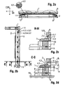
- Fig. 2 is a preferred embodiment of a lens frame according to the invention in front view, shown with an enlarged section in plan view and in two sectional images.
- the front and top views were drawn to scale on a 1.5: 1 scale to give an indication of the term "long and thin" fringe lens.
- a lens mount according to the invention is similar to a lens mount known from the prior art, as was explained in the introduction, designed so that a mounted fringe lens, which in the longitudinal direction, which is equal to the scan direction (SR) is scanned by a laser beam and thus describes a scan line that can be selectively deformed perpendicular to the scan direction SR, in the cross-scan direction CSR to linearize the scan line.
- SR scan direction
- the lens frame with a mounted strip lens 5 essentially comprises a strip lens 5, a spacer strip 7, a carrier strip 1, a base plate 2 and a base plate 9, and adjusting screws 4.1 and 4.2, via which the carrier strip 1 and consequently the spacer strip 7 and the strip lens 5 relative to the base plate 2 are deformable.
- Fig. 2 shows the essential part of the invention, the spacer bar 7, more precisely.
- the strip lens 5 is integrally connected via one of its optically inactive longitudinal sides 5.1 with a longitudinal side of the spacer strip 7.1, in particular glued.
- the spacer strip 7 has the length of the strip lens I L at least approximately the same length in order to be able to transmit bending forces acting on the entire length I L of the strip lens 5.
- the thickness d A can be varied and can be chosen as a function of the distance between the optical axis of the fringe lens 5.2 and a reference surface 10, on which the lens frame is mounted when integrated into an optical arrangement, or how much space near the fringe lens 5 is required for adjacent components.
- a lens frame according to the prior art can not, as advantageous according to a lens frame shown here, be mounted directly on the base plate 9 or in another embodiment directly on the base plate 2 on the reference surface 10, which for the dimensioning of the base plate 2 and optionally the base plate 9 is important. Explanations will be given later.
- the thickness of the spacer strip d A is preferably less than the height of the strip lens h L , with a sufficiently wide joint surface must be given to the strip lens 5 stable and mechanically fixed to the spacer bar 7 to connect.
- the Width of the spacer strip b A starting just behind the joining surface, is preferably decreasing.
- the spacer strip 7 has the lowest possible bending strength, but a high compressive strength.
- the low bending strength is achieved in particular by the fact that the spacer strip 7 is made slotted.
- the slots 14 are distributed over almost the entire length of the spacer bar 7 and preferably have only a greater distance there to each other, where provided for connection to the support bar 1 threaded holes 8.
- the slots 14 are open to one of the longitudinal side 7.1 opposite longitudinal side 7.2 and extend over the entire width b A.
- the material remaining below the slots 14, referred to below as the slot bottom has a constant residual thickness d Ar which is chosen to be as small as possible.
- the dependence of the bending stiffness of the dimensioning is given essentially by the thickness in the direction of an acting bending force, not the thickness of the spacer strip d A , but the residual thickness d Ar , for the flexural rigidity of the spacer bar 7 determines.
- the smaller the residual thickness d Ar the lower is its flexural rigidity.
- the thickness of the spacer strip d A can thus be varied, while maintaining the residual thickness d Ar , without the flexural rigidity of the spacer bar 7 is changed.
- the spacer bar 7 assumes a part of the function which a carrier strip 1 according to the lens frame known from the prior art has, namely the holding and the stabilization of the strip lens 5 within the lens frame and also during the preceding production.
- the support bar 1 is mounted, preferably, by multiple screwing by means of fixing screws 13th
- the carrier strip 1 is equal to a described lens frame, according to the prior art, by the selection of materials and their dimensions, in particular the thickness designed so that it has a flexural rigidity which allows a deformation by the adjustment of the screws 4.1, 4.2.
- the carrier strip 1 and the base plate 2 via a fixed bearing and a movable bearing in an adjustment distance a via locking screws 11 are connected to each other.
- the adjustment distance a is preferably ensured via a three-point support, the z. B. can be clamped by balls 12.
- the carrier strip 1 has over its length between the two bearings a series of alternately lowered through holes 3.1 and through threaded holes 3.2.
- first set screws 4.1 preferably cylinder head bolts are introduced, which engage on an outer surface of the base plate 2 provided in threaded holes (hereinafter referred to as threaded bores 8).
- second screws 4.2 preferably ball screws are introduced, which come to rest on the same outer surface. By tightening or loosening these second screws 4.2, the carrier strip 1 is pressed more or less away from the base plate 2.
- the carrier strip 1 and thus the strip lens 5 fixedly connected to the carrier strip 1 via the spacer strip 7 can be deformed in the sub-micron range.
- the base plate 2 has a very high rigidity, so that the adjustment path of the adjusting screws 4.1, 4.2 is fully incorporated in the deformation of the carrier strip 1.
- the base plate 2 In order to bring the base plate 2 in a defined position to a reference surface 10, the base plate 2, as well known from the prior art, could be mounted on the reference surface 10 via two lateral holders 6. Mechanically more stable and shortening the tolerance chain between base plate 2 and reference surface 10, however, is a direct attachment of the base plate 2 to the reference surface 10th Even more advantageous, however, is an attachment of the base plate 2 indirectly via a base plate 9, which is arranged between the base plate 2 and the reference surface 10. This has the advantage that an adjustment of the base plate 2 to the reference surface 10 is then not carried out solely by the displacement and tilting of the base plate 2, but is divided on the base plate 2 and the base plate 9.
- the base plate 9 can then be mounted on the reference surface 10 in such a way that it can be mounted with two degrees of freedom, namely in two axial directions, in the direction of the optical axis 5.2. and perpendicular to this, can be adjusted.
- the base plate 2 is also adjusted with two degrees of freedom in a direction perpendicular thereto and the axis perpendicular to the optical axis 5.2 axis direction.
- the strip lens 5 is positioned in its position relative to the remaining optical components of the optical arrangement.
Landscapes
- Physics & Mathematics (AREA)
- General Physics & Mathematics (AREA)
- Optics & Photonics (AREA)
- Lens Barrels (AREA)
- Mechanical Optical Scanning Systems (AREA)
- Mounting And Adjusting Of Optical Elements (AREA)
Applications Claiming Priority (2)
| Application Number | Priority Date | Filing Date | Title |
|---|---|---|---|
| DE102011012886A DE102011012886B3 (de) | 2011-03-01 | 2011-03-01 | Justierbare Linsenfassung für eine Streifenlinse |
| PCT/DE2012/100033 WO2012116693A2 (de) | 2011-03-01 | 2012-02-14 | Justierbare linsenfassung für eine streifenlinse |
Publications (2)
| Publication Number | Publication Date |
|---|---|
| EP2681603A2 EP2681603A2 (de) | 2014-01-08 |
| EP2681603B1 true EP2681603B1 (de) | 2015-01-14 |
Family
ID=45999182
Family Applications (1)
| Application Number | Title | Priority Date | Filing Date |
|---|---|---|---|
| EP12746004.6A Active EP2681603B1 (de) | 2011-03-01 | 2012-02-14 | Justierbare linsenfassung für eine streifenlinse |
Country Status (9)
Families Citing this family (3)
| Publication number | Priority date | Publication date | Assignee | Title |
|---|---|---|---|---|
| CN103676065B (zh) * | 2013-10-31 | 2016-01-06 | 中国科学院上海光学精密机械研究所 | 大口径透镜的调整固定装置 |
| DE102019102602B4 (de) | 2019-02-01 | 2020-12-31 | Jenoptik Optical Systems Gmbh | Optische Baugruppe mit einer Optikfassung und einer Streifenoptik |
| JP7358188B2 (ja) * | 2019-10-21 | 2023-10-10 | 株式会社ミツトヨ | 光学装置および光学式測定機 |
Family Cites Families (14)
| Publication number | Priority date | Publication date | Assignee | Title |
|---|---|---|---|---|
| GB2119952B (en) * | 1982-03-21 | 1986-03-05 | Konishiroku Photo Ind | Optical beam scanning apparatus |
| US7301554B2 (en) * | 2002-09-20 | 2007-11-27 | Ricoh Company, Ltd. | Light scanning device, scanning line adjusting method, scanning line adjusting control method, image forming apparatus, and image forming method |
| JP4340558B2 (ja) * | 2004-02-24 | 2009-10-07 | 株式会社リコー | 光走査装置及び画像形成装置 |
| US7684100B2 (en) * | 2004-11-26 | 2010-03-23 | Ricoh Company, Ltd. | Optical-element holding device, method of adjusting shape of optical element, optical-element shape adjusting device, method of correcting scanning line variation, optical scanning device, and image forming apparatus |
| JP4855693B2 (ja) * | 2005-02-21 | 2012-01-18 | 株式会社リコー | 光走査装置および画像形成装置 |
| JP4675247B2 (ja) * | 2005-04-20 | 2011-04-20 | 株式会社リコー | 走査光学系、光走査装置及び画像形成装置 |
| JP4654110B2 (ja) * | 2005-10-27 | 2011-03-16 | 株式会社リコー | 走査線調整装置、光走査装置及び画像形成装置 |
| JP5174324B2 (ja) * | 2006-02-17 | 2013-04-03 | 京セラドキュメントソリューションズ株式会社 | 光素子保持体、及び光走査ユニット |
| JP4903455B2 (ja) * | 2006-03-03 | 2012-03-28 | 株式会社リコー | 光走査装置および画像形成装置 |
| JP4847201B2 (ja) * | 2006-04-27 | 2011-12-28 | 株式会社リコー | 光源システム、光走査装置、画像形成装置、光量制御方法、光走査方法、及び画像形成方法 |
| JP2008216438A (ja) | 2007-03-01 | 2008-09-18 | Ricoh Co Ltd | 光走査装置および画像形成装置 |
| JP4815372B2 (ja) * | 2007-03-16 | 2011-11-16 | 株式会社リコー | 光学素子ユニット、光走査装置、及び画像形成装置 |
| JP5354323B2 (ja) * | 2007-07-02 | 2013-11-27 | 株式会社リコー | 光走査装置及び画像形成装置 |
| JP5355253B2 (ja) * | 2009-06-30 | 2013-11-27 | キヤノン株式会社 | 光走査装置 |
-
2011
- 2011-03-01 DE DE102011012886A patent/DE102011012886B3/de not_active Expired - Fee Related
-
2012
- 2012-02-02 TW TW101103352A patent/TWI531825B/zh active
- 2012-02-14 JP JP2013555756A patent/JP5941929B2/ja active Active
- 2012-02-14 EP EP12746004.6A patent/EP2681603B1/de active Active
- 2012-02-14 WO PCT/DE2012/100033 patent/WO2012116693A2/de active Application Filing
- 2012-02-14 KR KR1020137023328A patent/KR101776985B1/ko active Active
- 2012-02-14 CN CN201280011411.XA patent/CN103477262B/zh active Active
-
2013
- 2013-07-09 US US13/937,775 patent/US9151926B2/en active Active
- 2013-08-26 IL IL228121A patent/IL228121A0/en unknown
Also Published As
| Publication number | Publication date |
|---|---|
| CN103477262A (zh) | 2013-12-25 |
| WO2012116693A4 (de) | 2013-01-10 |
| US20130293973A1 (en) | 2013-11-07 |
| DE102011012886B3 (de) | 2012-05-16 |
| EP2681603A2 (de) | 2014-01-08 |
| JP5941929B2 (ja) | 2016-06-29 |
| CN103477262B (zh) | 2016-01-20 |
| TW201245794A (en) | 2012-11-16 |
| WO2012116693A2 (de) | 2012-09-07 |
| IL228121A0 (en) | 2013-09-30 |
| JP2014513314A (ja) | 2014-05-29 |
| WO2012116693A3 (de) | 2012-11-22 |
| KR101776985B1 (ko) | 2017-09-08 |
| TWI531825B (zh) | 2016-05-01 |
| US9151926B2 (en) | 2015-10-06 |
| KR20140025344A (ko) | 2014-03-04 |
Similar Documents
| Publication | Publication Date | Title |
|---|---|---|
| EP3610315B1 (de) | Mikromechanische spiegelvorrichtung | |
| EP2843454A1 (de) | Optische Baugruppe mit einer Fassung mit Verbindungseinheiten gerichteter Nachgiebigkeit | |
| EP2520384B1 (de) | Windewerkzeug für Federwindemaschinen | |
| EP3362213B1 (de) | Schneidplatte, werkzeughalter und werkzeug zur spanenden bearbeitung eines werkstücks | |
| DE202018105381U1 (de) | Koppelungsvorrichtung für Lineale | |
| EP2681603B1 (de) | Justierbare linsenfassung für eine streifenlinse | |
| EP1711288B2 (de) | Fügeeinrichtung | |
| DE102005039279B4 (de) | Linearführung | |
| DE102016102469B3 (de) | Optische Fassung mit wenigstens einer Klemmeinheit mit Klebespalt | |
| DE102013109605B3 (de) | Optische Baugruppe mit einer monolithischen Fassung mit in einer gleichen Richtung wirkenden Stellschrauben | |
| DE3151275A1 (de) | Befestigungsvorrichtung fuer werkzeuge | |
| EP1548483B1 (de) | Mikroskopobjektiv mit axial verstellbaren Korrekturfassungen | |
| DE102018132838A1 (de) | Ultraschallschweißanlage mit Halterung | |
| DE102011085793A1 (de) | Halterungsvorrichtung zum Haltern eines Kabels oder einer Leitung an einer Strukturkomponente eines Luft- oder Raumfahrzeugs sowie Luft- oder Raumfahrzeug | |
| DE19827778A1 (de) | Kurzklemmhalter mit radialer Feinverstellung | |
| DE102014116708A1 (de) | Aktorvorrichtung | |
| DE112023000310T5 (de) | Modenmischer | |
| DE102015116584B3 (de) | Justierbare Linsenfassung | |
| EP2650725A2 (de) | Haltevorrichtung zum Befestigen von Kamerazubehörteilen | |
| DE102015101387B3 (de) | Optische Fassung mit wenigstens einer Klemmeinheit mit einer Membranfeder | |
| DE102013114822B3 (de) | Zweiachsige Kippvorrichtung | |
| DE102018103053B3 (de) | Bauraumoptimierte Linsenfassung mit elastischen Verbindungsstrukturen | |
| DE4209668A1 (de) | Steuergerät, insbesondere zur Fernbedienung von hydraulischen Komponenten | |
| DE102015101384B3 (de) | Optische Fassung mit wenigstens einer Klemmeinheit mit einer Druckschraube | |
| DE102015115930B3 (de) | Versteifte Linsenfassung |
Legal Events
| Date | Code | Title | Description |
|---|---|---|---|
| PUAI | Public reference made under article 153(3) epc to a published international application that has entered the european phase |
Free format text: ORIGINAL CODE: 0009012 |
|
| 17P | Request for examination filed |
Effective date: 20130926 |
|
| AK | Designated contracting states |
Kind code of ref document: A2 Designated state(s): AL AT BE BG CH CY CZ DE DK EE ES FI FR GB GR HR HU IE IS IT LI LT LU LV MC MK MT NL NO PL PT RO RS SE SI SK SM TR |
|
| DAX | Request for extension of the european patent (deleted) | ||
| GRAP | Despatch of communication of intention to grant a patent |
Free format text: ORIGINAL CODE: EPIDOSNIGR1 |
|
| INTG | Intention to grant announced |
Effective date: 20140903 |
|
| GRAS | Grant fee paid |
Free format text: ORIGINAL CODE: EPIDOSNIGR3 |
|
| GRAA | (expected) grant |
Free format text: ORIGINAL CODE: 0009210 |
|
| AK | Designated contracting states |
Kind code of ref document: B1 Designated state(s): AL AT BE BG CH CY CZ DE DK EE ES FI FR GB GR HR HU IE IS IT LI LT LU LV MC MK MT NL NO PL PT RO RS SE SI SK SM TR |
|
| REG | Reference to a national code |
Ref country code: GB Ref legal event code: FG4D Free format text: NOT ENGLISH |
|
| REG | Reference to a national code |
Ref country code: CH Ref legal event code: EP |
|
| REG | Reference to a national code |
Ref country code: IE Ref legal event code: FG4D Free format text: LANGUAGE OF EP DOCUMENT: GERMAN |
|
| REG | Reference to a national code |
Ref country code: AT Ref legal event code: REF Ref document number: 707351 Country of ref document: AT Kind code of ref document: T Effective date: 20150215 |
|
| REG | Reference to a national code |
Ref country code: DE Ref legal event code: R096 Ref document number: 502012002129 Country of ref document: DE Effective date: 20150305 |
|
| REG | Reference to a national code |
Ref country code: NL Ref legal event code: VDEP Effective date: 20150114 |
|
| REG | Reference to a national code |
Ref country code: LT Ref legal event code: MG4D |
|
| PG25 | Lapsed in a contracting state [announced via postgrant information from national office to epo] |
Ref country code: BE Free format text: LAPSE BECAUSE OF NON-PAYMENT OF DUE FEES Effective date: 20150228 |
|
| PG25 | Lapsed in a contracting state [announced via postgrant information from national office to epo] |
Ref country code: SE Free format text: LAPSE BECAUSE OF FAILURE TO SUBMIT A TRANSLATION OF THE DESCRIPTION OR TO PAY THE FEE WITHIN THE PRESCRIBED TIME-LIMIT Effective date: 20150114 Ref country code: ES Free format text: LAPSE BECAUSE OF FAILURE TO SUBMIT A TRANSLATION OF THE DESCRIPTION OR TO PAY THE FEE WITHIN THE PRESCRIBED TIME-LIMIT Effective date: 20150114 Ref country code: FI Free format text: LAPSE BECAUSE OF FAILURE TO SUBMIT A TRANSLATION OF THE DESCRIPTION OR TO PAY THE FEE WITHIN THE PRESCRIBED TIME-LIMIT Effective date: 20150114 Ref country code: HR Free format text: LAPSE BECAUSE OF FAILURE TO SUBMIT A TRANSLATION OF THE DESCRIPTION OR TO PAY THE FEE WITHIN THE PRESCRIBED TIME-LIMIT Effective date: 20150114 Ref country code: NO Free format text: LAPSE BECAUSE OF FAILURE TO SUBMIT A TRANSLATION OF THE DESCRIPTION OR TO PAY THE FEE WITHIN THE PRESCRIBED TIME-LIMIT Effective date: 20150414 Ref country code: LT Free format text: LAPSE BECAUSE OF FAILURE TO SUBMIT A TRANSLATION OF THE DESCRIPTION OR TO PAY THE FEE WITHIN THE PRESCRIBED TIME-LIMIT Effective date: 20150114 Ref country code: BG Free format text: LAPSE BECAUSE OF FAILURE TO SUBMIT A TRANSLATION OF THE DESCRIPTION OR TO PAY THE FEE WITHIN THE PRESCRIBED TIME-LIMIT Effective date: 20150414 |
|
| PG25 | Lapsed in a contracting state [announced via postgrant information from national office to epo] |
Ref country code: NL Free format text: LAPSE BECAUSE OF FAILURE TO SUBMIT A TRANSLATION OF THE DESCRIPTION OR TO PAY THE FEE WITHIN THE PRESCRIBED TIME-LIMIT Effective date: 20150114 Ref country code: LV Free format text: LAPSE BECAUSE OF FAILURE TO SUBMIT A TRANSLATION OF THE DESCRIPTION OR TO PAY THE FEE WITHIN THE PRESCRIBED TIME-LIMIT Effective date: 20150114 Ref country code: PL Free format text: LAPSE BECAUSE OF FAILURE TO SUBMIT A TRANSLATION OF THE DESCRIPTION OR TO PAY THE FEE WITHIN THE PRESCRIBED TIME-LIMIT Effective date: 20150114 Ref country code: IS Free format text: LAPSE BECAUSE OF FAILURE TO SUBMIT A TRANSLATION OF THE DESCRIPTION OR TO PAY THE FEE WITHIN THE PRESCRIBED TIME-LIMIT Effective date: 20150514 Ref country code: GR Free format text: LAPSE BECAUSE OF FAILURE TO SUBMIT A TRANSLATION OF THE DESCRIPTION OR TO PAY THE FEE WITHIN THE PRESCRIBED TIME-LIMIT Effective date: 20150415 Ref country code: RS Free format text: LAPSE BECAUSE OF FAILURE TO SUBMIT A TRANSLATION OF THE DESCRIPTION OR TO PAY THE FEE WITHIN THE PRESCRIBED TIME-LIMIT Effective date: 20150114 |
|
| REG | Reference to a national code |
Ref country code: CH Ref legal event code: PL |
|
| REG | Reference to a national code |
Ref country code: DE Ref legal event code: R097 Ref document number: 502012002129 Country of ref document: DE |
|
| PG25 | Lapsed in a contracting state [announced via postgrant information from national office to epo] |
Ref country code: CH Free format text: LAPSE BECAUSE OF NON-PAYMENT OF DUE FEES Effective date: 20150228 Ref country code: LI Free format text: LAPSE BECAUSE OF NON-PAYMENT OF DUE FEES Effective date: 20150228 Ref country code: EE Free format text: LAPSE BECAUSE OF FAILURE TO SUBMIT A TRANSLATION OF THE DESCRIPTION OR TO PAY THE FEE WITHIN THE PRESCRIBED TIME-LIMIT Effective date: 20150114 Ref country code: MC Free format text: LAPSE BECAUSE OF FAILURE TO SUBMIT A TRANSLATION OF THE DESCRIPTION OR TO PAY THE FEE WITHIN THE PRESCRIBED TIME-LIMIT Effective date: 20150114 Ref country code: CZ Free format text: LAPSE BECAUSE OF FAILURE TO SUBMIT A TRANSLATION OF THE DESCRIPTION OR TO PAY THE FEE WITHIN THE PRESCRIBED TIME-LIMIT Effective date: 20150114 Ref country code: DK Free format text: LAPSE BECAUSE OF FAILURE TO SUBMIT A TRANSLATION OF THE DESCRIPTION OR TO PAY THE FEE WITHIN THE PRESCRIBED TIME-LIMIT Effective date: 20150114 Ref country code: SK Free format text: LAPSE BECAUSE OF FAILURE TO SUBMIT A TRANSLATION OF THE DESCRIPTION OR TO PAY THE FEE WITHIN THE PRESCRIBED TIME-LIMIT Effective date: 20150114 Ref country code: RO Free format text: LAPSE BECAUSE OF FAILURE TO SUBMIT A TRANSLATION OF THE DESCRIPTION OR TO PAY THE FEE WITHIN THE PRESCRIBED TIME-LIMIT Effective date: 20150114 |
|
| REG | Reference to a national code |
Ref country code: IE Ref legal event code: MM4A |
|
| PLBE | No opposition filed within time limit |
Free format text: ORIGINAL CODE: 0009261 |
|
| STAA | Information on the status of an ep patent application or granted ep patent |
Free format text: STATUS: NO OPPOSITION FILED WITHIN TIME LIMIT |
|
| 26N | No opposition filed |
Effective date: 20151015 |
|
| PG25 | Lapsed in a contracting state [announced via postgrant information from national office to epo] |
Ref country code: IT Free format text: LAPSE BECAUSE OF FAILURE TO SUBMIT A TRANSLATION OF THE DESCRIPTION OR TO PAY THE FEE WITHIN THE PRESCRIBED TIME-LIMIT Effective date: 20150114 |
|
| PG25 | Lapsed in a contracting state [announced via postgrant information from national office to epo] |
Ref country code: IE Free format text: LAPSE BECAUSE OF NON-PAYMENT OF DUE FEES Effective date: 20150214 |
|
| REG | Reference to a national code |
Ref country code: FR Ref legal event code: PLFP Year of fee payment: 5 |
|
| PG25 | Lapsed in a contracting state [announced via postgrant information from national office to epo] |
Ref country code: SI Free format text: LAPSE BECAUSE OF FAILURE TO SUBMIT A TRANSLATION OF THE DESCRIPTION OR TO PAY THE FEE WITHIN THE PRESCRIBED TIME-LIMIT Effective date: 20150114 |
|
| PG25 | Lapsed in a contracting state [announced via postgrant information from national office to epo] |
Ref country code: MT Free format text: LAPSE BECAUSE OF FAILURE TO SUBMIT A TRANSLATION OF THE DESCRIPTION OR TO PAY THE FEE WITHIN THE PRESCRIBED TIME-LIMIT Effective date: 20150114 |
|
| REG | Reference to a national code |
Ref country code: FR Ref legal event code: PLFP Year of fee payment: 6 |
|
| PGFP | Annual fee paid to national office [announced via postgrant information from national office to epo] |
Ref country code: FR Payment date: 20170220 Year of fee payment: 6 |
|
| PG25 | Lapsed in a contracting state [announced via postgrant information from national office to epo] |
Ref country code: SM Free format text: LAPSE BECAUSE OF FAILURE TO SUBMIT A TRANSLATION OF THE DESCRIPTION OR TO PAY THE FEE WITHIN THE PRESCRIBED TIME-LIMIT Effective date: 20150114 Ref country code: HU Free format text: LAPSE BECAUSE OF FAILURE TO SUBMIT A TRANSLATION OF THE DESCRIPTION OR TO PAY THE FEE WITHIN THE PRESCRIBED TIME-LIMIT; INVALID AB INITIO Effective date: 20120214 |
|
| PGFP | Annual fee paid to national office [announced via postgrant information from national office to epo] |
Ref country code: GB Payment date: 20170221 Year of fee payment: 6 |
|
| PG25 | Lapsed in a contracting state [announced via postgrant information from national office to epo] |
Ref country code: CY Free format text: LAPSE BECAUSE OF FAILURE TO SUBMIT A TRANSLATION OF THE DESCRIPTION OR TO PAY THE FEE WITHIN THE PRESCRIBED TIME-LIMIT Effective date: 20150114 |
|
| PG25 | Lapsed in a contracting state [announced via postgrant information from national office to epo] |
Ref country code: PT Free format text: LAPSE BECAUSE OF FAILURE TO SUBMIT A TRANSLATION OF THE DESCRIPTION OR TO PAY THE FEE WITHIN THE PRESCRIBED TIME-LIMIT Effective date: 20150514 |
|
| PG25 | Lapsed in a contracting state [announced via postgrant information from national office to epo] |
Ref country code: TR Free format text: LAPSE BECAUSE OF FAILURE TO SUBMIT A TRANSLATION OF THE DESCRIPTION OR TO PAY THE FEE WITHIN THE PRESCRIBED TIME-LIMIT Effective date: 20150114 |
|
| PG25 | Lapsed in a contracting state [announced via postgrant information from national office to epo] |
Ref country code: LU Free format text: LAPSE BECAUSE OF NON-PAYMENT OF DUE FEES Effective date: 20150214 |
|
| REG | Reference to a national code |
Ref country code: AT Ref legal event code: MM01 Ref document number: 707351 Country of ref document: AT Kind code of ref document: T Effective date: 20170214 |
|
| PG25 | Lapsed in a contracting state [announced via postgrant information from national office to epo] |
Ref country code: AT Free format text: LAPSE BECAUSE OF NON-PAYMENT OF DUE FEES Effective date: 20170214 |
|
| PG25 | Lapsed in a contracting state [announced via postgrant information from national office to epo] |
Ref country code: MK Free format text: LAPSE BECAUSE OF FAILURE TO SUBMIT A TRANSLATION OF THE DESCRIPTION OR TO PAY THE FEE WITHIN THE PRESCRIBED TIME-LIMIT Effective date: 20150114 |
|
| GBPC | Gb: european patent ceased through non-payment of renewal fee |
Effective date: 20180214 |
|
| PG25 | Lapsed in a contracting state [announced via postgrant information from national office to epo] |
Ref country code: AL Free format text: LAPSE BECAUSE OF FAILURE TO SUBMIT A TRANSLATION OF THE DESCRIPTION OR TO PAY THE FEE WITHIN THE PRESCRIBED TIME-LIMIT Effective date: 20150114 |
|
| REG | Reference to a national code |
Ref country code: FR Ref legal event code: ST Effective date: 20181031 |
|
| PG25 | Lapsed in a contracting state [announced via postgrant information from national office to epo] |
Ref country code: FR Free format text: LAPSE BECAUSE OF NON-PAYMENT OF DUE FEES Effective date: 20180228 Ref country code: GB Free format text: LAPSE BECAUSE OF NON-PAYMENT OF DUE FEES Effective date: 20180214 |
|
| PGFP | Annual fee paid to national office [announced via postgrant information from national office to epo] |
Ref country code: DE Payment date: 20250218 Year of fee payment: 14 |