EP2681603B1 - Adjustable lens mount for a strip lens - Google Patents
Adjustable lens mount for a strip lens Download PDFInfo
- Publication number
- EP2681603B1 EP2681603B1 EP12746004.6A EP12746004A EP2681603B1 EP 2681603 B1 EP2681603 B1 EP 2681603B1 EP 12746004 A EP12746004 A EP 12746004A EP 2681603 B1 EP2681603 B1 EP 2681603B1
- Authority
- EP
- European Patent Office
- Prior art keywords
- strip
- lens
- spacer
- lens mount
- base plate
- Prior art date
- Legal status (The legal status is an assumption and is not a legal conclusion. Google has not performed a legal analysis and makes no representation as to the accuracy of the status listed.)
- Active
Links
- 125000006850 spacer group Chemical group 0.000 claims description 52
- 230000003287 optical effect Effects 0.000 claims description 22
- 230000003247 decreasing effect Effects 0.000 claims description 4
- 238000005452 bending Methods 0.000 description 11
- 238000005304 joining Methods 0.000 description 6
- 238000009434 installation Methods 0.000 description 3
- 238000004891 communication Methods 0.000 description 2
- 238000006073 displacement reaction Methods 0.000 description 2
- 238000003384 imaging method Methods 0.000 description 2
- 230000000694 effects Effects 0.000 description 1
- 238000004519 manufacturing process Methods 0.000 description 1
- 238000005457 optimization Methods 0.000 description 1
- 238000004904 shortening Methods 0.000 description 1
- 230000006641 stabilisation Effects 0.000 description 1
- 238000011105 stabilization Methods 0.000 description 1
Images


Classifications
-
- G—PHYSICS
- G02—OPTICS
- G02B—OPTICAL ELEMENTS, SYSTEMS OR APPARATUS
- G02B7/00—Mountings, adjusting means, or light-tight connections, for optical elements
- G02B7/02—Mountings, adjusting means, or light-tight connections, for optical elements for lenses
- G02B7/023—Mountings, adjusting means, or light-tight connections, for optical elements for lenses permitting adjustment
-
- G—PHYSICS
- G02—OPTICS
- G02B—OPTICAL ELEMENTS, SYSTEMS OR APPARATUS
- G02B26/00—Optical devices or arrangements for the control of light using movable or deformable optical elements
- G02B26/08—Optical devices or arrangements for the control of light using movable or deformable optical elements for controlling the direction of light
- G02B26/10—Scanning systems
- G02B26/12—Scanning systems using multifaceted mirrors
- G02B26/125—Details of the optical system between the polygonal mirror and the image plane
-
- G—PHYSICS
- G02—OPTICS
- G02B—OPTICAL ELEMENTS, SYSTEMS OR APPARATUS
- G02B26/00—Optical devices or arrangements for the control of light using movable or deformable optical elements
- G02B26/08—Optical devices or arrangements for the control of light using movable or deformable optical elements for controlling the direction of light
- G02B26/10—Scanning systems
- G02B26/12—Scanning systems using multifaceted mirrors
- G02B26/127—Adaptive control of the scanning light beam, e.g. using the feedback from one or more detectors
-
- G—PHYSICS
- G02—OPTICS
- G02B—OPTICAL ELEMENTS, SYSTEMS OR APPARATUS
- G02B27/00—Optical systems or apparatus not provided for by any of the groups G02B1/00 - G02B26/00, G02B30/00
- G02B27/0025—Optical systems or apparatus not provided for by any of the groups G02B1/00 - G02B26/00, G02B30/00 for optical correction, e.g. distorsion, aberration
- G02B27/0031—Optical systems or apparatus not provided for by any of the groups G02B1/00 - G02B26/00, G02B30/00 for optical correction, e.g. distorsion, aberration for scanning purposes
Definitions
- the invention relates to an adjustable lens mount for a fringe lens, in particular in the form of a long, thin cylindrical lens, as used in scan lenses in laser material processing and in the printing industry.
- the last optically imaging element within an optical arrangement, which focuses the laser beam, which scans the strip lens in the direction of its longitudinal extent (scan direction), into an image plane in which the workpiece to be processed is arranged.
- the scan line described by the focus on the workpiece is theoretically a straight line, but it deviates in the direction of the relative movement between the scan line and the workpiece (cross-scan direction), perpendicular to the scan direction, due to tolerances of the components taking part in the figure from an ideal straight line.
- cross-scan direction perpendicular to the scan direction
- a cylinder lens is distinguished in its design compared to conventional rotationally symmetrical lenses in that it has over its entire length a same cross-section perpendicular to its longitudinal extent and thus a constant thickness (extension in the direction of the optical axis). This peculiarity makes them predestined, as long as they are relatively long and thin, by adjustment via a targeted local deformation in the submicrometer range, which can be effected at any point along the length with an equally large displacement, to manipulate the beam imaging, that of the focus linearize the described scan line.
- the carrier strip must be in accordance with the available Justier conceptn or Justier admir be deformed, which is achieved by selecting an optimized bending stiffness of the carrier strip, by the choice of a material with a suitable modulus of elasticity and a correlating moment of inertia of the carrier strip, determined by the dimensioning, in particular the thickness.
- such a support bar is made wider than the required joining surface is wide, over which the strip lens is firmly connected to the carrier strip to provide on the opposite side of the joining surface a sufficiently wide mounting surface available at the a variety of Adjusting screws along the longitudinal extent of the carrier strip can attack to fix them relative to a rigid base plate adjustable.
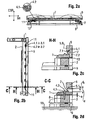
- Fig. 1 is a lens frame with strip lens, as known from the prior art, shown. Shown are a perspective view in magnification 1: 2 and two sectional views (not to scale).
- the lens frame essentially consists of an elongate carrier strip 1 with a joining surface on which a strip lens 5 can be applied over its entire length and a rigid base plate 2, which is provided on the free side of the carrier strip 1 opposite the joining surface.
- the base plate 2 is slightly longer than the carrier strip 1 and has along its length a number of alternately arranged lowered through holes 3.1 and through threaded holes 3.2.
- the carrier strip 1 and the base plate 2 are mounted at a predetermined adjustment distance from each other on lateral holders 6, via which the lens frame is mounted on a reference surface 10, e.g. is provided on a housing of a scanning lens, can be attached.
- first set screws 4.1 preferably cylinder head bolts are introduced, which engage on the free outer surface of the carrier strip 1 in provided threaded holes (hereinafter referred to as threaded holes 8).
- second screws 4.2 preferably ball screws are introduced, which come to the free outer surface of the carrier strip 1 to the plant.
- second screws 4.2 By a differentiated tightening of individual second screws 4.2, the carrier strip 1 is pressed from the base plate 2 locally more or less away.
- the carrier strip 1 and thus the firmly connected to the carrier strip 1 strip lens 5 in the submicron range in the cross-scan direction (CSR) are wavy deformed.
- a disadvantage of the lens frame described is the space required for this purpose immediately adjacent to the strip lens 5.
- the carrier strip 1 is in the direction of the optical axis which is equal to the cross-scan direction (CSR). significantly beyond the thickness of the strip lens 5 also extends. Thus, it is not possible to arrange another optical or mechanical component in this area.
- the carrier strip 1 may limit the beam path undesirable.
- the mechanical connection between the base plate 2 and a reference surface 10 can only be made via lateral holder 6 to allow access to the screws 4.1, 4.2. Such attachment requires a particularly high flexural rigidity of the base plate 2.
- the US 2006/132880 A1 discloses an adjustable lens frame for a strip lens having a support bar communicating with one of its longitudinal sides with an optically ineffective longitudinal side of a strip lens to be gripped, and a base plate having at its ends to the ends of the support strip at a fixed adjustment distance arranged and fixed by fixing screws to each other and between the ends of first acting as a lag screws and second set screws acting as pressure screws, which are arranged alternately in a row, are in communication with the carrier bar, so that the carrier strip and consequently the strip lens on Their length in the direction of action of the first and second screws, can be deformed perpendicular to its optical axis.
- the invention is based on the object to find an improved lens frame for a strip lens, which requires less space immediately adjacent to a captured with her strip lens.
- the requirements for a base plate of the lens frame should be lower, to this with less
- the strip lens 5 and the carrier strip 1 are not directly but indirectly via a spacer bar 7 in connection, wherein the spacer bar 7 is integrally connected on one longitudinal side 7.1 with the longitudinal side of the strip lens 5.1 and on the opposite longitudinal side of the spacer bar 7.2 with the longitudinal side of the carrier strip is firmly connected.
- This spacer strip 7 has the function necessary for the components of the lens frame space to shift away from the strip lens 5. To keep the forces required for an adjustment of the screws 4.1 and 4.2 low, the spacer bar 7 has the lowest possible bending strength, but the highest possible compressive strength.
- the spacer strip 7 which consists of a pressure-resistant material, has only a low flexural strength
- a plurality of slits 14 open to the opposite longitudinal side 7.2 are introduced into the latter. They extend in the direction of action of the screws 4.1, 4.2 over the entire width b A of the spacer bar 7, whereby the dependence of the bending strength of the spacer bar 7 of the geometry, determined by the remaining residual thickness d Ar of the slot bottom 14 remaining below the slots.
- the carrier strip 1, arranged in a row, alternately through holes 3.1 and through threaded holes 3.2 and the first screws 4.1 engage through the through holes 3.1 in threaded provided holes 8 of the base plate 2, while the second screws 4.2 pressed by the threaded holes 3.2 pressed against the base plate 2.
- the necessary adjustment distance a is advantageously determined by a three-point support.
- the carrier strip 1 and the base plate 2 are advantageously connected at their ends via a fixed and a movable bearing.
- the base plate 2 can be mounted directly on a reference surface 10 with at least two degrees of freedom for adjustment. It can thus be made thinner, comparatively to a connection to the reference surface 10 via lateral holders 6.
- the base plate 2 By the base plate 2 indirectly via a base plate 9 is mounted on a reference surface 10, the base plate 2 can be adjusted relative to the reference surface 10 by advantageously the base plate 9 with two degrees of freedom to the reference surface 10 and the base plate 2 with two further degrees of freedom to the base plate 9 adjustable is executed.
- the thickness of the spacer strip d A is advantageously adaptable at a different residual thickness d Ar at each given different interfaces.
- the width of the spacer bar b A is advantageously less than the height of the strip lens h L.
- the core idea of the invention is to provide a spacer strip between a deformable carrier strip and a strip lens which has the lowest possible bending stiffness.
- This spacer bar has the function of firmly connecting the strip lens and the carrier strip in order to transmit a deformation of the carrier strip to the strip lens.
- the installation space required for the lens mount is shifted as far as possible away from the optical axis, so that space is created for the arrangement of other mounted optical components.
- the lens frame will be explained in more detail below by way of example with reference to the drawings.
- the lens frame shown relates to a lens frame as known from the prior art and as has already been explained in detail in the description of the prior art.
- Fig. 2 is a preferred embodiment of a lens frame according to the invention in front view, shown with an enlarged section in plan view and in two sectional images.
- the front and top views were drawn to scale on a 1.5: 1 scale to give an indication of the term "long and thin" fringe lens.
- a lens mount according to the invention is similar to a lens mount known from the prior art, as was explained in the introduction, designed so that a mounted fringe lens, which in the longitudinal direction, which is equal to the scan direction (SR) is scanned by a laser beam and thus describes a scan line that can be selectively deformed perpendicular to the scan direction SR, in the cross-scan direction CSR to linearize the scan line.
- SR scan direction
- the lens frame with a mounted strip lens 5 essentially comprises a strip lens 5, a spacer strip 7, a carrier strip 1, a base plate 2 and a base plate 9, and adjusting screws 4.1 and 4.2, via which the carrier strip 1 and consequently the spacer strip 7 and the strip lens 5 relative to the base plate 2 are deformable.
- Fig. 2 shows the essential part of the invention, the spacer bar 7, more precisely.
- the strip lens 5 is integrally connected via one of its optically inactive longitudinal sides 5.1 with a longitudinal side of the spacer strip 7.1, in particular glued.
- the spacer strip 7 has the length of the strip lens I L at least approximately the same length in order to be able to transmit bending forces acting on the entire length I L of the strip lens 5.
- the thickness d A can be varied and can be chosen as a function of the distance between the optical axis of the fringe lens 5.2 and a reference surface 10, on which the lens frame is mounted when integrated into an optical arrangement, or how much space near the fringe lens 5 is required for adjacent components.
- a lens frame according to the prior art can not, as advantageous according to a lens frame shown here, be mounted directly on the base plate 9 or in another embodiment directly on the base plate 2 on the reference surface 10, which for the dimensioning of the base plate 2 and optionally the base plate 9 is important. Explanations will be given later.
- the thickness of the spacer strip d A is preferably less than the height of the strip lens h L , with a sufficiently wide joint surface must be given to the strip lens 5 stable and mechanically fixed to the spacer bar 7 to connect.
- the Width of the spacer strip b A starting just behind the joining surface, is preferably decreasing.
- the spacer strip 7 has the lowest possible bending strength, but a high compressive strength.
- the low bending strength is achieved in particular by the fact that the spacer strip 7 is made slotted.
- the slots 14 are distributed over almost the entire length of the spacer bar 7 and preferably have only a greater distance there to each other, where provided for connection to the support bar 1 threaded holes 8.
- the slots 14 are open to one of the longitudinal side 7.1 opposite longitudinal side 7.2 and extend over the entire width b A.
- the material remaining below the slots 14, referred to below as the slot bottom has a constant residual thickness d Ar which is chosen to be as small as possible.
- the dependence of the bending stiffness of the dimensioning is given essentially by the thickness in the direction of an acting bending force, not the thickness of the spacer strip d A , but the residual thickness d Ar , for the flexural rigidity of the spacer bar 7 determines.
- the smaller the residual thickness d Ar the lower is its flexural rigidity.
- the thickness of the spacer strip d A can thus be varied, while maintaining the residual thickness d Ar , without the flexural rigidity of the spacer bar 7 is changed.
- the spacer bar 7 assumes a part of the function which a carrier strip 1 according to the lens frame known from the prior art has, namely the holding and the stabilization of the strip lens 5 within the lens frame and also during the preceding production.
- the support bar 1 is mounted, preferably, by multiple screwing by means of fixing screws 13th
- the carrier strip 1 is equal to a described lens frame, according to the prior art, by the selection of materials and their dimensions, in particular the thickness designed so that it has a flexural rigidity which allows a deformation by the adjustment of the screws 4.1, 4.2.
- the carrier strip 1 and the base plate 2 via a fixed bearing and a movable bearing in an adjustment distance a via locking screws 11 are connected to each other.
- the adjustment distance a is preferably ensured via a three-point support, the z. B. can be clamped by balls 12.
- the carrier strip 1 has over its length between the two bearings a series of alternately lowered through holes 3.1 and through threaded holes 3.2.
- first set screws 4.1 preferably cylinder head bolts are introduced, which engage on an outer surface of the base plate 2 provided in threaded holes (hereinafter referred to as threaded bores 8).
- second screws 4.2 preferably ball screws are introduced, which come to rest on the same outer surface. By tightening or loosening these second screws 4.2, the carrier strip 1 is pressed more or less away from the base plate 2.
- the carrier strip 1 and thus the strip lens 5 fixedly connected to the carrier strip 1 via the spacer strip 7 can be deformed in the sub-micron range.
- the base plate 2 has a very high rigidity, so that the adjustment path of the adjusting screws 4.1, 4.2 is fully incorporated in the deformation of the carrier strip 1.
- the base plate 2 In order to bring the base plate 2 in a defined position to a reference surface 10, the base plate 2, as well known from the prior art, could be mounted on the reference surface 10 via two lateral holders 6. Mechanically more stable and shortening the tolerance chain between base plate 2 and reference surface 10, however, is a direct attachment of the base plate 2 to the reference surface 10th Even more advantageous, however, is an attachment of the base plate 2 indirectly via a base plate 9, which is arranged between the base plate 2 and the reference surface 10. This has the advantage that an adjustment of the base plate 2 to the reference surface 10 is then not carried out solely by the displacement and tilting of the base plate 2, but is divided on the base plate 2 and the base plate 9.
- the base plate 9 can then be mounted on the reference surface 10 in such a way that it can be mounted with two degrees of freedom, namely in two axial directions, in the direction of the optical axis 5.2. and perpendicular to this, can be adjusted.
- the base plate 2 is also adjusted with two degrees of freedom in a direction perpendicular thereto and the axis perpendicular to the optical axis 5.2 axis direction.
- the strip lens 5 is positioned in its position relative to the remaining optical components of the optical arrangement.
Landscapes
- Physics & Mathematics (AREA)
- General Physics & Mathematics (AREA)
- Optics & Photonics (AREA)
- Lens Barrels (AREA)
- Mechanical Optical Scanning Systems (AREA)
- Mounting And Adjusting Of Optical Elements (AREA)
Description
Die Erfindung betrifft eine justierbare Linsenfassung für eine Streifenlinse, insbesondere in Form einer langen, dünnen Zylinderlinse, wie sie in Scan-Objektiven bei der Lasermaterialbearbeitung und in der Druckindustrie zur Anwendung kommt.The invention relates to an adjustable lens mount for a fringe lens, in particular in the form of a long, thin cylindrical lens, as used in scan lenses in laser material processing and in the printing industry.
Sie bildet hier in der Regel innerhalb einer optischen Anordnung das letzte optisch abbildende Element, die den Laserstrahl, welcher die Streifenlinse scannend in Richtung deren Längsausdehnung (Scan-Richtung) überstreicht, in eine Bildebene, in der das zu bearbeitende Werkstück angeordnet ist, fokussiert.Here, as a rule, it forms the last optically imaging element within an optical arrangement, which focuses the laser beam, which scans the strip lens in the direction of its longitudinal extent (scan direction), into an image plane in which the workpiece to be processed is arranged.
Die dabei durch den Fokus auf dem Werkstück beschriebene Scan-Linie ist theoretisch eine Gerade, sie weicht praktisch jedoch in Richtung der Relativbewegung zwischen der Scan-Linie und dem Werkstück (Cross-Scan-Richtung), senkrecht zur Scan-Richtung, aufgrund von Toleranzen der an der Abbildung teilnehmenden Bauteile von einer idealen Geraden ab. Um diese Abweichungen innerhalb einer Toleranzgrenze zu halten, ist es bekannt die Streifenlinse über ihre Längsausdehnung senkrecht zu deren optischen Achse durch punktuelle Krafteinwirkung zu verformen und somit die Scan-Linie zu linearisieren.The scan line described by the focus on the workpiece is theoretically a straight line, but it deviates in the direction of the relative movement between the scan line and the workpiece (cross-scan direction), perpendicular to the scan direction, due to tolerances of the components taking part in the figure from an ideal straight line. In order to keep these deviations within a tolerance limit, it is known to deform the strip lens over its longitudinal extent perpendicular to its optical axis by selective application of force and thus to linearize the scan line.
Eine Zylinderlinse zeichnet sich in ihrer Bauform gegenüber üblichen rotationssymmetrischen Linsen dadurch aus, dass sie über ihre gesamte Länge einen gleichen Querschnitt senkrecht zu ihrer Längsausdehnung und damit eine konstante Dicke (Ausdehnung in Richtung der optischen Achse) aufweist. Diese Besonderheit macht sie dazu prädestiniert, sofern sie verhältnismäßig lang und dünn ist, durch Justage über eine gezielte lokale Deformation im Submikrometerbereich, die an jedem Punkt entlang der Länge mit einem gleich großen Verstellweg bewirkt werden kann, die Strahlabbildung zu manipulieren, um die vom Fokus beschriebene Scan-Linie zu linearisieren.A cylinder lens is distinguished in its design compared to conventional rotationally symmetrical lenses in that it has over its entire length a same cross-section perpendicular to its longitudinal extent and thus a constant thickness (extension in the direction of the optical axis). This peculiarity makes them predestined, as long as they are relatively long and thin, by adjustment via a targeted local deformation in the submicrometer range, which can be effected at any point along the length with an equally large displacement, to manipulate the beam imaging, that of the focus linearize the described scan line.
Um einer langen und dünnen Streifenlinse mechanische Stabilität zu geben, ist es üblich die Streifenlinse bereits vor der finalen Bearbeitung ihrer optisch wirksamen Fläche auf einer Trägerleiste entlang einer Fügefläche stoffschlüssig aufzubringen. Die Trägerleiste bleibt dann dauerhaft mit der Streifenlinse verbunden.In order to give mechanical stability to a long and thin strip lens, it is customary to apply the strip lens cohesively along a joining surface even before the final processing of its optically effective surface on a carrier strip. The carrier strip then remains permanently connected to the strip lens.
Damit eine Verformbarkeit der Streifenlinse möglich wird, muss die Trägerleiste entsprechend mit den zur Verfügung stehenden Justierkräften bzw. Justierwegen verformbar sein, was durch die Auswahl einer dafür optimierte Biegesteifigkeit der Trägerleiste, durch die Wahl eines Materials mit geeignetem Elastizitätsmodul und einem dazu korrelierenden Flächenträgheitsmoment der Trägerleiste, bestimmt durch deren Dimensionierung , insbesondere der Dicke, erreicht wird.Thus, a deformability of the strip lens is possible, the carrier strip must be in accordance with the available Justierkräften or Justierwegen be deformed, which is achieved by selecting an optimized bending stiffness of the carrier strip, by the choice of a material with a suitable modulus of elasticity and a correlating moment of inertia of the carrier strip, determined by the dimensioning, in particular the thickness.
Gemäß dem Stand der Technik wird eine solche Trägerleiste breiter ausgeführt als die erforderliche Fügefläche breit ist, über die die Streifenlinse mit der Trägerleiste fest verbunden ist, um auf der gegenüberliegenden Seite von der Fügefläche eine ausreichend breite Montagefläche zur Verfügung zu stellen an der eine Vielzahl von Stellschrauben entlang der Längsausdehnung der Trägerleiste angreifen können, um diese gegenüber einer steifen Grundplatte justierbar zu fixieren.According to the prior art, such a support bar is made wider than the required joining surface is wide, over which the strip lens is firmly connected to the carrier strip to provide on the opposite side of the joining surface a sufficiently wide mounting surface available at the a variety of Adjusting screws along the longitudinal extent of the carrier strip can attack to fix them relative to a rigid base plate adjustable.
In
Die Linsenfassung besteht im Wesentlichen aus einer lang gestreckten Trägerleiste 1 mit einer Fügefläche auf der eine Streifenlinse 5 über deren gesamte Länge aufgebracht werden kann und einer steifen Grundplatte 2, die auf der zur Fügefläche gegenüberliegenden freien Seite der Trägerleiste 1 vorgesehen ist. Die Grundplatte 2 ist geringfügig länger als die Trägerleiste 1 und weist entlang ihrer Länge eine Reihe von im Wechsel angeordneten abgesenkten Durchgangslöchern 3.1 und durchgehenden Gewindebohrungen 3.2 auf. An den Enden sind die Trägerleiste 1 und die Grundplatte 2 mit einem vorgegebenen Justageabstand zueinander an seitlichen Haltern 6 montiert, über welche die Linsenfassung an einer Referenzfläche 10, die z.B. an einem Gehäuse eines Scan-Objektivs vorgesehen ist, befestigt werden kann.The lens frame essentially consists of an elongate carrier strip 1 with a joining surface on which a
In die Durchgangslöcher 3.1 sind erste Stellschrauben 4.1, bevorzugt Zylinderkopfschrauben eingeführt, die an der freien Außenfläche der Trägerleiste 1 in vorgesehene Gewindebohrungen (nachfolgend zur Unterscheidung als mit Gewinde versehene Bohrungen 8 benannt) eingreifen. Durch ein differenziertes Anziehen einzelner erster Stellschrauben 4.1, die damit über einen differenzierten Stellweg verstellt werden können, kann die Trägerleiste 1 örtlich mehr oder weniger zur Grundplatte 2 hingezogen werden.In the through holes 3.1 first set screws 4.1, preferably cylinder head bolts are introduced, which engage on the free outer surface of the carrier strip 1 in provided threaded holes (hereinafter referred to as threaded holes 8). By a differentiated tightening of individual first adjusting screws 4.1, the thus a differentiated travel can be adjusted, the carrier strip 1 locally more or less attracted to the
In die durchgehenden Gewindebohrungen 3.2 sind zweite Stellschrauben 4.2, bevorzugt Kugelspannschrauben eingeführt, die an der freien Aussenfläche der Trägerleiste 1 zur Anlage kommen. Durch ein differenziertes Anziehen einzelner zweiter Stellschrauben 4.2 wird die Trägerleiste 1 von der Grundplatte 2 örtlich mehr oder weniger weg gedrückt.In the continuous threaded holes 3.2 second screws 4.2, preferably ball screws are introduced, which come to the free outer surface of the carrier strip 1 to the plant. By a differentiated tightening of individual second screws 4.2, the carrier strip 1 is pressed from the
Über ein gezieltes Manipulieren der ersten und zweiten Stellschrauben 4.1 , 4.2 kann die Trägerleiste 1 und somit die mit der Trägerleiste 1 fest verbundene Streifenlinse 5 im Submikrometerbereich in Cross-Scan-Richtung (CSR) wellenförmig verformt werden.By targeted manipulation of the first and second screws 4.1, 4.2, the carrier strip 1 and thus the firmly connected to the carrier strip 1
Nachteilig an der beschriebenen Linsenfassung ist der hierfür erforderliche Bauraum unmittelbar angrenzend an die Streifenlinse 5. Im dargestellten Schnitt A-A ist deutlich zu sehen, dass die Trägerleiste 1 sich in Richtung der optischen Achse, die gleich der Cross-Scan-Richtung (CSR) ist, deutlich über die Dicke der Streifenlinse 5 hinaus erstreckt. Damit ist es nicht möglich in diesem Bereich ein weiteres optisches oder mechanisches Bauteil anzuordnen.A disadvantage of the lens frame described is the space required for this purpose immediately adjacent to the
Aufgrund der üblicherweise sehr kurzen Brennweiten von Zylinderlinse, besteht häufig der Bedarf weitere optische und mechanische Bauteile nahe der als Streifenlinse 5 ausgeführten Zylinderlinse anzuordnen, weshalb es von Nachteil ist, wenn der für die Linsenfassung benötigte unmittelbar an die Streifenlinse 5 angrenzende Bauraum über die Dicke der Streifenlinse 5 hinausreicht.Due to the usually very short focal lengths of cylindrical lens, there is often the need to arrange further optical and mechanical components near the cylindrical lens designed as a
Darüber hinaus kann die Trägerleiste 1 den Strahlengang unerwünscht begrenzen. Um eine Justage der Streifenlinse 5 nach dem Einbau der Linsenfassung in eine optische Anordnung zu gewährleisten, kann die mechanische Verbindung zwischen der Grundplatte 2 und einer Referenzfläche 10 nur über seitliche Halter 6 erfolgen, um den Zugang zu den Stellschrauben 4.1, 4.2 zu ermöglichen. Eine solche Befestigung setzt eine besonders hohe Biegesteifigkeit der Grundplatte 2 voraus.In addition, the carrier strip 1 may limit the beam path undesirable. In order to ensure an adjustment of the
Die
Der Erfindung liegt die Aufgabe zu Grunde, eine verbesserte Linsenfassung für eine Streifenlinse zu finden, die weniger Bauraum unmittelbar angrenzend an eine mit ihr gefasste Streifenlinse benötigt. Vorteilhaft sollen die Anforderungen an eine Grundplatte der Linsenfassung geringer sein, um diese entweder mit wenigerThe invention is based on the object to find an improved lens frame for a strip lens, which requires less space immediately adjacent to a captured with her strip lens. Advantageously, the requirements for a base plate of the lens frame should be lower, to this with less
Material und folglich weniger Gewicht oder preislich günstigerem Material ausführen zu können.Material and consequently to carry out less weight or cheaper material.
Diese Aufgabe wird durch eine nach Anspruch 1 justierbare Linsenfassung für Streifenlinsen 5 mit einer Trägerleiste 1, die mit einer ihrer Längsseiten mit einer optisch nicht wirksamen Längsseite 5.1 einer zu fassenden Streifenlinse 5 in Verbindung steht, und einer Grundplatte 2, die an ihren Enden zu den Enden der Trägerleiste 1 in einem festen Justierabstand a angeordnet ist und zwischen den Enden über erste, als Zugschrauben wirkende Stellschrauben 4.1 und zweite, als Druckschrauben wirkende Stellschrauben 4.2, die abwechselnd in einer Reihe angeordnet sind, mit der Trägerleiste 1 in Verbindung steht, sodass die Trägerleiste 1 und folglich die Streifenlinse 5 über ihre Länge in Wirkungsrichtung der ersten und zweiten Stellschrauben 4.1 und 4.2, senkrecht zu ihrer optischen Achse 5.2 verformt werden kann, durch folgende Merkmale gelöst.This object is achieved by an adjustable according to claim 1 lens frame for
Die Streifenlinse 5 und die Trägerleiste 1 stehen nicht unmittelbar sondern mittelbar über eine Abstandsleiste 7 in Verbindung, wobei die Abstandsleiste 7 auf einer Längsseite 7.1 mit der Längsseite der Streifenlinse 5.1 stoffschlüssig verbunden ist und auf der gegenüberliegenden Längsseite der Abstandsleiste 7.2 mit der Längsseite der Trägerleiste 1 fest verbunden ist. Diese Abstandsleiste 7 hat die Funktion den für die Bauteile der Linsenfassung notwendigen Bauraum, von der Streifenlinse 5 weg zu verlagern. Um die Kräfte, die für eine Verstellung der Stellschrauben 4.1 und 4.2 erforderlich sind, gering zuhalten, weist die Abstandsleiste 7 eine möglichst geringe Biegefestigkeit, jedoch eine möglichst hohe Druckfestigkeit auf. Damit die Abstandsleiste 7, die aus einem druckfesten Material besteht, eine nur geringe Biegefestigkeit aufweist, sind in diese eine Vielzahl von zur gegenüberliegenden Längsseite 7.2 offene Schlitze 14 eingebracht. Sie verlaufen in Wirkungsrichtung der Stellschrauben 4.1, 4.2 über die gesamte Breite bA der Abstandsleiste 7, womit die Abhängigkeit der Biegefestigkeit der Abstandsleiste 7 von deren Geometrie, durch die verbleibende Restdicke dAr des unterhalb der Schlitze 14 verbleibenden Schlitzboden bestimmt wird.The
Vorteilhaft weist die Trägerleiste 1, in einer Reihe angeordnet, abwechselnd Durchgangslöcher 3.1 und durchgehende Gewindebohrungen 3.2 auf und die ersten Stellschrauben 4.1 greifen durch die Durchgangslöcher 3.1 in mit Gewinde versehene Bohrungen 8 der Grundplatte 2 ein, während die zweiten Stellschrauben 4.2 durch die Gewindebohrungen 3.2 hindurch an die Grundplatte 2 gedrückt anliegen.Advantageously, the carrier strip 1, arranged in a row, alternately through holes 3.1 and through threaded holes 3.2 and the first screws 4.1 engage through the through holes 3.1 in threaded provided holes 8 of the
Der notwendige Justierabstand a ist vorteilhaft durch eine Dreipunktauflage bestimmt.The necessary adjustment distance a is advantageously determined by a three-point support.
Die Trägerleiste 1 und die Grundplatte 2 sind an ihren Enden vorteilhaft über ein Fest- und ein Loslager miteinander verbunden.The carrier strip 1 and the
Um eine mögliche Verbiegung der Grundplatte 2 sicher auszuschließen, ist die Grundplatte 2 unmittelbar an einer Referenzfläche 10 mit wenigstens zwei Freiheitsgraden zur Justierung montierbar. Sie kann damit, vergleichsweise zu einer Verbindung mit der Referenzfläche 10 über seitliche Halter 6 dünner ausgeführt werden.In order to reliably exclude a possible bending of the
Indem die Grundplatte 2 mittelbar über eine Basisplatte 9 an einer Referenzfläche 10 montierbar ist, kann die Grundplatte 2 relativ zur Referenzfläche 10 justiert werden, indem vorteilhaft die Basisplatte 9 mit zwei Freiheitsgraden zur Referenzfläche 10 und die Grundplatte 2 mit zwei weiteren Freiheitsgraden zur Basisplatte 9 justierbar ausgeführt ist.By the
Um die Linsenfassung für den Einbau in unterschiedliche optische Anordnungen zu modifizieren, bei denen insbesondere die Referenzfläche 10 in einem unterschiedlichen Abstand zur Streifenlinse 5 vorgesehen ist, ist die Dicke der Abstandsleiste dA vorteilhaft bei gleichbleibender Restdicke dAr an jeweils unterschiedlich gegebenen Schnittstellen anpassbar.In order to modify the lens mount for installation in different optical arrangements, in which in particular the
Um einen möglichst großen Bauraum nahe der Streifenlinse 5 für andere optische oder mechanische Bauteile freizuhalten, ist die Breite der Abstandsleiste bA vorteilhaft geringer als die Höhe der Streifenlinse hL.In order to keep the largest possible space close to the
Eine weitere Vergrößerung dieses Bauraums ergibt sich, wenn die Breite der Abstandsleiste bA vom Schlitzboden aus abnehmend ist, und/oder die Trägerleiste 1 und die Abstandsleiste 7 einseitig bündig miteinander verschraubt sind.A further enlargement of this space is obtained when the width of the spacer strip b A is decreasing from the slot bottom, and / or the support bar 1 and the
Der Kerngedanke der Erfindung liegt darin, zwischen einer verformbaren Trägerleiste und einer Streifenlinse eine Abstandsleiste vorzusehen, welche eine möglichst geringe Biegesteifigkeit aufweist. Diese Abstandsleiste hat die Funktion die Streifenlinse und die Trägerleiste fest miteinander zu verbinden, um eine Deformation der Trägerleiste auf die Streifenlinse zu übertragen. In Abhängigkeit von der Dicke der Abstandsleiste wird der für die Linsenfassung notwendige Bauraum weitestgehend von der optischen Achse weg verlagert, sodass hier Platz für die Anordnung anderer gefasster optischer Bauteile entsteht.The core idea of the invention is to provide a spacer strip between a deformable carrier strip and a strip lens which has the lowest possible bending stiffness. This spacer bar has the function of firmly connecting the strip lens and the carrier strip in order to transmit a deformation of the carrier strip to the strip lens. Depending on the thickness of the spacer bar, the installation space required for the lens mount is shifted as far as possible away from the optical axis, so that space is created for the arrangement of other mounted optical components.
Anhand der Zeichnungen wird die Linsenfassung im Folgenden beispielhaft näher erläutert.The lens frame will be explained in more detail below by way of example with reference to the drawings.
Es zeigen:
- Fig. 1
- eine Linsenfassung gemäß dem Stand der Technik
- Fig. 2a-2d
- eine bevorzugte Ausführung einer erfindungsgemäßen Linsenfassung
- Fig. 3
- eine Abstandsleiste mit einer Streifenlinse gemäß einer Ausführung nach
Fig. 2
- Fig. 1
- a lens frame according to the prior art
- Fig. 2a-2d
- a preferred embodiment of a lens frame according to the invention
- Fig. 3
- a spacer strip with a strip lens according to an embodiment according to
Fig. 2
Die in
In
Eine erfindungsgemäße Linsenfassung ist gleich einer aus dem Stand der Technik bekannten Linsenfassung wie sie eingangs erläutert wurde, so konzipiert, dass eine gefasste Streifenlinse, die in Längsrichtung, welche gleich der Scan-Richtung (SR) ist, von einem Laserstrahl abgescant wird und damit eine Scan-Linie beschreibt, die senkrecht zur Scan-Richtung SR, in Cross-Scan-Richtung CSR punktuell deformiert werden kann, um die Scan-Linie zu linearisieren.A lens mount according to the invention is similar to a lens mount known from the prior art, as was explained in the introduction, designed so that a mounted fringe lens, which in the longitudinal direction, which is equal to the scan direction (SR) is scanned by a laser beam and thus describes a scan line that can be selectively deformed perpendicular to the scan direction SR, in the cross-scan direction CSR to linearize the scan line.
Die Linsenfassung mit einer gefassten Streifenlinse 5 umfasst im Wesentlichen eine Streifenlinse 5, eine Abstandsleiste 7, eine Trägerleiste 1, eine Grundplatte 2 und eine Basisplatte 9, sowie Stellschrauben 4.1 und 4.2, über welche die Trägerleiste 1 und folglich die Abstandsleiste 7 und die Streifenlinse 5 gegenüber der Grundplatte 2 verformbar sind.The lens frame with a mounted
Die Streifenlinse 5 ist über eine ihrer optisch nicht wirksamen Längsseiten 5.1 mit einer Längsseite der Abstandsleiste 7.1 stoffschlüssig verbunden, insbesondere verklebt.The
Die Abstandsleiste 7 weist mit der Länge der Streifenlinse IL wenigstens annähernd eine gleiche Länge auf, um auf sie wirkenden Biegekräfte auf die gesamte Länge IL der Streifenlinse 5 übertragen zu können. Die Dicke dA ist variierbar und kann davon abhängig gewählt werden, in welchem Abstand die optische Achse der Streifenlinse 5.2 zu einer Referenzfläche 10, an der die Linsenfassung bei Integration in eine optische Anordnung montiert wird, verlaufen soll bzw. wie viel Raum nahe der Streifenlinse 5 für daneben angeordnete Bauteile benötigt wird.The
Im Unterschied hierzu, ist im beschriebenen Stand der Technik, dieser Abstand über die Länge von seitlichen Haltern 6 variierbar, über welche die Linsenfassung an einer Referenzfläche 10 montiert werden kann. Damit kann eine Linsenfassung gemäß dem Stand der Technik nicht, wie vorteilhaft gemäß einer hier aufgezeigten Linsenfassung, unmittelbar über die Basisplatte 9 oder in einer anderen Ausführung unmittelbar über die Grundplatte 2 an der Referenzfläche 10 montiert werden, was für die Dimensionierung der Grundplatte 2 und gegebenenfalls der Basisplatte 9 von Bedeutung ist. Erläuterungen hierzu erfolgen an späterer Stelle.In contrast, in the prior art described, this distance can be varied over the length of lateral holders 6, by way of which the lens frame can be mounted on a
Die Dicke der Abstandsleiste dA ist bevorzugt geringer als die Höhe der Streifenlinse hL, wobei eine hinreichend breite Fügefläche gegeben sein muss, um die Streifenlinse 5 stabil und mechanisch fest mit der Abstandsleiste 7 zu verbinden. Die Breite der Abstandsleiste bA, knapp hinter der Fügefläche beginnend, ist bevorzugt abnehmend. Eine Optimierung der Abmessungen der Abstandsleiste 7 mit einer möglichst geringen Dicke dA , einer abnehmenden Breite bA und letztendlich einer größeren Dicke dA führen zu dem gewünschten Effekt, in einem Bereich nahe der Streifenlinse 5 freien Raum zu haben, um benachbarte Bauteile anordnen zu können.The thickness of the spacer strip d A is preferably less than the height of the strip lens h L , with a sufficiently wide joint surface must be given to the
Damit wirkende Biegekräfte ohne einen beachtlichen Widerstand auf die Streifenlinse 5 übertragen werden können, weist die Abstandsleiste 7 eine möglichst geringe Biegefestigkeit, jedoch eine hohe Druckfestigkeit auf. Die geringe Biegefestigkeit wird insbesondere dadurch erreicht, dass die Abstandsleiste 7 geschlitzt ausgeführt wird. Die Schlitze 14 sind nahezu über die gesamte Länge der Abstandsleiste 7 verteilt und haben bevorzugt nur dort zueinander einen größeren Abstand, wo zur Verbindung mit der Trägerleiste 1 mit einem Gewinde versehene Bohrungen 8 vorgesehen sind. Die Schlitze 14 sind zu einer der Längsseite 7.1 gegenüberliegenden Längsseite 7.2 offen und erstrecken sich über deren gesamte Breite bA . Das unterhalb der Schlitze 14 verbleibende Material, im weiteren Schlitzboden genannt, hat eine konstante Restdicke dAr die möglichst gering gewählt ist.So that acting bending forces can be transmitted to the
Da die Abhängigkeit der Biegesteifigkeit von der Dimensionierung im Wesentlichen durch die Dicke in Richtung einer einwirkenden Biegekraft gegeben ist, ist nicht die Dicke der Abstandsleiste dA , sondern die Restdicke dAr, für die Biegesteifigkeit der Abstandsleiste 7 bestimmend. Je geringer die Restdicke dAr ist, desto geringer ist deren Biegesteifigkeit. Die Dicke der Abstandleiste dA kann damit variiert werden, bei Beibehaltung der Restdicke dAr, ohne dass die Biegesteifigkeit der Abstandsleiste 7 verändert wird.Since the dependence of the bending stiffness of the dimensioning is given essentially by the thickness in the direction of an acting bending force, not the thickness of the spacer strip d A , but the residual thickness d Ar , for the flexural rigidity of the
Die Abstandsleiste 7 übernimmt einen Teil der Funktion den eine Trägerleiste 1 gemäß der aus dem Stand der Technik bekannten Linsenfassung hat, nämlich das Halten und die Stabilisierung der Streifenlinse 5 innerhalb der Linsenfassung und auch bereits während der vorangehenden Fertigung.The
An die Abstandsleiste 7 ist die Trägerleiste 1 montiert, bevorzugt, durch mehrfache Verschraubungen mittels Fixierschrauben 13.To the
Die Trägerleiste 1 ist gleich einer beschriebenen Linsenfassung, gemäß dem Stand der Technik, durch die Materialauswahl und deren Dimensionierung, insbesondere deren Dicke so konzipiert, dass sie eine Biegesteifigkeit aufweist die eine Verformung durch die Verstellung der Stellschrauben 4.1, 4.2 erlaubt.The carrier strip 1 is equal to a described lens frame, according to the prior art, by the selection of materials and their dimensions, in particular the thickness designed so that it has a flexural rigidity which allows a deformation by the adjustment of the screws 4.1, 4.2.
Sie kann geringfügig kürzer ausgeführt sein als die Abstandsleiste 7, um dadurch Montagefreiheit für die Befestigung der Grundplatte 2 an einer Referenzfläche 10 zu gewähren.It may be made slightly shorter than the
An ihren Enden sind die Trägerleiste 1 und die Grundplatte 2 über ein Festlager und ein Loslager in einem Justierabstand a über Feststellschrauben 11 miteinander verbunden. Der Justierabstand a wird bevorzugt über eine Dreipunktauflage gewährleistet, die z. B. durch Kugeln 12 aufgespannt werden kann.At their ends, the carrier strip 1 and the
Die Trägerleiste 1 weist über ihre Länge zwischen den beiden Lagern eine Reihe von im Wechsel angeordnet abgesenkten Durchgangslöchern 3.1 und durchgehenden Gewindebohrungen 3.2 auf. In die Durchgangslöcher 3.1 sind erste Stellschrauben 4.1, bevorzugt Zylinderkopfschrauben eingeführt, die an einer Außenfläche der Grundplatte 2 in vorgesehene Gewindebohrungen (nachfolgend zur Unterscheidung als mit Gewinde versehene Bohrungen 8 benannt) eingreifen. Durch ein differenziertes Anziehen einzelner erster Stellschrauben 4.1 kann die Trägerleiste 1 örtlich mehr oder weniger zur Grundplatte 2 hingezogen werden.The carrier strip 1 has over its length between the two bearings a series of alternately lowered through holes 3.1 and through threaded holes 3.2. In the through holes 3.1 first set screws 4.1, preferably cylinder head bolts are introduced, which engage on an outer surface of the
In die Gewindebohrungen 3.2 sind zweite Stellschrauben 4.2, bevorzugt Kugelspannschrauben eingeführt, die an der gleichen Außenfläche zur Anlage kommen. Durch ein Anziehen bzw. Lösen dieser zweiten Stellschrauben 4.2 wird die Trägerleiste 1 von der Grundplatte 2 mehr oder weniger weg gedrückt.In the threaded holes 3.2 second screws 4.2, preferably ball screws are introduced, which come to rest on the same outer surface. By tightening or loosening these second screws 4.2, the carrier strip 1 is pressed more or less away from the
Über ein gezieltes Manipulieren der ersten und zweiten Stellschrauben 4.1, 4.2 kann die Trägerleiste 1 und somit die mit der Trägerleiste 1 über die Abstandsleiste 7 fest verbundene Streifenlinse 5 im Submikrometerbereich verformt werden.By selectively manipulating the first and second adjusting screws 4.1, 4.2, the carrier strip 1 and thus the
Die Grundplatte 2 weist eine sehr hohe Steifigkeit auf, so dass der Verstellweg der Stellschrauben 4.1, 4.2 vollständig in die Verformung der Trägerleiste 1 eingeht.The
Um die Grundplatte 2 in eine definierte Lage zu einer Referenzfläche 10 zu bringen, könnte die Grundplatte 2, wie auch aus dem Stand der Technik bekannt, über zwei seitliche Halter 6 an der Referenzfläche 10 montierbar sein. Mechanisch stabiler und die Toleranzkette zwischen Grundplatte 2 und Referenzfläche 10 verkürzend, ist jedoch eine unmittelbare Befestigung der Grundplatte 2 an der Referenzfläche 10. Noch vorteilhafter ist jedoch eine Befestigung der Grundplatte 2 mittelbar über eine Basisplatte 9, die zwischen der Grundplatte 2 und der Referenzfläche 10 angeordnet ist. Dies hat den Vorteil, dass eine Justage der Grundplatte 2 zur Referenzfläche 10 dann nicht allein durch das Verschieben und Verkippen der Grundplatte 2 erfolgt, sondern auf die Grundplatte 2 und die Basisplatte 9 aufgeteilt ist. Die Basisplatte 9 ist dann so an der Referenzfläche 10 montierbar, dass sie bei der Montage mit zwei Freiheitsgraden, nämlich in zwei Achsrichtungen, in Richtung der optischen Achse 5.2. und senkrecht hierzu, justiert werden kann. Nach Fixierung der Basisplatte 9 in der einjustierten Position wird darauf die Grundplatte 2 mit ebenfalls zwei Freiheitsgraden in einer hierzu senkrechten Achsrichtung und um die zur optischen Achse 5.2 senkrechte Achsrichtung justiert. Durch diese Justierung wird die Streifenlinse 5 in ihrer Position zu den übrigen optischen Bauteilen der optischen Anordnung positioniert.In order to bring the
- 11
- Trägerleistesupport strip
- 22
-
Grundplatte
3.1 Durchgangslöcher
3.2 durchgehende Gewindebohrungen
4.1 erste Stellschrauben
4.2 zweite Stellschraubenbaseplate
3.1 through holes
3.2 continuous threaded holes
4.1 first set screws
4.2 second set screws - 55
-
Streifenlinse
5.1 eine Längsseite der Streifenlinse
5.2 optische Achse der Streifenlinsestrip lens
5.1 one longitudinal side of the strip lens
5.2 optical axis of the strip lens - 66
- seitliche Halterlateral holders
- 77
-
Abstandsleiste
7.1 eine Längsseite der Abstandsleiste
7.2 gegenüberliegende Längsseite der Abstandsleistespacer bar
7.1 one longitudinal side of the spacer bar
7.2 opposite longitudinal side of the spacer bar - 88th
- mit Gewinde versehene Bohrungthreaded bore
- 99
- Basisplattebaseplate
- 1010
- Referenzflächereference surface
- 1111
- FeststellschraubenLocking screws
- 1212
- Kugeln der DreipunktauflageBalls of the three-point pad
- 1313
- Fixierschraubenfixing screws
- 1414
- Schlitzslot
- aa
- Justierabstandadjustment distance
- dA d A
- Dicke der AbstandsleisteThickness of the spacer bar
- dAr d Ar
- Restdicke der AbstandsleisteResidual thickness of the spacer strip
- bA b A
- Breite der AbstandleisteWidth of the spacer bar
- hL h l
- Höhe der StreifenlinseHeight of the stripe lens
- IL I L
- Länge der StreifenlinseLength of the strip lens
- SRSR
- Scan-RichtungScan direction
- CSRCSR
- Cross-Scan-RichtungCross-scan direction
Claims (10)
- Adjustable lens mount for a strip lens (5), having a support strip (1) which, by means of one of its longitudinal sides, is connected to an optically non-active longitudinal side (5.1) of a strip lens (5) to be mounted and a mounting plate (2) which, with the ends thereof, is arranged at a fixed adjustment spacing (a) from the ends of the support strip (1) and affixed to the latter by locking screws (11) and which, between the ends, is connected to the support strip (1) by first set screws (4.1), acting as tension screws, and second set screws (4.2), acting as pressure screws, which are arranged alternately in a row, such that the support strip (1) and, as a result, the strip lens (5) can be deformed over its length in the action direction of the first and second set screws (4.1) and (4.2), perpendicular to its optical axis (5.2), characterized in that
the strip lens (5) and the support strip (1) are interconnected indirectly via a spacer strip (7),
wherein one longitudinal side (7.1) of the spacer strip (7) is cohesively connected to the longitudinal side of the strip lens (5.1) and the opposite longitudinal side (7.2) of said spacer strip is fixedly connected to the longitudinal side of the support strip (1)
and
the spacer strip (7) has a multiplicity of slits (14) which are open to the opposite longitudinal side (7.2) and which extend in the action direction of the set screws (4.1, 4.2) over the whole width of the spacer strip (bA), as a result of which the dependence of the flexural strength of the spacer strip (7) is determined by the geometry thereof, by the remaining residual thickness (dAr) of the slit base remaining below the slits (14). - Adjustable lens mount according to Claim 1, characterized
in that the support strip (1) has alternate through holes (3.1) and end-to-end threaded bores (3.2) arranged in a row and the first set screws (4.1) engage through the through holes (3.1) into bores (8), provided with a thread, in the mounting plate (2) while the second set screws (4.2) butt with pressure against the mounting plate (2) through the threaded bores (3.2). - Adjustable lens mount according to Claim 1, characterized
in that the adjustment spacing (a) is determined by a three-point bearing. - Adjustable lens mount according to Claim 1, characterized in that the support strip (1) and the mounting plate (2) are interconnected at their ends by means of a fixed bearing and a loose bearing.
- Adjustable lens mount according to Claim 1, characterized in that the mounting plate (2) can, for adjustment purposes, be mounted directly on a reference surface (10) with at least two degrees of freedom.
- Adjustable lens mount according to Claim 1,
characterized
in that the mounting plate (2) can be mounted indirectly onto a reference surface (10) via a base plate (9), wherein the base plate (9) can be adjusted with two degrees of freedom with respect to the reference surface (10) and the mounting plate (2) can be adjusted with two further degrees of freedom with respect to the base plate (9). - Adjustable lens mount according to Claim 1,
characterized
in that the lens mount can be adapted to respectively different provided interfaces by changing the dimensions of the thickness of the spacer strip (dA) in the case of unchanging residual thickness (dAr) for use in different optical arrangements. - Adjustable lens mount according to Claim 1,
characterized
in that the width of the spacer strip (bA) is less than the height of the strip lens (hL). - Adjustable lens mount according to Claim 1,
characterized
in that the width of the spacer strip (bA) is decreasing from the slit base. - Adjustable lens mount according to Claim 1,
characterized
in that the support strip (1) and the spacer strip (7) are screwed flush to one another on one side.
Applications Claiming Priority (2)
| Application Number | Priority Date | Filing Date | Title |
|---|---|---|---|
| DE102011012886A DE102011012886B3 (en) | 2011-03-01 | 2011-03-01 | Adjustable lens frame for prolonged, thin cylinder lens in e.g. printing industry, has slots running in active direction of screws or width of other spacing strip, where dependence of strength of strip is determined by thickness of base |
| PCT/DE2012/100033 WO2012116693A2 (en) | 2011-03-01 | 2012-02-14 | Adjustable lens mount for a strip lens |
Publications (2)
| Publication Number | Publication Date |
|---|---|
| EP2681603A2 EP2681603A2 (en) | 2014-01-08 |
| EP2681603B1 true EP2681603B1 (en) | 2015-01-14 |
Family
ID=45999182
Family Applications (1)
| Application Number | Title | Priority Date | Filing Date |
|---|---|---|---|
| EP12746004.6A Active EP2681603B1 (en) | 2011-03-01 | 2012-02-14 | Adjustable lens mount for a strip lens |
Country Status (9)
| Country | Link |
|---|---|
| US (1) | US9151926B2 (en) |
| EP (1) | EP2681603B1 (en) |
| JP (1) | JP5941929B2 (en) |
| KR (1) | KR101776985B1 (en) |
| CN (1) | CN103477262B (en) |
| DE (1) | DE102011012886B3 (en) |
| IL (1) | IL228121A0 (en) |
| TW (1) | TWI531825B (en) |
| WO (1) | WO2012116693A2 (en) |
Families Citing this family (3)
| Publication number | Priority date | Publication date | Assignee | Title |
|---|---|---|---|---|
| CN103676065B (en) * | 2013-10-31 | 2016-01-06 | 中国科学院上海光学精密机械研究所 | The regulation fixing apparatus of Large Aperture Lenses |
| DE102019102602B4 (en) | 2019-02-01 | 2020-12-31 | Jenoptik Optical Systems Gmbh | Optical assembly with a lens mount and a strip lens |
| JP7358188B2 (en) * | 2019-10-21 | 2023-10-10 | 株式会社ミツトヨ | Optical devices and optical measuring machines |
Family Cites Families (14)
| Publication number | Priority date | Publication date | Assignee | Title |
|---|---|---|---|---|
| GB2119952B (en) * | 1982-03-21 | 1986-03-05 | Konishiroku Photo Ind | Optical beam scanning apparatus |
| US7301554B2 (en) | 2002-09-20 | 2007-11-27 | Ricoh Company, Ltd. | Light scanning device, scanning line adjusting method, scanning line adjusting control method, image forming apparatus, and image forming method |
| JP4340558B2 (en) * | 2004-02-24 | 2009-10-07 | 株式会社リコー | Optical scanning apparatus and image forming apparatus |
| US7684100B2 (en) * | 2004-11-26 | 2010-03-23 | Ricoh Company, Ltd. | Optical-element holding device, method of adjusting shape of optical element, optical-element shape adjusting device, method of correcting scanning line variation, optical scanning device, and image forming apparatus |
| JP4855693B2 (en) * | 2005-02-21 | 2012-01-18 | 株式会社リコー | Optical scanning apparatus and image forming apparatus |
| JP4675247B2 (en) * | 2005-04-20 | 2011-04-20 | 株式会社リコー | Scanning optical system, optical scanning device, and image forming apparatus |
| JP4654110B2 (en) * | 2005-10-27 | 2011-03-16 | 株式会社リコー | Scanning line adjustment apparatus, optical scanning apparatus, and image forming apparatus |
| JP5174324B2 (en) * | 2006-02-17 | 2013-04-03 | 京セラドキュメントソリューションズ株式会社 | Optical element holder and optical scanning unit |
| JP4903455B2 (en) * | 2006-03-03 | 2012-03-28 | 株式会社リコー | Optical scanning apparatus and image forming apparatus |
| JP4847201B2 (en) * | 2006-04-27 | 2011-12-28 | 株式会社リコー | Light source system, optical scanning device, image forming apparatus, light amount control method, optical scanning method, and image forming method |
| JP2008216438A (en) * | 2007-03-01 | 2008-09-18 | Ricoh Co Ltd | Optical scanner and image forming apparatus |
| JP4815372B2 (en) * | 2007-03-16 | 2011-11-16 | 株式会社リコー | Optical element unit, optical scanning apparatus, and image forming apparatus |
| JP5354323B2 (en) * | 2007-07-02 | 2013-11-27 | 株式会社リコー | Optical scanning apparatus and image forming apparatus |
| JP5355253B2 (en) * | 2009-06-30 | 2013-11-27 | キヤノン株式会社 | Optical scanning device |
-
2011
- 2011-03-01 DE DE102011012886A patent/DE102011012886B3/en not_active Expired - Fee Related
-
2012
- 2012-02-02 TW TW101103352A patent/TWI531825B/en active
- 2012-02-14 KR KR1020137023328A patent/KR101776985B1/en active IP Right Grant
- 2012-02-14 CN CN201280011411.XA patent/CN103477262B/en active Active
- 2012-02-14 EP EP12746004.6A patent/EP2681603B1/en active Active
- 2012-02-14 JP JP2013555756A patent/JP5941929B2/en active Active
- 2012-02-14 WO PCT/DE2012/100033 patent/WO2012116693A2/en active Application Filing
-
2013
- 2013-07-09 US US13/937,775 patent/US9151926B2/en active Active
- 2013-08-26 IL IL228121A patent/IL228121A0/en unknown
Also Published As
| Publication number | Publication date |
|---|---|
| IL228121A0 (en) | 2013-09-30 |
| TWI531825B (en) | 2016-05-01 |
| KR20140025344A (en) | 2014-03-04 |
| WO2012116693A3 (en) | 2012-11-22 |
| WO2012116693A2 (en) | 2012-09-07 |
| CN103477262A (en) | 2013-12-25 |
| WO2012116693A4 (en) | 2013-01-10 |
| DE102011012886B3 (en) | 2012-05-16 |
| CN103477262B (en) | 2016-01-20 |
| JP5941929B2 (en) | 2016-06-29 |
| KR101776985B1 (en) | 2017-09-08 |
| JP2014513314A (en) | 2014-05-29 |
| US9151926B2 (en) | 2015-10-06 |
| TW201245794A (en) | 2012-11-16 |
| EP2681603A2 (en) | 2014-01-08 |
| US20130293973A1 (en) | 2013-11-07 |
Similar Documents
| Publication | Publication Date | Title |
|---|---|---|
| DE112016001927B4 (en) | Guide device for a long object and fastening element | |
| DE102005039279B4 (en) | linear guide | |
| EP3610315B1 (en) | Micromechanical mirror device | |
| EP1020751A1 (en) | Optical device, especially objective, with at least one optical element | |
| WO2005075126A1 (en) | Joining device | |
| EP2843454A1 (en) | Optical assembly with a socket with connecting units with directed elasticity | |
| EP2520384B1 (en) | Coiling tool for spring coiling machines | |
| EP2681603B1 (en) | Adjustable lens mount for a strip lens | |
| EP3362213B1 (en) | Cutting insert, tool holder, and tool for machining a workpiece | |
| EP3507027B1 (en) | Ultrasonic vibration system having a lateral surface mounting | |
| DE102013109605B3 (en) | Optical assembly of monolithic frame, has adjustable screw that is fed by through hole in outer ring and nut portion that is connected by second bar with inner ring | |
| EP1548483B1 (en) | Microscope objective with axially adjustable corrective mounts | |
| DE102016102469B3 (en) | Optical socket with at least one clamping unit with adhesive gap | |
| DE102014214288A1 (en) | TIPPING DEVICE FOR MIRROR ELEMENTS | |
| DE102011085793A1 (en) | Retaining device for holding a cable or a line to a structural component of an aircraft or spacecraft and aircraft or spacecraft | |
| DE3151275A1 (en) | FASTENING DEVICE FOR TOOLS | |
| DE102010008194A1 (en) | Adaptive spring element for use in magnetic actuator in e.g. pneumatic valve, has spring whose walls comprise recesses, where length and/or rigidity of element is adjusted by number of recesses bridged with control element | |
| DE19739879A1 (en) | Tilting device for light-deflection mirror | |
| DE19827778A1 (en) | Short clamp holder with radial fine adjustment | |
| EP3172774B1 (en) | Actuator device | |
| DE102015116584B3 (en) | Adjustable lens mount | |
| DE102013114822B3 (en) | Two-axis tilting device | |
| DE4209668A1 (en) | Joystick unit for remote control of hydraulic systems e.g.pumps or motors - has strain gauge strips bonded to leaf spring within housing generating output proportional to deflection | |
| DE102015101384B3 (en) | Optical socket with at least one clamping unit with a pressure screw | |
| DE102015115930B3 (en) | Stiffened lens frame |
Legal Events
| Date | Code | Title | Description |
|---|---|---|---|
| PUAI | Public reference made under article 153(3) epc to a published international application that has entered the european phase |
Free format text: ORIGINAL CODE: 0009012 |
|
| 17P | Request for examination filed |
Effective date: 20130926 |
|
| AK | Designated contracting states |
Kind code of ref document: A2 Designated state(s): AL AT BE BG CH CY CZ DE DK EE ES FI FR GB GR HR HU IE IS IT LI LT LU LV MC MK MT NL NO PL PT RO RS SE SI SK SM TR |
|
| DAX | Request for extension of the european patent (deleted) | ||
| GRAP | Despatch of communication of intention to grant a patent |
Free format text: ORIGINAL CODE: EPIDOSNIGR1 |
|
| INTG | Intention to grant announced |
Effective date: 20140903 |
|
| GRAS | Grant fee paid |
Free format text: ORIGINAL CODE: EPIDOSNIGR3 |
|
| GRAA | (expected) grant |
Free format text: ORIGINAL CODE: 0009210 |
|
| AK | Designated contracting states |
Kind code of ref document: B1 Designated state(s): AL AT BE BG CH CY CZ DE DK EE ES FI FR GB GR HR HU IE IS IT LI LT LU LV MC MK MT NL NO PL PT RO RS SE SI SK SM TR |
|
| REG | Reference to a national code |
Ref country code: GB Ref legal event code: FG4D Free format text: NOT ENGLISH |
|
| REG | Reference to a national code |
Ref country code: CH Ref legal event code: EP |
|
| REG | Reference to a national code |
Ref country code: IE Ref legal event code: FG4D Free format text: LANGUAGE OF EP DOCUMENT: GERMAN |
|
| REG | Reference to a national code |
Ref country code: AT Ref legal event code: REF Ref document number: 707351 Country of ref document: AT Kind code of ref document: T Effective date: 20150215 |
|
| REG | Reference to a national code |
Ref country code: DE Ref legal event code: R096 Ref document number: 502012002129 Country of ref document: DE Effective date: 20150305 |
|
| REG | Reference to a national code |
Ref country code: NL Ref legal event code: VDEP Effective date: 20150114 |
|
| REG | Reference to a national code |
Ref country code: LT Ref legal event code: MG4D |
|
| PG25 | Lapsed in a contracting state [announced via postgrant information from national office to epo] |
Ref country code: BE Free format text: LAPSE BECAUSE OF NON-PAYMENT OF DUE FEES Effective date: 20150228 |
|
| PG25 | Lapsed in a contracting state [announced via postgrant information from national office to epo] |
Ref country code: SE Free format text: LAPSE BECAUSE OF FAILURE TO SUBMIT A TRANSLATION OF THE DESCRIPTION OR TO PAY THE FEE WITHIN THE PRESCRIBED TIME-LIMIT Effective date: 20150114 Ref country code: ES Free format text: LAPSE BECAUSE OF FAILURE TO SUBMIT A TRANSLATION OF THE DESCRIPTION OR TO PAY THE FEE WITHIN THE PRESCRIBED TIME-LIMIT Effective date: 20150114 Ref country code: FI Free format text: LAPSE BECAUSE OF FAILURE TO SUBMIT A TRANSLATION OF THE DESCRIPTION OR TO PAY THE FEE WITHIN THE PRESCRIBED TIME-LIMIT Effective date: 20150114 Ref country code: HR Free format text: LAPSE BECAUSE OF FAILURE TO SUBMIT A TRANSLATION OF THE DESCRIPTION OR TO PAY THE FEE WITHIN THE PRESCRIBED TIME-LIMIT Effective date: 20150114 Ref country code: NO Free format text: LAPSE BECAUSE OF FAILURE TO SUBMIT A TRANSLATION OF THE DESCRIPTION OR TO PAY THE FEE WITHIN THE PRESCRIBED TIME-LIMIT Effective date: 20150414 Ref country code: LT Free format text: LAPSE BECAUSE OF FAILURE TO SUBMIT A TRANSLATION OF THE DESCRIPTION OR TO PAY THE FEE WITHIN THE PRESCRIBED TIME-LIMIT Effective date: 20150114 Ref country code: BG Free format text: LAPSE BECAUSE OF FAILURE TO SUBMIT A TRANSLATION OF THE DESCRIPTION OR TO PAY THE FEE WITHIN THE PRESCRIBED TIME-LIMIT Effective date: 20150414 |
|
| PG25 | Lapsed in a contracting state [announced via postgrant information from national office to epo] |
Ref country code: NL Free format text: LAPSE BECAUSE OF FAILURE TO SUBMIT A TRANSLATION OF THE DESCRIPTION OR TO PAY THE FEE WITHIN THE PRESCRIBED TIME-LIMIT Effective date: 20150114 Ref country code: LV Free format text: LAPSE BECAUSE OF FAILURE TO SUBMIT A TRANSLATION OF THE DESCRIPTION OR TO PAY THE FEE WITHIN THE PRESCRIBED TIME-LIMIT Effective date: 20150114 Ref country code: PL Free format text: LAPSE BECAUSE OF FAILURE TO SUBMIT A TRANSLATION OF THE DESCRIPTION OR TO PAY THE FEE WITHIN THE PRESCRIBED TIME-LIMIT Effective date: 20150114 Ref country code: IS Free format text: LAPSE BECAUSE OF FAILURE TO SUBMIT A TRANSLATION OF THE DESCRIPTION OR TO PAY THE FEE WITHIN THE PRESCRIBED TIME-LIMIT Effective date: 20150514 Ref country code: GR Free format text: LAPSE BECAUSE OF FAILURE TO SUBMIT A TRANSLATION OF THE DESCRIPTION OR TO PAY THE FEE WITHIN THE PRESCRIBED TIME-LIMIT Effective date: 20150415 Ref country code: RS Free format text: LAPSE BECAUSE OF FAILURE TO SUBMIT A TRANSLATION OF THE DESCRIPTION OR TO PAY THE FEE WITHIN THE PRESCRIBED TIME-LIMIT Effective date: 20150114 |
|
| REG | Reference to a national code |
Ref country code: CH Ref legal event code: PL |
|
| REG | Reference to a national code |
Ref country code: DE Ref legal event code: R097 Ref document number: 502012002129 Country of ref document: DE |
|
| PG25 | Lapsed in a contracting state [announced via postgrant information from national office to epo] |
Ref country code: CH Free format text: LAPSE BECAUSE OF NON-PAYMENT OF DUE FEES Effective date: 20150228 Ref country code: LI Free format text: LAPSE BECAUSE OF NON-PAYMENT OF DUE FEES Effective date: 20150228 Ref country code: EE Free format text: LAPSE BECAUSE OF FAILURE TO SUBMIT A TRANSLATION OF THE DESCRIPTION OR TO PAY THE FEE WITHIN THE PRESCRIBED TIME-LIMIT Effective date: 20150114 Ref country code: MC Free format text: LAPSE BECAUSE OF FAILURE TO SUBMIT A TRANSLATION OF THE DESCRIPTION OR TO PAY THE FEE WITHIN THE PRESCRIBED TIME-LIMIT Effective date: 20150114 Ref country code: CZ Free format text: LAPSE BECAUSE OF FAILURE TO SUBMIT A TRANSLATION OF THE DESCRIPTION OR TO PAY THE FEE WITHIN THE PRESCRIBED TIME-LIMIT Effective date: 20150114 Ref country code: DK Free format text: LAPSE BECAUSE OF FAILURE TO SUBMIT A TRANSLATION OF THE DESCRIPTION OR TO PAY THE FEE WITHIN THE PRESCRIBED TIME-LIMIT Effective date: 20150114 Ref country code: SK Free format text: LAPSE BECAUSE OF FAILURE TO SUBMIT A TRANSLATION OF THE DESCRIPTION OR TO PAY THE FEE WITHIN THE PRESCRIBED TIME-LIMIT Effective date: 20150114 Ref country code: RO Free format text: LAPSE BECAUSE OF FAILURE TO SUBMIT A TRANSLATION OF THE DESCRIPTION OR TO PAY THE FEE WITHIN THE PRESCRIBED TIME-LIMIT Effective date: 20150114 |
|
| REG | Reference to a national code |
Ref country code: IE Ref legal event code: MM4A |
|
| PLBE | No opposition filed within time limit |
Free format text: ORIGINAL CODE: 0009261 |
|
| STAA | Information on the status of an ep patent application or granted ep patent |
Free format text: STATUS: NO OPPOSITION FILED WITHIN TIME LIMIT |
|
| 26N | No opposition filed |
Effective date: 20151015 |
|
| PG25 | Lapsed in a contracting state [announced via postgrant information from national office to epo] |
Ref country code: IT Free format text: LAPSE BECAUSE OF FAILURE TO SUBMIT A TRANSLATION OF THE DESCRIPTION OR TO PAY THE FEE WITHIN THE PRESCRIBED TIME-LIMIT Effective date: 20150114 |
|
| PG25 | Lapsed in a contracting state [announced via postgrant information from national office to epo] |
Ref country code: IE Free format text: LAPSE BECAUSE OF NON-PAYMENT OF DUE FEES Effective date: 20150214 |
|
| REG | Reference to a national code |
Ref country code: FR Ref legal event code: PLFP Year of fee payment: 5 |
|
| PG25 | Lapsed in a contracting state [announced via postgrant information from national office to epo] |
Ref country code: SI Free format text: LAPSE BECAUSE OF FAILURE TO SUBMIT A TRANSLATION OF THE DESCRIPTION OR TO PAY THE FEE WITHIN THE PRESCRIBED TIME-LIMIT Effective date: 20150114 |
|
| PG25 | Lapsed in a contracting state [announced via postgrant information from national office to epo] |
Ref country code: MT Free format text: LAPSE BECAUSE OF FAILURE TO SUBMIT A TRANSLATION OF THE DESCRIPTION OR TO PAY THE FEE WITHIN THE PRESCRIBED TIME-LIMIT Effective date: 20150114 |
|
| REG | Reference to a national code |
Ref country code: FR Ref legal event code: PLFP Year of fee payment: 6 |
|
| PGFP | Annual fee paid to national office [announced via postgrant information from national office to epo] |
Ref country code: FR Payment date: 20170220 Year of fee payment: 6 |
|
| PG25 | Lapsed in a contracting state [announced via postgrant information from national office to epo] |
Ref country code: SM Free format text: LAPSE BECAUSE OF FAILURE TO SUBMIT A TRANSLATION OF THE DESCRIPTION OR TO PAY THE FEE WITHIN THE PRESCRIBED TIME-LIMIT Effective date: 20150114 Ref country code: HU Free format text: LAPSE BECAUSE OF FAILURE TO SUBMIT A TRANSLATION OF THE DESCRIPTION OR TO PAY THE FEE WITHIN THE PRESCRIBED TIME-LIMIT; INVALID AB INITIO Effective date: 20120214 |
|
| PGFP | Annual fee paid to national office [announced via postgrant information from national office to epo] |
Ref country code: GB Payment date: 20170221 Year of fee payment: 6 |
|
| PG25 | Lapsed in a contracting state [announced via postgrant information from national office to epo] |
Ref country code: CY Free format text: LAPSE BECAUSE OF FAILURE TO SUBMIT A TRANSLATION OF THE DESCRIPTION OR TO PAY THE FEE WITHIN THE PRESCRIBED TIME-LIMIT Effective date: 20150114 |
|
| PG25 | Lapsed in a contracting state [announced via postgrant information from national office to epo] |
Ref country code: PT Free format text: LAPSE BECAUSE OF FAILURE TO SUBMIT A TRANSLATION OF THE DESCRIPTION OR TO PAY THE FEE WITHIN THE PRESCRIBED TIME-LIMIT Effective date: 20150514 |
|
| PG25 | Lapsed in a contracting state [announced via postgrant information from national office to epo] |
Ref country code: TR Free format text: LAPSE BECAUSE OF FAILURE TO SUBMIT A TRANSLATION OF THE DESCRIPTION OR TO PAY THE FEE WITHIN THE PRESCRIBED TIME-LIMIT Effective date: 20150114 |
|
| PG25 | Lapsed in a contracting state [announced via postgrant information from national office to epo] |
Ref country code: LU Free format text: LAPSE BECAUSE OF NON-PAYMENT OF DUE FEES Effective date: 20150214 |
|
| REG | Reference to a national code |
Ref country code: AT Ref legal event code: MM01 Ref document number: 707351 Country of ref document: AT Kind code of ref document: T Effective date: 20170214 |
|
| PG25 | Lapsed in a contracting state [announced via postgrant information from national office to epo] |
Ref country code: AT Free format text: LAPSE BECAUSE OF NON-PAYMENT OF DUE FEES Effective date: 20170214 |
|
| PG25 | Lapsed in a contracting state [announced via postgrant information from national office to epo] |
Ref country code: MK Free format text: LAPSE BECAUSE OF FAILURE TO SUBMIT A TRANSLATION OF THE DESCRIPTION OR TO PAY THE FEE WITHIN THE PRESCRIBED TIME-LIMIT Effective date: 20150114 |
|
| GBPC | Gb: european patent ceased through non-payment of renewal fee |
Effective date: 20180214 |
|
| PG25 | Lapsed in a contracting state [announced via postgrant information from national office to epo] |
Ref country code: AL Free format text: LAPSE BECAUSE OF FAILURE TO SUBMIT A TRANSLATION OF THE DESCRIPTION OR TO PAY THE FEE WITHIN THE PRESCRIBED TIME-LIMIT Effective date: 20150114 |
|
| REG | Reference to a national code |
Ref country code: FR Ref legal event code: ST Effective date: 20181031 |
|
| PG25 | Lapsed in a contracting state [announced via postgrant information from national office to epo] |
Ref country code: FR Free format text: LAPSE BECAUSE OF NON-PAYMENT OF DUE FEES Effective date: 20180228 Ref country code: GB Free format text: LAPSE BECAUSE OF NON-PAYMENT OF DUE FEES Effective date: 20180214 |
|
| PGFP | Annual fee paid to national office [announced via postgrant information from national office to epo] |
Ref country code: DE Payment date: 20240216 Year of fee payment: 13 |