EP2678935B1 - Procédé de commande d'un entraînement par inertie - Google Patents
Procédé de commande d'un entraînement par inertie Download PDFInfo
- Publication number
- EP2678935B1 EP2678935B1 EP12710882.7A EP12710882A EP2678935B1 EP 2678935 B1 EP2678935 B1 EP 2678935B1 EP 12710882 A EP12710882 A EP 12710882A EP 2678935 B1 EP2678935 B1 EP 2678935B1
- Authority
- EP
- European Patent Office
- Prior art keywords
- pulse
- drive
- amplitude
- frequency
- sawtooth
- Prior art date
- Legal status (The legal status is an assumption and is not a legal conclusion. Google has not performed a legal analysis and makes no representation as to the accuracy of the status listed.)
- Active
Links
- 238000000034 method Methods 0.000 title claims description 18
- 230000033001 locomotion Effects 0.000 claims description 34
- 230000010355 oscillation Effects 0.000 claims description 15
- 230000000630 rising effect Effects 0.000 claims description 7
- 230000001419 dependent effect Effects 0.000 claims description 5
- 238000005259 measurement Methods 0.000 claims description 4
- 230000004044 response Effects 0.000 description 10
- 238000001208 nuclear magnetic resonance pulse sequence Methods 0.000 description 9
- 230000001133 acceleration Effects 0.000 description 8
- 230000000052 comparative effect Effects 0.000 description 8
- 230000000694 effects Effects 0.000 description 7
- 230000007423 decrease Effects 0.000 description 3
- 230000003247 decreasing effect Effects 0.000 description 3
- 238000010586 diagram Methods 0.000 description 3
- 230000001960 triggered effect Effects 0.000 description 3
- 230000003321 amplification Effects 0.000 description 2
- 238000013459 approach Methods 0.000 description 2
- 230000008859 change Effects 0.000 description 2
- 238000009434 installation Methods 0.000 description 2
- 239000000463 material Substances 0.000 description 2
- 238000003199 nucleic acid amplification method Methods 0.000 description 2
- 230000000737 periodic effect Effects 0.000 description 2
- 230000001052 transient effect Effects 0.000 description 2
- 230000004913 activation Effects 0.000 description 1
- 230000000454 anti-cipatory effect Effects 0.000 description 1
- 238000010009 beating Methods 0.000 description 1
- 230000008901 benefit Effects 0.000 description 1
- 238000010276 construction Methods 0.000 description 1
- 238000011161 development Methods 0.000 description 1
- 230000018109 developmental process Effects 0.000 description 1
- 238000006073 displacement reaction Methods 0.000 description 1
- 238000005516 engineering process Methods 0.000 description 1
- 230000002452 interceptive effect Effects 0.000 description 1
- 238000004519 manufacturing process Methods 0.000 description 1
- 239000011295 pitch Substances 0.000 description 1
- 230000009467 reduction Effects 0.000 description 1
- 238000004904 shortening Methods 0.000 description 1
- 230000002269 spontaneous effect Effects 0.000 description 1
- 230000003068 static effect Effects 0.000 description 1
Images


Classifications
-
- H—ELECTRICITY
- H02—GENERATION; CONVERSION OR DISTRIBUTION OF ELECTRIC POWER
- H02N—ELECTRIC MACHINES NOT OTHERWISE PROVIDED FOR
- H02N2/00—Electric machines in general using piezoelectric effect, electrostriction or magnetostriction
- H02N2/02—Electric machines in general using piezoelectric effect, electrostriction or magnetostriction producing linear motion, e.g. actuators; Linear positioners ; Linear motors
- H02N2/06—Drive circuits; Control arrangements or methods
- H02N2/065—Large signal circuits, e.g. final stages
- H02N2/067—Large signal circuits, e.g. final stages generating drive pulses
-
- H—ELECTRICITY
- H02—GENERATION; CONVERSION OR DISTRIBUTION OF ELECTRIC POWER
- H02N—ELECTRIC MACHINES NOT OTHERWISE PROVIDED FOR
- H02N2/00—Electric machines in general using piezoelectric effect, electrostriction or magnetostriction
- H02N2/02—Electric machines in general using piezoelectric effect, electrostriction or magnetostriction producing linear motion, e.g. actuators; Linear positioners ; Linear motors
- H02N2/021—Electric machines in general using piezoelectric effect, electrostriction or magnetostriction producing linear motion, e.g. actuators; Linear positioners ; Linear motors using intermittent driving, e.g. step motors, piezoleg motors
- H02N2/025—Inertial sliding motors
-
- H—ELECTRICITY
- H02—GENERATION; CONVERSION OR DISTRIBUTION OF ELECTRIC POWER
- H02N—ELECTRIC MACHINES NOT OTHERWISE PROVIDED FOR
- H02N2/00—Electric machines in general using piezoelectric effect, electrostriction or magnetostriction
- H02N2/10—Electric machines in general using piezoelectric effect, electrostriction or magnetostriction producing rotary motion, e.g. rotary motors
- H02N2/101—Electric machines in general using piezoelectric effect, electrostriction or magnetostriction producing rotary motion, e.g. rotary motors using intermittent driving, e.g. step motors
Definitions
- the invention relates to a method for controlling an inertial drive on the basis of pulse sequences with variable amplitude and / or variable frequency according to claim 1.
- inertial drives e.g. To supply piezo-slip-stick drives with electrical signals which have a flat as well as a steep flank in the manner of a sawtooth voltage.
- the distance to be moved back is not only increased in relation to the step size, but also completely larger, with the result that a reduction of the step size leads to an amplification of unwanted vibrations of the drive.
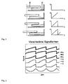
- Fig. 1 lets recognize the principle of inertial drives.
- an actuator (D) is provided which is acted upon by a sawtooth-like, periodic signal and causes an acceleration relative to a frictionally engaged with the actuator movably mounted rotor (E).
- the rotor follows the actuator due to the frictional engagement.
- the rotor slips relative to the actuator, as soon as the inertial force of the rotor is greater than the friction force between the rotor and actuator. If several steps are performed, macroscopic movements can be realized.
- Inertia drives provide a mechanically simple way to position over long distances with a high motion resolution.
- the direction of movement of the rotor can be specified.
- Inertia drives can be controlled with signals of different waveforms. It is important that a phase of high acceleration follows an opposite phase with low acceleration.
- the other waveforms B - F of Fig. 2 are typical control signals used for inertial drives.
- EP0823738 A2 shows two different waveforms.
- an object of the invention an advanced method for driving an inertial drive on the basis of eg sawtooth pulse trains with variable amplitude and / or specify variable frequency, where extremely small Sch rittweiten in the range ⁇ 5 nm can be realized and where furthermore undesirable vibrations of the system to be driven or an object coupled thereto, such as a needle-shaped object, can be minimized.
- the signal of the drive pulse sequence is changed to pulses with pulse pauses.
- the duration of the present invention shortened control pulse is so short that it is significantly less than the period of the natural oscillations of the system to be driven.
- the individual sawtooth pulse of the pulse train consists not only of a slow and a fast FK, but of a sequence of a slow edge, a fast edge and a slow edge in the sense of a shortened sawtooth pulse .
- the definition of the slow flank is to be understood such that no slippage between rotor and friction body is triggered.
- the slow edge can be shortened down to the single-digit microsecond range, or even lower.
- the duration of the control pulse according to the invention is below the period of the natural oscillation of the system to be driven, the rotor can no longer follow the sawtooth.
- a movement step is performed.
- the size of the step is less than it would result in much slower pulses of equal amplitude.
- the step acts like a spontaneous jump to a different position, so that it reacts with a typical step response, whereby the amplitude of the oscillation in this case depends almost linearly on the width of the jump itself.
- the duration of a shortening pulse can then be kept constant for further operation, the step frequency being determined by the length of the pause between the steps. However, it is not excluded to dynamically adjust the step duration to operating conditions.
- extreme forms of a sequence of slow edges and fast edges can be selected in the form of a square wave signal.
- curve shapes that are incompatible with classic stick-slip inertial drives, as a substantial movement section during the direction of movement reversal of the actuator does not result from a sequence of adhesion and slippage (stick-slip), but a series of sliding in different directions movement It is also important that the duration of the control pulse according to the invention is so short that it lies substantially below the period of the natural oscillations of the system to be driven.
- shortened control pulses can also be applied to all other waveforms suitable for inertial drives and other waveforms that exhibit a sequence of slow and fast edges.
- a pulse break is provided between the individual pulses, wherein the pulse duration is selected to be shorter than the period of the natural oscillation of the system to be driven.
- the step frequency of the drive can be determined by the variable length of the pulse pauses.
- a pulse of the pulse train preferably to be used results from a sequence with a slowly rising, rapidly falling and again slowly rising edge. If the drive is to travel in the opposite direction, then the directions of movement of the flanks must be reversed.
- Amplitude values can be adjusted accordingly to keep the step size constant. To obtain the small increments, a dynamic amplitude control is performed according to the invention.
- step size Due to the novel, linear relationship between vibration and step size, or amplitude, very small steps, down to the minimum amplitude at which steps are still performed, can now be used in a technically meaningful way. If the step size is smaller than the nominal step size, the step size can be increased by an increase in amplitude. If the step size is too large, the amplitude is reduced slightly. In the vicinity of the minimum amplitude the inertial drive is very sensitive to influences such as e.g. external forces, force variations due to manufacturing inaccuracies, etc. Therefore, a closed loop for operation near the minimum amplitudes is very advantageous.
- a fast control loop prevents the drive from locking up. If the step size is zero due to small control amplitudes, the voltage must be increased until the rotor moves again (breaks loose). If the voltage is increased slowly, the final voltage at which the drive breaks loose - the drive has seized. Consequently the drive makes a relatively large step even after breaking loose. However, if a rapid response via a control loop, so no high breakaway voltage must be overcome. This means that all step sizes up to zero can be used.
- the speed of the drive can be adjusted by means of the product of step frequency and increment, whereby areas with expected strong vibration of the system to be driven are masked out by selecting the step size.
- the first steps in the respective new direction are substantially larger in the case of a constant amplitude of the pulse train, compared to the case where the movement has already been moved in this (new) direction for a longer time.
- the step size gradually decreases, until the same step size is reached again as before the direction reversal.
- the amplitude of the control signals to be set is frequency-dependent. That is, there is a dependence on the self-resonant frequencies of the positioner, which are reflected in pronounced increases and decreases in the control amplitude, which is necessary to drive the rotor with constant pitches.
- the natural resonance frequencies are influenced by the installation or the installation position of the positioner in the overall system and vary from device to device.
- This frequency dependency can be recorded, stored and compensated for as part of a calibration procedure using a position sensor. This makes it possible to tailor the control voltages and frequencies to one another in a targeted manner, so that even without a displacement sensor integrated according to the invention, the step widths remain constant when passing through the frequencies.
- step frequency and step size are dependent on the amplitude of the driving pulse train. There are therefore different combinations of step frequency and step size to achieve the desired speed.
- control circuits either use a constant, often maximum amplitude or use different amplitudes for different speed ranges.
- step frequency and step size In order to realize desired small increments, a novel control of the step frequency and step size is provided. Here it is necessary to set the amplitude such that areas are avoided in which steps with a frequency below the resonant frequency of the positioner trigger vibrations. The amplitudes of these disturbing vibrations increase with increasing step size. However, step frequencies far above the resonant frequency of the positioner cause little vibration.
- the range of strong vibrations around in contrast to the prior art, which is based on classical control approaches, the range of strong vibrations around.
- the amplitude or also the frequency and amplitude can be increased together. It is possible to continue to use the shortened steps, but it is also possible in the fast range to common drive signals, e.g. Control signals from known inertial drives to change.
- scanning movement and step movement can be superimposed.
- the scan movement results from a quasi-static, in comparison to the edges of the step slowly variable, control.
- the overlay can be realized so that a step is performed as soon as the scan movement has reached a threshold value. After the step, the voltage applied to the actuator is again such that it can be scanned anew.
- the inventively shortened pulses for the actuation of the actuators can be applied to a single actuator which drives a runner, also called a slider.
- actuators together drive a rotor, e.g. when the runner is to be driven with a greater force than a single actuator is capable of.
- a variant would be that all actuators at the same time get the same control signals applied, another variant is a time-delayed control of the various actuators, each inventively shortened pulses.
- the last variant described has the advantage that such a positioning system allows a particularly uniform and vigorous movement of the rotor. Due to the elasticities in the individual actuators and the mechanics, it is possible to let the actuators act on the rotor in a time-delayed manner without building up too high a mechanical stress between the friction surfaces of the individual actuators and the rotor for a uniform movement.
- the drives can perform much smaller steps with low vibration than previously usual with the control signal according to the invention very short. This also makes it possible to drive slow speeds with a high cadence, if the steps are chosen small enough. So it is e.g. possible to drive a high bandwidth of speeds, the step frequency are always above the audible range. This results in noiseless driving of the drives.
- the frequency can also be reduced.
- the drives can then be controlled with very small amplitudes and, due to the short pulses of the invention, very little noise-generating vibrations occur.
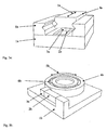
- Fig. 3a shows a simplified linear inertial drive. Shown are the typical components. These are the carrier (1a) fastened to the carrier and actuated by the saw teeth actuator (2a), and located on the actuator friction surface (3a). The friction surface (3a) is in constant frictional contact with the rotor (4a). By suitable control of the actuator (2a), the rotor can be moved along the direction (5a). In this figure, the rotor (4a) is guided by a guide (6a).
- Fig. 3b shows a simplified rotary inertial drive. Shown are the typical components. These are the carrier (1b) fastened to the carrier and actuated by the saw teeth actuator (2b), and located on the actuator friction surface (3b). The friction surface (3b) is in constant frictional contact with the rotor (4b). By suitable activation of the actuator (2b), the rotor can be moved along the direction (5b). In this figure, the rotor (4b) is guided in rotation by a bearing (6b).
- FIG. 4 shows how a friction body (dark lined) takes a runner (light line).
- a friction body dark lined
- the desired take-away of the runner takes place.
- slippage occurs between the friction body and the runner, although this does not happen completely. Rather, the runner is always pulled back with a piece.
- the distance to which the unwanted return movement takes place not only in relation to the step size, but also absolutely larger, with the result that a Reducing the step size leads to an amplification of unwanted vibrations of the driven object.
- the Fig. 5a illustrates the comparison of a traditional sawtooth pulse (dark waveform) to an exemplary inventively shortened sawtooth pulse (light waveform).
- the differences in the pulse duration are shown reduced.
- the drive signal is changed to saw teeth with break and the duration of the shortened sawtooth pulse is reduced so that it is substantially less than the period of the oscillations of the positioner.
- the pulse durations of the traditional sawtooth and the shortened sawtooth can definitely differ by several orders of magnitude.
- the Fig. 5b illustrates the comparison of a traditional parabolic signal for driving (dark waveform) to an exemplary shortened according to the invention parabolic waveform (light waveform).
- the drive signal is changed into pulses with pause and the duration of the shortened pulse is reduced so that it is substantially less than the period of the oscillations of the positioner.
- the pulse durations of the traditional waveform and the control signal shortened according to the invention may well differ by several orders of magnitude.
- Fig. 6a shows a simplified sketch A guided in the guide (5b) rotor (5a) is driven forward with a sawtooth signal to the actuators.
- a small mirror (5c) is fixed, the position of which is monitored by the laser (5d) of a laser interferometer.
- a further mirror (5f) is fastened to the rotor (5a) via a thin rod (5e). Since the rod (5e) is thin and the mirror (5f) has a relatively high mass, the mirror (5f) can be easily excited to vibrate. The movements of the mirror (5f) are monitored by a second laser beam (5g) of the laser interferometer.
- Fig. 6b shows real measurements, which were determined with the experimental setup described above.
- the runner was stimulated via saw teeth to a step of 20nm.
- the graph at the top clearly shows that the slide converts only a very small proportion of the movement made by the actuator into a step (20nm), the largest part is merely a swing of the runner in the order of magnitude of 400nm.
- the measured position is shown directly on the rotor (5a). It is a 20nm step to see. In order to assess any existing settling, the resolution of the Fig. 5b not enough, It can be clearly seen that the vibrations are much lower than with a step over a conventional sawtooth. The same applies to the oscillation of the mirror (5f), shown in the lowest graph. The 20nm step can be recognized with a subsequently very small and fast Transient response. The behavior is significantly better than when using a conventional sawtooth.
- Fig. 6c shows real measurements, which were determined with the experimental setup described above.
- the runner was stimulated via parabolic signals to a step of 100nm.
- the graph at the top clearly shows that the slide converts only a very small proportion of the movement made by the actuator into a step (100 nm), the largest part being merely a swing of the rotor on the order of several micrometers.
- the effect of the vibration of the rotor on the mirror (5f) is shown in the second graph from above.
- Here is a mirror oscillation with an amplitude of several micrometers to observe with a subsequent long settling time.
- the measured position is shown directly on the rotor (5a). It is a 100nm step to see. In order to assess any existing settling, the resolution of the Fig. 6c unsatisfactory. It can clearly be seen that the vibrations are much lower than in the case of the positioner controlled by a conventional parabolic signal. The same applies to the oscillation of the mirror (5f), shown in the lowest graph.
- the 100nm step can be recognized with a subsequent very small and fast transient response. The behavior is again significantly better than when using a conventional parabolic signal.
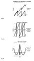
- the Fig. 7 illustrates the response of the system to be driven to an exemplary, according to the invention truncated sawtooth pulse.
- the light gray line shows the real step response compared to the mid gray line, which represents the ideal step response.
- Fig. 8 shows that the vibrations of an inertial drive, driven by a traditional control signal, become larger with decreasing step sizes (dark line), which makes the use of very small step sizes technically useless.
- Fig. 9 shows the typical behavior of an inertial drive in the range of the smallest possible step sizes - with and without amplitude control.
- the step sizes become progressively smaller until no more step is performed. If the amplitudes are then increased again, steps are not immediately carried out again, but the amplitude must be increased until the drive suddenly makes a large step. As soon as such a step has been carried out, the step size can be controlled again by varying the amplitude (black arrows).
- the step size over the amplitude can be used continuously, down to a step size of zero, in a linear relationship (black / gray arrow), because a fast control loop prevents the "stalling" described above. It does not come to the hysteresis, so that the small steps are technically useful.
- Fig. 10 It can be seen how, for an exemplary positioner, by selecting appropriate step sizes and frequencies, areas of high vibration (gray area) can be masked out.
- the black line represents a possible control curve which avoids the combinations of step frequency and step size which lead to strong vibrations.
- Fig. 11a shows three exemplary sawtooth pulses according to the invention with different symmetries.
- the uppermost (dark line) shows a symmetrical sawtooth.
- the areas enclosed by the sawtooth and the dotted line are equal above and below the mean value of the control signal.
- the asymmetry can be generated by different methods. For the middle case (dark gray), the asymmetry is set via different heights of the amplitude, while in the lowest case (light gray) an asymmetry is generated across different steep edges.
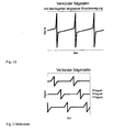
- Fig. 11b shows three exemplary rectangular pulse trains according to the invention with different symmetries.
- the uppermost (dark line) shows a symmetrical rectangular pulse train.
- the areas enclosed by the rectangular signals and the dotted line are equal above and below the mean value of the control signal.
- the asymmetry can be generated by different methods. For the middle case (dark gray), the asymmetry is set via different amplitude heights, while in the lowest case (light gray) an asymmetry over a different duration between the slip phases is generated.
- Fig. 12 shows an overlay of a scanning movement with exemplary sawtooth pulses according to the invention.
- a slowly rising line interrupted by shege leopardimpulse.
- One such Drive signal allows to perform a continuous scan movement with a runner.
- the scan movement results from a quasi-static, in comparison to the edges of the step slowly variable, control.
- the overlay can be realized so that a step is performed as soon as the scan movement has reached a threshold value. After the step, the voltage applied to the actuator is at the same level as before the first scan, so that you can rescan again. By repeating these cycles, the possible stroke is theoretically unlimited.
- Fig. 13 shows exemplary, inventively shortened sawtooth waveforms with which a drive can be controlled with in this case three actuators.
- the saw teeth are made with the same frequency, but are offset in time, so that not all actuators perform a step at the same time.
- powerful actuators can be realized with a very smooth running behavior.
Landscapes
- General Electrical Machinery Utilizing Piezoelectricity, Electrostriction Or Magnetostriction (AREA)
Claims (12)
- Procédé de commande d'un entraînement par inertie sur la base de séquences d'impulsions avec des segments de gradients différents ainsi qu'une amplitude variable et/ou une fréquence variable,
une pause d'impulsion étant prévue entre les différentes impulsions des séquences d'impulsions, la durée d'impulsion étant sélectionnée sensiblement inférieure à la durée périodique des oscillations propres du système à entraîner. - Procédé selon la revendication 1, caractérisé en ce que
chaque impulsion d'une séquence se présente avec un flanc de pente lentement ascendante, rapidement descendante et lentement ascendante, ou un flanc de pente lentement descendante, rapidement ascendante et lentement descendante. - Procédé selon la revendication 1 ou 2, caractérisé en ce que
la durée de l'impulsion est maintenue constante et la fréquence de pas de l'entraînement est déterminée par la longueur variable des pauses d'impulsion. - Procédé selon l'une des revendications précédentes, caractérisé en ce que
en cas de changement de sens de l'entraînement, les valeurs d'amplitude sont ajustées pour compenser la variation de pas. - Procédé selon l'une des revendications précédentes, caractérisé en ce que
les valeurs d'amplitude sont réajustées pour maintenir un pas constant. - Procédé selon la revendication 5, caractérisé en ce que
une régulation dynamique d'amplitude est appliquée pour obtenir des pas courts, ≤ 5 nm. - Procédé selon la revendication 6, caractérisé en ce que
la vitesse de l'entraînement est réglable par le produit de la fréquence et de la grandeur du pas, en annulant les plages où est attendue une vibration renforcée du système à entraîner. - Procédé selon l'une des revendications précédentes, caractérisé en ce que
des propriétés mécaniques et/ou électriques du système à entraîner peuvent être compensées par une asymétrie d'impulsions pour les séquences d'impulsions respectives utilisées pour la commande. - Procédé selon l'une des revendications précédentes, caractérisé en ce que
les variations de pas en fonction de la fréquence sont corrigées par ajustement des amplitudes de commande, cet ajustement pouvant être corrigé, par anticipation au moyen d'une série de mesures enregistrées ainsi que dynamiquement. - Procédé selon l'une des revendications précédentes, caractérisé en ce que
une superposition d'un mouvement de balayage lent et d'impulsions rapides permet un déplacement continu de l'entraînement. - Procédé selon l'une des revendications précédentes, caractérisé en ce que
plus d'un actionneur est mis en oeuvre par entraînement, les actionneurs pouvant en option être commandés de manière identique ou avec décalage temporel. - Procédé selon l'une des revendications précédentes, caractérisé en ce que
la durée d'impulsion d'une impulsion individuelle est inférieure à 50 µs.
Applications Claiming Priority (3)
| Application Number | Priority Date | Filing Date | Title |
|---|---|---|---|
| DE102011013814 | 2011-03-14 | ||
| DE102012202945A DE102012202945A1 (de) | 2011-03-14 | 2012-02-27 | Verfahren zur Ansteuerung eines Trägheitsantriebs |
| PCT/EP2012/053347 WO2012123251A1 (fr) | 2011-03-14 | 2012-02-28 | Procédé de commande d'un entraînement par inertie |
Publications (2)
| Publication Number | Publication Date |
|---|---|
| EP2678935A1 EP2678935A1 (fr) | 2014-01-01 |
| EP2678935B1 true EP2678935B1 (fr) | 2014-04-30 |
Family
ID=45894425
Family Applications (1)
| Application Number | Title | Priority Date | Filing Date |
|---|---|---|---|
| EP12710882.7A Active EP2678935B1 (fr) | 2011-03-14 | 2012-02-28 | Procédé de commande d'un entraînement par inertie |
Country Status (4)
| Country | Link |
|---|---|
| US (1) | US9722512B2 (fr) |
| EP (1) | EP2678935B1 (fr) |
| DE (1) | DE102012202945A1 (fr) |
| WO (1) | WO2012123251A1 (fr) |
Cited By (1)
| Publication number | Priority date | Publication date | Assignee | Title |
|---|---|---|---|---|
| DE102019115790A1 (de) * | 2019-06-11 | 2020-12-17 | Picofine GmbH | Antriebsvorrichtung und -verfahren zur linearen oder rotatorischen Positionierung |
Families Citing this family (7)
| Publication number | Priority date | Publication date | Assignee | Title |
|---|---|---|---|---|
| DE102012202945A1 (de) | 2011-03-14 | 2012-12-13 | Smaract Gmbh | Verfahren zur Ansteuerung eines Trägheitsantriebs |
| WO2012130555A1 (fr) | 2011-03-30 | 2012-10-04 | Smaract Gmbh | Procédé de pilotage d'un dispositif d'entraînement à plusieurs actionneurs |
| DE102012004401A1 (de) * | 2012-03-02 | 2013-09-05 | SmarAct Holding GmbH | Verfahren zur Ansteuerung eines Mehraktorantriebs |
| DE102012004294A1 (de) * | 2012-03-02 | 2013-09-05 | SmarAct Holding GmbH | Verfahren zur Ansteuerung eines Mehraktorantriebs |
| DE102014014997B4 (de) * | 2014-10-09 | 2018-05-17 | Attocube Systems Ag | Haft-Gleit-Antrieb, insbesondere piezo-aktuierter Trägheitsantrieb |
| CN106911264B (zh) * | 2017-04-01 | 2019-04-09 | 西安交通大学 | 轻小型单压电叠堆驱动式双向旋转惯性作动器及作动方法 |
| WO2020237116A1 (fr) * | 2019-05-22 | 2020-11-26 | Montana instruments | Entraînement de moteur piézo-électrique bipolaire à glissement-grippage |
Family Cites Families (26)
| Publication number | Priority date | Publication date | Assignee | Title |
|---|---|---|---|---|
| GB9205665D0 (en) | 1992-03-16 | 1992-04-29 | Fisons Plc | Piezo-electric motor |
| DE4237509A1 (de) * | 1992-11-06 | 1994-05-19 | Danfoss As | Verfahren und Schaltungsanordnung zum Aufladen und Entladen einer Last mit einem kapazitiven Anteil |
| FR2735923B1 (fr) | 1995-06-23 | 1997-08-29 | Suisse Electronique Microtech | Actionneur piezoelectriques de tres haute precision |
| GB2316222B (en) | 1996-08-05 | 1998-07-01 | Karrai Haines Gbr | Inertial positioner |
| US6140750A (en) | 1997-04-14 | 2000-10-31 | Minolta Co., Ltd. | Actuator using electromechanical transducer and apparatus employing the actuator |
| JPH10337056A (ja) * | 1997-06-02 | 1998-12-18 | Minolta Co Ltd | 駆動装置の制御方法 |
| JPH11103583A (ja) * | 1997-09-26 | 1999-04-13 | Minolta Co Ltd | 電気機械変換素子を使用した駆動装置及びその駆動に適した駆動パルス発生装置 |
| JPH11289780A (ja) | 1998-03-31 | 1999-10-19 | Minolta Co Ltd | 電気機械変換素子を用いた駆動装置 |
| JP4277384B2 (ja) * | 1999-09-30 | 2009-06-10 | コニカミノルタホールディングス株式会社 | 圧電アクチュエータ |
| JP2002058266A (ja) * | 2000-08-08 | 2002-02-22 | Minolta Co Ltd | 超音波駆動装置 |
| JP4154851B2 (ja) * | 2000-10-31 | 2008-09-24 | コニカミノルタホールディングス株式会社 | 駆動装置 |
| DE10148267B4 (de) | 2001-06-08 | 2005-11-24 | Physik Instrumente (Pi) Gmbh & Co. Kg | Piezolinearantrieb mit einer Gruppe von Piezostapelaktoren sowie Verfahren zum Betreiben eines solchen Antriebes |
| US7646137B2 (en) | 2004-06-11 | 2010-01-12 | Fujinon Corporation | Actuator and its control method and lens device |
| JP2006115631A (ja) * | 2004-10-15 | 2006-04-27 | Konica Minolta Holdings Inc | 圧電駆動装置 |
| US20090135683A1 (en) * | 2005-09-12 | 2009-05-28 | Osamu Mizuno | Drive mechanism and optical head |
| DE102006048238B4 (de) | 2005-11-23 | 2011-07-28 | Physik Instrumente (PI) GmbH & Co. KG, 76228 | Piezolinearantrieb |
| KR101092819B1 (ko) * | 2006-04-11 | 2011-12-12 | 코니카 미놀타 옵토 인코포레이티드 | 구동장치 |
| US7355325B2 (en) | 2006-06-15 | 2008-04-08 | Piezomotor Uppsala Ab | Wide frequency range electromechanical actuator |
| DE102008003879A1 (de) | 2007-01-25 | 2008-07-31 | Siemens Aktiengesellschaft | Linearantrieb, Antriebseinheit zur Ausbildung eines Linearantriebs sowie Verfahren zum Verschieben eines Objekts mittels eines Linearantriebs |
| EP2216837A1 (fr) | 2009-02-07 | 2010-08-11 | Physik Instrumente (PI) GmbH & Co. KG | Moteur piézoélectrique |
| KR20110130333A (ko) * | 2009-02-27 | 2011-12-05 | 히다치 막셀 가부시키가이샤 | 구동장치, 렌즈부품, 및 카메라 모듈 |
| DE102009013849A1 (de) | 2009-03-18 | 2010-09-30 | Forschungszentrum Jülich GmbH | Vorrichtung und Verfahren zur elektromechanischen Positionierung |
| WO2010113505A1 (fr) | 2009-03-31 | 2010-10-07 | 株式会社ニコン | Actuateur piézoélectrique et barillet d'objectif |
| US8593033B2 (en) | 2009-06-11 | 2013-11-26 | Micronix Usa | Multi-element, stick-slip piezo motor |
| DE102012202945A1 (de) | 2011-03-14 | 2012-12-13 | Smaract Gmbh | Verfahren zur Ansteuerung eines Trägheitsantriebs |
| WO2012130555A1 (fr) | 2011-03-30 | 2012-10-04 | Smaract Gmbh | Procédé de pilotage d'un dispositif d'entraînement à plusieurs actionneurs |
-
2012
- 2012-02-27 DE DE102012202945A patent/DE102012202945A1/de not_active Withdrawn
- 2012-02-28 WO PCT/EP2012/053347 patent/WO2012123251A1/fr active Application Filing
- 2012-02-28 US US14/005,195 patent/US9722512B2/en active Active
- 2012-02-28 EP EP12710882.7A patent/EP2678935B1/fr active Active
Cited By (3)
| Publication number | Priority date | Publication date | Assignee | Title |
|---|---|---|---|---|
| DE102019115790A1 (de) * | 2019-06-11 | 2020-12-17 | Picofine GmbH | Antriebsvorrichtung und -verfahren zur linearen oder rotatorischen Positionierung |
| EP3754834A1 (fr) | 2019-06-11 | 2020-12-23 | Picofine GmbH | Dispositif d'entraînement et procédé de positionnement linéaire ou rotatif |
| US11290030B2 (en) | 2019-06-11 | 2022-03-29 | Picofine GmbH | Drive device and method for linear or rotary positioning |
Also Published As
| Publication number | Publication date |
|---|---|
| US9722512B2 (en) | 2017-08-01 |
| EP2678935A1 (fr) | 2014-01-01 |
| US20140152147A1 (en) | 2014-06-05 |
| WO2012123251A1 (fr) | 2012-09-20 |
| DE102012202945A1 (de) | 2012-12-13 |
Similar Documents
| Publication | Publication Date | Title |
|---|---|---|
| EP2678935B1 (fr) | Procédé de commande d'un entraînement par inertie | |
| EP2692051B1 (fr) | Procédé de pilotage d'un dispositif d'entraînement à plusieurs actionneurs | |
| EP3120449B1 (fr) | Mécanisme d'entraînement par inertie | |
| DE102014225154B3 (de) | Verfahren und Vorrichtung zur Ansteuerung eines piezoelektrischen Motors | |
| EP2084758B1 (fr) | Dispositif d'entraînement par inertie | |
| DE102008003879A1 (de) | Linearantrieb, Antriebseinheit zur Ausbildung eines Linearantriebs sowie Verfahren zum Verschieben eines Objekts mittels eines Linearantriebs | |
| EP3365926B1 (fr) | Procédé de commande d'un élément électromécanique | |
| DE102016213596B4 (de) | Verfahren und Vorrichtung zur linearen und/oder rotatorischen Positionierung | |
| EP3754834A1 (fr) | Dispositif d'entraînement et procédé de positionnement linéaire ou rotatif | |
| EP2982618A1 (fr) | Convoyeur oscillant destine au mouvement bidimensionnel d'objets et procede de fonctionnement du convoyeur oscillant | |
| EP3245676B1 (fr) | Procédé et appareil de commande d'un élément électromécanique | |
| DE19806127B4 (de) | Verfahren zur elektrischen Ansteuerung von piezoelektrischen oder elektrostriktiven Aktuatoren in Antrieben für eine schrittweise Bewegung | |
| DE10012751A1 (de) | Verstellvorrichtung zum Verschieben einzelner Elemente von optischen Systemen oder von Meßsystemen | |
| DE102012221892A1 (de) | Antriebsvorrichtung und -verfahren zur linearen oder rotatorischen Positionierung | |
| DE102006029925B4 (de) | Verfahren zum Betrieb eines Stellantriebs und Stellantrieb | |
| WO2013128030A2 (fr) | Procédé de commande d'un entraînement à actionneurs multiples | |
| EP2295198B1 (fr) | Dispositif et procédé destinés à l'assemblage et/ou au traitement d'un joint à ajustement serré | |
| WO2013128032A1 (fr) | Procédé de commande d'un entraînement à actionneurs multiples | |
| DE102008001405A1 (de) | Piezoelektrische Antriebsvorrichtung, sowie Verfahren zum Betreiben einer solchen | |
| WO2009056382A1 (fr) | Dispositif d'entraînement piézoélectrique, et procédé pour le faire fonctionner | |
| DE102008041452A1 (de) | Piezoelektrische Antriebsvorrichtung sowie Ansteuerverfahren | |
| DE602005001844T2 (de) | Piezoelektrisches Antriebselement | |
| DE102011055649A1 (de) | Verfahren und Vorrichtung zur Ansteuerung piezoelektrischer Aktoren | |
| WO2023006302A1 (fr) | Procédé de commande d'unité d'entraînement piézoélectrique | |
| DE19645210A1 (de) | Verfahren und Vorrichtung zur Regelung der Lage eines reibungsbehafteten Stellers |
Legal Events
| Date | Code | Title | Description |
|---|---|---|---|
| PUAI | Public reference made under article 153(3) epc to a published international application that has entered the european phase |
Free format text: ORIGINAL CODE: 0009012 |
|
| 17P | Request for examination filed |
Effective date: 20130807 |
|
| AK | Designated contracting states |
Kind code of ref document: A1 Designated state(s): AL AT BE BG CH CY CZ DE DK EE ES FI FR GB GR HR HU IE IS IT LI LT LU LV MC MK MT NL NO PL PT RO RS SE SI SK SM TR |
|
| GRAP | Despatch of communication of intention to grant a patent |
Free format text: ORIGINAL CODE: EPIDOSNIGR1 |
|
| GRAS | Grant fee paid |
Free format text: ORIGINAL CODE: EPIDOSNIGR3 |
|
| DAX | Request for extension of the european patent (deleted) | ||
| INTG | Intention to grant announced |
Effective date: 20140225 |
|
| GRAA | (expected) grant |
Free format text: ORIGINAL CODE: 0009210 |
|
| AK | Designated contracting states |
Kind code of ref document: B1 Designated state(s): AL AT BE BG CH CY CZ DE DK EE ES FI FR GB GR HR HU IE IS IT LI LT LU LV MC MK MT NL NO PL PT RO RS SE SI SK SM TR |
|
| REG | Reference to a national code |
Ref country code: GB Ref legal event code: FG4D Free format text: NOT ENGLISH Ref country code: CH Ref legal event code: NV Representative=s name: NOVAGRAAF INTERNATIONAL SA, CH Ref country code: CH Ref legal event code: EP |
|
| REG | Reference to a national code |
Ref country code: AT Ref legal event code: REF Ref document number: 665692 Country of ref document: AT Kind code of ref document: T Effective date: 20140515 |
|
| REG | Reference to a national code |
Ref country code: IE Ref legal event code: FG4D Free format text: LANGUAGE OF EP DOCUMENT: GERMAN |
|
| REG | Reference to a national code |
Ref country code: DE Ref legal event code: R096 Ref document number: 502012000664 Country of ref document: DE Effective date: 20140612 |
|
| REG | Reference to a national code |
Ref country code: NL Ref legal event code: T3 |
|
| REG | Reference to a national code |
Ref country code: LT Ref legal event code: MG4D |
|
| PG25 | Lapsed in a contracting state [announced via postgrant information from national office to epo] |
Ref country code: BG Free format text: LAPSE BECAUSE OF FAILURE TO SUBMIT A TRANSLATION OF THE DESCRIPTION OR TO PAY THE FEE WITHIN THE PRESCRIBED TIME-LIMIT Effective date: 20140730 Ref country code: LT Free format text: LAPSE BECAUSE OF FAILURE TO SUBMIT A TRANSLATION OF THE DESCRIPTION OR TO PAY THE FEE WITHIN THE PRESCRIBED TIME-LIMIT Effective date: 20140430 Ref country code: CY Free format text: LAPSE BECAUSE OF FAILURE TO SUBMIT A TRANSLATION OF THE DESCRIPTION OR TO PAY THE FEE WITHIN THE PRESCRIBED TIME-LIMIT Effective date: 20140430 Ref country code: NO Free format text: LAPSE BECAUSE OF FAILURE TO SUBMIT A TRANSLATION OF THE DESCRIPTION OR TO PAY THE FEE WITHIN THE PRESCRIBED TIME-LIMIT Effective date: 20140730 Ref country code: IS Free format text: LAPSE BECAUSE OF FAILURE TO SUBMIT A TRANSLATION OF THE DESCRIPTION OR TO PAY THE FEE WITHIN THE PRESCRIBED TIME-LIMIT Effective date: 20140830 Ref country code: GR Free format text: LAPSE BECAUSE OF FAILURE TO SUBMIT A TRANSLATION OF THE DESCRIPTION OR TO PAY THE FEE WITHIN THE PRESCRIBED TIME-LIMIT Effective date: 20140731 Ref country code: FI Free format text: LAPSE BECAUSE OF FAILURE TO SUBMIT A TRANSLATION OF THE DESCRIPTION OR TO PAY THE FEE WITHIN THE PRESCRIBED TIME-LIMIT Effective date: 20140430 |
|
| PG25 | Lapsed in a contracting state [announced via postgrant information from national office to epo] |
Ref country code: SE Free format text: LAPSE BECAUSE OF FAILURE TO SUBMIT A TRANSLATION OF THE DESCRIPTION OR TO PAY THE FEE WITHIN THE PRESCRIBED TIME-LIMIT Effective date: 20140430 Ref country code: RS Free format text: LAPSE BECAUSE OF FAILURE TO SUBMIT A TRANSLATION OF THE DESCRIPTION OR TO PAY THE FEE WITHIN THE PRESCRIBED TIME-LIMIT Effective date: 20140430 Ref country code: PL Free format text: LAPSE BECAUSE OF FAILURE TO SUBMIT A TRANSLATION OF THE DESCRIPTION OR TO PAY THE FEE WITHIN THE PRESCRIBED TIME-LIMIT Effective date: 20140430 Ref country code: LV Free format text: LAPSE BECAUSE OF FAILURE TO SUBMIT A TRANSLATION OF THE DESCRIPTION OR TO PAY THE FEE WITHIN THE PRESCRIBED TIME-LIMIT Effective date: 20140430 Ref country code: HR Free format text: LAPSE BECAUSE OF FAILURE TO SUBMIT A TRANSLATION OF THE DESCRIPTION OR TO PAY THE FEE WITHIN THE PRESCRIBED TIME-LIMIT Effective date: 20140430 Ref country code: ES Free format text: LAPSE BECAUSE OF FAILURE TO SUBMIT A TRANSLATION OF THE DESCRIPTION OR TO PAY THE FEE WITHIN THE PRESCRIBED TIME-LIMIT Effective date: 20140430 |
|
| PG25 | Lapsed in a contracting state [announced via postgrant information from national office to epo] |
Ref country code: PT Free format text: LAPSE BECAUSE OF FAILURE TO SUBMIT A TRANSLATION OF THE DESCRIPTION OR TO PAY THE FEE WITHIN THE PRESCRIBED TIME-LIMIT Effective date: 20140901 |
|
| PG25 | Lapsed in a contracting state [announced via postgrant information from national office to epo] |
Ref country code: RO Free format text: LAPSE BECAUSE OF FAILURE TO SUBMIT A TRANSLATION OF THE DESCRIPTION OR TO PAY THE FEE WITHIN THE PRESCRIBED TIME-LIMIT Effective date: 20140430 Ref country code: DK Free format text: LAPSE BECAUSE OF FAILURE TO SUBMIT A TRANSLATION OF THE DESCRIPTION OR TO PAY THE FEE WITHIN THE PRESCRIBED TIME-LIMIT Effective date: 20140430 Ref country code: CZ Free format text: LAPSE BECAUSE OF FAILURE TO SUBMIT A TRANSLATION OF THE DESCRIPTION OR TO PAY THE FEE WITHIN THE PRESCRIBED TIME-LIMIT Effective date: 20140430 Ref country code: SK Free format text: LAPSE BECAUSE OF FAILURE TO SUBMIT A TRANSLATION OF THE DESCRIPTION OR TO PAY THE FEE WITHIN THE PRESCRIBED TIME-LIMIT Effective date: 20140430 Ref country code: EE Free format text: LAPSE BECAUSE OF FAILURE TO SUBMIT A TRANSLATION OF THE DESCRIPTION OR TO PAY THE FEE WITHIN THE PRESCRIBED TIME-LIMIT Effective date: 20140430 |
|
| REG | Reference to a national code |
Ref country code: DE Ref legal event code: R097 Ref document number: 502012000664 Country of ref document: DE |
|
| PLBE | No opposition filed within time limit |
Free format text: ORIGINAL CODE: 0009261 |
|
| STAA | Information on the status of an ep patent application or granted ep patent |
Free format text: STATUS: NO OPPOSITION FILED WITHIN TIME LIMIT |
|
| PG25 | Lapsed in a contracting state [announced via postgrant information from national office to epo] |
Ref country code: IT Free format text: LAPSE BECAUSE OF FAILURE TO SUBMIT A TRANSLATION OF THE DESCRIPTION OR TO PAY THE FEE WITHIN THE PRESCRIBED TIME-LIMIT Effective date: 20140430 |
|
| 26N | No opposition filed |
Effective date: 20150202 |
|
| REG | Reference to a national code |
Ref country code: DE Ref legal event code: R097 Ref document number: 502012000664 Country of ref document: DE Effective date: 20150202 |
|
| PG25 | Lapsed in a contracting state [announced via postgrant information from national office to epo] |
Ref country code: SI Free format text: LAPSE BECAUSE OF FAILURE TO SUBMIT A TRANSLATION OF THE DESCRIPTION OR TO PAY THE FEE WITHIN THE PRESCRIBED TIME-LIMIT Effective date: 20140430 |
|
| PG25 | Lapsed in a contracting state [announced via postgrant information from national office to epo] |
Ref country code: LU Free format text: LAPSE BECAUSE OF FAILURE TO SUBMIT A TRANSLATION OF THE DESCRIPTION OR TO PAY THE FEE WITHIN THE PRESCRIBED TIME-LIMIT Effective date: 20150228 |
|
| PG25 | Lapsed in a contracting state [announced via postgrant information from national office to epo] |
Ref country code: MC Free format text: LAPSE BECAUSE OF FAILURE TO SUBMIT A TRANSLATION OF THE DESCRIPTION OR TO PAY THE FEE WITHIN THE PRESCRIBED TIME-LIMIT Effective date: 20140430 |
|
| REG | Reference to a national code |
Ref country code: IE Ref legal event code: MM4A |
|
| PG25 | Lapsed in a contracting state [announced via postgrant information from national office to epo] |
Ref country code: IE Free format text: LAPSE BECAUSE OF NON-PAYMENT OF DUE FEES Effective date: 20150228 |
|
| REG | Reference to a national code |
Ref country code: FR Ref legal event code: PLFP Year of fee payment: 5 |
|
| GBPC | Gb: european patent ceased through non-payment of renewal fee |
Effective date: 20160228 |
|
| PG25 | Lapsed in a contracting state [announced via postgrant information from national office to epo] |
Ref country code: MT Free format text: LAPSE BECAUSE OF FAILURE TO SUBMIT A TRANSLATION OF THE DESCRIPTION OR TO PAY THE FEE WITHIN THE PRESCRIBED TIME-LIMIT Effective date: 20140430 |
|
| PG25 | Lapsed in a contracting state [announced via postgrant information from national office to epo] |
Ref country code: GB Free format text: LAPSE BECAUSE OF NON-PAYMENT OF DUE FEES Effective date: 20160228 |
|
| REG | Reference to a national code |
Ref country code: FR Ref legal event code: PLFP Year of fee payment: 6 |
|
| PG25 | Lapsed in a contracting state [announced via postgrant information from national office to epo] |
Ref country code: SM Free format text: LAPSE BECAUSE OF FAILURE TO SUBMIT A TRANSLATION OF THE DESCRIPTION OR TO PAY THE FEE WITHIN THE PRESCRIBED TIME-LIMIT Effective date: 20140430 Ref country code: HU Free format text: LAPSE BECAUSE OF FAILURE TO SUBMIT A TRANSLATION OF THE DESCRIPTION OR TO PAY THE FEE WITHIN THE PRESCRIBED TIME-LIMIT; INVALID AB INITIO Effective date: 20120228 |
|
| PG25 | Lapsed in a contracting state [announced via postgrant information from national office to epo] |
Ref country code: TR Free format text: LAPSE BECAUSE OF FAILURE TO SUBMIT A TRANSLATION OF THE DESCRIPTION OR TO PAY THE FEE WITHIN THE PRESCRIBED TIME-LIMIT Effective date: 20140430 |
|
| REG | Reference to a national code |
Ref country code: FR Ref legal event code: PLFP Year of fee payment: 7 |
|
| REG | Reference to a national code |
Ref country code: AT Ref legal event code: MM01 Ref document number: 665692 Country of ref document: AT Kind code of ref document: T Effective date: 20170228 |
|
| PG25 | Lapsed in a contracting state [announced via postgrant information from national office to epo] |
Ref country code: AT Free format text: LAPSE BECAUSE OF NON-PAYMENT OF DUE FEES Effective date: 20170228 |
|
| PG25 | Lapsed in a contracting state [announced via postgrant information from national office to epo] |
Ref country code: MK Free format text: LAPSE BECAUSE OF FAILURE TO SUBMIT A TRANSLATION OF THE DESCRIPTION OR TO PAY THE FEE WITHIN THE PRESCRIBED TIME-LIMIT Effective date: 20140430 |
|
| PG25 | Lapsed in a contracting state [announced via postgrant information from national office to epo] |
Ref country code: AL Free format text: LAPSE BECAUSE OF FAILURE TO SUBMIT A TRANSLATION OF THE DESCRIPTION OR TO PAY THE FEE WITHIN THE PRESCRIBED TIME-LIMIT Effective date: 20140430 |
|
| PGFP | Annual fee paid to national office [announced via postgrant information from national office to epo] |
Ref country code: FR Payment date: 20230220 Year of fee payment: 12 |
|
| PGFP | Annual fee paid to national office [announced via postgrant information from national office to epo] |
Ref country code: BE Payment date: 20230220 Year of fee payment: 12 |
|
| PGFP | Annual fee paid to national office [announced via postgrant information from national office to epo] |
Ref country code: NL Payment date: 20240220 Year of fee payment: 13 |
|
| PGFP | Annual fee paid to national office [announced via postgrant information from national office to epo] |
Ref country code: DE Payment date: 20240312 Year of fee payment: 13 Ref country code: CH Payment date: 20240301 Year of fee payment: 13 |