EP2678935B1 - Method for controlling an inertial drive - Google Patents
Method for controlling an inertial drive Download PDFInfo
- Publication number
- EP2678935B1 EP2678935B1 EP12710882.7A EP12710882A EP2678935B1 EP 2678935 B1 EP2678935 B1 EP 2678935B1 EP 12710882 A EP12710882 A EP 12710882A EP 2678935 B1 EP2678935 B1 EP 2678935B1
- Authority
- EP
- European Patent Office
- Prior art keywords
- pulse
- drive
- amplitude
- frequency
- sawtooth
- Prior art date
- Legal status (The legal status is an assumption and is not a legal conclusion. Google has not performed a legal analysis and makes no representation as to the accuracy of the status listed.)
- Active
Links
- 238000000034 method Methods 0.000 title claims description 18
- 230000033001 locomotion Effects 0.000 claims description 34
- 230000010355 oscillation Effects 0.000 claims description 15
- 230000000630 rising effect Effects 0.000 claims description 7
- 230000001419 dependent effect Effects 0.000 claims description 5
- 238000005259 measurement Methods 0.000 claims description 4
- 230000004044 response Effects 0.000 description 10
- 238000001208 nuclear magnetic resonance pulse sequence Methods 0.000 description 9
- 230000001133 acceleration Effects 0.000 description 8
- 230000000052 comparative effect Effects 0.000 description 8
- 230000000694 effects Effects 0.000 description 7
- 230000007423 decrease Effects 0.000 description 3
- 230000003247 decreasing effect Effects 0.000 description 3
- 238000010586 diagram Methods 0.000 description 3
- 230000001960 triggered effect Effects 0.000 description 3
- 230000003321 amplification Effects 0.000 description 2
- 238000013459 approach Methods 0.000 description 2
- 230000008859 change Effects 0.000 description 2
- 238000009434 installation Methods 0.000 description 2
- 239000000463 material Substances 0.000 description 2
- 238000003199 nucleic acid amplification method Methods 0.000 description 2
- 230000000737 periodic effect Effects 0.000 description 2
- 230000001052 transient effect Effects 0.000 description 2
- 230000004913 activation Effects 0.000 description 1
- 230000000454 anti-cipatory effect Effects 0.000 description 1
- 238000010009 beating Methods 0.000 description 1
- 230000008901 benefit Effects 0.000 description 1
- 238000010276 construction Methods 0.000 description 1
- 238000011161 development Methods 0.000 description 1
- 230000018109 developmental process Effects 0.000 description 1
- 238000006073 displacement reaction Methods 0.000 description 1
- 238000005516 engineering process Methods 0.000 description 1
- 230000002452 interceptive effect Effects 0.000 description 1
- 238000004519 manufacturing process Methods 0.000 description 1
- 239000011295 pitch Substances 0.000 description 1
- 230000009467 reduction Effects 0.000 description 1
- 238000004904 shortening Methods 0.000 description 1
- 230000002269 spontaneous effect Effects 0.000 description 1
- 230000003068 static effect Effects 0.000 description 1
Images


Classifications
-
- H—ELECTRICITY
- H02—GENERATION; CONVERSION OR DISTRIBUTION OF ELECTRIC POWER
- H02N—ELECTRIC MACHINES NOT OTHERWISE PROVIDED FOR
- H02N2/00—Electric machines in general using piezoelectric effect, electrostriction or magnetostriction
- H02N2/02—Electric machines in general using piezoelectric effect, electrostriction or magnetostriction producing linear motion, e.g. actuators; Linear positioners ; Linear motors
- H02N2/06—Drive circuits; Control arrangements or methods
- H02N2/065—Large signal circuits, e.g. final stages
- H02N2/067—Large signal circuits, e.g. final stages generating drive pulses
-
- H—ELECTRICITY
- H02—GENERATION; CONVERSION OR DISTRIBUTION OF ELECTRIC POWER
- H02N—ELECTRIC MACHINES NOT OTHERWISE PROVIDED FOR
- H02N2/00—Electric machines in general using piezoelectric effect, electrostriction or magnetostriction
- H02N2/02—Electric machines in general using piezoelectric effect, electrostriction or magnetostriction producing linear motion, e.g. actuators; Linear positioners ; Linear motors
- H02N2/021—Electric machines in general using piezoelectric effect, electrostriction or magnetostriction producing linear motion, e.g. actuators; Linear positioners ; Linear motors using intermittent driving, e.g. step motors, piezoleg motors
- H02N2/025—Inertial sliding motors
-
- H—ELECTRICITY
- H02—GENERATION; CONVERSION OR DISTRIBUTION OF ELECTRIC POWER
- H02N—ELECTRIC MACHINES NOT OTHERWISE PROVIDED FOR
- H02N2/00—Electric machines in general using piezoelectric effect, electrostriction or magnetostriction
- H02N2/10—Electric machines in general using piezoelectric effect, electrostriction or magnetostriction producing rotary motion, e.g. rotary motors
- H02N2/101—Electric machines in general using piezoelectric effect, electrostriction or magnetostriction producing rotary motion, e.g. rotary motors using intermittent driving, e.g. step motors
Definitions
- the invention relates to a method for controlling an inertial drive on the basis of pulse sequences with variable amplitude and / or variable frequency according to claim 1.
- inertial drives e.g. To supply piezo-slip-stick drives with electrical signals which have a flat as well as a steep flank in the manner of a sawtooth voltage.
- the distance to be moved back is not only increased in relation to the step size, but also completely larger, with the result that a reduction of the step size leads to an amplification of unwanted vibrations of the drive.
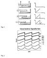
- Fig. 1 lets recognize the principle of inertial drives.
- an actuator (D) is provided which is acted upon by a sawtooth-like, periodic signal and causes an acceleration relative to a frictionally engaged with the actuator movably mounted rotor (E).
- the rotor follows the actuator due to the frictional engagement.
- the rotor slips relative to the actuator, as soon as the inertial force of the rotor is greater than the friction force between the rotor and actuator. If several steps are performed, macroscopic movements can be realized.
- Inertia drives provide a mechanically simple way to position over long distances with a high motion resolution.
- the direction of movement of the rotor can be specified.
- Inertia drives can be controlled with signals of different waveforms. It is important that a phase of high acceleration follows an opposite phase with low acceleration.
- the other waveforms B - F of Fig. 2 are typical control signals used for inertial drives.
- EP0823738 A2 shows two different waveforms.
- an object of the invention an advanced method for driving an inertial drive on the basis of eg sawtooth pulse trains with variable amplitude and / or specify variable frequency, where extremely small Sch rittweiten in the range ⁇ 5 nm can be realized and where furthermore undesirable vibrations of the system to be driven or an object coupled thereto, such as a needle-shaped object, can be minimized.
- the signal of the drive pulse sequence is changed to pulses with pulse pauses.
- the duration of the present invention shortened control pulse is so short that it is significantly less than the period of the natural oscillations of the system to be driven.
- the individual sawtooth pulse of the pulse train consists not only of a slow and a fast FK, but of a sequence of a slow edge, a fast edge and a slow edge in the sense of a shortened sawtooth pulse .
- the definition of the slow flank is to be understood such that no slippage between rotor and friction body is triggered.
- the slow edge can be shortened down to the single-digit microsecond range, or even lower.
- the duration of the control pulse according to the invention is below the period of the natural oscillation of the system to be driven, the rotor can no longer follow the sawtooth.
- a movement step is performed.
- the size of the step is less than it would result in much slower pulses of equal amplitude.
- the step acts like a spontaneous jump to a different position, so that it reacts with a typical step response, whereby the amplitude of the oscillation in this case depends almost linearly on the width of the jump itself.
- the duration of a shortening pulse can then be kept constant for further operation, the step frequency being determined by the length of the pause between the steps. However, it is not excluded to dynamically adjust the step duration to operating conditions.
- extreme forms of a sequence of slow edges and fast edges can be selected in the form of a square wave signal.
- curve shapes that are incompatible with classic stick-slip inertial drives, as a substantial movement section during the direction of movement reversal of the actuator does not result from a sequence of adhesion and slippage (stick-slip), but a series of sliding in different directions movement It is also important that the duration of the control pulse according to the invention is so short that it lies substantially below the period of the natural oscillations of the system to be driven.
- shortened control pulses can also be applied to all other waveforms suitable for inertial drives and other waveforms that exhibit a sequence of slow and fast edges.
- a pulse break is provided between the individual pulses, wherein the pulse duration is selected to be shorter than the period of the natural oscillation of the system to be driven.
- the step frequency of the drive can be determined by the variable length of the pulse pauses.
- a pulse of the pulse train preferably to be used results from a sequence with a slowly rising, rapidly falling and again slowly rising edge. If the drive is to travel in the opposite direction, then the directions of movement of the flanks must be reversed.
- Amplitude values can be adjusted accordingly to keep the step size constant. To obtain the small increments, a dynamic amplitude control is performed according to the invention.
- step size Due to the novel, linear relationship between vibration and step size, or amplitude, very small steps, down to the minimum amplitude at which steps are still performed, can now be used in a technically meaningful way. If the step size is smaller than the nominal step size, the step size can be increased by an increase in amplitude. If the step size is too large, the amplitude is reduced slightly. In the vicinity of the minimum amplitude the inertial drive is very sensitive to influences such as e.g. external forces, force variations due to manufacturing inaccuracies, etc. Therefore, a closed loop for operation near the minimum amplitudes is very advantageous.
- a fast control loop prevents the drive from locking up. If the step size is zero due to small control amplitudes, the voltage must be increased until the rotor moves again (breaks loose). If the voltage is increased slowly, the final voltage at which the drive breaks loose - the drive has seized. Consequently the drive makes a relatively large step even after breaking loose. However, if a rapid response via a control loop, so no high breakaway voltage must be overcome. This means that all step sizes up to zero can be used.
- the speed of the drive can be adjusted by means of the product of step frequency and increment, whereby areas with expected strong vibration of the system to be driven are masked out by selecting the step size.
- the first steps in the respective new direction are substantially larger in the case of a constant amplitude of the pulse train, compared to the case where the movement has already been moved in this (new) direction for a longer time.
- the step size gradually decreases, until the same step size is reached again as before the direction reversal.
- the amplitude of the control signals to be set is frequency-dependent. That is, there is a dependence on the self-resonant frequencies of the positioner, which are reflected in pronounced increases and decreases in the control amplitude, which is necessary to drive the rotor with constant pitches.
- the natural resonance frequencies are influenced by the installation or the installation position of the positioner in the overall system and vary from device to device.
- This frequency dependency can be recorded, stored and compensated for as part of a calibration procedure using a position sensor. This makes it possible to tailor the control voltages and frequencies to one another in a targeted manner, so that even without a displacement sensor integrated according to the invention, the step widths remain constant when passing through the frequencies.
- step frequency and step size are dependent on the amplitude of the driving pulse train. There are therefore different combinations of step frequency and step size to achieve the desired speed.
- control circuits either use a constant, often maximum amplitude or use different amplitudes for different speed ranges.
- step frequency and step size In order to realize desired small increments, a novel control of the step frequency and step size is provided. Here it is necessary to set the amplitude such that areas are avoided in which steps with a frequency below the resonant frequency of the positioner trigger vibrations. The amplitudes of these disturbing vibrations increase with increasing step size. However, step frequencies far above the resonant frequency of the positioner cause little vibration.
- the range of strong vibrations around in contrast to the prior art, which is based on classical control approaches, the range of strong vibrations around.
- the amplitude or also the frequency and amplitude can be increased together. It is possible to continue to use the shortened steps, but it is also possible in the fast range to common drive signals, e.g. Control signals from known inertial drives to change.
- scanning movement and step movement can be superimposed.
- the scan movement results from a quasi-static, in comparison to the edges of the step slowly variable, control.
- the overlay can be realized so that a step is performed as soon as the scan movement has reached a threshold value. After the step, the voltage applied to the actuator is again such that it can be scanned anew.
- the inventively shortened pulses for the actuation of the actuators can be applied to a single actuator which drives a runner, also called a slider.
- actuators together drive a rotor, e.g. when the runner is to be driven with a greater force than a single actuator is capable of.
- a variant would be that all actuators at the same time get the same control signals applied, another variant is a time-delayed control of the various actuators, each inventively shortened pulses.
- the last variant described has the advantage that such a positioning system allows a particularly uniform and vigorous movement of the rotor. Due to the elasticities in the individual actuators and the mechanics, it is possible to let the actuators act on the rotor in a time-delayed manner without building up too high a mechanical stress between the friction surfaces of the individual actuators and the rotor for a uniform movement.
- the drives can perform much smaller steps with low vibration than previously usual with the control signal according to the invention very short. This also makes it possible to drive slow speeds with a high cadence, if the steps are chosen small enough. So it is e.g. possible to drive a high bandwidth of speeds, the step frequency are always above the audible range. This results in noiseless driving of the drives.
- the frequency can also be reduced.
- the drives can then be controlled with very small amplitudes and, due to the short pulses of the invention, very little noise-generating vibrations occur.
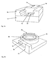
- Fig. 3a shows a simplified linear inertial drive. Shown are the typical components. These are the carrier (1a) fastened to the carrier and actuated by the saw teeth actuator (2a), and located on the actuator friction surface (3a). The friction surface (3a) is in constant frictional contact with the rotor (4a). By suitable control of the actuator (2a), the rotor can be moved along the direction (5a). In this figure, the rotor (4a) is guided by a guide (6a).
- Fig. 3b shows a simplified rotary inertial drive. Shown are the typical components. These are the carrier (1b) fastened to the carrier and actuated by the saw teeth actuator (2b), and located on the actuator friction surface (3b). The friction surface (3b) is in constant frictional contact with the rotor (4b). By suitable activation of the actuator (2b), the rotor can be moved along the direction (5b). In this figure, the rotor (4b) is guided in rotation by a bearing (6b).
- FIG. 4 shows how a friction body (dark lined) takes a runner (light line).
- a friction body dark lined
- the desired take-away of the runner takes place.
- slippage occurs between the friction body and the runner, although this does not happen completely. Rather, the runner is always pulled back with a piece.
- the distance to which the unwanted return movement takes place not only in relation to the step size, but also absolutely larger, with the result that a Reducing the step size leads to an amplification of unwanted vibrations of the driven object.
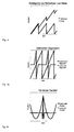
- the Fig. 5a illustrates the comparison of a traditional sawtooth pulse (dark waveform) to an exemplary inventively shortened sawtooth pulse (light waveform).
- the differences in the pulse duration are shown reduced.
- the drive signal is changed to saw teeth with break and the duration of the shortened sawtooth pulse is reduced so that it is substantially less than the period of the oscillations of the positioner.
- the pulse durations of the traditional sawtooth and the shortened sawtooth can definitely differ by several orders of magnitude.
- the Fig. 5b illustrates the comparison of a traditional parabolic signal for driving (dark waveform) to an exemplary shortened according to the invention parabolic waveform (light waveform).
- the drive signal is changed into pulses with pause and the duration of the shortened pulse is reduced so that it is substantially less than the period of the oscillations of the positioner.
- the pulse durations of the traditional waveform and the control signal shortened according to the invention may well differ by several orders of magnitude.
- Fig. 6a shows a simplified sketch A guided in the guide (5b) rotor (5a) is driven forward with a sawtooth signal to the actuators.
- a small mirror (5c) is fixed, the position of which is monitored by the laser (5d) of a laser interferometer.
- a further mirror (5f) is fastened to the rotor (5a) via a thin rod (5e). Since the rod (5e) is thin and the mirror (5f) has a relatively high mass, the mirror (5f) can be easily excited to vibrate. The movements of the mirror (5f) are monitored by a second laser beam (5g) of the laser interferometer.
- Fig. 6b shows real measurements, which were determined with the experimental setup described above.
- the runner was stimulated via saw teeth to a step of 20nm.
- the graph at the top clearly shows that the slide converts only a very small proportion of the movement made by the actuator into a step (20nm), the largest part is merely a swing of the runner in the order of magnitude of 400nm.
- the measured position is shown directly on the rotor (5a). It is a 20nm step to see. In order to assess any existing settling, the resolution of the Fig. 5b not enough, It can be clearly seen that the vibrations are much lower than with a step over a conventional sawtooth. The same applies to the oscillation of the mirror (5f), shown in the lowest graph. The 20nm step can be recognized with a subsequently very small and fast Transient response. The behavior is significantly better than when using a conventional sawtooth.
- Fig. 6c shows real measurements, which were determined with the experimental setup described above.
- the runner was stimulated via parabolic signals to a step of 100nm.
- the graph at the top clearly shows that the slide converts only a very small proportion of the movement made by the actuator into a step (100 nm), the largest part being merely a swing of the rotor on the order of several micrometers.
- the effect of the vibration of the rotor on the mirror (5f) is shown in the second graph from above.
- Here is a mirror oscillation with an amplitude of several micrometers to observe with a subsequent long settling time.
- the measured position is shown directly on the rotor (5a). It is a 100nm step to see. In order to assess any existing settling, the resolution of the Fig. 6c unsatisfactory. It can clearly be seen that the vibrations are much lower than in the case of the positioner controlled by a conventional parabolic signal. The same applies to the oscillation of the mirror (5f), shown in the lowest graph.
- the 100nm step can be recognized with a subsequent very small and fast transient response. The behavior is again significantly better than when using a conventional parabolic signal.
- the Fig. 7 illustrates the response of the system to be driven to an exemplary, according to the invention truncated sawtooth pulse.
- the light gray line shows the real step response compared to the mid gray line, which represents the ideal step response.
- Fig. 8 shows that the vibrations of an inertial drive, driven by a traditional control signal, become larger with decreasing step sizes (dark line), which makes the use of very small step sizes technically useless.
- Fig. 9 shows the typical behavior of an inertial drive in the range of the smallest possible step sizes - with and without amplitude control.
- the step sizes become progressively smaller until no more step is performed. If the amplitudes are then increased again, steps are not immediately carried out again, but the amplitude must be increased until the drive suddenly makes a large step. As soon as such a step has been carried out, the step size can be controlled again by varying the amplitude (black arrows).
- the step size over the amplitude can be used continuously, down to a step size of zero, in a linear relationship (black / gray arrow), because a fast control loop prevents the "stalling" described above. It does not come to the hysteresis, so that the small steps are technically useful.
- Fig. 10 It can be seen how, for an exemplary positioner, by selecting appropriate step sizes and frequencies, areas of high vibration (gray area) can be masked out.
- the black line represents a possible control curve which avoids the combinations of step frequency and step size which lead to strong vibrations.
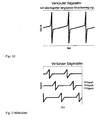
- Fig. 11a shows three exemplary sawtooth pulses according to the invention with different symmetries.
- the uppermost (dark line) shows a symmetrical sawtooth.
- the areas enclosed by the sawtooth and the dotted line are equal above and below the mean value of the control signal.
- the asymmetry can be generated by different methods. For the middle case (dark gray), the asymmetry is set via different heights of the amplitude, while in the lowest case (light gray) an asymmetry is generated across different steep edges.
- Fig. 11b shows three exemplary rectangular pulse trains according to the invention with different symmetries.
- the uppermost (dark line) shows a symmetrical rectangular pulse train.
- the areas enclosed by the rectangular signals and the dotted line are equal above and below the mean value of the control signal.
- the asymmetry can be generated by different methods. For the middle case (dark gray), the asymmetry is set via different amplitude heights, while in the lowest case (light gray) an asymmetry over a different duration between the slip phases is generated.
- Fig. 12 shows an overlay of a scanning movement with exemplary sawtooth pulses according to the invention.
- a slowly rising line interrupted by shege leopardimpulse.
- One such Drive signal allows to perform a continuous scan movement with a runner.
- the scan movement results from a quasi-static, in comparison to the edges of the step slowly variable, control.
- the overlay can be realized so that a step is performed as soon as the scan movement has reached a threshold value. After the step, the voltage applied to the actuator is at the same level as before the first scan, so that you can rescan again. By repeating these cycles, the possible stroke is theoretically unlimited.
- Fig. 13 shows exemplary, inventively shortened sawtooth waveforms with which a drive can be controlled with in this case three actuators.
- the saw teeth are made with the same frequency, but are offset in time, so that not all actuators perform a step at the same time.
- powerful actuators can be realized with a very smooth running behavior.
Description
Die Erfindung betrifft ein Verfahren zur Ansteuerung eines Trägheitsantriebs auf der Basis von Impulsfolgen mit variabler Amplitude und/oder variabler Frequenz gemäß Patentanspruch 1.The invention relates to a method for controlling an inertial drive on the basis of pulse sequences with variable amplitude and / or variable frequency according to
Es ist bekannt, Trägheitsantriebe, z.B. Piezo-Slip-Stick-Antriebe mit elektrischen Signalen zu versorgen, welche nach Art einer Sägezahnspannung eine flache sowie eine steile Flanke besitzen.It is known to use inertial drives, e.g. To supply piezo-slip-stick drives with electrical signals which have a flat as well as a steep flank in the manner of a sawtooth voltage.
Beim Anliegen der flachen Flanke nimmt der Reibkörper des Antriebs den sogenannten Slider mit. Ist die steile Flanke aktiv, kommt es zu einem Durchrutschen zwischen Reibkörper und Slider. Bei der nächsten flachen Flanke der Impulsfolge wird wiederum der Reibköper in die Lage versetzt, den Slider bewegungsmäßig mitzunehmen.When concerns the flat edge of the friction body of the drive takes the so-called slider. If the steep flank is active, slippage occurs between the friction body and the slider. On the next flat flank of the pulse sequence, the friction element is in turn enabled to move the slider in terms of movement.
Es hat sich gezeigt, dass das gewünschte Durchrutschen zwischen Reibkörper und Slider nie vollständig gelingt. So wird der Slider immer ein Stück des Weges mit zurückgenommen, wobei die Größe dieses Stückes von der Kraft des Aktors, der Masse des Sliders sowie Elastizitäten im Material und äußeren Kräften abhängt.It has been shown that the desired slipping between friction body and slider never completely succeed. Thus, the slider is always taken back a piece of the way with, the size of this piece depends on the force of the actuator, the mass of the slider as well as elasticities in the material and external forces.
Bei sehr kleinen Schritten wird die Wegstrecke, um die zurückbewegt wird, nicht nur in Relation zur Schrittgröße, sondern auch absolut größer, was zur Folge hat, dass eine Reduzierung der Schrittgröße zu einer Verstärkung unerwünschter Vibrationen des Antriebs führt.At very small steps, the distance to be moved back is not only increased in relation to the step size, but also completely larger, with the result that a reduction of the step size leads to an amplification of unwanted vibrations of the drive.
Bei kleinen Amplituden der Sägezahnspannung ist die Rückwärtsbewegung bei der steilen Flanke sehr viel größer als der durchgeführte Schritt selbst. Sinkt die Amplitude unter einen Minimalwert, werden überhaupt keine verwertbaren Schritte des anzutreibenden Systems durchgeführt.For small amplitudes of the sawtooth voltage, the backward movement at the steep edge is much greater than the step itself. If the amplitude falls below a minimum value, no actionable steps of the system to be driven are carried out at all.
Demnach wird bei der Ansteuerung eines Slip-Stick-Antriebs mit einer üblichen bekannten Sägezahnspannung die Vibrationsamplitude bei kleinen Schrittweiten nicht von der Schrittweite selbst, sondern von der Weite des Zurückrutschens an der steilen Flanke des Impulses dominiert.Accordingly, in the control of a slip-stick drive with a conventional known sawtooth voltage, the amplitude of vibration at small increments not dominated by the step itself, but by the amount of slipping back on the steep edge of the pulse.
Über die Richtung des Sägezahns kann die Bewegungsrichtung des Läufers vorgegeben werden.About the direction of the sawtooth, the direction of movement of the rotor can be specified.
Diese Antriebe haben den Nachteil, dass es aufgrund der Schritte immer wieder zu Vibrationen kommt, die für Präzisionsaufgaben stören sind.These drives have the disadvantage that due to the steps again and again comes to vibrations that are interfering with precision tasks.
Trägheitsantriebe können mit Signalen verschiedener Kurvenformen angesteuert werden. Wichtig ist es, dass einer Phase hoher Beschleunigung eine entgegengesetzte Phase mit geringer Beschleunigung folgt.Inertia drives can be controlled with signals of different waveforms. It is important that a phase of high acceleration follows an opposite phase with low acceleration.
Eine sehr übliche Kurvenform ist in
Die weiteren Kurvenformen B - F der
Weitere Antriebe und Signal sind aus
Allen bekannten Ansteuersignalen ist gemein, dass sie beim Bewegen eines Objektes störende Vibrationen einkoppeln. Mit den bekannten Steuersignalen erzeugen auch kleine Schritte große Vibrationen.All known control signals have in common that they couple disturbing vibrations when moving an object. With the well-known control signals even small steps generate large vibrations.
Aus dem Vorgenannten ist es daher Aufgabe der Erfindung, ein weiterentwickeltes Verfahren zur Ansteuerung eines Trägheitsantriebs auf der Basis von z.B. sägezahnförmigen Impulsfolgen mit variabler Amplitude und/oder variabler Frequenz anzugeben, wobei äußerst kleine Sch-rittweiten im Bereich ≤5 nm realisiert werden können und wobei weiterhin unerwünschte Vibrationen des anzutreibenden Systems bzw. eines daran angekoppelten Objekts, z.B. eines nadelförmigen Objekts, minimierbar sind.From the above, it is therefore an object of the invention, an advanced method for driving an inertial drive on the basis of eg sawtooth pulse trains with variable amplitude and / or specify variable frequency, where extremely small Sch rittweiten in the range ≤5 nm can be realized and where furthermore undesirable vibrations of the system to be driven or an object coupled thereto, such as a needle-shaped object, can be minimized.
Die Lösung der Aufgabe der Erfindung erfolgt durch die Lehre gemäß Definition nach Patentanspruch 1, wobei die Unteransprüche mindestens zweckmäßige Ausgestaltungen und Weiterbildungen darstellen.The object of the invention is achieved by the teaching according to the definition according to
Grundsätzlich wird erfindungsgemäß zur Reduzierung der Vibrationsamplitude das Signal der Ansteuerimpulsfolge zu Impulsen mit Impulspausen verändert.In principle, according to the invention, in order to reduce the vibration amplitude, the signal of the drive pulse sequence is changed to pulses with pulse pauses.
Während der Impulspausen muss nicht zwangsweise ein unveränderliches Signal anliegen. So ist es z.B. durchaus möglich, ein kontinuierlich veränderliches Signal anzulegen, um eine kontinuierliche Bewegung des Antriebs zu erzielen. Es ist auch möglich, situationsabhängige Kurven anzulegen, so dass während der Pulsdauer gewünschte Bewegungen erzielt werden können.There must not necessarily be an immutable signal during the pulse pauses. So it is e.g. quite possible to apply a continuously variable signal to achieve a continuous movement of the drive. It is also possible to create situation-dependent curves, so that desired movements can be achieved during the pulse duration.
Die Dauer des erfindungsgemäß verkürzten Steuerimpulses ist so kurz, dass sie wesentlich unter der Periodendauer der Eigenschwingungen des anzutreibenden Systems liegt.The duration of the present invention shortened control pulse is so short that it is significantly less than the period of the natural oscillations of the system to be driven.
Werden zum Beispiel angelehnt an klassische für Trägheitsantriebe verwendete Sägezahnsignale zur Ansteuerung herangezogen, besteht der einzelne Sägezahnimpuls der Impulsfolge nicht nur aus einer langsamen und einer schnellen Fklanke, sondern aus einer Folge einer langsamen Flanke, einer schnellen Flanke und einer langsamen Flanke im Sinne eines verkürzten Sägezahnimpulses. Die Definition der langsamen Flanke ist so zu verstehen, dass kein Durchrutschen zwischen Läufer und Reibkörper ausgelöst wird. Dabei kann die langsame Flanke bis in den einstelligen Mikrosekundenbereich hinein, oder sogar darunter, verkürzt werden.If, for example, based on classical sawtooth signals used for inertial drives, the individual sawtooth pulse of the pulse train consists not only of a slow and a fast FK, but of a sequence of a slow edge, a fast edge and a slow edge in the sense of a shortened sawtooth pulse , The definition of the slow flank is to be understood such that no slippage between rotor and friction body is triggered. The slow edge can be shortened down to the single-digit microsecond range, or even lower.
Da die Dauer des erfindungsgemäßen Steuerimpulses unter der Periodendauer der Eigenschwingung des anzutreibenden Systems liegt, kann der Läufer dem Sägezahn nicht mehr folgen. Aufgrund immer vorhandener Materialelastizitäten wird jedoch ein Bewegungsschritt durchgeführt. Die Größe des Schrittes ist geringer, als sie sich für wesentlich langsamere Impulse gleicher Amplitude ergeben würde. Für den Läufer wirkt der Schritt wie ein spontaner Sprung auf eine andere Position, so dass er mit einer typischen Sprungantwort reagiert, wobei die Amplitude der Schwingung hierbei nahezu linear von der Weite des Sprungs selbst abhängt. Die Dauer eines verkürzen Impulses kann dann für den weiteren Betrieb konstant gehalten werden, wobei die Schrittfrequenz durch die Länge der Pause zwischen den Schritten bestimmt wird. Es ist aber nicht ausgeschlossen, die Schrittdauer an Betriebsverhältnisse dynamisch anzupassen.Since the duration of the control pulse according to the invention is below the period of the natural oscillation of the system to be driven, the rotor can no longer follow the sawtooth. However, due to always existing material elasticities, a movement step is performed. The The size of the step is less than it would result in much slower pulses of equal amplitude. For the runner, the step acts like a spontaneous jump to a different position, so that it reacts with a typical step response, whereby the amplitude of the oscillation in this case depends almost linearly on the width of the jump itself. The duration of a shortening pulse can then be kept constant for further operation, the step frequency being determined by the length of the pause between the steps. However, it is not excluded to dynamically adjust the step duration to operating conditions.
Der Vergleich zwischen klassischen Impulsfolgen mit verkürzten Impulsen zeigt, dass die Amplitude der Vibration beim klassischen Impulsfolgen bei kleiner werdender Schrittweite zunimmt. Bei verkürztem Steuerimpuls hingegen nimmt die Vibration linear mit der Schrittweite ab, so dass der verkürzte Impuls insbesondere für die aufgabengemäß zu erzielenden kleinen Schrittweiten geeignet ist.The comparison between classical pulse sequences with shortened pulses shows that the amplitude of the vibration increases with decreasing step size in classical pulse sequences. On the other hand, with a shortened control pulse, the vibration decreases linearly with the step size, so that the shortened pulse is suitable in particular for the small step widths to be achieved in accordance with the task.
Es sei betont, dass das Prinzip der verkürzten Impulsfolgen nicht nur auf die klassischen Sägezähne zur Ansteuerung von Trägheitsantrieben, sondern auch auf alle anderen zur Ansteuerung von Trägheitsantrieben geeigneten Kurvenformen, wie z.B. parabolische Kurvenformen angewendet werden kann.It should be emphasized that the principle of the shortened pulse sequences not only applies to the classic saw teeth for driving inertial drives, but also to all other waveforms suitable for driving inertial drives, e.g. Parabolic waveforms can be applied.
Darüber hinaus können auch extreme Ausprägungen einer Folge von langsamen Flanken und schnellen Flanken in Form eines Rechtecksignals gewählt werden. Also Kurvenformen, die mit klassischen Stick-Slip-Trägheitsantrieben nicht zu vereinbaren sind, da sich ein wesentlicher Bewegungsabschnitt während der Bewegungsrichtungsumkehr des Aktors nicht aus einer Folge von Haftung und Durchrutschen (Stick-Slip), sondern einer Folge von in unterschiedliche Richtungen rutschende Bewegung ergibt. Wichtig ist auch dabei, dass die Dauer des erfindungsgemäßen Steuerimpulses so kurz ist, dass sie wesentlich unter der Periodendauer der Eigenschwingungen des anzutreibenden Systems liegt.In addition, extreme forms of a sequence of slow edges and fast edges can be selected in the form of a square wave signal. So curve shapes that are incompatible with classic stick-slip inertial drives, as a substantial movement section during the direction of movement reversal of the actuator does not result from a sequence of adhesion and slippage (stick-slip), but a series of sliding in different directions movement , It is also important that the duration of the control pulse according to the invention is so short that it lies substantially below the period of the natural oscillations of the system to be driven.
In der folgenden Beschreibung werden die Zusammenhänge der Einfachheit halber anhand eines Sägezahn erläutert. Die verkürzten Steuerimpulse können auch auf alle anderen für Trägheitsantriebe geeigneten Kurvenformen und weitere Kurvenformen, die eine Folge langsamer und schneller Flanken ausweisen, angewandt werden.In the following description, the relationships will be explained with reference to a sawtooth for the sake of simplicity. The shortened control pulses can also be applied to all other waveforms suitable for inertial drives and other waveforms that exhibit a sequence of slow and fast edges.
An dieser Stelle kurz zusammengefasst wird erfindungsgemäß zwischen den Einzelimpulsen eine Impulspause vorgesehen, wobei die Pulsdauer kürzer als die Periodendauer der Eigenschwingung des anzutreibenden Systems gewählt wird.In short, according to the invention, a pulse break is provided between the individual pulses, wherein the pulse duration is selected to be shorter than the period of the natural oscillation of the system to be driven.
Wird die Dauer der Steuerimpulse konstant gehalten, kann die Schrittfrequenz des Antriebs durch die variable Länge der Impulspausen bestimmt werden.If the duration of the control pulses is kept constant, the step frequency of the drive can be determined by the variable length of the pulse pauses.
Für den Fall einer Verwendung des Sägezahns, ergibt sich ein vorzugsweise zu verwendender Impuls der Impulsfolge aus einer Folge mit langsam ansteigender, schnell fallender und wiederum langsam ansteigender Flanke. Soll der Antrieb in die entgegengesetzte Richtung fahren, so müssen die Bewegungsrichtungen der Flanken umgekehrt werden.In the case of using the sawtooth, a pulse of the pulse train preferably to be used results from a sequence with a slowly rising, rapidly falling and again slowly rising edge. If the drive is to travel in the opposite direction, then the directions of movement of the flanks must be reversed.
Amplitudenwerte können zum Konstanthalten der Schrittweite entsprechend nachgeregelt werden. Zum Erhalt der kleinen Schrittweiten wird erfindungsgemäß eine dynamische Amplitudenregelung vorgenommen.Amplitude values can be adjusted accordingly to keep the step size constant. To obtain the small increments, a dynamic amplitude control is performed according to the invention.
Aufgrund des neuartigen, linearen Zusammenhangs zwischen Vibration und Schrittweite, bzw. Amplitude, können nun sehr kleine Schritte, bis runter zur Minimalamplitude, bei der noch Schritte durchgeführt werden, technisch sinnvoll genutzt werden. Fällt die Schrittweite geringer aus als die Sollschrittweite, so kann durch eine Amplitudenerhöhung die Schrittweite erhöht werden. Fällt die Schrittweite zu groß aus, so wird die Amplitude etwas reduziert. In der Nähe der Minimalampliduden ist der Trägheitsantrieb sehr empfindlich gegenüber Einflüssen, wie z.B. externe Kräfte, Kraftschwankungen aufgrund von Fertigungsungenauigkeiten etc. Daher ist ein Regelkreis für den Betrieb in der Nähe der Minimalamplituden sehr vorteilhaft.Due to the novel, linear relationship between vibration and step size, or amplitude, very small steps, down to the minimum amplitude at which steps are still performed, can now be used in a technically meaningful way. If the step size is smaller than the nominal step size, the step size can be increased by an increase in amplitude. If the step size is too large, the amplitude is reduced slightly. In the vicinity of the minimum amplitude the inertial drive is very sensitive to influences such as e.g. external forces, force variations due to manufacturing inaccuracies, etc. Therefore, a closed loop for operation near the minimum amplitudes is very advantageous.
Ein schneller Regelkreis verhindert ein Festfahren des Antriebs. Liegt die Schrittweite aufgrund geringer Steueramplituden bei Null, so muss die Spannung erhöht werden, bis sich der Läufer wieder bewegt (losbricht). Wird die Spannung langsam erhöht, so ist die endgültige Spannung bei der sich der Antrieb losbricht hoch - der Antrieb hat sich festgefressen. In Folge dessen macht der Antrieb auch nach dem Losbrechen zunächst einen verhältnismäßig großen Schritt. Wird jedoch zügig über einen Regelkreis reagiert, so muss keine hohe Losbrechspannung überwunden werden. Damit sind alle Schrittweiten bis Null nutzbar.A fast control loop prevents the drive from locking up. If the step size is zero due to small control amplitudes, the voltage must be increased until the rotor moves again (breaks loose). If the voltage is increased slowly, the final voltage at which the drive breaks loose - the drive has seized. Consequently the drive makes a relatively large step even after breaking loose. However, if a rapid response via a control loop, so no high breakaway voltage must be overcome. This means that all step sizes up to zero can be used.
Ein solcher Regelkreis erlaubt es also sehr keine Schritte mit dem Antrieb durchzuführen, die sich linear mit der Steueramplitude verändern. Eine Hysterese, die ohne Regelkreis auftritt und eine hochauflösende Bewegung unmöglich macht, kann verhindert werden.Such a control loop thus makes it very difficult to perform any steps with the drive that change linearly with the control amplitude. Hysteresis, which occurs without a control loop and makes a high-resolution movement impossible, can be prevented.
Die Geschwindigkeit des Antriebs ist über das Produkt aus Schrittfrequenz und Schrittweite einstellbar, wobei Bereiche mit erwarteter starker Vibration des anzutreibenden Systems durch die Wahl der Schrittweite ausgeblendet werden.The speed of the drive can be adjusted by means of the product of step frequency and increment, whereby areas with expected strong vibration of the system to be driven are masked out by selecting the step size.
Der neuartige proportionale Zusammenhangs zwischen der Schrittweite, ausgelöst über den erfindungsgemäßen Steuerimpuls, und der Größe der resultierenden Vibration bei kleinen Schritten macht diesen Ansatz sinnvoll, da anders als bisher üblich bei kleinen Schritten keine störenden Vibrationen mehr auftreten. Mit der Verwendung des erfindungsgemäßen Steuerimpulses kann eine deutlich geringere Vibration erzeugt werden, wenn für langsame Geschwindigkeiten kleine Schritte mit einer passenden Frequenz gewählt werden. Bei der Ansteuerung über traditionelle Steuersignale wäre die Wahl kleiner Schrittweiten qualitativ sogar nachteilig.The novel proportional relationship between the step size, triggered by the control pulse according to the invention, and the size of the resulting vibration at small steps makes this approach useful because unlike previously usual with small steps no disturbing vibrations occur more. With the use of the control pulse according to the invention, a significantly lower vibration can be generated when small steps with a suitable frequency are selected for slow speeds. When controlled by traditional control signals, the choice of small increments would be qualitatively even disadvantageous.
Mechanische Eigenschaften des anzutreibenden Systems einschließlich des angekoppelten Objektes können über eine Impulsasymmetrie bei den jeweiligen zur Ansteuerung benutzten Impulsfolgen kompensiert werden. Es hat sich gezeigt, dass bei schnellen Schritten die üblicherweise vorhandene Verstärkerelektronik, Aktorik und Mechanik des Antriebs diesen nicht perfekt folgen können, was die Symmetrie des Schrittsignals so, wie es mechanisch auf den Reibkontakt wirkt, verfälscht. Eine Abweichung von dieser Symmetrie hat jedoch eine Vergrößerung der Vibrationsamplitude zur Folge. Diesem Effekt wird erfindungsgemäß durch das gezielte Einbringen einer Asymmetrie bei der Ansteuerung entgegengewirkt. Diese Kompensation kann statisch erfolgen, da die innerhalb des Systems auftretenden Verfälschungen bei jedem Schritt nahezu identisch sind.Mechanical properties of the system to be driven, including the coupled object, can be compensated for via a pulse asymmetry in the respective pulse sequences used for the control. It has been shown that with fast steps the usually existing amplifier electronics, actuators and mechanics of the drive can not follow this perfectly, which falsifies the symmetry of the step signal as it acts mechanically on the frictional contact. However, a deviation from this symmetry results in an increase in the vibration amplitude. This effect is counteracted according to the invention by the targeted introduction of an asymmetry in the control. This compensation can be static because the distortions occurring within the system are nearly identical at each step.
Bei einer Richtungsumkehr fallen bei konstanter Amplitude der Impulsfolge die ersten Schritte in die jeweils neue Richtung wesentlich größer aus im Vergleich zu dem Fall, wenn bereits länger in diese (neue) Richtung bewegt wurde.In the case of a reversal of the direction, the first steps in the respective new direction are substantially larger in the case of a constant amplitude of the pulse train, compared to the case where the movement has already been moved in this (new) direction for a longer time.
Die Schrittweite baut sich nach und nach ab, bis wieder die gleiche Schrittweite wie vor der Richtungsumkehr erreicht wird.The step size gradually decreases, until the same step size is reached again as before the direction reversal.
Durch Anpassung der für die Schritte verwendeten Amplitude kann dieser unerwünschte Effekt kompensiert werden. Bei einer Richtungsumkehr wird die Amplitude reduziert. Nach und nach wird die Amplitude dann wieder auf den ursprünglichen Wert angepasst. Diese Kompensation kann vorausschauend erfolgen, da der genannte Effekt bei jeder Richtungsumkehr im Wesentlichen identisch auftritt.By adjusting the amplitude used for the steps this undesirable effect can be compensated. When the direction is reversed, the amplitude is reduced. Gradually, the amplitude is then adjusted back to the original value. This compensation can be anticipatory, because the effect occurs essentially identically with each reversal of direction.
Die einzustellende Amplitude der Steuersignale ist frequenzabhängig. Das heißt, es gibt eine Abhängigkeit von den Eigenresonanzfrequenzen des Positionierers, die sich in ausgeprägten Anhebungen und Absenkungen der Steueramplitude zeigen, die notwendig ist, um den Läufer mit konstanten Schrittweiten voranzutreiben. Die Eigenresonanzfrequenzen werden vom Einbau bzw. der Einbaulage des Positionierers im Gesamtsystem beeinflusst und variieren von Gerät zu Gerät.The amplitude of the control signals to be set is frequency-dependent. That is, there is a dependence on the self-resonant frequencies of the positioner, which are reflected in pronounced increases and decreases in the control amplitude, which is necessary to drive the rotor with constant pitches. The natural resonance frequencies are influenced by the installation or the installation position of the positioner in the overall system and vary from device to device.
Diese Frequenzabhängigkeit kann im Rahmen einer Kalibrierprozedur mit Hilfe eines Positionssensors aufgenommen, gespeichert und entsprechend kompensiert werden. Das ermöglicht die Steuerspannungen und Frequenzen gezielt aufeinander abzustimmen, so dass auch ohne einen erfindungsgemäß integrierten Wegsensor die Schrittweiten beim Durchfahren der Frequenzen konstant bleiben.This frequency dependency can be recorded, stored and compensated for as part of a calibration procedure using a position sensor. This makes it possible to tailor the control voltages and frequencies to one another in a targeted manner, so that even without a displacement sensor integrated according to the invention, the step widths remain constant when passing through the frequencies.
Wenn erfindungsgemäß eine Amplitudennachregelung erfolgt, derart, dass die Schrittweite konstant bleibt, so werden kleinere Schrittweiten technisch nutzbar. Von außen einwirkende Kräfte und interne Kraftschwankungen werden durch den Amplitudenregelkreis ausgeglichen. Der Regler ist dabei so gestaltet, dass ein Festfahren des Antriebs verhindert wird.If according to the invention an amplitude readjustment takes place such that the step size remains constant, then smaller step sizes become technically usable. External forces and internal force fluctuations are compensated by the amplitude control loop. The controller is designed so that a locking of the drive is prevented.
Bekanntermaßen ergibt sich die Geschwindigkeit eines Trägheitsantriebs als das Produkt aus Schrittfrequenz und Schrittweite, wobei die Schrittweite abhängig von der Amplitude der ansteuernden Impulsfolge ist. Es gibt demnach verschiedene Kombinationen von Schrittfrequenz und Schrittweite, um die gewünschte Geschwindigkeit zu erreichen.As is known, the speed of an inertial drive results as the product of step frequency and step size, the step size is dependent on the amplitude of the driving pulse train. There are therefore different combinations of step frequency and step size to achieve the desired speed.
Bekannte Regelkreise nutzen entweder eine konstante, häufig maximale Amplitude oder verwenden unterschiedliche Amplituden für verschiedene Geschwindigkeitsbereiche.Known control circuits either use a constant, often maximum amplitude or use different amplitudes for different speed ranges.
Um gewünschte kleine Schrittweiten zu realisieren, ist eine neuartige Steuerung der Schrittfrequenz und Schrittweite vorgesehen. Hier gilt es, die Amplitude derart einzustellen, dass Bereiche vermieden werden, bei denen Schritte mit einer Frequenz unterhalb der Resonanzfrequenz des Positionierers Vibrationen auslösen. Die Amplituden dieser störenden Vibrationen steigt mit zunehmender Schrittweite. Schrittfrequenzen weit oberhalb der Resonanzfrequenz des Positionierer lösen jedoch geringe Vibrationen aus.In order to realize desired small increments, a novel control of the step frequency and step size is provided. Here it is necessary to set the amplitude such that areas are avoided in which steps with a frequency below the resonant frequency of the positioner trigger vibrations. The amplitudes of these disturbing vibrations increase with increasing step size. However, step frequencies far above the resonant frequency of the positioner cause little vibration.
Erfindungsgemäß wird im Unterschied zum Stand der Technik, welcher auf klassischen Regelungsansätzen basiert, der Bereich starker Vibrationen umfahren. Das heißt, dass die erfindungsgemäßen Steuerimpulse mit kleiner Amplitude gewählt werden, wenn sich der Antrieb langsam bewegen soll. Je schneller die Bewegung sein soll, desto höher die Frequenz. Wenn die Frequenz einen Wert deutlich oberhalb der Resonanzfrequenz erreicht hat, wird die Amplitude erhöht. Es kann wahlweise die Amplitude oder auch die Frequenz und Amplitude zusammen erhöht werden. Dabei ist es möglich weiterhin die verkürzten Schritte zu verwenden, es ist aber auch möglich im schnellen Bereich auf übliche Ansteuersignale, z.B. Ansteuersignale von bekannten Trägheitsantrieben, zu wechseln.According to the invention, in contrast to the prior art, which is based on classical control approaches, the range of strong vibrations around. This means that the control pulses according to the invention with a small amplitude are selected when the drive is to move slowly. The faster the movement should be, the higher the frequency. When the frequency has reached a value well above the resonant frequency, the amplitude is increased. Optionally, the amplitude or also the frequency and amplitude can be increased together. It is possible to continue to use the shortened steps, but it is also possible in the fast range to common drive signals, e.g. Control signals from known inertial drives to change.
Ist eine langsame, kontinuierliche Bewegung des Antriebs zu erzielen, können Scanbewegung und Schrittbewegung überlagert werden. Die Scanbewegung ergibt sich aus einer quasi-statischen, im Vergleich zu den Flanken des Schrittes langsam veränderlichen, Ansteuerung. Die Überlagerung kann so realisiert werden, dass ein Schritt durchgeführt wird, sobald die Scanbewegung einen Schwellwert erreicht hat. Nach dem Schritt liegt die am Aktor anliegende Spannung wieder so, dass von Neuem gescannt werden kann.If a slow, continuous movement of the drive is to be achieved, scanning movement and step movement can be superimposed. The scan movement results from a quasi-static, in comparison to the edges of the step slowly variable, control. The overlay can be realized so that a step is performed as soon as the scan movement has reached a threshold value. After the step, the voltage applied to the actuator is again such that it can be scanned anew.
Die erfindungsgemäß verkürzten Impulse für die Ansteuerung der Aktoren können an einen einzelnen Aktor angelegt werden der einen Läufer, auch Slider genannt, vorantreibt.The inventively shortened pulses for the actuation of the actuators can be applied to a single actuator which drives a runner, also called a slider.
Es ist auch möglich, dass mehrere Aktoren zusammen einen Läufer antrieben, z.B. wenn der Läufer mit einer größeren Kraft anzutreiben ist als es ein einzelner Aktor in der Lage ist.It is also possible that several actuators together drive a rotor, e.g. when the runner is to be driven with a greater force than a single actuator is capable of.
Dabei ist es möglich die Signale der verschiedenen Aktoren zu synchronisieren. Eine Variante wäre, dass alle Aktoren zur gleichen Zeit die gleichen Steuersignale angelegt bekommen, eine weitere Variante ist ein zeitversetztes Ansteuern der verschiedenen Aktoren mit jeweils erfindungsgemäß verkürzten Impulsen. Die letzte beschriebene Variante hat den Vorteil, dass ein solches Positioniersystem eine besonders gleichmäßige und kräftige Bewegung des Läufers ermöglicht. Aufgrund der Elastizitäten in den einzelnen Aktoren und der Mechanik ist es möglich die Aktoren zeitversetzt auf den Läufer einwirken zu lassen, ohne dass sich für eine gleichmäßige Bewegung zu hohe mechanische Spannungen zwischen den Reibflächen der einzelnen Aktoren und dem Läufer aufbauen.It is possible to synchronize the signals of the different actuators. A variant would be that all actuators at the same time get the same control signals applied, another variant is a time-delayed control of the various actuators, each inventively shortened pulses. The last variant described has the advantage that such a positioning system allows a particularly uniform and vigorous movement of the rotor. Due to the elasticities in the individual actuators and the mechanics, it is possible to let the actuators act on the rotor in a time-delayed manner without building up too high a mechanical stress between the friction surfaces of the individual actuators and the rotor for a uniform movement.
Die Antriebe können mit dem erfindungsgemäß kurzen Steuersignal sehr viel kleinere Schritte mit geringer Vibration durchführen als bisher üblich. Das erlaubt es auch langsame Geschwindigkeiten mit einer hohen Schrittfrequenz zu fahren, wenn die Schritte klein genug gewählt werden. So ist es z.B. möglich eine hohe Bandbreite an Geschwindigkeiten zu fahren, wobei die Schrittfrequenz ständig oberhalb des hörbaren Bereichs liegen. Das ergibt ein geräuschloses Fahren der Antriebe.The drives can perform much smaller steps with low vibration than previously usual with the control signal according to the invention very short. This also makes it possible to drive slow speeds with a high cadence, if the steps are chosen small enough. So it is e.g. possible to drive a high bandwidth of speeds, the step frequency are always above the audible range. This results in noiseless driving of the drives.
Sollten die Geschwindigkeiten im hochfrequenten Bereich noch zu hoch für einen Anwendung sein, so kann dann auch die Frequenz reduziert werden. In der Regel ergeben sich dabei keine störenden Geräuschpegel, da die Antriebe dann mit sehr kleinen Amplituden angesteuert werden können und aufgrund der erfindungsmäßigen kurzen Schrittimpulse sehr geringe geräuscherzeugende Vibrationen auftreten.If the speeds in the high-frequency range are still too high for an application, then the frequency can also be reduced. As a rule, there are no disturbing noise levels, since the drives can then be controlled with very small amplitudes and, due to the short pulses of the invention, very little noise-generating vibrations occur.
Die Erfindung soll nachstehend anhand eines Ausführungsbeispiels sowie unter Zuhilfenahme von Figuren näher erläutert werden.The invention will be explained below with reference to an embodiment and with the aid of figures.
Hierbei zeigen:
-
Fig. 1 : Prinzipskizze eines bekannten Trägheitsantriebs mit entsprechender, typischer Sägezahnansteuerung; -
Fig. 2 : beispielhafte, bekannte Signalformen zur Ansteuerung von Trägheitsantrieben; -
Fig. 3a : vereinfachte Darstellung eines linearen Trägheitsantriebs; -
Fig. 3b : vereinfachte Darstellung eines rotatorischen Trägheitsantriebs; -
Fig. 4 : eine typische Bewegung von Reibkörper und Läufer bei einer Ansteuerung mit beispielhaft sägezahnförmigen Impulsen gemäß Stand der Technik; -
Fig. 5a : eine vergleichende Darstellung eines üblichen Sägezahnimpulses mit einem erfindungsgemäß verkürzten Sägezahn mit einer Pulsdauer, die kürzer ist als die Periodendauer der Eigenschwingung des Systems; -
Fig 5b : eine vergleichende Darstellung eines üblichen parabolischen Ansteuersignals mit einem erfindungsgemäß verkürzten parabolischen Schrittimpuls mit einer Pulsdauer, die kürzer ist als die Periodendauer der Eigenschwingung des Systems; -
Fig. 6a : eine vereinfachte Skizze des Versuchsaufbaus zur Vermessung der Vibrationen direkt am Läufer und an einem, schwingungstechnisch ungünstig, elastisch aufgehängten Referenzobjekt; -
Fig. 6b : eine vergleichende Darstellung zwischen den Vibrationen, ausgelöst durch einen 20nm-Schritt mit einem klassischen Sägezahn (obere beiden Kurven) und einem beispielhaften erfindungsgemäßen verkürzten Sägezahnimpulses (untere Kurven); -
Fig. 6c : eine vergleichende Darstellung zwischen den Vibrationen, ausgelöst durch einen 100nm-Schritt mit einem klassischen parabolischen Signalform (obere beiden Kurven) und einer beispielhaften erfindungsgemäß verkürzten parabolischen Impulsfolge (untere Kurven); -
Fig. 7 : eine Sprungantwort als Reaktion des anzutreibenden Systems auf einen beispielhaften erfindungsgemäß verkürzten Sägezahnimpuls im Vergleich realer zu idealer Sprungantwort; -
Fig. 8 : eine vergleichende Darstellung der Vibration des Antriebes bei der Ansteuerung über einen klassischen Sägezahn mit den auftretenden Vibrationen bei dem erfindungsgemäßen verkürzten Sägezahnimpuls; -
Fig. 9 : eine vergleichende Darstellung des Verhaltens von Schrittweite zu Amplitude im Bereich kleiner Schritte wenn sich ein Positionierer aufgrund einer fehlenden Regelung festfährt (schwarze Pfeile - bilden einen Hysterese) zu dem Verhalten wenn ein Festfahren über eine Amplitudenregelung verhindert wird (schwarz-grauer Pfeil - einfacher linearer Zusammenhang); -
Fig. 10 : eine Darstellung eines ausgeblendeten (schattiert dargestellten) Bereichs starker Vibrationen bei entsprechend gewählter Schrittweite und Schrittfrequenz; -
Fig. 11a : eine vergleichende Darstellung zwischen einem beispielhaften, symmetrischen, erfindungsgemäßen verkürzten Sägezahnimpuls, zu zwei beispielhaften, ebenfalls erfindungsgemäß verkürzten Sägezahnimpulsen mit Asymmetrie; -
Fig. 11b : eine vergleichende Darstellung zwischen einem beispielhaften, erfindungsgemäßen kurzen Rechtecksignal, zu zwei beispielhaften, ebenfalls erfindungsgemäß kurzen Rechtecksignalen mit Asymmetrie; -
Fig. 12 : eine Darstellung einer überlagerten Scanbewegung mit den erfindungsgemäß verkürzten beispielhaften Sägezähnen und -
Fig. 13 : eine zeitversetzte Ansteuerung von mehreren Piezoaktoren über beispielhafte erfindungsgemäße verkürzte Sägezähne. -
Fig. 1 zeigt eine Prinzipskizze eines Trägheitsantriebs mit entsprechender, typischer Sägezahnansteuerung. In solchen Antrieben ist ein Aktor (D) vorgesehen, der mit einem sägezahn-ähnlichen, periodischen Signal beaufschlagt wird und eine Beschleunigung relativ zu einem reibschlüssig mit dem Aktor verbundenen beweglich gelagerten Läufer (E) bewirkt. -
Fig. 2 zeigt eine Auswahl an typischen Signalformen die für Trägheitsantriebe herangezogen werden. Wichtiges Kriterium ist, dass sich immer eine Phase mit hoher Beschleunigung mit einer Phase geringer Beschleunigung abwechselt.
- Kurve A: klassischer Sägezahn
- Kurve B: exponentielle Impulsfolge
- Kurve C: parabolische Impulsfolge mit Sprung
- Kurve D: Sägezähne mit Pausen
- Kurve E: Sägezahnfolge mit Pausen zwischen den Sägezähnen
- Kurve F: parabolischen Kurve.
-
Fig. 1 : Schematic diagram of a known inertial drive with corresponding, typical Sägezahnansteuerung; -
Fig. 2 exemplary, known signal forms for the control of inertial drives; -
Fig. 3a : simplified representation of a linear inertial drive; -
Fig. 3b : simplified representation of a rotational inertial drive; -
Fig. 4 a typical movement of friction body and rotor in a drive with exemplary sawtooth pulses according to the prior art; -
Fig. 5a a comparative representation of a conventional sawtooth pulse with a shortened according to the invention sawtooth with a pulse duration which is shorter than the period of the natural oscillation of the system; -
Fig. 5b FIG. 2 is a comparative illustration of a conventional parabolic drive signal with a parabolic step pulse shortened according to the invention and having a pulse duration that is shorter than the period of the natural oscillation of the system; FIG. -
Fig. 6a : a simplified sketch of the experimental setup for measuring the vibrations directly on the rotor and on a vibrationally unfavorable, elastically suspended reference object; -
Fig. 6b FIG. 4 is a comparative illustration between the vibrations caused by a 20nm step with a classic sawtooth (top two curves) and an exemplary truncated sawtooth pulse of the invention (bottom curves); FIG. -
Fig. 6c FIG. 4: a comparative representation between the vibrations triggered by a 100nm step with a classical parabolic waveform (upper two curves) and an exemplary parabolic pulse sequence shortened according to the invention (lower curves); FIG. -
Fig. 7 : a step response in response to the system to be driven to an exemplary inventively truncated sawtooth pulse in comparison to real to ideal step response; -
Fig. 8 : A comparative representation of the vibration of the drive in the control of a classic sawtooth with the vibrations occurring in the inventive shortened sawtooth pulse. -
Fig. 9 : A comparative representation of the behavior of increment to amplitude in the range of small steps when a positioner is stuck due to a lack of control (black arrows - form a hysteresis) to the behavior when a locking is prevented by an amplitude control (black-gray arrow - simple linear Context); -
Fig. 10 FIG. 4 is an illustration of a hidden (shaded) region of high vibration at a correspondingly selected step size and step frequency; FIG. -
Fig. 11a FIG. 2: shows a comparative illustration between an exemplary, symmetrical, shortened sawtooth pulse according to the invention, and two exemplary sawtooth pulses with asymmetry, likewise shortened according to the invention; -
Fig. 11b a comparative representation between an exemplary, short rectangular signal according to the invention, to two exemplary, also according to the invention short rectangular signals with asymmetry; -
Fig. 12 a representation of a superimposed scanning movement with the invention shortened example saw teeth and -
Fig. 13 : a time-delayed control of a plurality of piezo actuators via exemplary shortened saw teeth according to the invention. -
Fig. 1 shows a schematic diagram of an inertial drive with corresponding, typical Sägezahnansteuerung. In such drives, an actuator (D) is provided which is acted upon by a sawtooth-like, periodic signal and causes an acceleration relative to a frictionally engaged with the actuator movably mounted rotor (E). -
Fig. 2 shows a selection of typical waveforms used for inertial drives. Important criterion is that there is always a phase alternates with a high acceleration with a phase of low acceleration.
- Curve A: classic sawtooth
- Curve B: exponential pulse train
- Curve C: parabolic pulse train with jump
- Curve D: saw teeth with breaks
- Curve E: saw tooth sequence with breaks between the saw teeth
- Curve F: parabolic curve.
Die Darstellung nach
Die
Die
In
Um die Wirkung der Schwingungen des Läufers (5a) auf ein Objekt zu zeigen, welches schwingungstechnisch ungünstig an den Läufer angekoppelt ist, wird ein weiterer Spiegel (5f) über einen dünnen Stab (5e) an dem Läufer (5a) befestigt. Da der Stab (5e) dünn ist und der Spiegel (5f) eine relativ hohe Masse ausweist, kann der Spiegel (5f) leicht zu Vibrationen angeregt werden. Die Bewegungen des Spiegels (5f) werden über einen zweiten Laserstrahls (5g) des Laserinterfrerometers überwacht.In order to show the effect of the oscillations of the rotor (5a) on an object which is coupled unfavorably to the rotor in terms of vibration technology, a further mirror (5f) is fastened to the rotor (5a) via a thin rod (5e). Since the rod (5e) is thin and the mirror (5f) has a relatively high mass, the mirror (5f) can be easily excited to vibrate. The movements of the mirror (5f) are monitored by a second laser beam (5g) of the laser interferometer.
Der Läufer wurde jeweils über Sägezähne zu einem Schritt in Höhe von 20nm angeregt.The runner was stimulated via saw teeth to a step of 20nm.
Im Falle der oberen beiden Graphen ist ein traditioneller Sägezahn verwendet worden, im Falle der unteren beiden Graphen ein erfindungsgemäß verkürzter Sägezahnimpuls.In the case of the upper two graphs, a traditional sawtooth has been used, in the case of the lower two graphs a sawtooth pulse shortened according to the invention.
Der Graph ganz oben zeigt deutlich, dass der Schlitten nur einen ganz kleinen Anteil der durch den Aktor vollzogenen Bewegung in einen Schritt (20nm) umsetzt, der größte Teil ist lediglich ein Schwingen des Läufers in der Größenordung von 400nm.The graph at the top clearly shows that the slide converts only a very small proportion of the movement made by the actuator into a step (20nm), the largest part is merely a swing of the runner in the order of magnitude of 400nm.
Die Auswirkung der Schwingung des Läufers auf den Spiegel (5f) ist im zweiten Graphen von oben dargestellt. Hier ist ein Schwingen des Spiegels mit einer Amplitude von ca. 700nm zu beobachten mit einer anschließend langen Einschwingzeit mit deutlich erkennbarer Schwebung. Wäre statt der Spiegelkonstruktion (5e + 5f) z.B. eine Nadel verwendet worden um mit dieser auf der Nanoebene zu manipulieren, so wäre es bei solchen Vibrationen praktisch sehr schwer gewesen sich mit Schritten fein anzunähern.The effect of the vibration of the rotor on the mirror (5f) is shown in the second graph from above. Here is a mirror oscillation with an amplitude of about 700nm to observe with a subsequent long settling time with clearly visible beating. If, instead of the mirror construction (5e + 5f), e.g. Using a needle to manipulate with it at the nano level, it would have been very difficult to approximate steps with such vibrations.
Wie
Im dritten Graph von oben ist die gemessene Position direkt am Läufer (5a) dargestellt. Es ist ein 20nm Schritt zu sehen. Um ein eventuell vorhandenes Einschwingen zu beurteilen ist die Auflösung der
Mit einem solchen Positionierverhalten kann eine oben angesprochene Nadel sehr gut für Nanomanipulationen verwendet werden.With such a positioning behavior, a needle mentioned above can be used very well for nanomanipulations.
Der Läufer wurde jeweils über parabolische Signale zu einem Schritt in Höhe von 100nm angeregt.The runner was stimulated via parabolic signals to a step of 100nm.
Im Falle der oberen beiden Graphen ist ein übliches parabolisches Signal verwendet worden, im Falle der unteren beiden Graphen ein erfindungsgemäß verkürzter parabolischer Impuls.In the case of the upper two graphs, a common parabolic signal has been used, in the case of the lower two graphs a parabolic pulse shortened according to the invention.
Der Graph ganz oben zeigt deutlich, dass der Schlitten nur einen ganz kleinen Anteil der durch den Aktor vollzogenen Bewegung in einen Schritt (100nm) umsetzt, der größte Teil ist lediglich ein Schwingen des Läufers in der Größenordnung von mehreren Mikrometern.The graph at the top clearly shows that the slide converts only a very small proportion of the movement made by the actuator into a step (100 nm), the largest part being merely a swing of the rotor on the order of several micrometers.
Die Auswirkung der Schwingung des Läufers auf den Spiegel (5f) ist im zweiten Graphen von oben dargestellt. Hier ist ein Schwingen des Spiegels mit einer Amplitude von ebenfalls mehreren Mikrometern zu beobachten mit einer anschließend langen Einschwingzeit.The effect of the vibration of the rotor on the mirror (5f) is shown in the second graph from above. Here is a mirror oscillation with an amplitude of several micrometers to observe with a subsequent long settling time.
Wie
Im dritten Graph von oben ist die gemessene Position direkt am Läufer (5a) dargestellt. Es ist ein 100nm Schritt zu sehen. Um ein eventuell vorhandenes Einschwingen zu beurteilen ist die Auflösung der
Die
Anders verhält es sich bei der Ansteuerung über die erfindungsgemäß verkürzten Steuerimpulse. Wie anhand der hellgrauen Linie zu erkennen ist, werden die Vibrationen mit kleiner werdenden Schrittweite auch kleiner, was kleine Schritte des Trägheitsantriebes technisch nutzbar macht.The situation is different with the control via the shortened control pulses according to the invention. As can be seen by the light gray line, the vibrations become smaller with decreasing step size, making small steps of the inertial drive technically usable.
Wird die Amplitude reduziert, so werden die Schrittweiten zunehmend kleiner, bis kein Schritt mehr durchgeführt wird. Werden die Amplituden dann wieder erhöht, so werden nicht sofort wieder Schritte durchgeführt, sondern die Amplitude muss solange erhöht werden, bis der Antrieb sprunghaft einen großen Schritt durchführt. Sobald ein solcher Schritt durchgeführt wurde, kann wieder durch Variation der Amplitude die Schrittweite gesteuert werden (schwarze Pfeile).If the amplitude is reduced, the step sizes become progressively smaller until no more step is performed. If the amplitudes are then increased again, steps are not immediately carried out again, but the amplitude must be increased until the drive suddenly makes a large step. As soon as such a step has been carried out, the step size can be controlled again by varying the amplitude (black arrows).
Im Falle der Amplitudenregelung kann die Schrittweite über die Amplitude durchgehend, bis runter zu einer Schrittweite von Null, im linearen Zusammenhang genutzt werden (Schwarz/grauer Pfeil), da über einen zügigen Regelkreis das oben beschriebene "Festfahren" verhindert wird. Zu der Hysteresenbildung kommt es nicht, so dass die kleinen Schritte technisch sinnvoll nutzbar sind.In the case of amplitude control, the step size over the amplitude can be used continuously, down to a step size of zero, in a linear relationship (black / gray arrow), because a fast control loop prevents the "stalling" described above. It does not come to the hysteresis, so that the small steps are technically useful.
Anhand der
In den beiden anderen Kurven ist die Flächen ober- und unterhalb des Mittelwerts unterschiedlich. Die Fläche oberhalb des Mittelwerts ist größer. Eine Asymmetrie in die andere Richtung (Fläche unterhalb des Mittelwerts ist größer) ließe sich auch erzeugen.In the other two curves, the areas above and below the mean are different. The area above the mean is larger. An asymmetry in the other direction (area below the mean is larger) could also be generated.
Gezeigt wird, dass sich die Asymmetrie durch verschiedene Methoden erzeugen lassen. Für den mittleren Fall (dunkel grau) wird die Asymmetrie über unterschiedliche Höhen der Amplitude eingestellt, während im untersten Fall (hellgrau) eine Asymmetrie über unterschiedlich steile Flanken erzeugt wird.It is shown that the asymmetry can be generated by different methods. For the middle case (dark gray), the asymmetry is set via different heights of the amplitude, while in the lowest case (light gray) an asymmetry is generated across different steep edges.
Über eine solche Asymmetrie kann ausgeglichen werden, dass die Verstärkerelektronik, Aktorik und die Mechanik einem schnellen Schritt nicht unbedingt perfekt folgen kann, was dann an der Reibstelle zu einem asymmetrischen Verhalten führt, was dann wiederum zu ungewollten Vibrationen führt.About such an asymmetry can be compensated that the amplifier electronics, actuators and the mechanics can not necessarily follow a quick step perfectly, which then leads to the friction point to an asymmetric behavior, which in turn leads to unwanted vibrations.
In den beiden anderen Kurven sind die Flächen ober- und unterhalb des Mittelwerts unterschiedlich. Die Fläche oberhalb des Mittelwerts ist größer. Eine Asymmetrie in die andere Richtung (Fläche unterhalb des Mittelwerts ist größer) ließe sich auch erzeugen.In the other two curves, the areas above and below the mean are different. The area above the mean is larger. An asymmetry in the other direction (area below the mean is larger) could also be generated.
Gezeigt wird, dass sich die Asymmetrie durch verschiedene Methoden erzeugen lässt. Für den mittleren Fall (dunkelgrau) wird die Asymmetrie über unterschiedliche Höhen der Amplitude eingestellt, während im untersten Fall (hellgrau) eine Asymmetrie über eine unterschiedlich lange Dauer zwischen den Rutschphasen erzeugt wird.It is shown that the asymmetry can be generated by different methods. For the middle case (dark gray), the asymmetry is set via different amplitude heights, while in the lowest case (light gray) an asymmetry over a different duration between the slip phases is generated.
Über eine solche Asymmetrie kann der Fall ausgeglichen werden, dass die Verstärkerelektronik, Aktorik und die Mechanik einem schnellen Schritt nicht unbedingt perfekt folgen kann, was dann an der Reibstelle zu einem asymmetrischen Verhalten führt, was wiederum ungewollte Vibrationen erzeugt.About such an asymmetry can be compensated for the case that the amplifier electronics, actuators and the mechanics can not necessarily follow a rapid step perfectly, which then leads to an asymmetric behavior at the friction point, which in turn generates unwanted vibrations.
Die Scanbewegung ergibt sich aus einer quasi-statischen, im Vergleich zu den Flanken des Schrittes langsam veränderlichen, Ansteuerung. Die Überlagerung kann so realisiert werden, dass ein Schritt durchgeführt wird, sobald die Scanbewegung einen Schwellwert erreicht hat. Nach dem Schritt ist die am Aktor anliegende Spannung wieder auf dem Niveau wie vor dem ersten Scan, so dass wieder neu gescannt werden kann. Indem diese Zyklen wiederholt durchgeführt werden, ist der mögliche Hub theoretisch unbegrenzt.The scan movement results from a quasi-static, in comparison to the edges of the step slowly variable, control. The overlay can be realized so that a step is performed as soon as the scan movement has reached a threshold value. After the step, the voltage applied to the actuator is at the same level as before the first scan, so that you can rescan again. By repeating these cycles, the possible stroke is theoretically unlimited.
Claims (12)
- A method for controlling an inertia drive, on the basis of pulse trains comprising sections of different gradients and having variable amplitude and/or frequency,
wherein
a pulse interval is provided between the individual pulses of the pulse trains, wherein the selected pulse duration is substantially less than the cycle duration of the natural oscillation of the system to be driven. - The method according to claim 1,
characterised in that
each individual pulse comprises a sequence with slowly rising, rapidly falling and slowing rising edge, or with slowly falling, rapidly rising and slowly falling edge. - The method according to claim 1 or 2,
characterised in that
the duration of the individual pulse is kept constant and the step frequency of the drive is determined by the variable length of pulse intervals. - The method according to any one of the preceding claims,
characterised in that
when the drive changes direction the amplitude values are adjusted to compensate for changing step sizes. - The method according to any one of the preceding claims,
characterised in that
the amplitude values are readjusted in order to keep the step size constant. - The method according to claim 5,
characterised in that
the amplitude is dynamically controlled in order to keep small step sizes in the range below 5 nm. - The method according to claim 6,
characterised in that
the speed of the drive can be set using the product of the step frequency and the step size, wherein regions in which the system to be driven is expected to vibrate strongly are filtered out. - The method according to any one of the preceding claims,
characterised in that
mechanical and/or electrical properties of the system to be driven can be compensated by pulse asymmetry in the respective pulse trains used for control. - The method according to any one of the preceding claims,
characterised in that
frequency-dependent variations in the step size are corrected by adjustments to the control amplitudes, wherein said adjustment can be corrected both anticipatively, using a recorded series of measurements, and dynamically. - The method according to any one of the preceding claims,
characterised in that
superimposing slow scanning motion and fast pulses allows continuous motion of the drive. - The method according to any one of the preceding claims,
characterised in that
more than one actuator is used per drive, wherein the actuators can be selectively controlled either identically or with a timing offset. - The method according to any one of the preceding claims,
characterised in that
the pulse duration of an individual pulse is less than 50 µs.
Applications Claiming Priority (3)
| Application Number | Priority Date | Filing Date | Title |
|---|---|---|---|
| DE102011013814 | 2011-03-14 | ||
| DE102012202945A DE102012202945A1 (en) | 2011-03-14 | 2012-02-27 | Method for controlling an inertial drive |
| PCT/EP2012/053347 WO2012123251A1 (en) | 2011-03-14 | 2012-02-28 | Method for controlling an inertial drive |
Publications (2)
| Publication Number | Publication Date |
|---|---|
| EP2678935A1 EP2678935A1 (en) | 2014-01-01 |
| EP2678935B1 true EP2678935B1 (en) | 2014-04-30 |
Family
ID=45894425
Family Applications (1)
| Application Number | Title | Priority Date | Filing Date |
|---|---|---|---|
| EP12710882.7A Active EP2678935B1 (en) | 2011-03-14 | 2012-02-28 | Method for controlling an inertial drive |
Country Status (4)
| Country | Link |
|---|---|
| US (1) | US9722512B2 (en) |
| EP (1) | EP2678935B1 (en) |
| DE (1) | DE102012202945A1 (en) |
| WO (1) | WO2012123251A1 (en) |
Cited By (1)
| Publication number | Priority date | Publication date | Assignee | Title |
|---|---|---|---|---|
| DE102019115790A1 (en) * | 2019-06-11 | 2020-12-17 | Picofine GmbH | Drive device and method for linear or rotary positioning |
Families Citing this family (7)
| Publication number | Priority date | Publication date | Assignee | Title |
|---|---|---|---|---|
| DE102012202945A1 (en) | 2011-03-14 | 2012-12-13 | Smaract Gmbh | Method for controlling an inertial drive |
| DE102012101688A1 (en) | 2011-03-30 | 2012-10-25 | Smaract Gmbh | Method for controlling a multi-actuator drive device |
| DE102012004401A1 (en) * | 2012-03-02 | 2013-09-05 | SmarAct Holding GmbH | Method for controlling a multi-actuator drive |
| DE102012004294A1 (en) * | 2012-03-02 | 2013-09-05 | SmarAct Holding GmbH | Method for controlling a multi-actuator drive |
| DE102014014997B4 (en) * | 2014-10-09 | 2018-05-17 | Attocube Systems Ag | Stick-slip drive, in particular piezo-actuated inertial drive |
| CN106911264B (en) * | 2017-04-01 | 2019-04-09 | 西安交通大学 | Small-sized list piezoelectric stack drive-type bidirectional rotation inertia actuator and actuation method |
| WO2020237116A1 (en) * | 2019-05-22 | 2020-11-26 | Montana instruments | Bipolar slip-stick piezoelectric motor driving |
Family Cites Families (26)
| Publication number | Priority date | Publication date | Assignee | Title |
|---|---|---|---|---|
| GB9205665D0 (en) | 1992-03-16 | 1992-04-29 | Fisons Plc | Piezo-electric motor |
| DE4237509A1 (en) * | 1992-11-06 | 1994-05-19 | Danfoss As | Method and circuit arrangement for charging and discharging a load with a capacitive component |
| FR2735923B1 (en) | 1995-06-23 | 1997-08-29 | Suisse Electronique Microtech | VERY HIGH PRECISION PIEZOELECTRIC ACTUATOR |
| GB2316222B (en) | 1996-08-05 | 1998-07-01 | Karrai Haines Gbr | Inertial positioner |
| US6140750A (en) | 1997-04-14 | 2000-10-31 | Minolta Co., Ltd. | Actuator using electromechanical transducer and apparatus employing the actuator |
| JPH10337056A (en) * | 1997-06-02 | 1998-12-18 | Minolta Co Ltd | Control method for driver |
| JPH11103583A (en) * | 1997-09-26 | 1999-04-13 | Minolta Co Ltd | Drive unit using electro-mechanical converter and drive pulse generator adapted to its drive |
| JPH11289780A (en) | 1998-03-31 | 1999-10-19 | Minolta Co Ltd | Driver using electromechanical converting element |
| JP4277384B2 (en) * | 1999-09-30 | 2009-06-10 | コニカミノルタホールディングス株式会社 | Piezoelectric actuator |
| JP2002058266A (en) * | 2000-08-08 | 2002-02-22 | Minolta Co Ltd | Ultrasonic driving device |
| JP4154851B2 (en) * | 2000-10-31 | 2008-09-24 | コニカミノルタホールディングス株式会社 | Drive device |
| DE10148267B4 (en) | 2001-06-08 | 2005-11-24 | Physik Instrumente (Pi) Gmbh & Co. Kg | Piezo-linear drive with a group of piezo stack actuators and method for operating such a drive |
| US7646137B2 (en) | 2004-06-11 | 2010-01-12 | Fujinon Corporation | Actuator and its control method and lens device |
| JP2006115631A (en) * | 2004-10-15 | 2006-04-27 | Konica Minolta Holdings Inc | Piezoelectric driving device |
| WO2007032254A1 (en) * | 2005-09-12 | 2007-03-22 | Matsushita Electric Industrial Co., Ltd. | Drive mechanism and optical head |
| DE102006048238B4 (en) | 2005-11-23 | 2011-07-28 | Physik Instrumente (PI) GmbH & Co. KG, 76228 | Piezo linear drive |
| US8026688B2 (en) * | 2006-04-11 | 2011-09-27 | Konica Minolta Opto, Inc. | Driving device |
| US7355325B2 (en) | 2006-06-15 | 2008-04-08 | Piezomotor Uppsala Ab | Wide frequency range electromechanical actuator |
| DE102008003879A1 (en) | 2007-01-25 | 2008-07-31 | Siemens Aktiengesellschaft | Linear drive for driving movable object, comprises piezoactuator which is controlled by controller and mechanical frictional engagement is formed to transfer drive force between transducer and object to be moved |
| EP2216837A1 (en) | 2009-02-07 | 2010-08-11 | Physik Instrumente (PI) GmbH & Co. KG | Piezoelectric motor |
| CN102077456B (en) * | 2009-02-27 | 2015-06-24 | 日立麦克赛尔株式会社 | Drive device, lens part, and camera module |
| DE102009013849A1 (en) | 2009-03-18 | 2010-09-30 | Forschungszentrum Jülich GmbH | Device and method for electromechanical positioning |
| KR20120004427A (en) | 2009-03-31 | 2012-01-12 | 가부시키가이샤 니콘 | Piezoelectric actuator and lens barrel |
| US8593033B2 (en) | 2009-06-11 | 2013-11-26 | Micronix Usa | Multi-element, stick-slip piezo motor |
| DE102012202945A1 (en) | 2011-03-14 | 2012-12-13 | Smaract Gmbh | Method for controlling an inertial drive |
| DE102012101688A1 (en) | 2011-03-30 | 2012-10-25 | Smaract Gmbh | Method for controlling a multi-actuator drive device |
-
2012
- 2012-02-27 DE DE102012202945A patent/DE102012202945A1/en not_active Withdrawn
- 2012-02-28 EP EP12710882.7A patent/EP2678935B1/en active Active
- 2012-02-28 WO PCT/EP2012/053347 patent/WO2012123251A1/en active Application Filing
- 2012-02-28 US US14/005,195 patent/US9722512B2/en active Active
Cited By (3)
| Publication number | Priority date | Publication date | Assignee | Title |
|---|---|---|---|---|
| DE102019115790A1 (en) * | 2019-06-11 | 2020-12-17 | Picofine GmbH | Drive device and method for linear or rotary positioning |
| EP3754834A1 (en) | 2019-06-11 | 2020-12-23 | Picofine GmbH | Driving device and method for linear or rotary positioning |
| US11290030B2 (en) | 2019-06-11 | 2022-03-29 | Picofine GmbH | Drive device and method for linear or rotary positioning |
Also Published As
| Publication number | Publication date |
|---|---|
| WO2012123251A1 (en) | 2012-09-20 |
| US20140152147A1 (en) | 2014-06-05 |
| US9722512B2 (en) | 2017-08-01 |
| DE102012202945A1 (en) | 2012-12-13 |
| EP2678935A1 (en) | 2014-01-01 |
Similar Documents
| Publication | Publication Date | Title |
|---|---|---|
| EP2678935B1 (en) | Method for controlling an inertial drive | |
| EP2692051B1 (en) | Method for actuating a multi-actuator drive device | |
| EP3120449B1 (en) | Inertial drive | |
| DE102014225154B3 (en) | Method and device for driving a piezoelectric motor | |
| EP2084758B1 (en) | Inertia drive device | |
| DE102008003879A1 (en) | Linear drive for driving movable object, comprises piezoactuator which is controlled by controller and mechanical frictional engagement is formed to transfer drive force between transducer and object to be moved | |
| DE102007021337A1 (en) | Piezoelectric drive device | |
| EP3754834A1 (en) | Driving device and method for linear or rotary positioning | |
| DE102016213596A1 (en) | Method and device for linear and / or rotary positioning | |
| EP3365926B1 (en) | Method for activating an electromechanical element | |
| EP2982618A1 (en) | Vibratory conveyor for two-dimensional movement of objects and method for operating the vibratory conveyor | |
| EP3245676B1 (en) | Method and apparatus for controlling an electromechanical element | |
| DE19806127B4 (en) | Method for the electrical control of piezoelectric or electrostrictive actuators in drives for a stepwise movement | |
| DE10012751A1 (en) | Adjusting device for displacing individual elements of optical or measuring systems using piezo-electric actuator assembly in conjunction with retaining spring assembly so that elements can be moved quickly and precisely | |
| DE102012221892A1 (en) | Drive device for non-resonant linear and/or rotational positioning of object i.e. runner, has force unit providing pressing force generated by spring for pressing friction surface of contact unit against surface of runner | |
| DE102006029925B4 (en) | Method of operating an actuator and actuator | |
| WO2013128030A2 (en) | Method for actuating a multi-actuator drive | |
| EP2295198B1 (en) | Device and method for joining and/or processing an interference fit assembly | |
| WO2013128032A1 (en) | Method for controlling a multi-actuator drive | |
| DE102008041452A1 (en) | Piezoelectric drive device and driving method | |
| DE102011055649A1 (en) | Method for driving piezoelectric actuator, involves setting actuator voltage to specific values, such that actuator is moved from rest position in direction of boundary and minimum force is applied to boundary respectively | |
| WO2023006302A1 (en) | Method for controlling a piezoelectric drive unit | |
| DE19645210A1 (en) | Frictionally-loaded positioning element, such as valve, control method | |
| EP1152522A2 (en) | Electromechanical driving mechanism | |
| WO2009056382A1 (en) | Pieozoelectric drive device, and method for operating the same |
Legal Events
| Date | Code | Title | Description |
|---|---|---|---|
| PUAI | Public reference made under article 153(3) epc to a published international application that has entered the european phase |
Free format text: ORIGINAL CODE: 0009012 |
|
| 17P | Request for examination filed |
Effective date: 20130807 |
|
| AK | Designated contracting states |
Kind code of ref document: A1 Designated state(s): AL AT BE BG CH CY CZ DE DK EE ES FI FR GB GR HR HU IE IS IT LI LT LU LV MC MK MT NL NO PL PT RO RS SE SI SK SM TR |
|
| GRAP | Despatch of communication of intention to grant a patent |
Free format text: ORIGINAL CODE: EPIDOSNIGR1 |
|
| GRAS | Grant fee paid |
Free format text: ORIGINAL CODE: EPIDOSNIGR3 |
|
| DAX | Request for extension of the european patent (deleted) | ||
| INTG | Intention to grant announced |
Effective date: 20140225 |
|
| GRAA | (expected) grant |
Free format text: ORIGINAL CODE: 0009210 |
|
| AK | Designated contracting states |
Kind code of ref document: B1 Designated state(s): AL AT BE BG CH CY CZ DE DK EE ES FI FR GB GR HR HU IE IS IT LI LT LU LV MC MK MT NL NO PL PT RO RS SE SI SK SM TR |
|
| REG | Reference to a national code |
Ref country code: GB Ref legal event code: FG4D Free format text: NOT ENGLISH Ref country code: CH Ref legal event code: NV Representative=s name: NOVAGRAAF INTERNATIONAL SA, CH Ref country code: CH Ref legal event code: EP |
|
| REG | Reference to a national code |
Ref country code: AT Ref legal event code: REF Ref document number: 665692 Country of ref document: AT Kind code of ref document: T Effective date: 20140515 |
|
| REG | Reference to a national code |
Ref country code: IE Ref legal event code: FG4D Free format text: LANGUAGE OF EP DOCUMENT: GERMAN |
|
| REG | Reference to a national code |
Ref country code: DE Ref legal event code: R096 Ref document number: 502012000664 Country of ref document: DE Effective date: 20140612 |
|
| REG | Reference to a national code |
Ref country code: NL Ref legal event code: T3 |
|
| REG | Reference to a national code |
Ref country code: LT Ref legal event code: MG4D |
|
| PG25 | Lapsed in a contracting state [announced via postgrant information from national office to epo] |
Ref country code: BG Free format text: LAPSE BECAUSE OF FAILURE TO SUBMIT A TRANSLATION OF THE DESCRIPTION OR TO PAY THE FEE WITHIN THE PRESCRIBED TIME-LIMIT Effective date: 20140730 Ref country code: LT Free format text: LAPSE BECAUSE OF FAILURE TO SUBMIT A TRANSLATION OF THE DESCRIPTION OR TO PAY THE FEE WITHIN THE PRESCRIBED TIME-LIMIT Effective date: 20140430 Ref country code: CY Free format text: LAPSE BECAUSE OF FAILURE TO SUBMIT A TRANSLATION OF THE DESCRIPTION OR TO PAY THE FEE WITHIN THE PRESCRIBED TIME-LIMIT Effective date: 20140430 Ref country code: NO Free format text: LAPSE BECAUSE OF FAILURE TO SUBMIT A TRANSLATION OF THE DESCRIPTION OR TO PAY THE FEE WITHIN THE PRESCRIBED TIME-LIMIT Effective date: 20140730 Ref country code: IS Free format text: LAPSE BECAUSE OF FAILURE TO SUBMIT A TRANSLATION OF THE DESCRIPTION OR TO PAY THE FEE WITHIN THE PRESCRIBED TIME-LIMIT Effective date: 20140830 Ref country code: GR Free format text: LAPSE BECAUSE OF FAILURE TO SUBMIT A TRANSLATION OF THE DESCRIPTION OR TO PAY THE FEE WITHIN THE PRESCRIBED TIME-LIMIT Effective date: 20140731 Ref country code: FI Free format text: LAPSE BECAUSE OF FAILURE TO SUBMIT A TRANSLATION OF THE DESCRIPTION OR TO PAY THE FEE WITHIN THE PRESCRIBED TIME-LIMIT Effective date: 20140430 |
|
| PG25 | Lapsed in a contracting state [announced via postgrant information from national office to epo] |
Ref country code: SE Free format text: LAPSE BECAUSE OF FAILURE TO SUBMIT A TRANSLATION OF THE DESCRIPTION OR TO PAY THE FEE WITHIN THE PRESCRIBED TIME-LIMIT Effective date: 20140430 Ref country code: RS Free format text: LAPSE BECAUSE OF FAILURE TO SUBMIT A TRANSLATION OF THE DESCRIPTION OR TO PAY THE FEE WITHIN THE PRESCRIBED TIME-LIMIT Effective date: 20140430 Ref country code: PL Free format text: LAPSE BECAUSE OF FAILURE TO SUBMIT A TRANSLATION OF THE DESCRIPTION OR TO PAY THE FEE WITHIN THE PRESCRIBED TIME-LIMIT Effective date: 20140430 Ref country code: LV Free format text: LAPSE BECAUSE OF FAILURE TO SUBMIT A TRANSLATION OF THE DESCRIPTION OR TO PAY THE FEE WITHIN THE PRESCRIBED TIME-LIMIT Effective date: 20140430 Ref country code: HR Free format text: LAPSE BECAUSE OF FAILURE TO SUBMIT A TRANSLATION OF THE DESCRIPTION OR TO PAY THE FEE WITHIN THE PRESCRIBED TIME-LIMIT Effective date: 20140430 Ref country code: ES Free format text: LAPSE BECAUSE OF FAILURE TO SUBMIT A TRANSLATION OF THE DESCRIPTION OR TO PAY THE FEE WITHIN THE PRESCRIBED TIME-LIMIT Effective date: 20140430 |
|
| PG25 | Lapsed in a contracting state [announced via postgrant information from national office to epo] |
Ref country code: PT Free format text: LAPSE BECAUSE OF FAILURE TO SUBMIT A TRANSLATION OF THE DESCRIPTION OR TO PAY THE FEE WITHIN THE PRESCRIBED TIME-LIMIT Effective date: 20140901 |
|
| PG25 | Lapsed in a contracting state [announced via postgrant information from national office to epo] |
Ref country code: RO Free format text: LAPSE BECAUSE OF FAILURE TO SUBMIT A TRANSLATION OF THE DESCRIPTION OR TO PAY THE FEE WITHIN THE PRESCRIBED TIME-LIMIT Effective date: 20140430 Ref country code: DK Free format text: LAPSE BECAUSE OF FAILURE TO SUBMIT A TRANSLATION OF THE DESCRIPTION OR TO PAY THE FEE WITHIN THE PRESCRIBED TIME-LIMIT Effective date: 20140430 Ref country code: CZ Free format text: LAPSE BECAUSE OF FAILURE TO SUBMIT A TRANSLATION OF THE DESCRIPTION OR TO PAY THE FEE WITHIN THE PRESCRIBED TIME-LIMIT Effective date: 20140430 Ref country code: SK Free format text: LAPSE BECAUSE OF FAILURE TO SUBMIT A TRANSLATION OF THE DESCRIPTION OR TO PAY THE FEE WITHIN THE PRESCRIBED TIME-LIMIT Effective date: 20140430 Ref country code: EE Free format text: LAPSE BECAUSE OF FAILURE TO SUBMIT A TRANSLATION OF THE DESCRIPTION OR TO PAY THE FEE WITHIN THE PRESCRIBED TIME-LIMIT Effective date: 20140430 |
|
| REG | Reference to a national code |
Ref country code: DE Ref legal event code: R097 Ref document number: 502012000664 Country of ref document: DE |
|
| PLBE | No opposition filed within time limit |
Free format text: ORIGINAL CODE: 0009261 |
|
| STAA | Information on the status of an ep patent application or granted ep patent |
Free format text: STATUS: NO OPPOSITION FILED WITHIN TIME LIMIT |
|
| PG25 | Lapsed in a contracting state [announced via postgrant information from national office to epo] |
Ref country code: IT Free format text: LAPSE BECAUSE OF FAILURE TO SUBMIT A TRANSLATION OF THE DESCRIPTION OR TO PAY THE FEE WITHIN THE PRESCRIBED TIME-LIMIT Effective date: 20140430 |
|
| 26N | No opposition filed |
Effective date: 20150202 |
|
| REG | Reference to a national code |
Ref country code: DE Ref legal event code: R097 Ref document number: 502012000664 Country of ref document: DE Effective date: 20150202 |
|
| PG25 | Lapsed in a contracting state [announced via postgrant information from national office to epo] |
Ref country code: SI Free format text: LAPSE BECAUSE OF FAILURE TO SUBMIT A TRANSLATION OF THE DESCRIPTION OR TO PAY THE FEE WITHIN THE PRESCRIBED TIME-LIMIT Effective date: 20140430 |
|
| PG25 | Lapsed in a contracting state [announced via postgrant information from national office to epo] |
Ref country code: LU Free format text: LAPSE BECAUSE OF FAILURE TO SUBMIT A TRANSLATION OF THE DESCRIPTION OR TO PAY THE FEE WITHIN THE PRESCRIBED TIME-LIMIT Effective date: 20150228 |
|
| PG25 | Lapsed in a contracting state [announced via postgrant information from national office to epo] |
Ref country code: MC Free format text: LAPSE BECAUSE OF FAILURE TO SUBMIT A TRANSLATION OF THE DESCRIPTION OR TO PAY THE FEE WITHIN THE PRESCRIBED TIME-LIMIT Effective date: 20140430 |
|
| REG | Reference to a national code |
Ref country code: IE Ref legal event code: MM4A |
|
| PG25 | Lapsed in a contracting state [announced via postgrant information from national office to epo] |
Ref country code: IE Free format text: LAPSE BECAUSE OF NON-PAYMENT OF DUE FEES Effective date: 20150228 |
|
| REG | Reference to a national code |
Ref country code: FR Ref legal event code: PLFP Year of fee payment: 5 |
|
| GBPC | Gb: european patent ceased through non-payment of renewal fee |
Effective date: 20160228 |
|
| PG25 | Lapsed in a contracting state [announced via postgrant information from national office to epo] |
Ref country code: MT Free format text: LAPSE BECAUSE OF FAILURE TO SUBMIT A TRANSLATION OF THE DESCRIPTION OR TO PAY THE FEE WITHIN THE PRESCRIBED TIME-LIMIT Effective date: 20140430 |
|
| PG25 | Lapsed in a contracting state [announced via postgrant information from national office to epo] |
Ref country code: GB Free format text: LAPSE BECAUSE OF NON-PAYMENT OF DUE FEES Effective date: 20160228 |
|
| REG | Reference to a national code |
Ref country code: FR Ref legal event code: PLFP Year of fee payment: 6 |
|
| PG25 | Lapsed in a contracting state [announced via postgrant information from national office to epo] |
Ref country code: SM Free format text: LAPSE BECAUSE OF FAILURE TO SUBMIT A TRANSLATION OF THE DESCRIPTION OR TO PAY THE FEE WITHIN THE PRESCRIBED TIME-LIMIT Effective date: 20140430 Ref country code: HU Free format text: LAPSE BECAUSE OF FAILURE TO SUBMIT A TRANSLATION OF THE DESCRIPTION OR TO PAY THE FEE WITHIN THE PRESCRIBED TIME-LIMIT; INVALID AB INITIO Effective date: 20120228 |
|
| PG25 | Lapsed in a contracting state [announced via postgrant information from national office to epo] |
Ref country code: TR Free format text: LAPSE BECAUSE OF FAILURE TO SUBMIT A TRANSLATION OF THE DESCRIPTION OR TO PAY THE FEE WITHIN THE PRESCRIBED TIME-LIMIT Effective date: 20140430 |
|
| REG | Reference to a national code |
Ref country code: FR Ref legal event code: PLFP Year of fee payment: 7 |
|
| REG | Reference to a national code |
Ref country code: AT Ref legal event code: MM01 Ref document number: 665692 Country of ref document: AT Kind code of ref document: T Effective date: 20170228 |
|
| PG25 | Lapsed in a contracting state [announced via postgrant information from national office to epo] |
Ref country code: AT Free format text: LAPSE BECAUSE OF NON-PAYMENT OF DUE FEES Effective date: 20170228 |
|
| PG25 | Lapsed in a contracting state [announced via postgrant information from national office to epo] |
Ref country code: MK Free format text: LAPSE BECAUSE OF FAILURE TO SUBMIT A TRANSLATION OF THE DESCRIPTION OR TO PAY THE FEE WITHIN THE PRESCRIBED TIME-LIMIT Effective date: 20140430 |
|
| PG25 | Lapsed in a contracting state [announced via postgrant information from national office to epo] |
Ref country code: AL Free format text: LAPSE BECAUSE OF FAILURE TO SUBMIT A TRANSLATION OF THE DESCRIPTION OR TO PAY THE FEE WITHIN THE PRESCRIBED TIME-LIMIT Effective date: 20140430 |
|
| PGFP | Annual fee paid to national office [announced via postgrant information from national office to epo] |
Ref country code: NL Payment date: 20230220 Year of fee payment: 12 |
|
| PGFP | Annual fee paid to national office [announced via postgrant information from national office to epo] |
Ref country code: FR Payment date: 20230220 Year of fee payment: 12 Ref country code: CH Payment date: 20230307 Year of fee payment: 12 |
|
| PGFP | Annual fee paid to national office [announced via postgrant information from national office to epo] |
Ref country code: BE Payment date: 20230220 Year of fee payment: 12 |
|
| PGFP | Annual fee paid to national office [announced via postgrant information from national office to epo] |
Ref country code: NL Payment date: 20240220 Year of fee payment: 13 |
|
| PGFP | Annual fee paid to national office [announced via postgrant information from national office to epo] |
Ref country code: DE Payment date: 20240312 Year of fee payment: 13 Ref country code: CH Payment date: 20240301 Year of fee payment: 13 |