EP1152522A2 - Electromechanical driving mechanism - Google Patents
Electromechanical driving mechanism Download PDFInfo
- Publication number
- EP1152522A2 EP1152522A2 EP20010108405 EP01108405A EP1152522A2 EP 1152522 A2 EP1152522 A2 EP 1152522A2 EP 20010108405 EP20010108405 EP 20010108405 EP 01108405 A EP01108405 A EP 01108405A EP 1152522 A2 EP1152522 A2 EP 1152522A2
- Authority
- EP
- European Patent Office
- Prior art keywords
- actuators
- actuator
- transmitter body
- electromechanical actuator
- stroke
- Prior art date
- Legal status (The legal status is an assumption and is not a legal conclusion. Google has not performed a legal analysis and makes no representation as to the accuracy of the status listed.)
- Withdrawn
Links
- 230000033001 locomotion Effects 0.000 claims abstract description 31
- 238000000034 method Methods 0.000 claims abstract description 8
- 230000000284 resting effect Effects 0.000 claims 1
- 238000013461 design Methods 0.000 description 7
- 238000005516 engineering process Methods 0.000 description 6
- 230000000694 effects Effects 0.000 description 5
- 230000005540 biological transmission Effects 0.000 description 4
- 230000008859 change Effects 0.000 description 3
- 230000008602 contraction Effects 0.000 description 3
- 238000004519 manufacturing process Methods 0.000 description 3
- 230000009466 transformation Effects 0.000 description 3
- 230000006978 adaptation Effects 0.000 description 2
- 230000000737 periodic effect Effects 0.000 description 2
- 230000009467 reduction Effects 0.000 description 2
- 238000013519 translation Methods 0.000 description 2
- 238000005299 abrasion Methods 0.000 description 1
- 230000009286 beneficial effect Effects 0.000 description 1
- 230000002457 bidirectional effect Effects 0.000 description 1
- 230000000903 blocking effect Effects 0.000 description 1
- 239000000919 ceramic Substances 0.000 description 1
- 238000010276 construction Methods 0.000 description 1
- 238000001514 detection method Methods 0.000 description 1
- 238000011161 development Methods 0.000 description 1
- 230000002349 favourable effect Effects 0.000 description 1
- 230000010365 information processing Effects 0.000 description 1
- 230000010363 phase shift Effects 0.000 description 1
- 230000036316 preload Effects 0.000 description 1
- 230000008569 process Effects 0.000 description 1
- 239000000126 substance Substances 0.000 description 1
- 238000002604 ultrasonography Methods 0.000 description 1
- 238000009423 ventilation Methods 0.000 description 1
- 238000004804 winding Methods 0.000 description 1
Images


Classifications
-
- H—ELECTRICITY
- H02—GENERATION; CONVERSION OR DISTRIBUTION OF ELECTRIC POWER
- H02N—ELECTRIC MACHINES NOT OTHERWISE PROVIDED FOR
- H02N2/00—Electric machines in general using piezoelectric effect, electrostriction or magnetostriction
- H02N2/0005—Electric machines in general using piezoelectric effect, electrostriction or magnetostriction producing non-specific motion; Details common to machines covered by H02N2/02 - H02N2/16
- H02N2/001—Driving devices, e.g. vibrators
- H02N2/002—Driving devices, e.g. vibrators using only longitudinal or radial modes
- H02N2/0025—Driving devices, e.g. vibrators using only longitudinal or radial modes using combined longitudinal modes
-
- H—ELECTRICITY
- H02—GENERATION; CONVERSION OR DISTRIBUTION OF ELECTRIC POWER
- H02N—ELECTRIC MACHINES NOT OTHERWISE PROVIDED FOR
- H02N2/00—Electric machines in general using piezoelectric effect, electrostriction or magnetostriction
- H02N2/02—Electric machines in general using piezoelectric effect, electrostriction or magnetostriction producing linear motion, e.g. actuators; Linear positioners ; Linear motors
- H02N2/026—Electric machines in general using piezoelectric effect, electrostriction or magnetostriction producing linear motion, e.g. actuators; Linear positioners ; Linear motors by pressing one or more vibrators against the driven body
-
- H—ELECTRICITY
- H02—GENERATION; CONVERSION OR DISTRIBUTION OF ELECTRIC POWER
- H02N—ELECTRIC MACHINES NOT OTHERWISE PROVIDED FOR
- H02N2/00—Electric machines in general using piezoelectric effect, electrostriction or magnetostriction
- H02N2/10—Electric machines in general using piezoelectric effect, electrostriction or magnetostriction producing rotary motion, e.g. rotary motors
- H02N2/103—Electric machines in general using piezoelectric effect, electrostriction or magnetostriction producing rotary motion, e.g. rotary motors by pressing one or more vibrators against the rotor
Definitions
- the invention relates to an electromechanically drivable Actuator, motors using this actuator and a method for operating the actuator.
- DE 38 33 342 used in addition to a very high Repetition frequency of the movement in the ultrasound range (20-40 kHz) an amplitude transformation of the primary amplitude through the use of resonant actuators.
- the piezoceramic With the piezoceramic is so with a small movement amplitude at the node of Vibration excited a resonant vibration of a body which causes a typically by a factor at the antinode 50 increased movement amplitude is available.
- resonant operation has proven critical.
- High quality resonators are used so that the resonance becomes extremely narrow-band. This results in difficult insurmountable difficulties in the control when the Resonance frequency e.g. through temperature changes or changes of the load condition fluctuates.
- At least one electromechanical actuator has this a first electromechanical actuator and one of them spatially separated second electromechanical actuator.
- An electromechanical actuator has at least one electromechanical element.
- Under an electromechanical Element is understood to be a body in which a volume by applying an electrical signal (current, voltage etc.) is stretched, which results in a stroke of the actuator.
- electromechanical elements are electrostrictive Elements, magnetostrictive elements (e.g. including one electrical winding) or piezoelectric elements. These elements have in common that they can be controlled very precisely are and can apply high pressure forces. On the other hand is less than the component length Hub dl common that limits their direct application.
- the transmitter body On the actuators sits on.
- An expansion of the actuators in the direction the transmitter body is controllable, e.g. B. by creating one electrical voltage.
- the stroke dl of the actuators can transformed by using the transmitter body, i.e. in usually greatly enlarged.
- the transmitter body acts as a non-resonant operated biactive lever.
- An output body is in the presence of a friction contact carried along with the transmitter body.
- the control of the stretch is not restricted, so it can separately or coupled.
- the actuators can be controlled electronically.
- the transmitter body is preferably stiff.
- the actuators follow a magnetostrictive, an electrostrictive or in particular one Piezoelectric principle can be driven.
- the transmitter body is by means of a spring element is pressed onto the actuators, because at the same time the transmitter body fits well on the actuators and a pressure preload of the actuators can be achieved. At the same time, effects are more thermal Expansion can be compensated.
- the transmitter body is wedge-shaped Has cross-sectional area, with a bottom surface sits on the actuators because such an easy one controllable and versatile actuator results.
- the Transmitter element can e.g. be a spherical disc with seat.
- the motor has an output body has, which is transmitted by means of the friction contact Movement of the transmitter body is rotatable, for. Legs Wave.
- the engine has an output body has, which by means of the friction contact transmitted movement of the transmitter body is linearly displaceable is, e.g. a piston or sheet.
- the output body can both by the at least one actuator be rotatable and linearly displaceable.
- a stroke dl 2 of the first actuator and a stroke dl 3 of the second actuator are each changed periodically, so that a regular drive results.
- others e.g. B. non-periodic movements possible.
- ⁇ corresponds to an angular frequency and ⁇ a phase angle.
- a stroke can be adjusted by an analog setting of the drive voltage applied to the piezo elements, because the drive voltage and the stroke have a linear approximation to one another.
- Robotic arms Compact design light, fast, relatively long runtime, free of play
- Positioning e.g. B. in placement machines
- Compact design light, fast, relatively long runtime, free of play
- Valve adjustment fast freedom of play
- Figure 1 shows a sectional side view of the (x, y) plane a motor that uses an electromechanical Actuator can be excited to a rotary movement.
- the actuator consists of a transmitter body 1, a first piezomechanical actuator 2, a second piezomechanical actuator 3, a spring element 4, and two transmitter elements 6, 7.
- An output body 5 of the motor is driven by the actuator.
- the output body 5 is here in the form of a rotor R, z. B. a shaft, which is excited to rotate by being carried along with the transmitter body 1.
- the electromechanical element of the actuators 2, 3 is in each case a multilayer piezo actuator using low-voltage technology, the stroke d1 of which acts in the direction of its longitudinal axis using the known d 33 longitudinal effect.
- the transmitter body 1 lies over the first transmitter element 6 on the first actuator 2 and over the second Transmitter element 7 on the second actuator 3.
- Means the tension of the spring element 4 becomes the transmitter body 1 pulled against the two actuators 2, 3 in such a way that the pressure in the middle of the working line of the two actuators 2.3 lies.
- this ensures a secure fit of the transmitter body 1 on the actuators 2, 3 guaranteed and on the other hand is a compressive bias of the piezomechanical Actuators 2.3 given.
- the transmitter body 1 is stiff. With its hardened He can drive tip S in the area of a contact point Pk be brought into frictional contact with the rotor R.
- the piezomechanical actuators 2, 3 are aligned so that their (positive and / or negative) stroke acts parallel to the y-axis in the direction of the transmitter body 1.
- the actuators 2, 3 also comprise a head plate and a foot plate.
- a similar control to elongate both actuators 2, 3 causes the transmitter tip S to engage the output body R, a similar control of the actuators 2,3 for contraction causes the friction contact to open.
- An uneven control of both actuators 2,3 e.g. elongation of the first actuator 2 and contraction of the second actuator 3 causes a movement of the Drive tip S of the transmitter body 1 in the direction of the contracted Actuators 2, 3 (e.g. the second actuator 3).
- FIG. 2 shows a possible movement curve of the contact tip S in the (x, y) plane as a function of a phase angle ⁇ .
- a different stroke or maximum stroke dl 0 of the individual actuators 2, 3 can also be advantageous for some applications.
- a movement according to Eq. [1] is in accordance with a piezoelectrically driven actuator analogous to a periodic control voltage U 2 or U 3 on the first actuator 2 or on the second actuator 3 with the same frequency
- U 2 U 0 Sin ( ⁇ t)
- U 3rd U 0 Sin ( ⁇ t + ⁇ ).
- the given deviation of the circular shape is due to the geometry of the transmitter body 1 adjustable.
- a phase angle ⁇ 180 ° or -180 ° corresponds to a maximum speed or translation speed of the motor.
- the size of the movement of the drive tip S in the x direction (“x-stroke") is directly through a choice of the geometry of the transmitter body 1 adjustable, especially by the ratio from height to width. This makes it possible for the x-stroke of the transmitter body 1 is many times larger than the maximum stroke dl of the actuators 2.3. This corresponds to one Stroke ratio with change in the direction of movement.
- the Actuators 2, 3 are usually advantageous only slightly bent, especially when the transmitter elements 6.7 are freely movable.
- Control voltages other than sinusoidal are also possible. It is also used, for example, to implement a three-dimensional one Movement curve possible, a transmitter body 1.1 ', 1' 'with more than two actuators 2.3 or Tilt actuators 2.3 against each other.
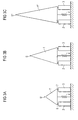
- Figures 3a to 3c each show an actuator 1,1 ', 1 "analogous to Figure 1, in which now the lengths of the oblique Sides of the transmitter body 1.1 '', 1 '' are designed differently are.
- FIG. 3b shows an actuator 1, which is the actuator 1 from Figure 1 corresponds.
- Figure 3a shows an actuator that one Transmitter body 1 'with shortened oblique sides for change of the ratio of height to width.
- the drive tip is S ' wider than in Figure 3b.
- Figure 3c shows an actuator that has a transmitter body 1 '' with extended sloping sides. This gives a reduced compared to the actuator in Figure 3b Power transmission at high speed.
- a shape of the transmitter body 1,1', 1 '' becomes.
- a transmitter body 1, 1 ', 1' ' can be used with different drive tips S, S ', S ", as a comparison between Figure 3a and 3b shows.
- a transmitter body 1,1 ', 1' 'with different Shape of the cross-sectional area e.g. B. angular, round, chamfered or can also be used in any shape.
- Figure 4 shows a sectional side view of a rotary motor analogous to Figure 1, in which the rotor R in Form of a shaft rotatably mounted about its longitudinal axis I. is.
- Figure 5 shows a side view of a linear motor in which a linear movement by means of the electromechanical actuator in the x direction (symbolized by the arrow) one general boom G, which is passed through two bearings L, is feasible.
- the linkage G can be a shaft, for example be or a flat ribbon. It is also possible to attach to an output body (5, R, S) to attack several actuators, for example to increase the torque or simultaneous rotary and linear movement.
- Figure 6 shows an oblique view of an embodiment of an engine for the realization of slowly rotating and heavily loaded Drives.
- the two actuators 2, 3 act as described above the rotation of the output body R, which is in the form of a Roller is present.
- An additional actuator 8 is used for locking during the frictional contact open at the front end used.
- Figure 7 shows a sectional side view of the (x, y) plane another embodiment of a motor, at an output body 5 in the form of a shaft by means of a electromechanical actuator can be excited to rotate is.
- the shaft 5 is now for reasons of space saving between the actuators 2.3 through it.
- the transmitter body 1 * is replaced by an under Compressed spring element 4 held on the transmitter elements 6.7 pressed.
Abstract
Description
Die Erfindung betrifft einen elektromechanisch antreibbaren Stellantrieb, Motoren unter Verwendung dieses Stellantriebs sowie ein Verfahren zum Betrieb des Stellantriebs.The invention relates to an electromechanically drivable Actuator, motors using this actuator and a method for operating the actuator.
Im Zuge der fortschreitenden technischen Entwicklung findet sich die Tendenz, eine Vielzahl von Vorgängen und Prozessen durch Automatisierung optimal zu fahren. Während in den ersten beiden benötigten Gliedern der dazu benötigten Systemeden Meßwertaufnehmern (Sensoren) für physikalische und chemische Größen sowie den für die Informationsverarbeitung benötigten Elektroniken - durch den Einsatz neuer Technologien beträchtliche Fortschritte erzielt wurden, beruhen die für mechanische Verstellungen benötigten Aktoren weitgehend noch auf der zwar gut erprobten, jedoch limitierten Technologie elektromagnetischer Stellantriebe.In the course of advancing technical development takes place the tendency to have a variety of operations and processes to drive optimally through automation. While in the first both required links of the required systems Transducers (sensors) for physical and chemical Sizes as well as those required for information processing Electronics - through the use of new technologies Considerable progress has been made on the basis of mechanical adjustments still largely required actuators on the well-tried but limited technology electromagnetic actuators.
Bei einem elektromagnetischen Stellantrieb wird, um langsame Drehungen bei hohem Moment zu realisieren, ein schnell drehender elektromagnetischer Motor mit einem Untersetzungsgetriebe kombiniert. Dies bedingt zwangsläufig relativ große Bauformen und hohes Gewicht, lange Start-Stop-Zeiten (das Trägheitsmoment des Rotors muß auf hohe Drehzahlen beschleunigt werden) sowie ein nicht zu vernachlässigendes Spiel und Preis des starken Untersetzungsgetriebes.With an electromagnetic actuator it is slow To realize rotations at high moment, a fast rotating one electromagnetic motor with a reduction gear combined. This inevitably requires relatively large ones Designs and high weight, long start-stop times (the The moment of inertia of the rotor must be accelerated to high speeds ) and a not to be neglected game and Price of the strong reduction gear.
Aus DE 38 33 342 bekannt ist ein piezoelektrischer Stellantriebe, der auf dem Prinzip des inversen piezoelektrischen Effekt gründet. Hier ist jedoch das Grundproblem zu lösen, daß nur eine geringe Antriebslänge realisierbar ist: Durch die Volumenänderung des Piezoeffekts sind typischerweise maximale Antriebslängen von 1/1000 der Piezoaktorabmessungen möglich, d.h. bei typischen Aktorlängen von 0,5 cm bis 5 cm, insbesondere um 20 µm, stehen Bewegungswege von 5 µm bis 50 µm zur Verfügung. Zudem sind einer hohen Wiederholfrequenz der Antriebsschritte Grenzen gesetzt, da bei Frequenzen im kHz-Bereich starke Schallabstrahlungen auftreten (20 µm · 1000/s = 20 mm/s). Zur Realisierung von relativ langsam drehenden (50 U/min) oder verstellenden (1 cm/s) Antrieben ist eine erhebliche Transformation der Bewegungsamplitude nötig.DE 38 33 342 discloses a piezoelectric actuator, which is based on the principle of inverse piezoelectric Effect based. But here the basic problem has to be solved, that only a small drive length can be realized: by the volume change of the piezo effect is typically maximum Drive lengths of 1/1000 of the piezo actuator dimensions possible, i.e. with typical actuator lengths from 0.5 cm to 5 cm, in particular around 20 µm, there are movement paths from 5 µm to 50 µm available. They also have a high repetition rate of the drive steps set limits, since frequencies in kHz range strong sound emissions occur (20 µm · 1000 / s = 20 mm / s). To realize relative slowly rotating (50 rpm) or adjusting (1 cm / s) drives is a significant transformation of the movement amplitude necessary.
Beispielsweise DE 38 33 342 verwendet neben einer sehr hohen Wiederholfrequenz der Bewegung im Ultraschallbereich (20-40 kHz) eine Amplitudentransformation der Primäramplitude durch die Verwendung resonanter Aktoren. Mit der Piezokeramik wird so bei geringer Bewegungsamplitude am Knotenpunkt der Schwingung eine resonante Schwingung eines Körpers angeregt, wodurch am Schwingungsbauch eine typischerweise um den Faktor 50 erhöhte Bewegungsamplitude zu Verfügung steht. In der Praxis hat sich jedoch der resonante Betrieb als kritisch erwiesen. Zur Erzielung einer hohen Amplitudentransformation müssen Resonatoren hoher Güte verwendet werden, so daß die Resonanz äußerst schmalbandig wird. Dadurch ergeben sich schwer überwindliche Schwierigkeiten bei der Ansteuerung, wenn die Resonanzfrequenz z.B. durch Temperaturänderungen oder Änderungen des Belastungszustandes schwankt. Außerdem sind bei der Fertigung sehr geringe Toleranzen einzuhalten.For example, DE 38 33 342 used in addition to a very high Repetition frequency of the movement in the ultrasound range (20-40 kHz) an amplitude transformation of the primary amplitude through the use of resonant actuators. With the piezoceramic is so with a small movement amplitude at the node of Vibration excited a resonant vibration of a body which causes a typically by a factor at the antinode 50 increased movement amplitude is available. In practice however, resonant operation has proven critical. To achieve a high amplitude transformation High quality resonators are used so that the resonance becomes extremely narrow-band. This results in difficult insurmountable difficulties in the control when the Resonance frequency e.g. through temperature changes or changes of the load condition fluctuates. In addition, at to comply with very low tolerances during production.
Es ist die Aufgabe der vorliegenden Erfindung, eine Möglichkeit für einen kostengünstigen, kompakten und leichten Antrieb mit geringem Spiel bereitzustellen.It is the object of the present invention, one way for an inexpensive, compact and light drive to provide with little play.
Diese Aufgabe wird durch einen Stellantrieb gemäß Patentanspruch 1, durch einen Motor gemäß Patentanspruch 9 sowie durch ein Antriebsverfahren gemäß Patentanspruch 12 gelöst. Vorteilhafte Ausgestaltungen sind den Unteransprüchen entnehmbar.This object is achieved by an actuator according to claim 1, by a motor according to claim 9 and solved by a drive method according to claim 12. Advantageous refinements can be found in the subclaims.
Dazu weist ein elektromechanischer Stellantrieb mindestens einen ersten elektromechanischen Aktuator und einen davon räumlich getrennten zweiten elektromechanischen Aktuator auf. Dabei weist ein elektromechanischer Aktuator mindestens ein elektromechanisches Element auf. Unter einem elektromechanischen Element wird ein Körper verstanden, bei dem ein Volumen durch Anlegen eines elektrischen Signals (Strom, Spannung etc.) gedehnt wird, wodurch sich ein Hub des Aktuators ergibt.At least one electromechanical actuator has this a first electromechanical actuator and one of them spatially separated second electromechanical actuator. An electromechanical actuator has at least one electromechanical element. Under an electromechanical Element is understood to be a body in which a volume by applying an electrical signal (current, voltage etc.) is stretched, which results in a stroke of the actuator.
Beispiele für elektromechanische Elemente sind elektrostriktive Elemente, magnetostriktive Elemente (z. B. inclusive einer elektrischen Windung) oder piezoelektrische Elemente. Diese Elemente haben gemeinsam, daß sie sehr präzise ansteuerbar sind und hohe Druckkräfte aufbringen können. Andererseits ist ihnen ein in Vergleich zur Bauteillänge geringer Hub dl gemein, der ihre direkte Anwendung einschränkt.Examples of electromechanical elements are electrostrictive Elements, magnetostrictive elements (e.g. including one electrical winding) or piezoelectric elements. These elements have in common that they can be controlled very precisely are and can apply high pressure forces. On the other hand is less than the component length Hub dl common that limits their direct application.
Weiterhin ist ein Transmitterkörper vorhanden der auf den Aktuatoren aufsitzt. Eine Dehnung der Aktuatoren in Richtung des Transmitterkörpers ist steuerbar, z. B. durch Anlegen einer elektrischen Spannung. Der Hub dl der Aktuatoren kann durch Einsatz des Transmitterkörpers transformiert, d.h. in der Regel stark vergrößert, werden. Der Transmitterkörper wirkt dabei als nichtresonant betriebener biaktiver Hebel. Ein Abtriebskörper wird bei Vorliegen eines Friktionskontaktes mit dem Transmitterkörper mitgeführt.There is also a transmitter body on the actuators sits on. An expansion of the actuators in the direction the transmitter body is controllable, e.g. B. by creating one electrical voltage. The stroke dl of the actuators can transformed by using the transmitter body, i.e. in usually greatly enlarged. The transmitter body acts as a non-resonant operated biactive lever. An output body is in the presence of a friction contact carried along with the transmitter body.
Durch den Hub der Aktuatoren können drei Funktionen realisiert werden: ein Andruck einer Fläche des Transmitterkörpers auf dem Abtriebskörper zum Schließen des Friktionskontaktes, ein Antrieb des Abtriebskörpers bei geschlossenem Friktionskontakt und ein Lösen des Kontaktes zwischen Transmitterkörper und Abtriebskörper. Dadurch ist z.B. ein intermittierendes Schließen des Friktionskontaktes zur schrittweisen Bewegung des Abtriebskörpers möglich.Three functions can be realized by the stroke of the actuators become: a pressure of a surface of the transmitter body on the output body to close the friction contact, a drive of the output body with closed friction contact and releasing the contact between the transmitter body and output body. This means e.g. an intermittent Closing the friction contact for gradual movement of the output body possible.
Es ist auch der Einsatz mehrerer elektromechanischer Stellantriebe zum Antrieb eines Abtriebskörpers möglich. Ebenso können mittels eines elektromechanischen Stellantriebs mehrere Abtriebskörper angetrieben werden.It is also the use of several electromechanical actuators possible to drive an output body. As well can use several electromechanical actuators Output body are driven.
Die Steuerung der Dehnung ist nicht eingeschränkt, kann also separat oder gekoppelt erfolgen. In der Regel werden die Aktuatoren elektronisch angesteuert werden.The control of the stretch is not restricted, so it can separately or coupled. As a rule, the actuators can be controlled electronically.
Für den elektromechanischen Stellantrieb ergeben sich unter anderem folgende Vorteile:
- hohe Übersetzung des Hubs der Aktuatoren,
- einfacher Aufbau,
- durch die nichtresonante Ausführung ist keine besondere Maßhaltung/Toleranz in der Fertigung erforderlich.
- es sind die vier Betriebszustände: Linkslauf, Rechtslauf, Blockieren, Freilauf einstellbar,
- eine Drehgeschwindigkeit ist flexibel, z. B. elektronisch, regelbar,
- eine maximale Kraftübertragung (Drehgeschwindigkeit / Drehmoment) und Antriebsgeschwindigkeit ist durch eine Geometrieanpassung sehr einfach einstellbar, d.h. ein Antrieb eines Motors ist problemlos skalierbar.
- high translation of the stroke of the actuators,
- easy construction,
- due to the non-resonant design, no special dimensional tolerance / tolerance is required in production.
- the four operating states are adjustable: counterclockwise, clockwise, blocking, free running,
- a rotational speed is flexible, e.g. B. electronic, adjustable,
- Maximum power transmission (rotational speed / torque) and drive speed can be set very easily by adapting the geometry, ie a drive of a motor can be scaled without problems.
Der Transmitterkörper ist vorzugsweise steif ausgeführt.The transmitter body is preferably stiff.
Es ist vorteilhaft, wenn die Aktuatoren nach einem magnetostriktiven, einem elektrostriktiven oder insbesondere einem piezoelektrischen Prinzip antreibbar sind.It is advantageous if the actuators follow a magnetostrictive, an electrostrictive or in particular one Piezoelectric principle can be driven.
Dabei ist es zur einfachen Herstellung, hohen Zuverlässigkeit und besonders präzisen Ansteuerung günstig, wenn die Aktuatoren in Form eines Vielschicht-Piezoaktors vorliegen, insbesondere in Niedervolttechnik.It is easy to manufacture, high reliability and particularly precise control cheaply when the actuators are in the form of a multilayer piezo actuator, in particular in low-voltage technology.
Zur Vermeidung schädlicher Zugspannungen, insbesondere bei keramischen elektromechanischen Elementen, ist es günstig, wenn die Aktuatoren unter einer Druckvorspannung stehen. To avoid harmful tensile stresses, especially at ceramic electromechanical elements, it is convenient if the actuators are under pressure.
Es ist besonders vorteilhaft, wenn der Transmitterkörper mittels eines Federelementes auf die Aktuatoren gedrückt wird, weil so gleichzeitig ein guter Sitz des Transmitterkörpers auf den Aktuatoren und eine Druckvorspannung der Aktuatoren erreicht werden kann. Gleichzeitig sind Effekte thermischer Ausdehnung ausgleichbar.It is particularly advantageous if the transmitter body is by means of a spring element is pressed onto the actuators, because at the same time the transmitter body fits well on the actuators and a pressure preload of the actuators can be achieved. At the same time, effects are more thermal Expansion can be compensated.
Es ist auch günstig, wenn der Transmitterkörper eine keilförmige Querschnittsfläche aufweist, wobei er mit einer Bodenfläche auf den Aktuatoren aufsitzt, weil sich so ein einfach ansteuerbarer und vielseitig einsetzbarer Stellantrieb ergibt.It is also convenient if the transmitter body is wedge-shaped Has cross-sectional area, with a bottom surface sits on the actuators because such an easy one controllable and versatile actuator results.
Dabei ist es zur Verringerung eines Abriebs und zur Vergrößerung des Friktionskontaktes vorteilhaft, wenn die der Bodenfläche gegenüberliegende Antriebssspitze abgeflacht ist.It is to reduce abrasion and increase of the frictional contact is advantageous if that of the floor surface opposite drive tip is flattened.
Zur Gewährleistung eines guten Kontakts zwischen dem Transmitterkörper und den Aktuatoren über den gesamten Bewegungsbereich des Transmitterkörpers ist es günstig, wenn zwischen den Aktuatoren und dem Transmitterkörper jeweils ein Übertragerelement zur verbesserten Kontaktauflage vorhanden ist. Das Übertragerelement kann z.B. eine Kugelscheibe mit Sitz sein.To ensure good contact between the transmitter body and the actuators over the entire range of motion of the transmitter body, it is favorable if between the actuators and the transmitter body each have a transmitter element for improved contact support is available. The Transmitter element can e.g. be a spherical disc with seat.
Bei einem Motor, der einen elektromechanischen Stellantrieb nach dem oben beschriebenen Prinzip aufweist, ist also eine Bewegung eines Abtriebskörpers mittels einer durch einen Friktionskontakt übertragenen Bewegung des Transmitterkörpers steuerbar.For a motor that has an electromechanical actuator according to the principle described above, is therefore a Movement of an output body by means of one Frictional contact transmitted movement of the transmitter body controllable.
Dabei ist es vorteilhaft, wenn der Motor einen Abtriebskörper aufweist, der mittels der durch den Friktionskontakt übertragenen Bewegung des Transmitterkörpers drehbar ist, z. B. eine Welle.It is advantageous if the motor has an output body has, which is transmitted by means of the friction contact Movement of the transmitter body is rotatable, for. Legs Wave.
Es kann auch günstig sein, wenn der Motor einen Abtriebskörper aufweist, welcher mittels der durch den Friktionskontakt übertragenen Bewegung des Transmitterkörpers linearverschiebbar ist, z.B. einen Kolben oder ein Blech. Der Abtriebskörper kann auch durch den mindestens einen Stellantrieb sowohl drehbar als auch linearverschiebbar sein.It can also be beneficial if the engine has an output body has, which by means of the friction contact transmitted movement of the transmitter body is linearly displaceable is, e.g. a piston or sheet. The output body can both by the at least one actuator be rotatable and linearly displaceable.
Bei einem Verfahren zum Betrieb des Stellantriebs wird ein Hub dl2 des ersten Aktuators und ein Hub dl3 des zweiten Aktuators jeweils periodisch verändert, so daß sich ein regelmäßiger Antrieb ergibt. Es sind aber auch andere, z. B. nicht-periodische, Bewegungen möglich.In a method for operating the actuator, a stroke dl 2 of the first actuator and a stroke dl 3 of the second actuator are each changed periodically, so that a regular drive results. But there are also others, e.g. B. non-periodic movements possible.
Es ist besonders vorteilhaft, wenn der Hub dl2 des ersten Aktuators 2 gemäß der Gleichung dl2 = dl0 · sin (ω·t) eingestellt wird, und der Hub dl3 des zweiten Aktuators gemäß der Gleichung dl3 = dl0 · sin (ω·t + ) eingestellt wird, wobei dl0 eine Amplitude, z. B. den maximalen Hub, darstellt. ω entspricht einer Kreisfrequenz und einem Phasenwinkel. Bei einem piezoelektrischen Stellelement ist ein solcher Hub durch eine analoge Einstellung der an den Piezoelementen anliegenden Ansteuerspannung einstellbar, weil sich die Ansteuerspannung und der Hub in guter Näherung linear zueinander verhalten.It is particularly advantageous if the stroke dl 2 of the first actuator 2 is set according to the equation dl 2 = dl 0 · sin (ω · t), and the stroke dl 3 of the second actuator according to the equation dl 3 = dl 0 · sin (ω · t + ) is set, where dl 0 is an amplitude, z. B. represents the maximum stroke. ω corresponds to an angular frequency and a phase angle. In the case of a piezoelectric actuating element, such a stroke can be adjusted by an analog setting of the drive voltage applied to the piezo elements, because the drive voltage and the stroke have a linear approximation to one another.
Zum Herstellung eines hohen Vortriebs des Abtriebkörpers ist es vorteilhaft, wenn der Phasenwinkel = 180° oder = -180° beträgt. To produce a high propulsion of the output body it is advantageous if the phase angle = 180 ° or = -180 ° is.
Als ein Anwendungsgebiet eines solches Stellantriebs ist das
sogenannte automatisierte Haus gegeben:
Ein weiteres Anwendungsgebiet liegt auf dem Gebiet der Industrietechnik:
Auch ein Einsatz in der Automobiltechnik ist möglich:
Ein weiteres Anwendungsgebiet ist der Autofocusantrieb in Kameraobjektiven (EOS von CANON) bei der im wesentlichen die Kriterien extrem schnell, kompakt und leicht gelten.Another area of application is the autofocus drive in camera lenses (EOS from CANON) at which essentially the Criteria apply extremely quickly, compactly and easily.
Selbstverständlich sind die angeführten Beispiele von Anwendungsgebieten nicht abschließend, sondern zeigen nur einige vorteilhafte Anwendungen auf. Of course, the examples given are of application areas not conclusively, but only show a few advantageous applications.
In den folgenden Ausführungsbeispielen wird der Stellantrieb schematisch näher ausgeführt.
- Figur 1
- zeigt eine Ausführungsform eines mit einem elektromechanischen Stellantrieb angetriebenen Motors,
- Figur 2
- zeigt Bewegungen der Antriebsspitze für verschiedene Phasenwinkel ,
- Figuren 3a bis 3c
- zeigt Stellantriebe mit unterschiedlichen Transmitterkörpern,
- Figur 4
- zeigt einen mittels des elektromechanixschen Stellantriebs drehbar angetriebenen Motor,
- Figur 5
- zeigt einen mittels des elektromechanischen Stellantriebs angetriebenen Linearmotor,
- Figur 6
- zeigt eine weitere Ausführungsform des drehbar angetriebenen Motors,
- Figur 7
- zeigt eine weitere Ausführungsform des drehbar angetriebenen Motors.
- Figure 1
- shows an embodiment of a motor driven with an electromechanical actuator,
- Figure 2
- shows movements of the drive tip for different phase angles ,
- Figures 3a to 3c
- shows actuators with different transmitter bodies,
- Figure 4
- shows a motor rotatably driven by means of the electromechanical actuator,
- Figure 5
- shows a linear motor driven by means of the electromechanical actuator,
- Figure 6
- shows a further embodiment of the rotatably driven motor,
- Figure 7
- shows a further embodiment of the rotatably driven motor.
Figur 1 zeigt als Schnittdarstellung in Seitenansicht auf die (x,y)-Ebene einen Motor, der mittels eines elektromechanischen Stellantriebs zu einer Drehbewegung anregbar ist.Figure 1 shows a sectional side view of the (x, y) plane a motor that uses an electromechanical Actuator can be excited to a rotary movement.
Der Stellantrieb besteht aus einem Transmitterkörper 1, einem ersten piezomechanischen Aktuator 2, einem zweiten piezomechanischen Aktuator 3, einem Federelement 4, und zwei Übertragerelementen 6,7. Durch den Stellantrieb wird ein Abtriebskörper 5 des Motors angetrieben. Der Abtriebskörper 5 liegt hier in Form eines Rotors R, z. B. einer Welle, vor, welcher durch die Mitführung mit dem Transmitterkörper 1 zu einer Drehung angeregt wird. Das elektromechanische Element der Aktuatoren 2,3 ist jeweils ein Vielschicht-Piezoaktor in Niedervolttechnik, dessen Hub dl unter Ausnutzung des bekannten d33-Längseffektes in Richtung ihrer Längsachse wirkt. The actuator consists of a transmitter body 1, a first piezomechanical actuator 2, a second piezomechanical actuator 3, a spring element 4, and two transmitter elements 6, 7. An output body 5 of the motor is driven by the actuator. The output body 5 is here in the form of a rotor R, z. B. a shaft, which is excited to rotate by being carried along with the transmitter body 1. The electromechanical element of the actuators 2, 3 is in each case a multilayer piezo actuator using low-voltage technology, the stroke d1 of which acts in the direction of its longitudinal axis using the known d 33 longitudinal effect.
Dabei liegt der Transmitterkörper 1 über das erstes Übertragerelement 6 auf dem ersten Aktuator 2 und über das zweites Übertragerelement 7 auf dem zweiten Aktuator 3 auf. Mittels der Zugspannung des Federelementes 4 wird der Transmitterkörper 1 dergestalt gegen die beiden Aktuatoren 2,3 gezogen, daß der Druck in etwa der Mitte der Arbeitsgeraden der beiden Aktuatoren 2,3 liegt. Dadurch wird einerseits ein sicherer Sitz des Transmitterkörpers 1 auf den Aktuatoren 2,3 gewährleistet und andererseits ist eine Druckvorspannung der piezomechanischen Aktuatoren 2,3 gegeben.The transmitter body 1 lies over the first transmitter element 6 on the first actuator 2 and over the second Transmitter element 7 on the second actuator 3. Means the tension of the spring element 4 becomes the transmitter body 1 pulled against the two actuators 2, 3 in such a way that the pressure in the middle of the working line of the two actuators 2.3 lies. On the one hand, this ensures a secure fit of the transmitter body 1 on the actuators 2, 3 guaranteed and on the other hand is a compressive bias of the piezomechanical Actuators 2.3 given.
Der Transmitterkörper 1 ist steif ausgeführt. Mit seiner gehärteten Antriebsspitze S kann er im Bereich eines Kontaktpunkts Pk mit dem Rotor R in Friktionskontakt gebracht werden.The transmitter body 1 is stiff. With its hardened He can drive tip S in the area of a contact point Pk be brought into frictional contact with the rotor R.
Die piezomechanischen Aktuatoren 2,3 sind so ausgerichtet,
daß ihr (positiver und/oder negativer) Hub parallel zur y-Achse
in Richtung des Transmitterkörpers 1 wirkt.
Die Aktuatoren 2,3 umfassen außer dem Piezoaktor mit seinen
elektrischen Anschlüssen auch eine Kopfplatte und eine Fußplatte.The piezomechanical actuators 2, 3 are aligned so that their (positive and / or negative) stroke acts parallel to the y-axis in the direction of the transmitter body 1.
In addition to the piezo actuator with its electrical connections, the actuators 2, 3 also comprise a head plate and a foot plate.
Eine gleichartige Ansteuerung zur Elongation beider Aktuatoren 2,3 bewirkt einen Kraftschluß der Transmitterspitze S auf dem Abtriebskörper R, eine gleichartige Ansteuerung der Aktuatoren 2,3 zur Kontraktion bewirkt ein Öffnen des Friktionskontaktes. Eine ungleichmäßige Ansteuerung beider Aktuatoren 2,3 (z. B. Elongation des ersten Aktuators 2 und Kontraktion des zweiten Aktuators 3) bewirkt eine Bewegung der Antriebspitze S des Transmitterkörpers 1 in Richtung des kontrahierten Aktuators 2,3 (z.B. des zweiten Aktuators 3).A similar control to elongate both actuators 2, 3 causes the transmitter tip S to engage the output body R, a similar control of the actuators 2,3 for contraction causes the friction contact to open. An uneven control of both actuators 2,3 (e.g. elongation of the first actuator 2 and contraction of the second actuator 3) causes a movement of the Drive tip S of the transmitter body 1 in the direction of the contracted Actuators 2, 3 (e.g. the second actuator 3).
Durch den gleichgerichteten Anteil der Bewegung der beiden Aktuatoren 2,3 wird somit der Andruck bzw. das Öffnen und Schließen des Friktionskontaktes gesteuert, durch den Differenzanteil hingegen der Antrieb des Rotors R senkrecht zur Hubrichtung der Aktuatoren 2,3. Die Antriebsspitze S führt den Rotor R in die gleiche Richtung mit. Beispielsweise wird bei einer Elongation des ersten Aktuators 2 und einer Kontraktion des zweiten Aktuators 3 bei gleichzeitigem Friktionskontakt der Rotor R gegen den Uhrzeigersinn gedreht.By the same proportion of the movement of the two Actuators 2, 3 is the pressure or opening and Controlled closing of the friction contact by the difference however, the drive of the rotor R perpendicular to Stroke direction of the actuators 2,3. The drive tip S leads the rotor R in the same direction. For example with an elongation of the first actuator 2 and a contraction of the second actuator 3 with simultaneous friction contact the rotor R turned counterclockwise.
Wenn der Transmitterkörper 1 nach Erreichen des maximalen Hubunterschiedes zwischen den beiden Aktuatoren 2,3 durch Lösen des Kontaktes zum Rotor R wieder an der anfänglichen Position aufgesetzt wird, ergibt sich ein intermittierender Antrieb des Rotors R.If the transmitter body 1 after reaching the maximum Stroke difference between the two actuators 2, 3 by loosening of contact with the rotor R again at the initial position is put on, there is an intermittent drive of the rotor R.
Figur 2 zeigt eine mögliche Bewegungskurve der Kontaktspitze
S in der (x,y)-Ebene in Abhängigkeit eines Phasenwinkels .
Dazu wird der Hub dl2 des ersten Aktuators 2 und der Hub dl3
des zweiten Aktuators 3 gemäß der Gleichungen
Eine Bewegung gemäß Gl. [1] ist bei einem piezoelektrisch angetriebenen
Stellantrieb analog zu einer periodischen Ansteuerspannung
U2 bzw. U3 am ersten Aktuator 2 bzw. am zweiten
Aktuator 3 mit gleicher Frequenz gemäß
Bei einer Phasenverschiebung von = 180° bzw. -180° (gegengerichtete Ansteuerung) liegt als Bewegungskurve der Antriebspitze S eine Ellipse vor. Die dabei gegebene Abweichung von der Kreisform ist durch die Geometrie des Transmitterkörpers 1 einstellbar. Ein Phasenwinkel = 180° bzw. -180° entspricht einen maximalen Drehzahl bzw. Translationsgeschwindigkeit des Motors.With a phase shift of = 180 ° or -180 ° (opposite Control) is the movement curve of the drive tip S an ellipse in front. The given deviation of the circular shape is due to the geometry of the transmitter body 1 adjustable. A phase angle = 180 ° or -180 ° corresponds to a maximum speed or translation speed of the motor.
Die Größe der Bewegung der Antriebsspitze S in x-Richtung ("x-Hub") ist direkt durch eine Wahl der Geometrie des Transmitterkörpers 1 einstellbar, insbesondere durch das Verhältnis von Höhe zu Breite. Dadurch wird es möglich, daß der x-Hub des Transmitterkörpers 1 um ein Vielfaches größer ist als der maximale Hubs dl der Aktuatoren 2,3. Dies entspricht einer Hubübersetzung mit Änderung der Bewegungsrichtung. Die Aktuatoren 2,3 werden dabei in der Regel vorteilhafterweise nur unwesentlich gebogen, insbesondere, wenn die Übertragerelemente 6,7 frei beweglich gelagert sind.The size of the movement of the drive tip S in the x direction ("x-stroke") is directly through a choice of the geometry of the transmitter body 1 adjustable, especially by the ratio from height to width. This makes it possible for the x-stroke of the transmitter body 1 is many times larger than the maximum stroke dl of the actuators 2.3. This corresponds to one Stroke ratio with change in the direction of movement. The Actuators 2, 3 are usually advantageous only slightly bent, especially when the transmitter elements 6.7 are freely movable.
Wie aus dieser Figur zu erkennen ist, bewirkt die Bewegungskurve ein weiches Aufsetzen der Antriebspitze S auf dem Abtriebskörper 5,R,S. Damit tritt das bei bisherigen monomodalen Motorprinzipien bekannte und schwierig zu behebende Problem des Verschleißes am Friktionskontakt nicht signifikant in Erscheinung.As can be seen from this figure, the movement curve a soft placement of the drive tip S on the output body 5, R, S. This is the case with previous monomodal models Motor principles known and difficult problem to fix the wear on the friction contact is not significant in appearance.
Bei Abweichungen von diesen Werten des Phasenwinkels liegt ein Antrieb des Abtriebskörpers 5,R,S mit verminderter Geschwindigkeit vor. Bei einer Phasenlage von = 0° liegt kein Antrieb vor, obwohl zwischenzeitlich der Friktionskontakt geöffnet wird. Dies erlaubt die Realisierung eine Freilaufzustandes (aktive Entblockierung) in einem elektromechanischen Motor, der ansonsten im ausgeschalteten Zustand die Bewegung mit dem maximalen Haltemoment blockiert.If there are deviations from these values of the phase angle a drive of the output body 5, R, S at a reduced speed in front. With a phase position of = 0 ° no drive before, although in the meantime the friction contact is opened. This allows the implementation of a free running state (active deblocking) in an electromechanical Engine, which otherwise the off Movement blocked with the maximum holding torque.
Es sind auch andere als sinusförmige Ansteuerspannungen möglich. Auch ist es beispielsweise zur Realisierung einer dreidimensionalen Bewegungskurve möglich, einen Transmitterkörper 1,1',1'' mit mehr als zwei Aktuatoren 2,3 auszustatten oder Aktuatoren 2,3 gegeneinander zu verkippen. Control voltages other than sinusoidal are also possible. It is also used, for example, to implement a three-dimensional one Movement curve possible, a transmitter body 1.1 ', 1' 'with more than two actuators 2.3 or Tilt actuators 2.3 against each other.
Die Figuren 3a bis 3c zeigen jeweils einen Stellantrieb 1,1',1"analog zu Figur 1, bei dem nun die Längen der schrägen Seiten des Transmitterkörpers 1,1'',1'' verschieden ausgeführt sind.Figures 3a to 3c each show an actuator 1,1 ', 1 "analogous to Figure 1, in which now the lengths of the oblique Sides of the transmitter body 1.1 '', 1 '' are designed differently are.
Figur 3b zeigt einen Stellantrieb 1, der dem Stellantrieb 1 aus Figur 1 entspricht.FIG. 3b shows an actuator 1, which is the actuator 1 from Figure 1 corresponds.
Figur 3a zeigt im Gegensatz dazu einen Stellantrieb, der einen Transmitterkörper 1' mit verkürzten Schrägseiten zur Änderung des Verhältnisses von Höhe zu Breite aufweist. Dadurch ergibt sich im Vergleich zum Stellantrieb in Figur 3b eine höhere Kraftübertragung und eine kleinere Drehzahl an der Antriebsspitze S'. Zur Sicherstellung des Friktionskontaktes bei höherer Kraftübertragung ist die Antriebsspitze S' zudem breiter ausgeführt als in Figur 3b.In contrast, Figure 3a shows an actuator that one Transmitter body 1 'with shortened oblique sides for change of the ratio of height to width. Thereby compared to the actuator in FIG higher power transmission and a lower speed at the drive tip S '. To ensure frictional contact with higher power transmission, the drive tip is S ' wider than in Figure 3b.
Figur 3c zeigt einen Stellantrieb, der einen Transmitterkörper 1'' mit verlängerten Schrägseiten aufweist. Dadurch ergibt sich im Vergleich zum Stellantrieb in Figur 3b eine reduzierte Kraftübertragung bei hoher Drehzahl.Figure 3c shows an actuator that has a transmitter body 1 '' with extended sloping sides. This gives a reduced compared to the actuator in Figure 3b Power transmission at high speed.
Aus den Figuren 3a bis 3c ergibt sich, daß die maximale Drehgeschwindigkeit / Drehmoment der Antriebsspitze S,S',S'' durch eine Wahl der Geometrie des Transmitterkörpers 1,1',1'' flexibel einstellbar ist. Daher wird der Stellantrieb, beispielsweise durch einfaches Auswechseln des Transmitterkörpers 1,1',1'', problemlos skalierbar. So wird der Aufwand zur Anpassung an verschiedene Antriebssituationen sehr klein, und eine Anpassung der Motoren an die benötigte Drehzahl bzw. das Drehmonent oder einen Linearvorschub möglich.It can be seen from FIGS. 3a to 3c that the maximum rotational speed / Torque of the drive tip S, S ', S' ' by choosing the geometry of the transmitter body 1,1 ', 1' ' is flexibly adjustable. Therefore, the actuator, for example by simply replacing the transmitter body 1.1 ', 1' ', easily scalable. So the effort becomes Adaptation to different drive situations very small, and an adaptation of the motors to the required speed or that Torque or a linear feed possible.
Außer einer Änderung der Abmessungen des Transmitterkörpers 1,1',1'' eine Form des Transmitterkörpers 1,1',1'' verändert werden. Beispielsweise kann ein Transmitterkörper 1,1',1'' mit unterschiedlicher Antriebsspitze S,S',S" eingesetzt werden, wie ein Vergleich zwischen Figur 3a und 3b zeigt. Auch kann ein Transmitterkörper 1,1',1'' mit unterschiedlicher Form der Querschnittsfläche, z. B. eckig, rund, angefast oder auch beliebig geformt eingesetzt werden.Except for changing the dimensions of the transmitter body 1,1 ', 1' 'changed a shape of the transmitter body 1,1', 1 '' become. For example, a transmitter body 1, 1 ', 1' ' can be used with different drive tips S, S ', S ", as a comparison between Figure 3a and 3b shows. Also can a transmitter body 1,1 ', 1' 'with different Shape of the cross-sectional area, e.g. B. angular, round, chamfered or can also be used in any shape.
Dies ist z. B. sinnvoll, wenn der Stellantrieb von einem bidirektionalen Antrieb (links/rechts) auf einen unidirektionalen Antrieb (nur links / nur rechts) umgestellt werden soll.This is e.g. B. useful if the actuator from a bidirectional Drive (left / right) on a unidirectional Drive (only left / only right) should be changed.
Figur 4 zeigt als Schnittdarstellung in Seitenansicht einen rotatorische Motor analog zu Figur 1, bei dem der Rotor R in Form einer um ihre Längsachse I drehbar gelagerten Welle ausgeführt ist.Figure 4 shows a sectional side view of a rotary motor analogous to Figure 1, in which the rotor R in Form of a shaft rotatably mounted about its longitudinal axis I. is.
Der Rotor R steht, wie auch andere Abtriebskörper 5, in Anwendungen üblicherweise unter Belastung. Dadurch kann auf ihn ein nicht unerhebliches rücktreibendes Drehmoment ausgeübt werden. Demgegenüber steht der nur intermittierend erfolgende Antrieb durch den Stellantrieb 1. In einem Teil der Fälle reicht das Trägheitsmoment des Rotors R aus, um ein Rückdrehen während der Öffnungsphase des Friktionskontaktes zu vermeiden. Falls die nicht der Fall ist (z.B. bei sehr langsamdrehenden und/oder stark belasteten Motoren), kann:
- entweder mindestens ein zweiter Stellantrieb eingesetzt werden, der einen um 180° phasenverschobenen Antrieb des Rotor S bewirkt, oder
- mittels eines weiteren Aktuators 8, oder einer anderen Bremse, der Rotor R in der Öffnungsphase arretiert werden. Eine solche Ausgestaltung eines Motors zeigt z. B. Figur 6.
- either at least one second actuator is used, which effects a 180 ° phase-shifted drive of the rotor S, or
- the rotor R can be locked in the opening phase by means of a further actuator 8 or another brake. Such an embodiment of a motor shows, for. B. Figure 6.
Die gleichen Überlegungen gelten auch für einen Linearmotor.The same considerations apply to a linear motor.
Figur 5 zeigt in Seitenansicht einen Linearmotor, bei dem mittels des elektromechanischen Stellantriebs eine Linearbewegung in x-Richtung (symbolisiert durch den Pfeil) eines allgemeinen Gestänges G, das durch zwei Lager L geführt wird, realisierbar ist. Das Gestänge G kann zum Beispiel eine Welle sein oder ein flaches Band. Auch ist es möglich, an einen Abtriebskörper (5,R,S) mehrere Stellantriebe angreifen zu lassen, beispielsweise zur Verstärkung des Drehmoments oder zur gleichzeitigen Dreh- und Linearbewegung.Figure 5 shows a side view of a linear motor in which a linear movement by means of the electromechanical actuator in the x direction (symbolized by the arrow) one general boom G, which is passed through two bearings L, is feasible. The linkage G can be a shaft, for example be or a flat ribbon. It is also possible to attach to an output body (5, R, S) to attack several actuators, for example to increase the torque or simultaneous rotary and linear movement.
Figur 6 zeigt in Schrägansicht ein Ausbildung eines Motors für die Realisierung langsam drehender und stark belasteter Antriebe. Die beiden Aktuatoren 2,3 bewirken wie oben beschrieben die Drehung des Abtriebkörpers R, der in Form einer Walze vorliegt. Ein zusätzlicher Aktuator 8 wird zur Arretierung während des am vorderen Ende geöffneten Friktionskontaktes eingesetzt.Figure 6 shows an oblique view of an embodiment of an engine for the realization of slowly rotating and heavily loaded Drives. The two actuators 2, 3 act as described above the rotation of the output body R, which is in the form of a Roller is present. An additional actuator 8 is used for locking during the frictional contact open at the front end used.
Figur 7 zeigt als Schnittdarstellung in Seitenansicht auf die (x,y)-Ebene eine weitere Ausführungsform eines Motors, bei dem ein Abtriebskörper 5 in Form einer Welle mittels eines elektromechanischen Stellantriebs zu einer Drehbewegung anregbar ist.Figure 7 shows a sectional side view of the (x, y) plane another embodiment of a motor, at an output body 5 in the form of a shaft by means of a electromechanical actuator can be excited to rotate is.
Im Gegensatz zum Motor aus Figur 1 ist führt die Welle 5 nun aus Gründen der Platzersparnis zwischen den Aktuatoren 2,3 hindurch. Der Transmitterkörper 1* wird durch ein unter Druckspannung gehaltenes Federelement 4 auf die Übertragerelemente 6,7 gedrückt.In contrast to the motor from Figure 1, the shaft 5 is now for reasons of space saving between the actuators 2.3 through it. The transmitter body 1 * is replaced by an under Compressed spring element 4 held on the transmitter elements 6.7 pressed.
Claims (14)
der Transmitterkörper (1) eine keilförmige Querschnittsfläche aufweist, wobei er mit einer Bodenfläche (B) auf den Aktuatoren (2,3) aufsitzt.Electromechanical actuator according to one of the preceding claims, in which
the transmitter body (1) has a wedge-shaped cross-sectional area, with a bottom surface (B) resting on the actuators (2, 3).
zwischen den Aktuatoren (2,3) und dem Transmitterkörper (1) jeweils ein Übertragerelement (6,7) zur verbesserten Kontaktauflage vorhanden ist.Electromechanical actuator according to one of the preceding claims, in which
between the actuators (2, 3) and the transmitter body (1) there is a transmitter element (6, 7) for improved contact support.
der Abtriebskörper (5) mittels der durch den Friktionskontakt übertragenen Bewegung des Transmitterkörpers (1) drehbar ist.The engine of claim 9, wherein
the output body (5) can be rotated by means of the movement of the transmitter body (1) transmitted by the friction contact.
der Abtriebskörper (5) mittels der durch den Friktionskontakt übertragenen Bewegung des Transmitterkörpers (1) linearverschiebbar ist.Motor according to claim 9 or 10, wherein
the output body (5) is linearly displaceable by means of the movement of the transmitter body (1) transmitted by the friction contact.
ein Hub (dl2) des ersten Aktuators (2) und ein Hub (dl3) des zweiten Aktuators (3) jeweils periodisch verändert wird.Method for operating the actuator according to one of claims 1 to 8, in which
a stroke (dl 2 ) of the first actuator (2) and a stroke (dl 3 ) of the second actuator (3) are each changed periodically.
der Hub (dl2) des ersten Aktuators (2) gemäß der Gleichung
the stroke (dl 2 ) of the first actuator (2) according to the equation
der Phasenwinkel () 180° oder -180° beträgt.The method of claim 13, wherein
the phase angle () is 180 ° or -180 °.
Applications Claiming Priority (2)
| Application Number | Priority Date | Filing Date | Title |
|---|---|---|---|
| DE2000121863 DE10021863A1 (en) | 2000-05-05 | 2000-05-05 | Electromechanical actuator |
| DE10021863 | 2000-05-05 |
Publications (1)
| Publication Number | Publication Date |
|---|---|
| EP1152522A2 true EP1152522A2 (en) | 2001-11-07 |
Family
ID=7640860
Family Applications (1)
| Application Number | Title | Priority Date | Filing Date |
|---|---|---|---|
| EP20010108405 Withdrawn EP1152522A2 (en) | 2000-05-05 | 2001-04-03 | Electromechanical driving mechanism |
Country Status (2)
| Country | Link |
|---|---|
| EP (1) | EP1152522A2 (en) |
| DE (1) | DE10021863A1 (en) |
Cited By (1)
| Publication number | Priority date | Publication date | Assignee | Title |
|---|---|---|---|---|
| WO2008135463A1 (en) * | 2007-05-07 | 2008-11-13 | Robert Bosch Gmbh | Piezoelectric drive device |
Families Citing this family (2)
| Publication number | Priority date | Publication date | Assignee | Title |
|---|---|---|---|---|
| DE10227509A1 (en) * | 2002-04-22 | 2003-11-06 | Elliptec Resonant Actuator Ag | piezoMotor |
| US9963046B2 (en) | 2009-07-15 | 2018-05-08 | Adient Luxembourg Holding S.a.r.l. | Mechatronic unlocking means |
Family Cites Families (2)
| Publication number | Priority date | Publication date | Assignee | Title |
|---|---|---|---|---|
| JPH06303782A (en) * | 1993-04-14 | 1994-10-28 | Hitachi Ltd | Driver |
| DE4445642A1 (en) * | 1994-12-21 | 1996-06-27 | Marco Systemanalyse Entw | Piezo actuator drive or adjustment element |
-
2000
- 2000-05-05 DE DE2000121863 patent/DE10021863A1/en not_active Withdrawn
-
2001
- 2001-04-03 EP EP20010108405 patent/EP1152522A2/en not_active Withdrawn
Cited By (2)
| Publication number | Priority date | Publication date | Assignee | Title |
|---|---|---|---|---|
| WO2008135463A1 (en) * | 2007-05-07 | 2008-11-13 | Robert Bosch Gmbh | Piezoelectric drive device |
| WO2008135457A1 (en) * | 2007-05-07 | 2008-11-13 | Robert Bosch Gmbh | Piezoelectric drive unit |
Also Published As
| Publication number | Publication date |
|---|---|
| DE10021863A1 (en) | 2001-11-15 |
Similar Documents
| Publication | Publication Date | Title |
|---|---|---|
| EP0799502B1 (en) | Piezoelectrically actuated driving or adjusting element | |
| EP1098429B1 (en) | Electromechanical motor | |
| DE102016104803B4 (en) | Piezoelectric stepping drive | |
| DE4435996C2 (en) | Rotary drive | |
| DE102007023200B4 (en) | Electromechanical motor, in particular piezoelectric micro-stepper drive | |
| EP0505386B1 (en) | Stepping motor to drive a body, especially a shaft, through small angles of rotation per step | |
| EP2084758A1 (en) | Inertia drive device | |
| EP1143535A1 (en) | Wobble plate motor | |
| DE102007023217B4 (en) | Electromechanical motor, in particular piezoelectric micro-stepper drive | |
| EP3490134B1 (en) | Pretensioned inertial drive and method therefor | |
| WO2008034651A1 (en) | Electromechanical actuating drive | |
| EP1152522A2 (en) | Electromechanical driving mechanism | |
| EP2158622B1 (en) | Electromechanical motor especially piezoelectric microstepper motor | |
| DE102012104749B4 (en) | Multi-axis actuator device | |
| EP3301730B1 (en) | Energy converter device | |
| DE19710601C2 (en) | Motion generator | |
| EP1984961B8 (en) | Rotatory inertia drive device | |
| DE102008021904A1 (en) | rotary drive | |
| EP1554795B1 (en) | Linear step-by-step motor | |
| EP2027613B1 (en) | Solid-state actuator drive apparatus and method for driving a solid-state actuator drive apparatus | |
| DE102008001405A1 (en) | Piezoelectric drive device, and method for operating such | |
| EP2112759A2 (en) | Piezo-electric motor | |
| DE102020135154A1 (en) | Device for a motor vehicle | |
| DE112010006073T5 (en) | Electromechanical motor | |
| EP1798182A2 (en) | System for aligning sheets by knocking |
Legal Events
| Date | Code | Title | Description |
|---|---|---|---|
| PUAI | Public reference made under article 153(3) epc to a published international application that has entered the european phase |
Free format text: ORIGINAL CODE: 0009012 |
|
| AK | Designated contracting states |
Kind code of ref document: A2 Designated state(s): AT BE CH CY DE DK ES FI FR GB GR IE IT LI LU MC NL PT SE TR |
|
| AX | Request for extension of the european patent |
Free format text: AL;LT;LV;MK;RO;SI |
|
| STAA | Information on the status of an ep patent application or granted ep patent |
Free format text: STATUS: THE APPLICATION HAS BEEN WITHDRAWN |
|
| 18W | Application withdrawn |
Withdrawal date: 20011211 |