EP2675689B2 - Wagenkasten eines schienenfahrzeugs mit längsträger für den übergangsbereich einer wagenkastenseitenwand zum wagenkastendach - Google Patents
Wagenkasten eines schienenfahrzeugs mit längsträger für den übergangsbereich einer wagenkastenseitenwand zum wagenkastendach Download PDFInfo
- Publication number
- EP2675689B2 EP2675689B2 EP11708981.3A EP11708981A EP2675689B2 EP 2675689 B2 EP2675689 B2 EP 2675689B2 EP 11708981 A EP11708981 A EP 11708981A EP 2675689 B2 EP2675689 B2 EP 2675689B2
- Authority
- EP
- European Patent Office
- Prior art keywords
- car body
- roof
- attachment point
- protrusion
- section
- Prior art date
- Legal status (The legal status is an assumption and is not a legal conclusion. Google has not performed a legal analysis and makes no representation as to the accuracy of the status listed.)
- Active
Links
Images





Classifications
-
- B—PERFORMING OPERATIONS; TRANSPORTING
- B61—RAILWAYS
- B61D—BODY DETAILS OR KINDS OF RAILWAY VEHICLES
- B61D17/00—Construction details of vehicle bodies
- B61D17/04—Construction details of vehicle bodies with bodies of metal; with composite, e.g. metal and wood body structures
- B61D17/043—Construction details of vehicle bodies with bodies of metal; with composite, e.g. metal and wood body structures connections between superstructure sub-units
-
- B—PERFORMING OPERATIONS; TRANSPORTING
- B61—RAILWAYS
- B61D—BODY DETAILS OR KINDS OF RAILWAY VEHICLES
- B61D17/00—Construction details of vehicle bodies
- B61D17/04—Construction details of vehicle bodies with bodies of metal; with composite, e.g. metal and wood body structures
-
- B—PERFORMING OPERATIONS; TRANSPORTING
- B61—RAILWAYS
- B61D—BODY DETAILS OR KINDS OF RAILWAY VEHICLES
- B61D17/00—Construction details of vehicle bodies
- B61D17/04—Construction details of vehicle bodies with bodies of metal; with composite, e.g. metal and wood body structures
- B61D17/08—Sides
-
- B—PERFORMING OPERATIONS; TRANSPORTING
- B61—RAILWAYS
- B61D—BODY DETAILS OR KINDS OF RAILWAY VEHICLES
- B61D17/00—Construction details of vehicle bodies
- B61D17/04—Construction details of vehicle bodies with bodies of metal; with composite, e.g. metal and wood body structures
- B61D17/10—Floors
-
- B—PERFORMING OPERATIONS; TRANSPORTING
- B61—RAILWAYS
- B61D—BODY DETAILS OR KINDS OF RAILWAY VEHICLES
- B61D17/00—Construction details of vehicle bodies
- B61D17/04—Construction details of vehicle bodies with bodies of metal; with composite, e.g. metal and wood body structures
- B61D17/12—Roofs
Definitions
- the invention relates to a car body of a rail vehicle with a side member for the transition area from a car body side wall to the car body roof of a rail vehicle car body, different car body roof sections can be attached to the side member in a simple manner, and a rail vehicle having such a side member, and also a method for production of a rail vehicle car body with different roof sections.
- Rail vehicle car bodies can have both arched roof areas, also referred to as contour roof areas, and flat roof areas or less steeply rising roof areas.
- the roof level in the flat roof areas is lowered compared to the roof level in the arched roof areas.
- Air conditioning systems, pantographs, energy stores or drive devices, for example, are arranged on the flat roof sections. By arranging such devices on flat roof areas it is avoided that these devices protrude above the level of the arched roof sections, or it is at least achieved that they protrude less far.
- a roof tray for example.
- a roof trough has a horizontal or a substantially horizontal floor, which forms the roof surface, and rising side walls.
- a roof tub can be connected to a contour roof. For example, a rectangular opening is created in a contour roof, into which a roof pan is welded.
- EP 1839989 A2 describes a car body for rail vehicles with a lowered flat roof area.
- a lateral structural body which is arranged at the upper end of the side wall, is cut off in order to create an attachment point for a trough-shaped, lowered flat roof area.
- the disadvantage of such a solution is that part of the lateral structural body has to be cut off in order to make an attachment point for attaching a flat roof area accessible.
- a car body according to the first alternative of the preamble of independent claim 1 is known from EP 0 622 285 A1 .
- Jürgen Schnaas in ZEV + DET Glas, Ann. 123 (1999) 7/8 July / August discloses a top belt for a tram. It consists of two automatically welded profiles in which different functions are integrated, such as a rain gutter. Fastening options for door drives and cable ducts, as well as sealing and adhesive surfaces for the roof, which is made from an aluminum hard foam sandwich.
- CN 2839055Y discloses: a vehicle body structure comprising: a vehicle roof, vehicle windows located on both sides, and a lower wall panel with a vehicle roof side beam provided between the vehicle windows and the vehicle roof.
- a flat upper part for mounting the air-conditioning unit is provided below the vehicle roof.
- a floor frame edge beam, a floor frame center beam and a floor panel are also provided on the lower part of the vehicle body.
- the vehicle roof side beam, the lower wall panel, the floor frame edge beam and the floor frame center beam are made of aluminum material.
- At least one of the components of the vehicle roof, flat top part and base plate identified above is an aluminum honeycomb composite panel.
- U.S. 4,377,058 discloses a curved roof structure for a rail vehicle in which a plurality of roof support webs extend transversely between opposing car side walls at spaced apart intervals. These webs provide support for a variety of large roof panels, generally arranged in end-to-end relationship, which define the roof surface.
- the support webs have outwardly curved or arched shapes between their opposite ends so that the roof panels are similarly bent.
- One object of the present invention is to facilitate the fastening of different roof areas with a different height, and in particular to facilitate the fastening of flat roof areas.
- the invention proposes a car body as indicated in the attached patent claims. Particularly advantageous embodiments of the car body are specified in the subclaims.
- a rail vehicle car body with roof areas of different heights and a method for producing such a rail vehicle car body are also specified.
- the invention relates to a car body with a longitudinal beam or alternatively one according to claim 1.
- the "inside of the car body” corresponds to the inside of the car body of a side wall or an imaginary upward extension of a side wall.
- the term “in the direction of the inside of the car body” does not necessarily mean that an attachment point or a projection described below points into the interior of the vehicle body, because this is at least not the case if a roof section is attached to the attachment point or the projection.
- the term “in the direction of the inside of the car body” does not necessarily mean “in the direction of the interior of the car”. The following examples serve to clarify: If the longitudinal member is arranged over a right side wall in the direction of travel, the term “in the direction of the inside of the car body” means that the second attachment point points to the left in the direction of travel.
- the term "in the direction of the inside of the car body” means that the second attachment point points to the right in the direction of travel.
- first attachment point or a first or second projection (described below), provided that their orientation is defined with reference to a car body inside.
- the side member is a load-bearing element of the car body and runs in the longitudinal direction of the car between the side wall and the roof. In other words, it is arranged in the transition area from the side wall to the roof.
- a carrier according to the invention is also referred to as an upper belt.
- the side member can be part of a car body in an integral construction or intended for a car body in an integral construction.
- the longitudinal member has an attachment point at which a first roof section can be attached and attached, for example an upwardly curved roof section, and another attachment point at which a second roof section, for example a flat roof section, can be attached and attached .
- first roof section and the “second roof section” mean different types of roofs which can be arranged on the side member in succession in the longitudinal direction of the car.
- the difference between the mentioned first roof section and the mentioned second roof section is in particular that the first roof section protrudes upward beyond the second roof section. This means in particular that the first roof section is higher than the second roof section at its highest point.
- the second roof section is provided for attaching devices, for example air conditioning systems, energy stores, drive devices or pantographs, but not the first roof section.
- the cross-sectional shape of a roof or a roof section can vary in its course in the longitudinal direction of the car.
- the longitudinal beam When the longitudinal beam is installed in the car body, it extends in the longitudinal direction of the car body, and preferably over the entire length of the car body.
- the mentioned attachment points for the side wall and the first and second roof sections extend over the entire length of the carrier, preferably over the entire length of the car body.
- the cross-sectional shape of the longitudinal member is essentially the same over the entire length.
- the surfaces that define the attachment points therefore have the same width and possibly the same cross-sectional profile, in particular over the entire length.
- the longitudinal beam according to the invention is made in one piece, for example as an extruded profile, and extends in the longitudinal direction of the car body, preferably from the front end of the car body to the rear end of the car body.
- the longitudinal beam is particularly preferably an extruded profile made of metal, particularly preferably made of aluminum or an aluminum alloy.
- the longitudinal beam is particularly preferred extruded profile with a hollow chamber structure, in particular made of aluminum, wherein the chambers can be separated by walls running in the longitudinal direction.
- the longitudinal member according to the invention is that no mechanical processing has to be carried out on it in order to attach different roof sections.
- the longitudinal beam Over its entire length, preferably the entire length of the car, the longitudinal beam can be designed the same and also remain designed, regardless of whether a first or a second roof section is or will be attached to it.
- the existing, optionally the first and second attachment points are available. After attaching a first roof section to the first attachment point, the unused second attachment point in this section can remain on the carrier, and after attaching a second roof section to the second attachment point, the unused first attachment point in this section can remain on the carrier.
- a car body side wall can be attached to the longitudinal beam and connected to the longitudinal beam.
- a longitudinal member according to the invention is arranged in particular both over the right side wall in the direction of travel and the left side wall of a car body in the direction of travel.
- the longitudinal beams are arranged in mirror image to one another, based on a plane of symmetry arranged between the side walls.
- the various roof sections in particular each extend from longitudinal member to longitudinal member and thus span the space between the side walls.
- the side members are arranged in the transition area from the side wall to the roof of the car body.
- Cross stiffening elements which each extend transversely through the car body and are attached to the second attachment point of a longitudinal member and the second attachment point of another longitudinal member on the other side of the car body, can be attached, for example, to points of the car body, for example by welding, where a first Roof section located and where the second attachment points of the side members on both sides (right and left) of the car body are not used to attach a second roof section.
- a transverse stiffening element extends below a first roof section from the second attachment point of a longitudinal beam on one side of the car body to the second attachment point of a longitudinal beam on the other side of the vehicle body.
- the transverse stiffening element is preferably made of metal, preferably aluminum.
- the first roof section is preferably an upwardly curved roof section.
- a curved roof section is also referred to in this description as a "contour roof” or “arched roof”.
- the term “arched” includes all conceivable radii of curvature and arc shapes. The radius of curvature can also vary and / or the cross-sectional profile can be angled. Looking at a car body in cross section, the contour roof runs e.g. starting from the right (or, conversely, left) side wall upwards, reaches a highest point, a highest area or highest points at any point between the right and left side wall, and runs to the left or, conversely, right) side wall down again.
- the contour roof is preferably mirror-symmetrical to a plane of symmetry assumed halfway between the side walls.
- the second roof section can also be an upwardly curved roof section which, however, in particular does not protrude above the second roof section.
- the first roof section is a roof section with a horizontally extending plateau which is arranged higher than the side edges of the first roof section which are connected to the first attachment point.
- the second roof section can also have a horizontally running plateau which is arranged higher than the side edges of the second roof section, which are attached to the second attachment point, as long as the first roof section protrudes above the second roof section.
- the second roof section is preferably a roof section that runs horizontally or essentially horizontally.
- a roof section is also referred to as a "flat roof” in this description. If you look at a car body in cross section, so the flat roof runs horizontally or essentially horizontally between the right and left side walls.
- the flat roof attached to the second projection of the longitudinal member does not have to run exactly horizontally in every case, which is expressed by the term “essentially”.
- Such a roof can have a slight angle of inclination, in particular of up to 5 ° to the horizontal, starting from both car body side walls in the direction of the center of the car body, whereby the roof can be angled upwards from both car body side walls or downwards from both car body side walls.
- the angled roof areas of such a second roof section meet at the same angle of inclination in the middle of the car body.
- the second roof section is a horizontally running flat roof that extends over the shortest distance from the second attachment point of a longitudinal member on one side of the car body (for example the left side of the car body) to the second attachment point of a longitudinal member on the other side of the car body (e.g. the right side of the car body).
- connections between the roof sections and the longitudinal beam and the side wall and the longitudinal beam are preferably joint connections which require the parts to be joined to be heated. Most preferred is a welded or soldered connection. In principle, however, other joining techniques such as gluing or riveting are also conceivable.
- the attachment points of the side member preferably have profiled surfaces on which the intended roof sections of the car body can be attached.
- One example is a protruding lip.
- the profiled surface is used to attach a first roof section.
- the profiled surface is used to attach a second roof section.
- Roof sections can also have a profiled surface on their edge which is complementary in shape to a profiled surface at a point of attachment.
- the first attachment point has a protruding lip on which a first roof section can be placed and which can be connected to the first roof section by a welded connection.
- the second attachment point has a protruding lip on which a second roof section can be placed and which can be connected to the second roof section by a welded connection.
- the projections and the lower section extend in particular over the entire length of the carrier in the longitudinal direction of the car or at least over a longitudinal section in which various roof sections are attached to the longitudinal carrier.
- the lower portion preferably has a larger cross-sectional area in the cross-section of the side member than each of the projections.
- the width of the lower section is preferably greater than the width of the projections. The width is determined in a direction transverse to the longitudinal direction.
- the lower section is arranged above the side wall in the assembled state of the car body.
- the side wall is attached to the lower section at the third attachment point.
- the third attachment point is preferably at the lower end of the lower section. It is also possible for the side wall and the longitudinal beam to form an integral part.
- the attachment point for the first roof section is located at the end of the first projection and the attachment point for the second roof section is located at the end of the second projection.
- each of the projections can be accessed by welding without the need to separate the projection that is not required.
- the second projection on the longitudinal member can remain unused in a longitudinal section if a first roof section is welded to the first projection in the longitudinal section and vice versa.
- the first projection of the longitudinal member When a second roof section is attached, the first projection of the longitudinal member, pointing vertically upwards or obliquely upwards, remains in place. It can serve as a lateral shield for devices attached to the second roof section, for example air conditioning systems, energy storage devices, drive devices or pantographs, and completely or partially cover such devices or their fastening points. In addition to shielding against effects from the side, such as dust and dirt, the first projection can also function as a privacy screen. If the optical cladding or shielding of devices on a second roof section is not required, the first projection itself can also serve as a fastening point for devices.
- the first projection can serve as a lateral roof delimitation in the area of a second roof section, in particular in the area of a flat roof section, which prevents water from flowing over the roof edge.
- the first projection in the area of a flat roof section can prevent rainwater or water from an air conditioning system installed on the flat roof from running down the car body over the side edges of the roof.
- the first projection itself can also serve to divert water, as explained further below.
- the specially designed longitudinal member described above is preferably an extruded profile made of metal, particularly preferably made of aluminum.
- the longitudinal beam is particularly preferably an extruded profile with a hollow chamber structure, in particular made of aluminum.
- a profile can have an outer (with respect to the interior of the car body) and an inner plate-shaped area, which are connected by additional chamber walls.
- Each projection and the lower section of the longitudinal member according to the invention can have an outer and an inner plate-shaped area which are connected to one another by additional chamber walls.
- the projections can also be formed from a single chamber of a hollow chamber profile. At their end, the projections are preferably closed, for example by a transverse wall.
- the first projection has a drainage channel in its interior.
- the drainage channel is used to divert water from a roof section, preferably from a second roof section.
- the drainage channel preferably extends in the longitudinal direction of the car.
- a drainage channel extending in the longitudinal direction of the car can extend over the entire length of the first projection or only along part of the projection.
- the first projection has at least one inflow opening and at least one outflow opening, between which the drainage channel extends.
- the inflow opening (s) is accessible from the second roof section, for example by being arranged on the side of the projection which faces the second roof section.
- the drainage opening can be arranged at various points, for example at a longitudinal end of the projection, which is arranged at the front end in the direction of travel or at the rear end of a car body.
- a nozzle or a drainage pipe can be attached to the drainage opening.
- the embodiment just described can be combined particularly advantageously with an embodiment in which the first projection is formed from one or more chambers of a hollow chamber profile. Such a chamber then serves as a drainage channel.
- the dimensions of the projections can in principle be freely selected.
- the length of a projection is defined by the length of the side member in the longitudinal direction of the car.
- the depth of a projection corresponds to its extension from a base of the longitudinal member, in particular from the lower section, to its free-standing end.
- the ratio of the width to the depth of the projections can be greater than 1 or it can be less than 1, independently of one another.
- the width of a projection can vary in the depth direction.
- at least one of the projections can taper in the direction of its free end.
- the projections preferably have a profiled surface on which the car body components provided for this purpose can be attached.
- the profiled surface is used to attach a first roof section.
- the profiled surface is used to attach a second roof section.
- the roof sections can have a profiled surface on their edge which is complementary in shape to a profiled surface at the end of an associated projection.
- the first projection has a protruding lip at its free end, on which a first roof section can be placed and which can be connected to the first roof section by a welded connection.
- the first roof section preferably also has a protruding lip at its end, which is connected to the free end of the first projection, which is placed on the lip of the projection on the first projection when the roof section is placed on the lip of the projection, and which in turn extends over a weld connection can be joined to the first projection.
- the first projection can have a recess at the contact point with the lip of the first roof section resting on it, into which the lip of the first roof section is inserted and fits.
- the second projection has a protruding lip on its free end, on which a second roof section can be placed and which can be connected to the second roof section by a welded connection.
- the second roof section preferably also has at its end, which is connected to the free end of the second projection, a protruding lip which, when the roof section is placed on the lip of the projection, is placed on the second projection, and which in turn extends over a weld connection can be joined to the second projection.
- the second projection can have a recess at the contact point with the lip of the second roof section resting on it, into which the lip of the second roof section fits.
- the lower section of the longitudinal member can have, for example, two opposing lips that kink towards each other towards the inside of the lower section, on which two lips protruding from the end of a side wall element abut and with a welded joint between the side wall and the lip at the transition points of the abutting lips Side member can be run.
- the first projection of the longitudinal member can run vertically upwards or obliquely upwards. "At an angle upwards” means that the first projection rises in cross section (transversely to the longitudinal direction of the car body) towards the inside of the car.
- the first projection can run in a straight direction or curved towards its free end.
- the projection can also be straight on one side (inside or outside) and curved on the other side (inside or outside).
- the curvature can connect to the curvature of the contour roof.
- the first projection particularly preferably extends obliquely upwards.
- a preferred angle of the straight extension of the first projection to an imaginary horizontal line is in particular 20 ° to 70 °.
- a first roof section can advantageously be attached to a projection which runs obliquely upward and which runs obliquely downward at its lateral ends.
- the angle of the first projection running obliquely at the top and the angle of the course of the roof section at its end are each identical to the horizontal.
- the second projection faces the inside of the car body. In cross section (transversely to the longitudinal direction of the car body) it runs preferably horizontally or essentially horizontally.
- the second projection can run straight or curved to its free end, the straight shape being preferred.
- essentially horizontal means that it can rise up to an imaginary horizontal line by up to 10 ° or downward by up to 10 °.
- the second projection protrudes beyond the first projection in the horizontal direction towards the inside of the car body.
- the second projection can be accessed particularly well from above in terms of welding technology, because the welding point is not covered by the first projection.
- the depth of the first projection and the depth of the second projection are dimensioned such that an imaginary connecting line from the free end of the first projection to the free end of the second projection forms an angle of 40 ° to 50 ° with the horizontal .
- the free end is defined by its free end. Otherwise there is e.g. an outer wall of a hollow chamber profile.
- the advantage of this embodiment is that the free end of the first projection can be used as a guide for a welding torch when a second roof section is welded to the second projection.
- the welding torch in particular its torch tube, is supported or leaned against the free end of the first projection and the torch opening of the welding torch is aligned with the free end of the second projection on which the second roof section to be joined rests.
- a welding torch aligned in this way can be guided in the longitudinal direction of the carriage along the free end of the first projection and a weld seam can be produced between the free end of the second projection and the adjacent flat roof part.
- the welding torch remains optimally aligned, in particular optimally for creating an overlap seam between the second projection and the second roof section.
- the second projection of the longitudinal member has a fastening means on its underside for fastening an interior lining or other components or assemblies.
- the second projection of the longitudinal member has a double function, namely the function as a connection point for a second roof section and the function of a fastening point, e.g. for interior cladding, for example interior ceilings, or other components, such as e.g. Cable ducts and elements of air conditioning systems.
- a preferred example of a fastening means is a fastening rail, in particular a C-profile rail.
- the fastening means can be a fastening means fastened to the second projection, or the fastening means can be manufactured as an integral part of the second projection, for example as a region of the extruded profile.
- Longitudinal beams described above can be connected to one or more first and / or second roof sections to form a component that is used as an assembly unit or preassembled assembly in the construction of car bodies.
- the invention thus also relates to a component for a rail vehicle car body, having or consisting of the previously described longitudinal beams and one or more first and / or second roof sections attached to the longitudinal beams.
- the invention also relates to a component for a rail vehicle body, comprising a longitudinal beam described above and a side wall connected to the beam.
- a side wall is connected to a separately produced longitudinal member to form an assembly unit or pre-assembled assembly.
- the invention relates to a rail vehicle which has a car body as described above.
- Preferred rail vehicles are metros, local trains, long-distance trains, high-speed trains and trams. Rail vehicles with an integral construction are particularly preferred.
- the invention also relates to a method for producing a rail vehicle car body according to claim 7.
- a longitudinal beam as already described above, including all special and preferred embodiments, can be used in the method.
- Side members according to the invention can be used in step a) of the method as carriers on the right and left side of the car body to the direction of travel.
- a joining device in particular a welding torch, is guided along the second attachment point, in particular a second projection.
- a joining device in particular a welding torch, is guided along the first attachment point, in particular on a first projection.
- the car body to be produced has at least one first roof section and at least one second roof section.
- the arrangement of the roof sections can can in principle be chosen arbitrarily and there can be several first roof sections which alternate with a second or with several second roof sections. It is also possible to connect at least a third roof section to the longitudinal beam at the first or second attachment point.
- flat roof sections are provided at the front and rear car body ends and a contour roof section in between.
- the joining steps of the method are preferably carried out using a joining technique that requires the components to be joined to be heated. A welded connection or a soldered connection is particularly preferred. However, riveted or glued connections are also conceivable.
- An opening can be present between a first roof section and a second roof section if the first roof section does not already have a gable at the transition point.
- openings between first roof sections and second roof sections are closed.
- a gable element such as a sheet metal or a suitably shaped hollow profile, can be inserted into the opening and connected at the upper edge to the edge of the first roof section and at the lower edge to the edge of the second roof section, preferably by a joint connection, in particular by welding .
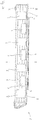
- the Fig. 1a and 1b show a rail vehicle car body 1, the Fig. 1a a view from diagonally above and the Figure 1b shows a view from the side.
- the car body has a head structure which is arranged in the illustration at the right end of the car body and the eye falls on the right side wall 2 in both illustrations.
- the car body has a horizontally running car body roof 3 as a second roof section (flat roof) at the front and rear end ) on. In between there is a curved car body roof 4 (contour roof) as the first roof section. They also show Fig. 1a and 1b Window cutouts 5 and door cutouts 6 in the side wall. An opening 7 is present between the contour roof 4 and the flat roofs 3.
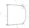
- the Fig. 2 shows a cross section through the car body of FIG Figure 1b along the line II. It is a cross section through the area of the car body in which a contour roof is arranged. Shown are the right car body side wall 2, the left car body side wall 8, the car body floor 9 and the contour roof 4.
- the longitudinal member according to the invention is arranged in the marked section X and is based on the Fig. 3 explained.
- the car body floor 9, the side walls 2, 8, the contour roof 4 and the side members are made of extruded profile parts with a hollow chamber structure.
- the Fig. 3 shows the longitudinal beam 10 according to the invention with an attached right car body side wall 2 and an attached contour roof 4.
- the longitudinal beam 10 is shown as a dark-colored hollow chamber profile to make it easier to distinguish it from adjacent components. This is only a graphic representation and does not mean that the longitudinal beam 10 has to be made of a different material than a contoured roof 4 or a side wall 2. All these parts are preferably made of aluminum.
- the longitudinal support 10, formed from a hollow chamber profile has a first projection 11 pointing obliquely upward and having a free end 12. The free end 12 forms the first attachment point for a first roof section.
- the curved car body roof 4 is welded to the free end 12. Details on the welded connection are given below in Fig. 4 described.
- the longitudinal member 10 has a second projection 13 with a free end 14.
- the free end 14 forms the second attachment point for a second roof section.
- the second projection 13 points horizontally in the direction of the inside of the car body and is arranged below the first projection 11.
- the first projection 11 is formed from a single chamber of a hollow chamber profile and it is tapered in the direction of its free end 12.
- the second projection 13 is formed from two chambers of a hollow chamber profile and tapers in the direction of its free end 14.
- the free end 14 of the second projection 13 is exposed since no flat roof is attached in this area of the car body.
- the outside of the car body is designated with the letter A and the inside of the car body with the letter B.
- the dashed line which is drawn as an extension of the side wall 2, together with the side wall of the car body, forms the boundary line between the inside of the car body B and the outside of the car body A according to the definition of this invention.
- the dashed line corresponds to an imaginary extension of the side wall 2 upwards.
- a corresponding dashed line is also in the Fig. 7 It is shown in the Fig. 3 to see that the second projection 13 protrudes over the first protrusion 11 in the horizontal direction and that it protrudes over the first protrusion in the direction of the inside B of the car body.
- a fastening means 15 in the form of a downwardly open C-rail is provided in the underside of the second projection 13.
- the C-rail is an integral part of the extruded profile.
- a lower section 16 of the longitudinal member 10 is connected to the right side wall 2 at its lower end 17, which is the third attachment point here.
- the lower section 16 has at the lower end two lips 18 which kink inward relative to one another and against which two lips 19 protruding from the end of the side wall 2 rest.
- the lips 18 and 19 are connected to one another by a welded connection, as a result of which the connection from the side wall 2 to the longitudinal beam 10 or its lower section 16 is established.
- the side wall 2 also has a fastening means 20 in the form of a C-rail.
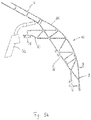
- the Fig. 4 shows an enlarged section from Fig. 3 , in which the attachment point between the first projection 11 of the longitudinal member 10 and the contoured roof 4 is shown. From the Fig. 4 it can be seen that the first projection 11 of the longitudinal member 10 has a protruding lip 30 at its free end 12 on which the contoured roof 4 is placed. At its end 31, the contour roof 4 in turn has a protruding lip 32 which lies on the first projection 11 on the outside of the car body. A gap is formed between the end 31 of the contour roof 4 and the end 12 of the longitudinal member 10 to compensate for manufacturing tolerances.
- the first projection 11 has a recess 33 at the contact point with the lip 32, into which the lip 32 is fitted in order to create a flush transition from the contoured roof 4 to the longitudinal member 10.
- lap welds are carried out in order to join the contoured roof 4 to the free end 12 of the first projection 11 of the longitudinal member 10.
- the creation of such a weld joint is in the Figure 5a and 5b shown.
- the extension of the longitudinal member 10 in the longitudinal direction of the car body is shown in detail, in addition to a section through the longitudinal member 10 and a side wall 2 in the transverse direction.
- the Figure 5b shows only a cross-section.
- the longitudinal member 10 is in one piece or in one piece, ie it extends seamlessly from one end of the car body, which is in the Figure 5a can be seen at the right edge of the picture, to the other end of the car body, which in the view of the Figure 5a is on the left, but is no longer shown in the figure itself.
- the longitudinal beam 10 is arranged in the transition area from the side wall 2 to the roof 4 and is also referred to as the top flange.
- the welding accessibility of the first projection 11 to create a welded connection to the contoured roof 4 is shown.
- the welding torch 50 can be applied from the inside of the car body to create a weld seam.
- the welding technology accessibility to the first projection 11 is given without the second projection 13 having to be separated. If necessary, the welding torch 50 can even be leaned against the second projection 13 and in the longitudinal direction of the car body (in the direction of view of the observer at Figure 5b ) are guided along the second projection 13.
- the Fig. 6 shows a section through a car body 1 along that in FIG Figure 1b shown line II-II. It is a section through an area of the car body 1 in which a flat roof 3 is attached.
- the longitudinal beam 10 according to the invention connects the car body side walls 2, 8 with the flat roof 3. Otherwise, for further explanation of the figure, refer to the explanations for Fig. 2 Be referred to.
- the Fig. 7 shows the section Y from the Fig. 6 in enlargement.
- a side wall 2 is attached to the third end 17, which is the third attachment point here, of the lower section 16, and a flat roof 3 is attached to the free end 14 of the second projection 13.
- the free end 12 of the first projection 11 is exposed and the projection 11 also remains in the flat roof area on the car body.
- the projection 11 protrudes above the level of the flat roof 3 and can serve as a lateral shield for devices (not shown here) attached to the flat roof, such as air conditioning systems.
- the projection can cover the device completely or partially to the outside of the car body A when viewed from the side (from left to right in the picture).
- the Fig. 8 shows an enlarged section from Fig. 7 , in which the connection point from the flat roof 3 to the second projection 13 of the side member 10 is shown in detail.
- the second projection 13 has at its end 14 a protruding lip 40 on which the contour roof 3 is placed. At its end 41, the contour roof 3 has a lip 42 which rests on the second projection 13.
- the second projection 13 has a recess 43 into which the lip 42 of the flat roof 3 fits.
- the free-standing first projection 11 can serve as a guide for a welding torch 50.
- the welding torch 50 is guided along the projection 11 in the longitudinal direction of the car (viewing direction of the observer) in order to create a welded connection between the flat roof 3 and the second projection 13.
- the burner tube 51 of the welding torch 50 is leaned against the edge of the protruding lip 30 at the free end 12 of the first projection 11 and the opening 52 of the burner tube 51 is aligned with the free end 14 of the second projection 13.
- the welding torch By guiding the welding torch along the end of the lip 30 at the free end 12 of the first projection 11 in the longitudinal direction of the carriage, the welding torch remains at the optimum angle, which is around 45 ° here, to create an overlap weld between the flat roof 3 and the second projection 13 aligned.
- the burner nozzle 51 rests on the end of the lip 30.
- the length of the first projection 11, including the lip 30, and the length of the second projection 13 are dimensioned such that an imaginary connecting line from the end of the lip 30 to the free end 14 of the second projection 13 with the horizontal (here for example, the roof line of the flat roof 3) forms an angle of about 45 °.
- the outermost point of the projection 11 is the end 35 of the lip 30.
- the end 12 of the first projection 11 If no lip 30 is provided at the free end 12 of the first projection 11, the end 12, here in the form of a final profile web, itself forms the outermost point and the support point for the Burner nozzle 51.
- the first projection 11 would ideally be dimensioned such that an imaginary connecting line from the free end 12 to the free end 14 forms an angle of 45 ° with the horizontal.
- the Fig. 9 also shows the very good welding accessibility of the connection point from the flat roof 3 to the second projection 13 of the side member, because the second projection 13 protrudes over the first projection 11 in the horizontal direction (horizontally to the left in this illustration).
- Fig. 10 shows the drainage of a flat roof area 3.
- the first projection 11 of a side member 10 has a drainage channel in its interior.
- the first projection 11 is formed from a single chamber of a hollow chamber profile, as for example in FIG Fig. 3 and 4th shown, and this hollow chamber serves as a drainage channel.
- the drainage channel extends in the longitudinal direction of the car and only along part of the projection 11.
- the drainage channel runs from an inflow opening 60 to an outflow opening 61.
- the inflow opening 60 is accessible from a flat roof section 3.
- In the area of the inflow opening are the walls of the hollow profile chamber of the first projection 11 partially removed, whereby a drain niche was created. Areas of the profile hollow chamber of the first projection 11 in which no drainage channel is provided are closed with a plate 64.
- the discharge opening 61 is arranged in the lower area of the hollow profile chamber of the first projection 11 and it is located at the bottom at the longitudinal end 63 of the projection 11 and thus at the end of the car body 1.
- the profile chamber of the first projection is closed at the longitudinal end 63 by a plate 65, so that water flowing off is drained off exclusively through the drain opening 61 pointing downwards. In principle, it would also be conceivable to leave the profile chamber of the first projection open at the side and to drain water through this opening.
- a pipe socket 62 is welded to the first projection 11 at the outflow opening 61. Further piping can be connected to the pipe socket 62 in order to divert draining water specifically to certain positions on the underframe (not shown) of the car body 1, for example to the center of the track bed.
- the direction of flow of the water running off the flat roof section 3 is indicated by arrows. As can be seen from the arrows, water is directed from the flat roof to the end of the car.
Landscapes
- Engineering & Computer Science (AREA)
- Life Sciences & Earth Sciences (AREA)
- Wood Science & Technology (AREA)
- Mechanical Engineering (AREA)
- Body Structure For Vehicles (AREA)
- Butt Welding And Welding Of Specific Article (AREA)
- Train Traffic Observation, Control, And Security (AREA)
- Tires In General (AREA)
Description
- Die Erfindung betrifft einen Wagenkasten eines Schienenfahrzeugs mit einem Längsträger für den Übergangsbereich einer Wagenkastenseitenwand zum Wagenkastendach eines Schienenfahrzeug-Wagenkastens, wobei an den Längsträger in einfacher Weise verschiedene Wagenkastendachabschnitte angebracht werden können, und ein Schienenfahrzeug, aufweisend einen solchen Längsträger, und auch ein Verfahren zur Herstellung eines Schienenfahrzeug-Wagenkastens mit verschiedenen Dachabschnitten.
- Schienenfahrzeug-Wagenkästen können sowohl gewölbte Dachbereiche, auch bezeichnet als Konturdachbereiche, als auch Flachdachbereiche oder weniger steil aufragende Dachbereiche aufweisen. Das Dachniveau in den Flachdachbereichen ist gegenüber dem Dachniveau in den gewölbten Dachbereichen abgesenkt. Auf den Flachdachabschnitten sind beispielsweise Klimaanlagen, Dachstromabnehmer Energiespeicher oder Antriebseinrichtungen angeordnet. Durch die Anordnung solcher Einrichtungen auf Flachdachbereichen wird vermieden, dass diese Einrichtungen über das Höhenniveau der gewölbten Dachabschnitte herausragen, oder es wird zumindest erreicht, dass sie weniger weit herausragen.
- Die Flachdachbereiche bei Wagenkästen wurden bisher beispielsweise mit einer Dachwanne realisiert. Eine solche Dachwanne weist einen horizontalen oder einen im Wesentlichen horizontalen Boden auf, der die Dachfläche bildet, und ansteigende Seitenwände. Eine Dachwanne kann mit einem Konturdach verbunden werden. Beispielsweise wird in einem Konturdach eine rechteckige Öffnung geschaffen, in welche eine Dachwanne eingeschweißt wird.
-
EP 1839989 A2 beschreibt einen Wagenkasten für Schienenfahrzeuge mit einem abgesenkten Flachdachbereich. Zum Einsetzen eines solchen Flachdachbereiches wird ein seitlicher Konstruktionskörper, der am oberen Ende der Seitenwand angeordnet ist, abgeschnitten, um eine Ansatzstelle für einen wannenförmigen abgesenkten Flachdachbereich zu schaffen. Der Nachteil einer solchen Lösung liegt darin, dass ein Teil des seitlichen Konstruktionskörpers abgetrennt werden muss, um eine Ansatzstelle zum Anfügen eines Flachdachbereiches zugänglich zu machen. - Ein Wagenkasten gemäß der ersten Alternative des Oberbegriffs des unabhängigen Anspruchs 1 ist bekannt aus
EP 0 622 285 A1 . - Jürgen Schnaas in ZEV + DET Glas, Ann. 123 (1999) 7/8 Juli/August offenbart einen Obergurt für eine Straßenbahn. Er besteht aus zwei automatisch verschweißten Profilen, in denen unterschiedliche Funktionen integriert sind, wie z.B. Regenrinne. Befestigungsmöglichkeiten für Türantriebe und Kabelkanäle, sowie Abdicht- und Klebeflächen für das Dach, das aus einem Aluminium Hartschaum-Sandwich hergestellt ist.
-
CN 2839055Y offenbart: Eine Fahrzeugkarosseriekontruktion, welche umfasst: ein Fahrzeugdach, an beiden Seiten befindliche Fahrzeugfenster sowie eine untere Wandplatte, wobei zwischen den Fahrzeugfenstern und dem Fahrzeugdach ein Fahrzeugdachseitenbalken vorgesehen ist. Unterhalb des Fahrzeudaches ist ein flaches Oberteil zur Montage des Klimatisierungsaggregats vorgesehen. An dem unteren Teil der Fahrzeugkarosserie ist außerdem ein Bodengestell-Randbalken, ein Bodengestell-Mittelbalken und eine Bodenplatte vorgesehen. Der Fahrzeugdach-Seitenbalken, die untere Wandplatte, der Bodengestell-Randbalken und der Bodengestell- Mittelbalken sind aus Aluminiummaterial hergestellt. Bei zumindest einer der Komponenten von vorstehend bezeichnetem Fahrzeugdach, flachem Oberteil und Bodenplatte handelt es sich um Aluminium-Waben-Verbundplatten. -
US 4,377,058 offenbart eine gebogene Dachkonstruktion für ein Schienenfahrzeug, bei der sich mehrere Dachstützstege quer zwischen gegenüberliegenden Wagenseitenwänden in voneinander beabstandeten Abständen erstrecken. Diese Stege bieten Unterstützung für eine Vielzahl von großen Dachplatten, die im Allgemeinen in einer End-zu-End-Beziehung angeordnet sind und die Dachfläche definieren. Die Stützstege weisen nach außen gekrümmte oder gebogene Formen zwischen ihren gegenüberliegenden Enden auf, so dass die Dachplatten ähnlich gebogen werden. - Eine Aufgabe der vorliegenden Erfindung besteht darin, das Befestigen unterschiedlicher Dachbereiche mit einer unterschiedlichen Höhe zu erleichtern, und insbesondere das Befestigen von Flachdachbereichen zu erleichtern.
- Als Lösung schlägt die Erfindung einen Wagenkasten vor, wie in den beigefügten Patentansprüchen angegeben. Besonders vorteilhafte Ausführungsformen des Wagenkastens sind in den Unteransprüchen angegeben. Ebenfalls angegeben wird ein Schienenfahrzeug-Wagenkasten mit unterschiedlich hohen Dachbereichen und ein Verfahren zur Herstellung eines solchen Schienenfahrzeug-Wagenkastens.
- Die Erfindung betrifft einen Wagenkasten mit einem Längsträger oder alternativ einer nach Anspruch 1.
- Im Sprachgebrauch dieser Beschreibung entspricht die "Wagenkasteninnenseite" der Wagenkasteninnenseite einer Seitenwand oder einer gedachten Verlängerung einer Seitenwand nach oben. Der Begriff "in Richtung Wagenkasteninnenseite" bedeutet nicht zwingend, dass eine Ansatzstelle oder ein nachfolgend noch beschriebener Vorsprung in den Innenraum des Wagenkastens zeigt, denn dies ist zumindest nicht der Fall, wenn an die Ansatzstelle oder den Vorsprung ein Dachabschnitt angesetzt ist. Der Begriff "in Richtung Wagenkasteninnenseite" bedeutet also nicht zwingend "in Richtung Wageninnenraum". Zur Verdeutlichung dienen die folgenden Beispiele: Ist der Längsträger über einer in Fahrtrichtung rechten Seitenwand angeordnet, so bedeutet der Begriff "in Richtung Wagenkasteninnenseite", dass die zweite Ansatzstelle in Fahrtrichtung nach links weist. Ist der Längsträger über einer in Fahrtrichtung linken Seitenwand angeordnet, so bedeutet der Begriff "in Richtung Wagenkasteninnenseite", dass die zweite Ansatzstelle in Fahrtrichtung nach rechts weist. Entsprechendes gilt für eine erste Ansatzstelle oder einen (nachfolgend beschriebenen) ersten oder zweiten Vorsprung, sofern diese in ihrer Ausrichtung mit Bezug auf eine Wagenkasteninnenseite definiert sind. Eine weitere Erläuterung der Wagenkasteninnenseite und Wagenkastenausßenseite wird in der Figurenbeschreibung gegeben.
- Der Längsträger ist ein tragendes Element des Wagenkastens und verläuft in Wagenlängsrichtung zwischen Seitenwand und Dach. Anders ausgedrückt ist er im Übergangsbereich von der Seitenwand zum Dach angeordnet. Ein erfindungsgemäßer Träger wird auch als Obergurt bezeichnet. Der Längsträger kann ein Teil eines Wagenkastens in Integralbauweise sein bzw. für einen Wagenkasten in Integralbauweise bestimmt sein.
- Nach einer grundlegenden Idee der Erfindung weist der Längsträger eine Ansatzstelle auf, an der ein erster Dachabschnitt angesetzt und angebracht werden kann, beispielsweise ein nach oben gewölbter Dachabschnitt, und eine weitere Ansatzstelle, an der ein zweiter Dachabschnitt, beispielsweise ein Flachdachabschnitt angesetzt und angebracht werden kann. Dadurch können je nach Bedarf an den Längsträger verschiedene Dachabschnitte angebracht werden und innerhalb des gleichen Schienenfahrzeugwagens werden abwechselnd verschiedene Dachabschnitte geschaffen. Mit dem "ersten Dachabschnitt" und dem "zweiten Dachabschnitt" sind verschiedene Dachtypen gemeint, die in Wagenlängsrichtung aufeinander folgend am Längsträger angeordnet werden können. Der Unterschied zwischen dem erwähnten ersten Dachabschnitt und dem erwähnten zweiten Dachabschnitt besteht insbesondere darin, dass der erste Dachabschnitt nach oben über den zweiten Dachabschnitt hinausragt. Dies bedeutet insbesondere, dass der erste Dachabschnitt an seinem höchsten Punkt höher ist als der zweite Dachabschnitt. Ein weiterer Unterschied besteht darin, dass vorzugsweise nur der zweite Dachabschnitt zur Anbringung von Vorrichtungen, beispielsweise Klimaanlagen, Energiespeichern, Antriebseinrichtungen oder Dachstromabnehmern, vorgesehen ist, nicht jedoch der erste Dachabschnitt. Die Querschnittform eines Daches oder eines Dachabschnitts kann in seinem Verlauf in Wagenlängsrichtung variieren.
- Wenn der Längsträger in den Wagenkasten eingebaut ist, so erstreckt er sich in Längsrichtung des Wagenkastens, und vorzugsweise über die gesamte Länge des Wagenkastens. Die genannten Ansatzstellen für die Seitenwand und die ersten und zweiten Dachabschnitte erstrecken sich über die gesamte Länge des Trägers, vorzugsweise über die gesamte Länge des Wagenkastens. Insbesondere ist die Querschnittsform des Längsträgers über die gesamte Länge im Wesentlichen gleich. Die Oberflächen, die die Ansatzstellen definieren, weisen daher insbesondere über die gesamte Länge die gleiche Breite und ggf. das gleiche Querschnittsprofil auf.
- Der erfindungsgemäße Längsträger ist einstückig gefertigt, beispielsweise als Strangpressprofil, und erstreckt sich in Wagenkastenlängsrichtung vorzugsweise vom vorderen Ende des Wagenkastens bis zum hinteren Ende des Wagenkastens. Besonders bevorzugt ist der Längsträger ein Strangpressprofil aus Metall, besonders bevorzugt aus Aluminium oder einer Aluminiumlegierung. Besonders bevorzugt ist der Längsträger ein extrudiertes Profil mit einer Hohlkammerstruktur, insbesondere aus Aluminium, wobei die Kammern durch in Längsrichtung verlaufende Wände getrennt sein können.
- Der Vorteil des erfindungsgemäßen Längsträgers liegt darin, dass an ihm zur Anbringung verschiedener Dachabschnitte keine mechanische Bearbeitung vorgenommen werden muss. Über seine gesamte Länge, vorzugsweise die gesamte Wagenlänge, kann der Längsträger gleich gestaltet sein und auch gleich gestaltet bleiben, unabhängig davon, ob an ihm ein erster oder ein zweiter Dachabschnitt angebracht ist oder wird. Es stehen die vorhandenen, wahlweise die erste und zweite Ansatzstelle zur Verfügung. Nach Anbringen eines ersten Dachabschnitts an der ersten Ansatzstelle kann die nicht genutzte zweite Ansatzstelle in diesem Abschnitt am Träger verbleiben, und nach Anbringen eines zweiten Dachabschnitts an der zweiten Ansatzstelle kann die nicht genutzte erste Ansatzstelle in diesem Abschnitt am Träger verbleiben.
- An der nach unten oder schräg nach unten zeigenden dritten Ansatzstelle kann eine Wagenkastenseitenwand an den Längsträger angesetzt und mit dem Längsträger verbunden werden. Ein erfindungsgemäßer Längsträger wird insbesondere sowohl über der in Fahrtrichtung rechten als auch der in Fahrtrichtung linken Seitenwand eines Wagenkastens angeordnet. Die Längsträger sind spiegelbildlich zueinander angeordnet, bezogen auf eine zwischen den Seitenwänden angeordnete Symmetrieebene. Die verschiedenen Dachabschnitte erstrecken sich insbesondere jeweils von Längsträger zu Längsträger und überspannen damit den Zwischenraum zwischen den Seitenwänden. Im fertiggestellten Wagenkasten sind die Längsträger im Übergangsbereich von Seitenwand zum Dach des Wagenkastens angeordnet.
- Querversteifungselemente, die sich jeweils guer durch den Wagenkasten erstrecken und an der zweiten Ansatzstelle eines Längsträgers und der zweiten Ansatzstelle eines weiteren Längsträgers auf der anderen Seite des Wagenkastens befestigt sind, sind beispielsweise an Stellen des Wagenkastens anbringbar, beispielsweise durch Schweißen, an denen sich ein erster Dachabschnitt befindet und an denen die zweiten Ansatzstellen der Längsträger zu beiden Seiten (rechts und links) des Wagenkastens nicht zur Anbringung eines zweiten Dachabschnittes genutzt sind. Ein Querversteifungselement erstreckt sich in diesem Fall unterhalb eines ersten Dachabschnitts von der zweiten Ansatzstelle eines Längsträgers auf der einen Seite des Wagenkastens bis zur zweiten Ansatzstelle eines Längsträgers auf der anderen Seite des Wagenkastens. Vorzugsweise besteht das Querversteifungselement aus Metall, vorzugsweise Aluminium Durch die Anbringung solcher Querversteifungselemente kann das Schwingungsverhalten des Wagenkastens verbessert werden, insbesondere bei Wagenkästen, deren andere Teile auch in Aluminium-Integralbauweise gefertigt sind.
- Vorzugsweise ist der erste Dachabschnitt ein nach oben gewölbter Dachabschnitt. Ein gewölbter Dachabschnitt wird in dieser Beschreibung auch als "Konturdach" oder "Bogendach" bezeichnet. Der Begriff "gewölbt" schließt alle denkbaren Krümmungsradien und Bogenformen ein. Auch kann der Krümmungsradius variieren und/oder kann das Querschnittsprofil abgewinkelt sein. Betrachtet man einen Wagenkasten im Querschnitt, so verläuft das Konturdach z.B. ausgehend von der rechten (oder, in umgekehrter Betrachtung, linken) Seitenwand nach oben, erreicht an einem beliebigen Punkt zwischen der rechten und der linken Seitenwand einen höchsten Punkt, einen höchsten Bereich oder höchste Punkte, und verläuft zur linken oder, in umgekehrter Betrachtung, rechten) Seitenwand hin wieder abwärts. Vorzugsweise ist das Konturdach spiegelsymmetrisch zu einer auf halber Strecke zwischen den Seitenwänden angenommenen Symmetrieebene. Auch der zweite Dachabschnitt kann ein nach oben gewölbter Dachabschnitt sein, der aber insbesondere den zweiten Dachabschnitt nicht nach oben überragt.
- In einer weiteren Variante ist der erste Dachabschnitt ein Dachabschnitt mit einem horizontal verlaufenden Plateau, das höher angeordnet ist als die Seitenränder des ersten Dachabschnitts, die mit der ersten Ansatzstelle verbunden sind. Auch der zweite Dachabschnitt kann ein horizontal verlaufenden Plateau aufweisen, das höher angeordnet ist als die Seitenränder des zweiten Dachabschnitts, die an der zweiten Ansatzstelle angebracht sind, solange der erste Dachabschnitt den zweiten Dachabschnitt nach oben überragt.
- Vorzugsweise ist der zweite Dachabschnitt ein horizontal oder im Wesentlichen horizontal verlaufender Dachabschnitt. Ein solcher Dachabschnitt wird in dieser Beschreibung auch als "Flachdach" bezeichnet. Betrachtet man einen Wagenkasten im Querschnitt, so verläuft das Flachdach zwischen der rechten und linken Seitenwand horizontal oder im Wesentlichen horizontal. Das an den zweiten Vorsprung des Längsträgers angebrachte Flachdach muss nicht in jedem Fall exakt horizontal verlaufen, was mit dem Begriff "im Wesentlichen" ausgedrückt ist. Ein solches Dach kann ausgehend von beiden Wagenkastenseitenwänden in Richtung Wagenkastenmitte einen leichten Neigungswinkel, insbesondere von zu 5° zur Horizontalen aufweisen, wobei das Dach von beiden Wagenkastenseitenwänden aus nach oben oder von beiden Wagenkastenseitenwänden aus nach unten abgewinkelt sein kann. Die abgewinkelten Dachbereiche eines solchen zweiten Dachabschnitts treffen bei gleichem Neigungswinkel in der Mitte des Wagenkastens aufeinander.
- Am meisten bevorzugt ist der zweite Dachabschnitt ein horizontal verlaufendes Flachdach, das auf der kürzesten Strecke von der zweiten Ansatzstelle eines Längsträgers auf der einen Seite des Wagenkastens (beispielsweise der linken Seite des Wagenkastens) zur zweiten Ansatzstelle eines Längsträgers auf der anderen Seite des Wagenkastens (beispielsweise der rechten Seite des Wagenkastens) verläuft.
- Die Verbindungen zwischen den Dachabschnitten und dem Längsträger sowie der Seitenwand und dem Längsträger sind vorzugsweise Fügeverbindungen, die ein Erwärmen der zu fügenden Teile erfordern. Am meisten bevorzugt ist eine Schweiß- oder Lötverbindung. Denkbar sind prinzipiell aber auch andere Fügetechniken, wie beispielsweise Kleben oder Nieten.
- Die Ansatzstellen des Längsträgers weisen vorzugsweise profilierte Oberflächen auf, an denen die vorgesehenen Dachanschnitte des Wagenkastens angesetzt werden können. Ein Bespiel ist eine vorspringende Lippe. Im Fall der ersten Ansatzstelle dient die profilierte Oberfläche zum Ansetzen eines ersten Dachabschnitts. Im Fall der zweiten Ansatzstelle dient die profilierte Oberfläche zum Ansetzen eines zweiten Dachabschnitts. Dachabschnitte können an ihrem Rand ebenfalls eine profilierte Oberfläche aufweisen, die zu einer profilierten Oberfläche an einer Ansatzstelle in ihrer Form komplementär ist. Nach Ansetzen eines Dachabschnitts an die Ansatzstellen kann eine Fügeverbindung zwischen dem Längsträger und dem Dachabschnitt hergestellt werden, vorzugsweise eine Schweißverbindung.
- In einer speziellen Ausführungsform weist die erste Ansatzstelle eine hervorstehende Lippe auf, auf die ein erster Dachabschnitt gelegt werden kann und die durch eine Schweißverbindung mit dem ersten Dachabschnitt verbunden werden kann. In einer anderen speziellen Ausführungsform weist die zweite Ansatzstelle eine hervorstehende Lippe auf, auf die ein zweiter Dachabschnitt gelegt werden kann und die durch eine Schweißverbindung mit dem zweiten Dachabschnitt verbunden werden kann.
- Die Vorsprünge und der untere Abschnitt erstrecken sich insbesondere über die gesamte Länge des Trägers in Wagenlängsrichtung oder zumindest über einen Längsabschnitt, in dem verschiedene Dachabschnitte am Längsträger befestigt werden. Der untere Abschnitt weist im Querschnitt des Längsträgers vorzugsweise eine größere Querschnittsfläche auf als jeder der Vorsprünge. Alternativ oder zusätzlich ist die Breite des unteren Abschnitts vorzugsweise größer als die Breite der Vorsprünge. Die Breite wird in einer Richtung quer zur Längsrichtung bestimmt. Der untere Abschnitt ist im zusammengebauten Zustand des Wagenkastens über der Seitenwand angeordnet. Die Seitenwand ist an der dritten Ansatzstelle an den unteren Abschnitt angebracht. Die dritte Ansatzstelle befindet sich vorzugsweise am unteren Ende des unteren Abschnitts. Es ist auch möglich, dass Seitenwand und Längsträger ein integrales Teil bilden.
- Die Ansatzstelle für den ersten Dachabschnitt befindet sich am Ende des ersten Vorsprungs und die Ansatzstelle für den zweiten Dachabschnitt befindet sich am Ende des zweiten Vorsprungs. Dadurch kann je nach Bedarf an den ersten Vorsprung des Längsträgers ein erster Dachabschnitt angebracht werden und an den zweiten Vorsprung des Längsträgers ein zweiter Dachabschnitt, sodass verschiedene Dachabschnitte an einem Wagenkasten geschaffen werden können.
- Bei diesem speziellen Längsträger ist im Fall einer Fügeverbindung durch Schweißen die schweißtechnische Zugänglichkeit zu jedem der Vorsprünge gegeben, ohne dass der jeweils nicht benötigte Vorsprung abgetrennt werden muss. Dies bedeutet z.B., dass der zweite Vorsprung am Längsträger in einem Längsabschnitt ungenutzt bleiben kann, wenn in dem Längsabschnitt an den ersten Vorsprung ein erster Dachabschnitt angeschweißt wird und umgekehrt.
- Wenn ein zweiter Dachabschnitt anbracht wird, verbleibt somit insbesondere der senkrecht nach oben oder schräg nach oben zeigende erste Vorsprung des Längsträgers stehen. Er kann als seitliche Abschirmung für auf dem zweiten Dachabschnitt angebrachte Vorrichtungen, beispielsweise Klimaanlagen, Energiespeicher, Antriebseinrichtungen oder Dachstromabnehmer, dienen und solche Vorrichtungen oder deren Befestigungsstellen ganz oder teilweise verdecken. Neben einer Abschirmung gegen Einwirkungen von der Seite, wie beispielsweise Staub und Dreck, kann der erste Vorsprung auch die Funktion eines Sichtschutzes ausüben. Wenn die optische Verkleidung oder Abschirmung von Vorrichtungen auf einem zweiten Dachabschnitt nicht erforderlich ist, kann der erste Vorsprung auch selbst als Befestigungsstelle für Vorrichtungen dienen.
- Außerdem kann der erste Vorsprung im Bereich eines zweiten Dachabschnitts, insbesondere im Bereich eines Flachdachabschnitts als seitliche Dachbegrenzung dienen, die einen Übertritt von Wasser über die Dachkante verhindert. So kann der erste Vorsprung im Bereich eines Flachdachabschnitts beispielsweise verhindern, dass Regenwasser oder Wasser aus einer auf dem Flachdach angebrachten Klimaanlage über die Seitenränder des Daches den Wagenkasten herunterläuft. Neben der Funktion als Begrenzung kann der erste Vorsprung auch selbst der Ableitung von Wasser dienen, wie weiter unten erläutert.
- Vorzugsweise ist der zuvor beschriebene speziell ausgeführte Längsträger ein Strangpressprofil aus Metall, besonders bevorzugt aus Aluminium. Besonders bevorzugt ist der Längsträger ein extrudiertes Profil mit einer Hohlkammerstruktur, insbesondere aus Aluminium. Vorzugsweise kann ein solches Profil einen äußeren (in Bezug auf das Innere des Wagenkastens) und einen inneren plattenförmigen Bereich aufweisen, die durch zusätzliche Kammerwände verbunden sind. Jeder Vorsprung sowie der untere Abschnitt des erfindungsgemäßen Längsträgers kann einen äußeren und einen inneren plattenförmigen Bereich aufweisen, die durch zusätzliche Kammerwände miteinander verbunden sind. Ebenso können die Vorsprünge aber auch aus einer einzigen Kammer eines Hohlkammerprofils gebildet sein. An ihrem Ende sind die Vorsprünge vorzugsweise geschlossen, beispielsweise durch eine Querwand.
- In einer speziellen Ausführungsform des Längsträgers weist der erste Vorsprung in seinem Inneren einen Entwässerungskanal auf. Der Entwässerungskanal dient der Ableitung von Wasser von einem Dachabschnitt, vorzugsweise von einem zweiten Dachabschnitt. Vorzugweise erstreckt sich der Entwässerungskanal in Wagenlängsrichtung. Ein sich in Wagenlängsrichtung erstreckender Entwässerungskanal kann sich über die gesamte Länge des ersten Vorsprungs erstrecken oder nur entlang eines Teiles des Vorsprungs. Der erste Vorsprung weist mindestens eine Zuflussöffnung und mindestens eine Abflussöffnung auf, zwischen denen sich der Entwässerungskanal erstreckt. Die Zuflussöffnung(en) ist vom zweiten Dachabschnitt aus zugänglich, beispielsweise indem sie auf der Seite des Vorsprungs angeordnet ist, die dem zweiten Dachabschnitt zugewandt ist. Die Abflussöffnung kann an verschiedenen Stellen angeordnet sein, beispielsweise an einem längsseitigen Ende des Vorsprungs, welches am in Fahrtrichtung vorderen Ende oder am hinteren Ende eines Wagenkastens angeordnet ist. An der Abflussöffnung kann ein Stutzen oder ein Abflussrohr angebracht sein.
- Die soeben beschriebene Ausführungsform ist besonders vorteilhaft mit einer Ausführungsform kombinierbar, bei der der erste Vorsprung aus einer oder mehreren Kammern eines Hohlkammerprofils gebildet ist. Dann dient eine solche Kammer als Entwässerungskanal.
- Die Dimensionierung der Vorsprünge kann grundsätzlich frei gewählt werden.
- Die Länge eines Vorsprungs wird durch die Länge des Längsträgers in Wagenlängsrichtung definiert. Die Tiefe eines Vorsprungs entspricht seiner Erstreckung von einer Basis des Längsträgers, im speziellen vom unteren Abschnitt, bis zu seinem freistehenden Ende.
- In einer Querschnittsansicht (quer zur Längsrichtung des Wagenkastens) durch den Längsträger betrachtet kann das Verhältnis der Breite zur Tiefe der Vorsprünge unabhängig voneinander, größer als 1 sein oder es kann kleiner als 1 sein. Die Breite eines Vorsprungs kann in Tiefenrichtung variieren. Beispielsweise kann sich zumindest einer der Vorsprünge in Richtung seines freien Endes verjüngen.
- An ihren Enden weisen die Vorsprünge vorzugsweise eine profilierte Oberfläche auf, an welcher die dafür vorgesehenen Bauteile des Wagenkastens angesetzt werden können. Im Fall des ersten Vorsprungs dient die profilierte Oberfläche zum Ansetzen eines ersten Dachabschnitts. Im Fall des zweiten Vorsprungs dient die profilierte Oberfläche zum Ansetzen eines zweiten Dachabschnitts. Die Dachabschnitte können an ihrem Rand eine profilierte Oberfläche aufweisen, die zu einer profilierten Oberfläche am Ende eines zugehörigen Vorsprungs in ihrer Form komplementär ist. Nach Ansetzen eines Dachelements kann eine Fügeverbindung zwischen dem Ende des betreffenden Vorsprungs und dem Dachelement hergestellt werden, vorzugsweise eine Schweißverbindung.
- In einer speziellen Ausführungsform weist der erste Vorsprung an seinem freien Ende eine hervorstehende Lippe auf, auf die ein erster Dachabschnitt gelegt werden kann und die durch eine Schweißverbindung mit dem ersten Dachabschnitt verbunden werden kann. Bei dieser Ausführungsform weist vorzugsweise auch der erste Dachabschnitt an seinem Ende, welches mit dem freien Ende des ersten Vorsprungs verbunden wird, eine hervorstehende Lippe auf, die beim Auflegen des Dachabschnitts auf die Lippe des Vorsprungs auf den ersten Vorsprung gelegt wird, und die ihrerseits über eine Schweißverbindung an den ersten Vorsprung gefügt werden kann. Zur Schaffung einer ebenen Verbindungsstelle kann der erste Vorsprung an der Kontaktstelle zur aufliegenden Lippe des ersten Dachabschnitts eine Vertiefung aufweisen, in welche die Lippe des ersten Dachabschnitts eingelegt wird und sich einpasst.
- In einer anderen speziellen Ausführungsform weist der zweite Vorsprung an seinem freien Ende eine hervorstehende Lippe auf, auf die ein zweiter Dachabschnitt gelegt werden kann und die durch eine Schweißverbindung mit dem zweiten Dachabschnitt verbunden werden kann. Bei dieser Ausführungsform weist vorzugsweise auch der zweite Dachabschnitt an seinem Ende, welches mit dem freien Ende des zweiten Vorsprungs verbunden wird, eine hervorstehende Lippe auf, die beim Auflegen des Dachabschnitts auf die Lippe des Vorsprungs auf den zweiten Vorsprung gelegt wird, und die ihrerseits über eine Schweißverbindung an den zweiten Vorsprung gefügt werden kann. Zur Schaffung einer ebenen Verbindungsstelle kann der zweite Vorsprung an der Kontaktstelle zur aufliegenden Lippe des zweiten Dachabschnitts eine Vertiefung aufweisen, in welche sich die Lippe des zweiten Dachabschnitts einpasst.
- Der untere Abschnitt des Längsträgers kann bei der dritten Ansatzstelle beispielsweise zwei gegenüberliegende, zur Innenseite des unteren Abschnitts zueinander abknickende Lippen aufweisen, an denen zwei vom Ende eines Seitenwandelements hervorstehende Lippen anliegen und wobei an den Übergangsstellen der aneinander anliegenden Lippen eine Schweißverbindung zwischen der Seitenwand und dem Längsträger ausgeführt werden kann.
- Der erste Vorsprung des Längsträgers kann senkrecht nach oben oder schräg nach oben verlaufen. "Schräg nach oben" bedeutet, dass der erste Vorsprung im Querschnitt (quer zur Längsrichtung des Wagenkastens) zur Wageninnenseite hin ansteigt. Der erste Vorsprung kann in gerader Richtung oder gekrümmt zu seinem freien Ende verlaufen. Der Vorsprung kann auch auf einer Seite (innen oder außen) gerade und auf der anderen Seite (innen oder außen) gekrümmt sein. Die Krümmung kann an die Krümmung des Konturdachs anschließen. Besonders bevorzugt erstreckt sich der erste Vorsprung schräg nach oben.
- Ein bevorzugter Winkel der geradlinigen Erstreckung des ersten Vorsprungs zu einer gedachten horizontalen Linie beträgt insbesondere 20° bis 70°. An einem schräg nach oben verlaufenden Vorsprung ist vorteilhaft ein erster Dachabschnitt anbringbar, der an seinen seitlichen Enden schräg nach unten verläuft. Insbesondere sind der Winkel des schräg noch oben verlaufenden ersten Vorsprungs und der Winkel des Verlaufs des Dachabschnitts an seinem Ende jeweils zur Horizontalen identisch.
- Der zweite Vorsprung weist zur Wagenkasteninnenseite. Er verläuft im Querschnitt (quer zur Längsrichtung des Wagenkastens) vorzugsweise horizontal oder im Wesentlichen horizontal. Der zweite Vorsprung kann gerade oder gekrümmt zu seinem freien Ende verlaufen, wobei die gerade Form bevorzugt ist. Im Wesentlichen horizontal bedeutet mit Bezug auf den zweiten Vorsprung, dass er zu einer gedachten horizontalen Linie um bis zu 10° nach oben ansteigend oder um bis zu 10° nach unten abfallend verlaufen kann.
- Erfindungsgemäß ragt der zweite Vorsprung über den ersten Vorsprung in horizontaler Richtung in Richtung Wagenkasteninnenseite hinaus. Dies bedeutet anders ausgedrückt, dass von oben auf den längsträger gesehen das freie Ende des zweiten Vorsprungs sichtbar ist und nicht vom ersten Vorsprung verdeckt wird. Hieibei ist eine besonders gute schweißtechnische Zugänglichkeit des zweiten Vorsprungs von oben gegeben, denn die Schweißstelle wird nicht durch den ersten Vorsprung verdeckt.
- In einer speziellen Variante sind im Querschnitt betrachtet die Tiefe des ersten Vorsprungs und die Tiefe des zweiten Vorsprungs so bemessen, dass eine gedachte Verbindungslinie vom freien Ende des ersten Vorsprungs zum freien Ende des zweiten Vorsprungs mit der Horizontalen einen Winkel von 40° bis 50° bildet. Das freie Ende ist im Fall einer vorspringenden Lippe durch deren freies Ende definiert. Andernfalls befindet sich am freien Ende z.B. eine Außenwand eines Hohlkammerprofils.
- Der Vorteil dieser Ausführungsform liegt darin, dass das freie Ende des ersten Vorsprungs als Führung für einen Schweißbrenner genutzt werden kann, wenn an den zweiten Vorsprung ein zweiter Dachabschnitt angeschweißt wird. Der Schweißbrenner, insbesondere sein Brennerohr, wird dabei an dem freien Ende des ersten Vorsprungs abgestützt oder angelehnt und die Brenneröffnung des Schweißbrenners auf das freie Ende des zweiten Vorsprungs ausgerichtet, an welchem der anzufügende zweite Dachabschnitt anliegt. Ein so ausgerichteter Schweißbrenner kann in Wagenlängsrichtung am freien Ende des ersten Vorsprungs entlanggeführt werden und eine Schweißnaht zwischen dem freien Ende des zweiten Vorsprungs und dem anliegenden Flachdachteil kann erzeugt werden. Bei diesem Vorgang bleibt der Schweißbrenner optimal ausgerichtet, insbesondere optimal zur Schaffung einer Überlappnaht zwischen zweitem Vorsprung und dem zweiten Dachabschnitt.
- In noch einer Ausführungsform weist der zweite Vorsprung des Längsträgers an seiner Unterseite ein Befestigungsmittel zur Befestigung einer Innenverkleidung oder anderweitiger Bauteile oder Baugruppen auf. In dieser Ausführungsform hat der zweite Vorsprung des Längsträgers eine Doppelfunktion, nämlich die Funktion als Anschlussstelle für einen zweiten Dachabschnitt und die Funktion einer Befestigungsstelle, z.B. für eine Innenverkleidung, beispielsweise Innenraumdecken, oder anderweitige Bauteile, wie z.B. Kabelkanäle und Elemente von Klimaanlagen.
- Ein bevorzugtes Beispiel für ein Befestigungsmittel ist eine Befestigungsschiene, insbesondere eine C-Profil-Schiene. Das Befestigungsmittel kann ein am zweiten Vorsprung befestigtes Befestigungsmittel sein, oder das Befestigungsmittel kann als integraler Teil des zweiten Vorsprungs gefertigt sein, beispielsweise als Bereich des Strangpressprofils.
- Zuvor beschriebene Längsträger können mit einem oder mehreren ersten und/oder zweiten Dachabschnitten zu einem Bauteil verbunden sein, das als Montageeinheit bzw. vormontierten Baugruppe beim Bau von Wagenkästen eingesetzt wird. Somit betrifft die Erfindung auch ein Bauteil für einen Schienenfahrzeug-Wagenkasten, aufweisend oder bestehend aus zuvor beschriebenen Längsträgern und einem oder mehreren an den Längsträgern angebrachten ersten und/oder zweiten Dachabschnitten.
- Die Erfindung betrifft aber auch ein Bauteil für einen Schienenfahrzeugwagenkasten, umfassend einen zuvor beschriebenen Längsträger und eine mit dem Träger verbundene Seitenwand. Bei diesem Gegenstand ist eine Seitenwand mit einem separat hergestellten Längsträger zu einer Montageeinheit bzw. vormontierten Baugruppe verbunden.
- In noch einem weiteren Aspekt betrifft die Erfindung ein Schienenfahrzeug, das einen Wagenkasten aufweist wie zuvor beschrieben. Bevorzugte Schienenfahrzeuge sind Metros, Nahverkehrszüge, Fernverkehrszüge, Hochgeschwindigkeitszüge und Straßenbahnen. Besonders bevorzugt sind Schienenfahrzeuge in Integralbauweise.
- Die Erfindung betrifft ferner ein Verfahren zur Herstellung eines Schienenfahrzeug-Wagenkastens nach Anspruch 7.
- Eingesetzt werden kann in dem Verfahren ein Längsträger wie bereits oben beschrieben, einschließlich aller speziellen und bevorzugten Ausführungsformen. Erfindungsgemäße Längsträger können in Schritt a) des Verfahrens als Träger auf der zur Fahrtrichtung rechten und auf der linken Seite des Wagenkastens eingesetzt werden.
- In einer Variante des Verfahrens wird beim Fügen des einen oder der mehreren ersten Dachabschnitte an die erste Ansatzstelle, insbesondere an einen ersten Vorsprung, eine Fügevorrichtung, insbesondere ein Schweißbrenner, an der zweiten Ansatzstelle, insbesondere an einem zweiten Vorsprung, entlanggeführt.
- In einer weiteren Variante des Verfahrens wird beim Fügen des einen oder der mehreren zweiten Dachabschnitte an die zweite Ansatzstelle, insbesondere an einen zweiten Vorsprung, eine Fügevorrichtung, insbesondere ein Schweißbrenner, an der ersten Ansatzstelle, insbesondere an einem ersten Vorsprung, entlanggeführt.
- Der herzustellende Wagenkasten weist mindestens einen ersten Dachabschnitt und mindestens einen zweiten Dachabschnitt auf. Die Anordnung der Dachabschnitte kann prinzipiell beliebig gewählt werden und es können mehrere erste Dachabschnitte vorhanden sein, die sich mit einem zweiten oder mit mehreren zweiten Dachabschnitten abwechseln. Es ist auch möglich, zumindest einen dritten Dachabschnitt an der ersten oder zweiten Ansatzstelle mit dem Längsträger zu verbinden. In einer speziellen Ausführungsform eines Wagenkastens sind Flachdachabschnitte am vorderen und hinteren Wagenkastenende vorgesehen und dazwischen ein Konturdachabschnitt. Die Fügeschritte des Verfahrens werden vorzugsweise durch eine Fügetechnik durchgeführt, die eine Erwärmung der zu fügenden Bauteile erfordert. Besonders bevorzugt ist eine Schweißverbindung oder eine Lötverbindung. Denkbar sind aber auch Niet- oder Klebeverbindungen.
- Zwischen einem ersten Dachabschnitt und einem zweiten Dachabschnitt kann eine Öffnung vorhanden sein wenn der erste Dachabschnitt an der Übergangsstelle nicht bereits einen Giebel aufweist. In einem optionalen weiteren Schritt des Verfahrens werden Öffnungen zwischen ersten Dachabschnitten und zweiten Dachabschnitten verschlossen. Beispielsweise kann ein Giebelelement, wie beispielsweise ein Blech oder ein passend geformtes Hohlprofil, in die Öffnung eingesetzt und an der Oberkante mit dem Rand des ersten Dachabschnitts und an der Unterkante mit dem Rand des zweiten Dachabschnitts verbunden werden, vorzugsweise durch eine Fügeverbindung, insbesondere durch Schweißen.
- Ausführungsbeispiele der Erfindung werden nun unter Bezugnahme auf die beigefügten Zeichnungen beschrieben. Es zeigen:
- Fig. 1a, 1b
- den Wagenkasten eines Schienenfahrzeugs in zwei verschiedenen Perspektiven,
- Fig. 2
- einen Querschnitt durch den Wagenkasten der
Fig. 1b entlang der Linie I-I, - Fig. 3
- eine Vergrößerung des Ausschnittes X aus der
Fig. 2 , worin ein Längsträger mit einem angefügten Konturdach gezeigt ist, - Fig. 4
- einen vergrößerten Ausschnitt aus der
Fig. 3 , der den Übergang von Längsträger zum Konturdach zeigt, - Fig. 5a, 5b
- die Herstellung einer Schweißverbindung zwischen Konturdach und Längsträger,
- Fig. 6
- einen Querschnitt durch den Wagenkasten der
Fig. 1b entlang der Linie II-II, - Fig. 7
- eine Vergrößerung des Ausschnitts Y aus der
Fig. 6 , wobei ein Längsträger mit einem angefügten Flachdach gezeigt ist, - Fig. 8
- einen Ausschnitt aus der
Fig. 7 , der den Übergang von einem Längsträger zu einem Flachdach zeigt, - Fig. 9
- die Herstellung einer Schweißverbindung zwischen einem Längsträger und einem Flachdachelement,
- Fig. 10
- einen Längsträger im Bereich eines Flachdaches, wobei der erste Vorsprung einen Entwässerungskanal aufweist.
- Die
Fig. 1a und1b zeigen einen Schienenfahrzeug-Wagenkasten 1, wobei dieFig. 1a eine Ansicht von schräg oben und dieFig. 1b eine Ansicht von der Seite zeigt. Der Wagenkasten weist eine Kopfstruktur auf, die in der Abbildung am rechten Ende des Wagenkastens angeordnet ist und der Blick fällt bei beiden Abbildungen auf die rechte Seitenwand 2. Der Wagenkasten weist am vorderen und am hinteren Ende ein horizontal verlaufendes Wagenkastendach 3 als zweiten Dachabschnitt (Flachdach) auf. Dazwischen ist ein gewölbtes Wagenkastendach 4 (Konturdach) als erster Dachabschnitt angeordnet. Außerdem zeigen dieFig. 1a und1b Fensterausschnitte 5 und Türausschnitte 6 in der Seitenwand. Zwischen dem Konturdach 4 und den Flachdächern 3 ist eine Öffnung 7 vorhanden. - Die
Fig. 2 zeigt einen Querschnitt durch den Wagenkasten derFig. 1b entlang der Linie I-I. Es handelt sich um einen Querschnitt durch den Bereich des Wagenkastens, in dem ein Konturdach angeordnet ist. Gezeigt sind die rechte Wagenkastenseitenwand 2, die linke Wagenkastenseitenwand 8, der Wagenkastenboden 9 und das Konturdach 4. Der erfindungsgemäße Längsträger ist im markierten Abschnitt X angeordnet und wird anhand derFig. 3 erläutert. Der Wagenkastenboden 9, die Seitenwände 2, 8, das Konturdach 4 und der Längsträger sind aus extrudierten Profilteilen mit einer Hohlkammerstruktur gefertigt. - Die
Fig. 3 zeigt den erfindungsgemäßen Längsträger 10 mit einer angefügten rechten Wagenkastenseitenwand 2 und einem angefügten Konturdach 4. Der Längsträger 10 ist als dunkel gefärbtes Hohlkammerprofil dargestellt, um die Unterscheidung zu benachbarten Bauteilen zu erleichtern. Dies ist lediglich eine zeichnerische Darstellung und bedeutet nicht, dass der Längsträger 10 aus einem anderen Material gefertigt sein muss als ein Konturdach 4 oder eine Seitenwand 2. Vorzugsweise bestehen alle diese Teile aus Aluminium. Der Längsträger 10, gebildet aus einem Hohlkammerprofil, weist einen schräg nach oben zeigenden ersten Vorsprung 11 mit einem freien Ende 12 auf. Das freie Ende 12 bildet die erste Ansatzstelle für einen ersten Dachabschnitt. Am freien Ende 12 ist in dieser Ausführungsform das gewölbte Wagenkastendach 4 angeschweißt. Details zu der Schweißverbindung sind nachfolgend in derFig. 4 beschrieben. Außerdem weist der Längsträger 10 einen zweiten Vorsprung 13 mit einem freien Ende 14 auf. Das freie Ende 14 bildet die zweite Ansatzstelle für einen zweiten Dachabschnitt. Der zweite Vorsprung 13 weist horizontal in Richtung Wagenkasteninnenseite und ist unter dem ersten Vorsprung 11 angeordnet. Der erste Vorsprung 11 ist aus einer einzigen Kammer eines Hohlkammerprofils gebildet und er ist in Richtung seines freien Endes 12 verjüngt. Der zweite Vorsprung 13 ist aus zwei Kammern eines Hohlkammerprofils gebildet und in Richtung seines freien Endes 14 verjüngt. Das freie Ende 14 des zweiten Vorsprungs 13 liegt frei, da in diesem Bereich des Wagenkastens kein Flachdach angebracht ist. Die Wagenkastenaußenseite ist mit dem Buchstaben A und die Wagenkasteninnenseite mit dem Buchstaben B bezeichnet. Die gestrichelte Linie, die in Verlängerung der Seitenwand 2 eingezeichnet ist, bildet zusammen mit der Wagenkastenseitenwand die Grenzline zwischen Wagenkasteninnenseite B und Wagenkastenaußenseite A nach der Definition dieser Erfindung. Die gestrichelte Linie entspricht einer gedachten Verlängerung der Seitenwand 2 nach oben. Eine entsprechende gestrichelte Linie ist auch in derFig. 7 dargestellt.Es ist in derFig. 3 zu erkennen, dass der zweite Vorsprung 13 über den ersten Vorsprung 11 in horizontaler Richtung hervorsteht und dass er über den ersten Vorsprung in Richtung Wagenkasteninnenseite B hervorsteht. In der Unterseite des zweiten Vorsprungs 13 ist ein Befestigungsmittel 15 in Form einer nach unten geöffneten C-Schiene vorgesehen. Die C-Schiene ist ein integraler Bestandteil des Strangpressprofils. Ein unterer Abschnitt 16 des Längsträgers 10 ist an seinem unteren Ende 17, das hier die dritte Ansatzstelle ist, mit der rechten Seitenwand 2 verbunden. - Der untere Abschnitt 16 weist am unteren Ende zwei zueinander nach innen abknickende Lippen 18 auf, an denen zwei vom Ende der Seitenwand 2 hervorstehende Lippen 19 anliegen. Die Lippen 18 und 19 sind durch eine Schweißverbindung miteinander verbunden, wodurch die Verbindung von Seitenwand 2 zum Längsträger 10 bzw. dessen unteren Abschnitt 16 hergestellt ist. In der gezeigten Ausführungsform weist auch die Seitenwand 2 ein Befestigungsmittel 20 in Form einer C-Schiene auf.
- Die
Fig. 4 zeigt einen vergrößerten Ausschnitt aus derFig. 3 , in dem die Ansatzstelle zwischen dem ersten Vorsprung 11 des Längsträgers 10 und dem Konturdach 4 dargestellt ist. Aus derFig. 4 ist ersichtlich, dass der erste Vorsprung 11 des Längsträgers 10 an seinem freien Ende 12 eine hervorstehende Lippe 30 aufweist, auf die das Konturdach 4 gelegt ist. Das Konturdach 4 weist an seinem Ende 31 seinerseits eine hervorstehende Lippe 32 auf, die sich an der Wagenkastenaußenseite auf den ersten Vorsprung 11 legt. Zwischen dem Ende 31 des Konturdachs 4 und dem Ende 12 des Längsträgers 10 ist ein Spalt als Ausgleich für Fertigungstoleranzen gebildet. Der erste Vorsprung 11 weist an der Kontaktstelle zur Lippe 32 eine Vertiefung 33 auf, in welche die Lippe 32 zur Schaffung eines bündigen Übergangs von Konturdach 4 zu Längsträger 10 eingepasst ist. Am Ende 34 der Lippe 32 des Konturdachs und am Ende 35 der Lippe 30 des Längsträgers 10 werden Überlappschweißnähte ausgeführt, um das Konturdach 4 an das freie Ende 12 des ersten Vorsprungs 11 des Längsträgers 10 zu fügen. Die Schaffung einer solchen Schweißverbindung ist in denFig. 5a und5b gezeigt. In derFig. 5a ist ausschnittweise auch die Ausdehnung des Längsträgers 10 in Wagenkastenlängsrichtung gezeigt, zusätzlich zu einem Schnitt durch den Längsträger 10 und eine Seitenwand 2 in Querrichtung. DieFig. 5b zeigt nur einen Schnitt in Querrichtung. InFig. 5a ist erkennbar, dass der Längsträger 10 einteilig bzw. einstückig ist, d.h. er erstreckt sich nahtlos von einem Ende des Wagenkastens, welches in derFig. 5a am rechten Bildrand zu sehen ist, zum anderen Ende des Wagenkastens, das in der Ansicht derFig. 5a auf der linken Seite ist, in der Figur selbst aber nicht mehr gezeigt ist. Der Längsträger 10 ist im Übergangsbereich von der Seitenwand 2 zum Dach 4 angeordnet und wird auch als Obergurt bezeichnet. In denFig. 5a und5b ist die schweißtechnische Zugänglichkeit des ersten Vorsprungs 11 zur Schaffung einer Schweißverbindung zum Konturdach 4 gezeigt. Der Schweißbrenner 50 kann zur Schaffung einer Schweißnaht von der Innenseite des Wagenkastens angesetzt werden. Die schweißtechnische Zugänglichkeit zum ersten Vorsprung 11 ist gegeben, ohne dass der zweite Vorsprung 13 abgetrennt werden muss. Gegebenenfalls kann der Schweißbrenner 50 sogar an den zweiten Vorsprung 13 angelehnt werden und in Wagenkastenlängsrichtung (in Blickrichtung des Betrachters beiFig. 5b ) an dem zweiten Vorsprung 13 entlanggeführt werden. - Die
Fig. 6 zeigt einen Schnitt durch einen Wagenkasten 1 entlang der in derFig. 1b dargestellten Linie II-II. Es handelt sich um einen Schnitt durch einen Bereich des Wagenkastens 1, in dem ein Flachdach 3 angebracht ist. Der erfindungsgemäße Längsträger 10 verbindet die Wagenkastenseitenwände 2, 8 mit dem Flachdach 3. Ansonsten kann zur weiteren Erläuterung der Figur auf die Erläuterungen zurFig. 2 Bezug genommen werden. - Die
Fig. 7 zeigt den Ausschnitt Y aus derFig. 6 in Vergrößerung. Eine Seitenwand 2 ist an das dritte Ende 17, das hier die dritte Ansatzstelle ist, des unteren Abschnitts 16 angefügt und ein Flachdach 3 ist an das freie Ende 14 des zweiten Vorsprungs 13 angefügt. Das freie Ende 12 des ersten Vorsprungs 11 liegt frei und der Vorsprung 11 verbleibt auch im Flachdachbereich an dem Wagenkasten. Der Vorsprung 11 ragt über das Niveau des Flachdachs 3 hinaus und kann als seitliche Abschirmung für auf dem Flachdach angebrachte Vorrichtungen (hier nicht gezeigt) dienen, wie z.B. Klimaanlagen. Je nach Dimensionierung einer solchen Vorrichtung und des Vorsprungs 11 kann der Vorsprung die Vorrichtung ganz oder teilweise zur Wagenkastenaußenseite A bei seitlicher Betrachtung (im Bild von links nach rechts) verdecken. Zur Erläuterung weiterer Merkmale derFig. 7 wird auf dieFig. 3 verwiesen. - Die
Fig. 8 zeigt einen vergrößerten Ausschnitt aus derFig. 7 , in dem die Verbindungsstelle von Flachdach 3 zum zweiten Vorsprung 13 des Längsträgers 10 detailliert dargestellt ist. Der zweite Vorsprung 13 weist an seinem Ende 14 eine hervorstehende Lippe 40 auf, auf die das Konturdach 3 gelegt ist. Das Konturdach 3 weist an seinem Ende 41 eine Lippe 42 auf, die auf dem zweiten Vorsprung 13 aufliegt. Zur Schaffung einer ebenen Verbindungsstelle von Flachdach 3 zu zweitem Vorsprung 13 weist der zweite Vorsprung 13 eine Vertiefung 43 auf, in welche sich die Lippe 42 des Flachdachs 3 einpasst. Am Ende 44 der Lippe 42 und am Ende 45 der Lippe 40 werden in Wagenlängsrichtung (in dieser Darstellung in Blickrichtung des Betrachters) Überlappschweißnähte geschaffen, um das Flachdach 3 an das freie Ende 14 des Vorsprungs 13 zu fügen. - In der
Fig. 9 ist gezeigt, wie der freistehende erste Vorsprung 11 als Führung für einen Schweißbrenner 50 dienen kann. Der Schweißbrenner 50 wird in Wagenlängsrichtung (Blickrichtung des Betrachters) an dem Vorsprung 11 entlanggeführt, um eine Schweißverbindung zwischen dem Flachdach 3 und dem zweiten Vorsprung 13 zu schaffen. Das Brennerrohr 51 des Schweißbrenners 50 wird an den Rand der hervorstehenden Lippe 30 am freien Ende 12 des ersten Vorsprungs 11 angelehnt und die Öffnung 52 der Brennerrohrs 51 auf das freie Ende 14 des zweiten Vorsprungs 13 ausgerichtet. Indem man den Schweißbrenner derart am Ende der Lippe 30 am freien Ende 12 des ersten Vorsprungs 11 in Wagenlängsrichtung entlangführt, bleibt der Schweißbrenner im optimalen Winkel, der hier in etwa 45° beträgt, zur Schaffung einer Überlappschweißnaht zwischen dem Flachdach 3 und dem zweiten Vorsprung 13 ausgerichtet. In der hier gezeigten Ausführungsform liegt die Brennerdüse 51 am Ende der Lippe 30 an. In der hier gezeigten Ausführungsform ist die Länge des ersten Vorsprungs 11, inklusive Lippe 30, und die Länge des zweiten Vorsprungs 13 so bemessen, dass eine gedachte Verbindungslinie von dem Ende der Lippe 30 zum freien Ende 14 des zweiten Vorsprungs 13 mit der Horizontalen (hier beispielsweise die Dachlinie des Flachdachs 3) einen Winkel von etwa 45° bildet. Der äußerste Punkt des Vorsprungs 11 ist das Ende 35 der Lippe 30. Sofern am freien Ende 12 des ersten Vorsprungs 11 keine Lippe 30 vorgesehen ist, bildet das Ende 12, hier in Form eines abschließenden Profilsteges, selbst den äußersten Punkt und den Abstützpunkt für die Brennerdüse 51. In diesem Fall wäre der erste Vorsprung 11 idealerweise so bemessen, dass eine gedachte Verbindungslinie vom freien Ende 12 zum freien Ende 14 mit der Horizontalen einen Winkel von 45° bildet. DieFig. 9 zeigt auch die sehr gute schweißtechnische Zugänglichkeit der Verbindungsstelle von Flachdach 3 zum zweiten Vorsprung 13 des Längsträgers, weil der zweite Vorsprung 13 über den ersten Vorsprung 11 in horizontaler Richtung (in dieser Darstellung horizontal nach links) hervorsteht. -
Fig. 10 zeigt die Entwässerung eines Flachdachbereiches 3. Der erste Vorsprung 11 eines Längsträgers 10 weist in seinem Inneren einen Entwässerungskanal auf. Der erste Vorsprung 11 ist aus einer einzigen Kammer eines Hohlkammerprofils gebildet, wie z.B. inFig. 3 und4 dargestellt, und diese Hohlkammer dient als Entwässerungskanal. Der Entwässerungskanal erstreckt sich in Wagenlängsrichtung und nur entlang eines Teiles des Vorsprungs 11. Der Entwässerungskanal verläuft von einer Zuflussöffnung 60 bis zu einer Abflussöffnung 61. Die Zuflussöffnung 60 ist von einem Flachdachabschnitt 3 aus zugänglich. Im Bereich der Zuflussöffnung sind die Wände der Profilhohlkammer des ersten Vorsprungs 11 teilweise entfernt, wodurch eine Abflussnische geschaffen wurde. Bereiche der Profilhohlkammer des ersten Vorsprungs 11, in denen kein Entwässerungskanal vorgesehen ist, sind mit einer Platte 64 verschlossen. Die Abflussöffnung 61 ist im unteren Bereich der Hohlprofilkammer des ersten Vorsprungs 11 angeordnet und sie befindet sich unten am längsseitigen Ende 63 des Vorsprungs 11 und damit am Ende des Wagenkastens 1. Die Profilkammer des ersten Vorsprungs ist am längsseitigen Ende 63 durch eine Platte 65 verschlossen, damit abfließendes Wasser ausschließlich durch die nach unten weisende Abflussöffnung 61 abgeleitet wird. Prinzipiell wäre es auch denkbar, die Profilkammer des ersten Vorsprungs seitlich offen zu lassen und Wasser durch diese Öffnung abzuleiten. An der Abflussöffnung 61 ist ein Rohrstutzen 62 an den ersten Vorsprung 11 angeschweißt. An den Rohrstutzen 62 kann eine weitere Verrohrung angeschlossen werden, um abfließendes Wasser gezielt an bestimmte Positionen des Untergestells (nicht gezeigt) des Wagenkastens 1 abzuleiten, beispielsweise zur Mitte des Gleisbetts. Die Fließrichtung des vom Flachdachabschnitt 3 ablaufenden Wassers ist durch Pfeile angedeutet. Wie durch die Pfeile erkennbar, wird Wasser vom Flachdach an das Ende des Wagens geleitet.
Claims (9)
- Wagenkasten eines Schienenfahrzeugs, aufweisend
einen einstückig ausgebildeten Längsträger (10), aufweisend:- eine in Einbaulage senkrecht nach oben oder schräg nach oben in Richtung Wagenkasteninnenseite weisende erste Ansatzstelle (12)- eine in Einbaulage in Richtung Wagenkasteninnenseite (B) weisende zweite Ansatzstelle (14), die unter der ersten Ansatzstelle (12) angeordnet ist,- eine in Einbaulage nach unten oder schräg nach unten weisende dritte Ansatzstelle (17) für eine Wagenkastenseitenwand (2, 8),wobei- an der ersten Ansatzstelle (12) des Längsträgers (10) ein erster Dachabschnitt (4) angebracht ist,dadurch gekennzeichnet, dassan der zweiten Ansatzstelle (14) des Längsträgers (10) ein zweiter Dachabschnitt (3) angebracht ist, sodass der erste Dachabschnitt über den zweiten Dachabschnitt nach oben hinausragt,und der erste Dachabschnitt und der zweite Dachabschnitt in Wagenlängsrichtung abwechselnd und aufeinander folgend an dem Längsträger angeordnet sind,wobei der Längsträger aufweist:- einen in Einbaulage unteren Abschnitt (16), der die dritte Ansatzstelle (17) aufweist,- einen in Einbaulage senkrecht nach oben oder schräg nach oben in Richtung Wagenkasteninnenseite vorspringenden ersten Vorsprung (11) mit einem freien Ende, das die erste Ansatzstelle (12) aufweist, und- einen in Einbaulage in Richtung Wagenkasteninnenseite (B) vorspringenden zweiten Vorsprung (13), der unter dem ersten Vorsprung angeordnet ist und ein freies Ende aufweist, das die zweite Ansatzstelle (14) aufweist,wobei der zweite Vorsprung (13) in Einbaulage über den ersten Vorsprung (11) in horizontaler Richtung hervorsteht. - Wagenkasten nach Anspruch 1, bei dem die Tiefe des ersten Vorsprungs und die Tiefe des zweiten Vorsprungs so bemessen sind, dass eine gedachte Verbindungslinie vom freien Ende des ersten Vorsprungs zum freien Ende des zweiten Vorsprungs mit der Horizontalen einen Winkel von 40" bis 50° bildet.
- Wagenkasten nach einem der Ansprüche 1-2, bei dem der zweite Vorsprung (13) an seiner Unterseite ein Befestigungsmittel (15) zur Befestigung einer Innenverkleidung oder anderweitiger Bauteile oder Baugruppen aufweist.
- Wagenkasten nach einem der Ansprüche 1-3, bei dem der erste Vorsprung aus einer oder mehreren Kammern eines Hohlkammerprofils gebildet ist und eine der Kammern einen Entwässerungskanal bildet.
- Wagenkasten nach einem der vorangehenden Ansprüche, bei dem der erste Dachabschnitt ein gewölbter Dachabschnitt ist und der zweite Dachabschnitt ein horizontaler oder im Wesentlichen horizontaler Dachabschnitt ist.
- Schienenfahrzeug, aufweisend einen Wagenkasten nach einem der Ansprüche 1-5.
- Verfahren zur Herstellung eines Schienenfahrzeug-Wagenkastens mit mindestens einem ersten Dachabschnitt, sowie mindestens einem zweiten Dachabschnitt, wobei bei dem Verfahren,a) über dem Bereich der rechten Wagenkastenseitenwand und über dem Bereich der linken Wagenkastenseitenwand eines Wagenkastens jeweils ein einstückiger Längsträger (10) angeordnet wird, der die folgenden Elemente aufweist:- eine in Einbaulage senkrecht nach oben oder schräg nach oben in Richtung Wagenkasteninnenseite weisende erste Ansatzstelle (12) für einen ersten Dachabschnitt,- eine in Einbaulage in Richtung Wagenkasteninnenseite weisende zweite Ansatzstelle (14) für einen zweiten Dachabschnitt, wobei die zweite Ansatzstelle (14) unter der ersten Ansatzstelle (12) angeordnet ist,- eine in Einbaulage nach unten oder schräg nach unten weisende dritte Ansatzstelle (17) für eine Wagenkastenseitenwand,wobei der Längsträger aufweist:- einen in Einbaulage unteren Abschnitt (16), der die dritte Ansatzstelle (17) aufweist,- einen in Einbaulage senkrecht nach oben oder schräg nach oben in Richtung Wagenkasteninnenseite vorspringenden ersten Vorsprung (11) mit einem freien Ende, das die erste Ansatzstelle (12) aufweist, und- einen in Einbaulage in Richtung Wagenkasteninnenseite (B) vorspringenden zweiten Vorsprung (13), der unter dem ersten Vorsprung angeordnet ist und ein freies Ende aufweist, das die zweite Ansatzstelle (14) aufweist,wobei der zweite Vorsprung (13) in Einbaulage über den ersten Vorsprung (11) in horizontaler Richtung hervorsteht,b) eine rechte und eine linke Wagenkastenseitenwand jeweils an die dritten Ansatzstellen (17) der beiden Längsträger (10) gefügt werden,c) einer oder mehrere erste Dachabschnitte an die ersten Ansatzstellen (12) der beiden Längsträger (10) gefügt werden undd) einer oder mehrere zweite Dachabschnitte an die zweiten Ansatzstellen (14) der beiden Längsträger (10) gefügt werden, sodass erste und zweite Dachabschnitte in Wagenlängsrichtung angeordnet werden, in einem Längsabschnitt des Längsträgers (10) entweder nur ein erster oder nur ein zweiter Dachabschnitt angeordnet wird und der erste Dachabschnitt über den zweiten Dachabschnitt nach oben hinausragt.
- Verfahren nach Anspruch 7, dadurch gekennzeichnet, dass beim Fügen des einen oder der mehreren ersten Dachabschnitte an die erste Ansatzstelle eine Fügevorrichtung, insbesondere ein Schweißbrenner, an der zweiten Ansatzstelle entlanggeführt wird.
- Verfahren nach Anspruch 7 oder 8, dadurch gekennzeichnet, dass beim Fügen des einen oder der mehreren zweiten Dachabschnitte an die zweite Ansatzstelle eine Fügevorrichtung, insbesondere ein Schweißbrenner, an der ersten Ansatzstelle entlanggeführt wird.
Priority Applications (1)
| Application Number | Priority Date | Filing Date | Title |
|---|---|---|---|
| PL11708981T PL2675689T5 (pl) | 2011-02-14 | 2011-02-14 | Nadwozie wagonu pojazdu szynowego z belką wzdłużną dla obszaru przejściowego ściany bocznej nadwozia wagonu na dach nadwozia wagonu |
Applications Claiming Priority (1)
| Application Number | Priority Date | Filing Date | Title |
|---|---|---|---|
| PCT/EP2011/000668 WO2012110045A1 (de) | 2011-02-14 | 2011-02-14 | Längsträger für den übergangsbereich einer wagenkastenseitenwand zum wagenkastendach eines schienenfahrzeug-wagenkastens |
Publications (3)
| Publication Number | Publication Date |
|---|---|
| EP2675689A1 EP2675689A1 (de) | 2013-12-25 |
| EP2675689B1 EP2675689B1 (de) | 2016-08-17 |
| EP2675689B2 true EP2675689B2 (de) | 2020-09-02 |
Family
ID=44625452
Family Applications (1)
| Application Number | Title | Priority Date | Filing Date |
|---|---|---|---|
| EP11708981.3A Active EP2675689B2 (de) | 2011-02-14 | 2011-02-14 | Wagenkasten eines schienenfahrzeugs mit längsträger für den übergangsbereich einer wagenkastenseitenwand zum wagenkastendach |
Country Status (7)
| Country | Link |
|---|---|
| EP (1) | EP2675689B2 (de) |
| JP (1) | JP2014506541A (de) |
| KR (1) | KR20140012668A (de) |
| CN (1) | CN103370254B (de) |
| PL (1) | PL2675689T5 (de) |
| SG (1) | SG192790A1 (de) |
| WO (1) | WO2012110045A1 (de) |
Families Citing this family (20)
| Publication number | Priority date | Publication date | Assignee | Title |
|---|---|---|---|---|
| DE102012210994A1 (de) * | 2012-06-27 | 2014-01-02 | Siemens Ag | Wagenkasten |
| SG2014011902A (en) * | 2013-04-09 | 2014-11-27 | Bombardier Transp Gmbh | Roof structure for a vehicle |
| US10124817B2 (en) * | 2014-02-05 | 2018-11-13 | Kawasaki Jukogyo Kabushiki Kaisha | Carbody of railcar |
| US9440661B2 (en) * | 2014-03-06 | 2016-09-13 | Siemens Industry, Inc. | Integrated ceiling assembly for railcars |
| CN103832443A (zh) * | 2014-03-24 | 2014-06-04 | 唐山轨道客车有限责任公司 | 地铁车辆用车顶结构 |
| CN104709302A (zh) * | 2015-03-23 | 2015-06-17 | 南车南京浦镇车辆有限公司 | 轨道车辆多功能车顶边梁 |
| JP6275082B2 (ja) * | 2015-07-02 | 2018-02-07 | 近畿車輌株式会社 | 鉄道車両 |
| CN105599779A (zh) * | 2016-02-05 | 2016-05-25 | 中车青岛四方机车车辆股份有限公司 | 一种轨道车辆侧墙结构 |
| CN106364499A (zh) * | 2016-09-22 | 2017-02-01 | 中车南京浦镇车辆有限公司 | 车顶雨檐排水结构 |
| JP7025847B2 (ja) * | 2017-04-03 | 2022-02-25 | 川崎車両株式会社 | 鉄道車両構体 |
| CN107717188B (zh) * | 2017-11-03 | 2019-11-22 | 中车青岛四方机车车辆股份有限公司 | 一种轨道车辆侧梁内筋双机协同自动焊接方法 |
| CN111284510A (zh) * | 2018-12-07 | 2020-06-16 | 中车唐山机车车辆有限公司 | 轨道车辆的车体侧墙、车体及轨道车辆 |
| JP7361331B2 (ja) * | 2019-10-15 | 2023-10-16 | 川崎車両株式会社 | 継手構造及び構体、並びに構造体 |
| CN112977504A (zh) * | 2019-12-16 | 2021-06-18 | 中车唐山机车车辆有限公司 | 一种轨道车辆及其边顶板与侧墙板的连接结构和连接方法 |
| CN111688732B (zh) * | 2020-05-06 | 2021-06-08 | 中车青岛四方机车车辆股份有限公司 | 侧顶型材、轨道车辆车体及轨道车辆 |
| CN113306585B (zh) * | 2021-07-02 | 2022-11-08 | 中车株洲电力机车有限公司 | 一种车体结构及轨道车辆 |
| DE102021208471A1 (de) * | 2021-08-04 | 2023-02-09 | Siemens Mobility GmbH | Dachkonstruktion für einen Wagenkasten für ein Schienenfahrzeug |
| DE102021214650A1 (de) * | 2021-12-20 | 2023-06-22 | Siemens Mobility GmbH | Wagenkasten für ein Fahrzeug zur Personenbeförderung |
| DE102024209824A1 (de) | 2024-10-09 | 2026-04-09 | Siemens Mobility GmbH | Spurgeführtes Fahrzeug des Personentransports |
| CN119190104B (zh) * | 2024-10-18 | 2025-10-10 | 中车青岛四方机车车辆股份有限公司 | 边梁型材及轨道车辆车体 |
Citations (6)
| Publication number | Priority date | Publication date | Assignee | Title |
|---|---|---|---|---|
| US4377058A (en) † | 1980-09-09 | 1983-03-22 | United American Car Co. | Curved hopper car roof |
| DE19606792A1 (de) † | 1996-02-23 | 1997-08-28 | Abb Daimler Benz Transp | Schienenfahrzeug mit Wagenkasten |
| JPH1086820A (ja) † | 1996-09-18 | 1998-04-07 | Hitachi Ltd | 鉄道車両の構体構造 |
| EP1100841A1 (de) † | 1998-08-07 | 2001-05-23 | General Electric Company | Copolycarbonate mit optischer qualität, die polyoxyalkylencarbonat einheiten enthalten |
| CN2839055Y (zh) † | 2005-09-23 | 2006-11-22 | 北京控股磁悬浮技术发展有限公司 | 车体结构 |
| EP1839989A2 (de) † | 2006-03-28 | 2007-10-03 | Hitachi, Ltd. | Herstellungsverfahren für ein Schienenfahrzeug, und dazu verwendete Hohlkörperelemente |
Family Cites Families (7)
| Publication number | Priority date | Publication date | Assignee | Title |
|---|---|---|---|---|
| JPS5357411U (de) * | 1976-10-20 | 1978-05-16 | ||
| FR2704508B1 (fr) * | 1993-04-28 | 1995-06-02 | Gec Alsthom Transport Sa | Caisse de véhicule ferroviaire allégée. |
| SE503463C2 (sv) * | 1994-11-14 | 1996-06-17 | Dunder Trading I Haparanda Ab | Balk och karosseri |
| JP3658900B2 (ja) * | 1996-12-18 | 2005-06-08 | 株式会社日立製作所 | 鉄道車両の天井部内装装置 |
| JP3720789B2 (ja) * | 2002-04-18 | 2005-11-30 | 川崎重工業株式会社 | 鉄道車両用構体 |
| CN201300852Y (zh) * | 2008-10-31 | 2009-09-02 | 长春轨道客车股份有限公司 | 不锈钢轨道客车车顶空调机组座与侧墙连接机构 |
| JP2012183841A (ja) * | 2011-03-03 | 2012-09-27 | Hitachi Ltd | 鉄道車両構体 |
-
2011
- 2011-02-14 CN CN201180067434.8A patent/CN103370254B/zh active Active
- 2011-02-14 SG SG2013062088A patent/SG192790A1/en unknown
- 2011-02-14 KR KR1020137024397A patent/KR20140012668A/ko not_active Withdrawn
- 2011-02-14 JP JP2013552844A patent/JP2014506541A/ja active Pending
- 2011-02-14 EP EP11708981.3A patent/EP2675689B2/de active Active
- 2011-02-14 WO PCT/EP2011/000668 patent/WO2012110045A1/de not_active Ceased
- 2011-02-14 PL PL11708981T patent/PL2675689T5/pl unknown
Patent Citations (6)
| Publication number | Priority date | Publication date | Assignee | Title |
|---|---|---|---|---|
| US4377058A (en) † | 1980-09-09 | 1983-03-22 | United American Car Co. | Curved hopper car roof |
| DE19606792A1 (de) † | 1996-02-23 | 1997-08-28 | Abb Daimler Benz Transp | Schienenfahrzeug mit Wagenkasten |
| JPH1086820A (ja) † | 1996-09-18 | 1998-04-07 | Hitachi Ltd | 鉄道車両の構体構造 |
| EP1100841A1 (de) † | 1998-08-07 | 2001-05-23 | General Electric Company | Copolycarbonate mit optischer qualität, die polyoxyalkylencarbonat einheiten enthalten |
| CN2839055Y (zh) † | 2005-09-23 | 2006-11-22 | 北京控股磁悬浮技术发展有限公司 | 车体结构 |
| EP1839989A2 (de) † | 2006-03-28 | 2007-10-03 | Hitachi, Ltd. | Herstellungsverfahren für ein Schienenfahrzeug, und dazu verwendete Hohlkörperelemente |
Non-Patent Citations (2)
| Title |
|---|
| J. SCHNAAS: "Neue Fertigungsprinzipen zum Vorteil des Kunden", ZEITSCHRIFT FUR EISENBAHNWESEN UND VERKEHRSTECHNIK. DIE EISENBAHNTECHNIK + GLASERS ANNALEN,, vol. 123, no. 7/8, 1999, pages 279 - 287 † |
| Schweizerische Eisenbahnrevue 7-8/1992 † |
Also Published As
| Publication number | Publication date |
|---|---|
| WO2012110045A1 (de) | 2012-08-23 |
| CN103370254B (zh) | 2016-10-12 |
| KR20140012668A (ko) | 2014-02-03 |
| SG192790A1 (en) | 2013-09-30 |
| JP2014506541A (ja) | 2014-03-17 |
| EP2675689A1 (de) | 2013-12-25 |
| PL2675689T3 (pl) | 2017-05-31 |
| PL2675689T5 (pl) | 2020-11-30 |
| EP2675689B1 (de) | 2016-08-17 |
| CN103370254A (zh) | 2013-10-23 |
Similar Documents
| Publication | Publication Date | Title |
|---|---|---|
| EP2675689B1 (de) | Wagenkasten eines schienenfahrzeugs mit längsträger für den übergangsbereich einer wagenkastenseitenwand zum wagenkastendach | |
| DE10108287B4 (de) | Karosseriestruktur | |
| EP0778194B1 (de) | Fahrzeug, insbesondere Strassen- oder Schienenfahrzeug, mit einem Skelett | |
| EP2555957B1 (de) | AUßENWAND FÜR EINEN SCHIENENFAHRZEUG-WAGENKASTEN UND VERFAHREN ZU DESSEN HERSTELLUNG | |
| EP0881975B1 (de) | Schienenfahrzeug mit wagenkasten | |
| EP2704938B1 (de) | Schienenfahrzeugrohbau und verfahren zu dessen herstellung | |
| EP2619063B2 (de) | Wagenkasten für ein schienenfahrzeug mit kupplungs-befestigungseinrichtung und herstellungsverfahren dafür | |
| DE69323638T2 (de) | Aufbau eines Wagenkastens | |
| DE19844811B4 (de) | Wagenkasten mit Kastengerippe | |
| EP2165906B1 (de) | Schienenfahrzeug-Wagenkasten und Verfahren zu dessen Herstellung | |
| DE10325181A1 (de) | Dachkonstruktion für ein Fahrzeug und Verfahren zu ihrer Herstellung | |
| DE3222419C2 (de) | Dachaufbau für Kraftfahrzeuge mit Schiebedach, insbesondere Personenkraftwagen | |
| DE69021113T2 (de) | Eisenbahnpersonenwagenkasten und dessen Herstellungsverfahren. | |
| EP2483123B1 (de) | Grosskomponente für schienenfahrzeuge | |
| EP2559609B1 (de) | Verstärkungsrahmen und Verfahren zum Anbringen eines Verstärkungsrahmens in einer Fahrzeugkarosserie | |
| EP4341145B1 (de) | Grosskomponente für ein schienenfahrzeug | |
| DE10253396B4 (de) | Glasscheiben-Führungsvorrichtung für eine Fahrzeugtür | |
| DE102019126366A1 (de) | Wagenkastenelement für einen Wagenkasten | |
| DE1580987B2 (de) | Seitenwand eines selbsttragenden, schalenfoermigen wagenkastens fuer eisenbahn-personenwagen | |
| EP4186771B1 (de) | Fahrzeug umfassend einen balg mit entwässerungskanal | |
| EP2165907A1 (de) | Wagenkastenrohbau sowie Verfahren zum Umrüsten eines Wagenkastens | |
| EP0647476A1 (de) | Wandkonstruktion für eine Kabine einer Lackieranlage | |
| DE102013211577A1 (de) | Verstärkung eines Rohbautragwerks eines Fahrzeugs | |
| EP0861181B1 (de) | Geschlossener eisenbahngüterwagen | |
| DE9320494U1 (de) | Wagenkastenaufbau für Eisenbahnwagen zur Personenbeförderung |
Legal Events
| Date | Code | Title | Description |
|---|---|---|---|
| PUAI | Public reference made under article 153(3) epc to a published international application that has entered the european phase |
Free format text: ORIGINAL CODE: 0009012 |
|
| 17P | Request for examination filed |
Effective date: 20130808 |
|
| AK | Designated contracting states |
Kind code of ref document: A1 Designated state(s): AL AT BE BG CH CY CZ DE DK EE ES FI FR GB GR HR HU IE IS IT LI LT LU LV MC MK MT NL NO PL PT RO RS SE SI SK SM TR |
|
| DAX | Request for extension of the european patent (deleted) | ||
| 17Q | First examination report despatched |
Effective date: 20140805 |
|
| GRAP | Despatch of communication of intention to grant a patent |
Free format text: ORIGINAL CODE: EPIDOSNIGR1 |
|
| INTG | Intention to grant announced |
Effective date: 20150513 |
|
| INTG | Intention to grant announced |
Effective date: 20160308 |
|
| GRAS | Grant fee paid |
Free format text: ORIGINAL CODE: EPIDOSNIGR3 |
|
| GRAA | (expected) grant |
Free format text: ORIGINAL CODE: 0009210 |
|
| AK | Designated contracting states |
Kind code of ref document: B1 Designated state(s): AL AT BE BG CH CY CZ DE DK EE ES FI FR GB GR HR HU IE IS IT LI LT LU LV MC MK MT NL NO PL PT RO RS SE SI SK SM TR |
|
| REG | Reference to a national code |
Ref country code: GB Ref legal event code: FG4D Free format text: NOT ENGLISH |
|
| REG | Reference to a national code |
Ref country code: CH Ref legal event code: EP |
|
| REG | Reference to a national code |
Ref country code: IE Ref legal event code: FG4D Free format text: LANGUAGE OF EP DOCUMENT: GERMAN |
|
| REG | Reference to a national code |
Ref country code: AT Ref legal event code: REF Ref document number: 820740 Country of ref document: AT Kind code of ref document: T Effective date: 20160915 |
|
| REG | Reference to a national code |
Ref country code: DE Ref legal event code: R096 Ref document number: 502011010431 Country of ref document: DE |
|
| REG | Reference to a national code |
Ref country code: CH Ref legal event code: NV Representative=s name: PATENTANWALT DIPL.-ING. (UNI.) WOLFGANG HEISEL, CH |
|
| REG | Reference to a national code |
Ref country code: NL Ref legal event code: MP Effective date: 20160817 |
|
| REG | Reference to a national code |
Ref country code: LT Ref legal event code: MG4D |
|
| PG25 | Lapsed in a contracting state [announced via postgrant information from national office to epo] |
Ref country code: FI Free format text: LAPSE BECAUSE OF FAILURE TO SUBMIT A TRANSLATION OF THE DESCRIPTION OR TO PAY THE FEE WITHIN THE PRESCRIBED TIME-LIMIT Effective date: 20160817 Ref country code: LT Free format text: LAPSE BECAUSE OF FAILURE TO SUBMIT A TRANSLATION OF THE DESCRIPTION OR TO PAY THE FEE WITHIN THE PRESCRIBED TIME-LIMIT Effective date: 20160817 Ref country code: HR Free format text: LAPSE BECAUSE OF FAILURE TO SUBMIT A TRANSLATION OF THE DESCRIPTION OR TO PAY THE FEE WITHIN THE PRESCRIBED TIME-LIMIT Effective date: 20160817 Ref country code: NO Free format text: LAPSE BECAUSE OF FAILURE TO SUBMIT A TRANSLATION OF THE DESCRIPTION OR TO PAY THE FEE WITHIN THE PRESCRIBED TIME-LIMIT Effective date: 20161117 Ref country code: RS Free format text: LAPSE BECAUSE OF FAILURE TO SUBMIT A TRANSLATION OF THE DESCRIPTION OR TO PAY THE FEE WITHIN THE PRESCRIBED TIME-LIMIT Effective date: 20160817 Ref country code: IT Free format text: LAPSE BECAUSE OF FAILURE TO SUBMIT A TRANSLATION OF THE DESCRIPTION OR TO PAY THE FEE WITHIN THE PRESCRIBED TIME-LIMIT Effective date: 20160817 Ref country code: NL Free format text: LAPSE BECAUSE OF FAILURE TO SUBMIT A TRANSLATION OF THE DESCRIPTION OR TO PAY THE FEE WITHIN THE PRESCRIBED TIME-LIMIT Effective date: 20160817 |
|
| REG | Reference to a national code |
Ref country code: FR Ref legal event code: PLFP Year of fee payment: 7 |
|
| PG25 | Lapsed in a contracting state [announced via postgrant information from national office to epo] |
Ref country code: SE Free format text: LAPSE BECAUSE OF FAILURE TO SUBMIT A TRANSLATION OF THE DESCRIPTION OR TO PAY THE FEE WITHIN THE PRESCRIBED TIME-LIMIT Effective date: 20160817 Ref country code: PT Free format text: LAPSE BECAUSE OF FAILURE TO SUBMIT A TRANSLATION OF THE DESCRIPTION OR TO PAY THE FEE WITHIN THE PRESCRIBED TIME-LIMIT Effective date: 20161219 Ref country code: ES Free format text: LAPSE BECAUSE OF FAILURE TO SUBMIT A TRANSLATION OF THE DESCRIPTION OR TO PAY THE FEE WITHIN THE PRESCRIBED TIME-LIMIT Effective date: 20160817 Ref country code: GR Free format text: LAPSE BECAUSE OF FAILURE TO SUBMIT A TRANSLATION OF THE DESCRIPTION OR TO PAY THE FEE WITHIN THE PRESCRIBED TIME-LIMIT Effective date: 20161118 Ref country code: LV Free format text: LAPSE BECAUSE OF FAILURE TO SUBMIT A TRANSLATION OF THE DESCRIPTION OR TO PAY THE FEE WITHIN THE PRESCRIBED TIME-LIMIT Effective date: 20160817 |
|
| PG25 | Lapsed in a contracting state [announced via postgrant information from national office to epo] |
Ref country code: RO Free format text: LAPSE BECAUSE OF FAILURE TO SUBMIT A TRANSLATION OF THE DESCRIPTION OR TO PAY THE FEE WITHIN THE PRESCRIBED TIME-LIMIT Effective date: 20160817 Ref country code: EE Free format text: LAPSE BECAUSE OF FAILURE TO SUBMIT A TRANSLATION OF THE DESCRIPTION OR TO PAY THE FEE WITHIN THE PRESCRIBED TIME-LIMIT Effective date: 20160817 |
|
| REG | Reference to a national code |
Ref country code: DE Ref legal event code: R026 Ref document number: 502011010431 Country of ref document: DE |
|
| PLBI | Opposition filed |
Free format text: ORIGINAL CODE: 0009260 |
|
| PLBI | Opposition filed |
Free format text: ORIGINAL CODE: 0009260 |
|
| PLBI | Opposition filed |
Free format text: ORIGINAL CODE: 0009260 |
|
| PG25 | Lapsed in a contracting state [announced via postgrant information from national office to epo] |
Ref country code: DK Free format text: LAPSE BECAUSE OF FAILURE TO SUBMIT A TRANSLATION OF THE DESCRIPTION OR TO PAY THE FEE WITHIN THE PRESCRIBED TIME-LIMIT Effective date: 20160817 Ref country code: BG Free format text: LAPSE BECAUSE OF FAILURE TO SUBMIT A TRANSLATION OF THE DESCRIPTION OR TO PAY THE FEE WITHIN THE PRESCRIBED TIME-LIMIT Effective date: 20161117 Ref country code: CZ Free format text: LAPSE BECAUSE OF FAILURE TO SUBMIT A TRANSLATION OF THE DESCRIPTION OR TO PAY THE FEE WITHIN THE PRESCRIBED TIME-LIMIT Effective date: 20160817 Ref country code: SK Free format text: LAPSE BECAUSE OF FAILURE TO SUBMIT A TRANSLATION OF THE DESCRIPTION OR TO PAY THE FEE WITHIN THE PRESCRIBED TIME-LIMIT Effective date: 20160817 Ref country code: SM Free format text: LAPSE BECAUSE OF FAILURE TO SUBMIT A TRANSLATION OF THE DESCRIPTION OR TO PAY THE FEE WITHIN THE PRESCRIBED TIME-LIMIT Effective date: 20160817 Ref country code: BE Free format text: LAPSE BECAUSE OF NON-PAYMENT OF DUE FEES Effective date: 20170228 |
|
| 26 | Opposition filed |
Opponent name: SIEMENS AKTIENGESELLSCHAFT Effective date: 20170502 |
|
| 26 | Opposition filed |
Opponent name: SIEMENS AG OESTERREICH Effective date: 20170510 |
|
| 26 | Opposition filed |
Opponent name: STADLER RAIL AG Effective date: 20170512 |
|
| PLAX | Notice of opposition and request to file observation + time limit sent |
Free format text: ORIGINAL CODE: EPIDOSNOBS2 |
|
| PG25 | Lapsed in a contracting state [announced via postgrant information from national office to epo] |
Ref country code: SI Free format text: LAPSE BECAUSE OF FAILURE TO SUBMIT A TRANSLATION OF THE DESCRIPTION OR TO PAY THE FEE WITHIN THE PRESCRIBED TIME-LIMIT Effective date: 20160817 |
|
| PG25 | Lapsed in a contracting state [announced via postgrant information from national office to epo] |
Ref country code: MC Free format text: LAPSE BECAUSE OF FAILURE TO SUBMIT A TRANSLATION OF THE DESCRIPTION OR TO PAY THE FEE WITHIN THE PRESCRIBED TIME-LIMIT Effective date: 20160817 |
|
| GBPC | Gb: european patent ceased through non-payment of renewal fee |
Effective date: 20170214 |
|
| PLAB | Opposition data, opponent's data or that of the opponent's representative modified |
Free format text: ORIGINAL CODE: 0009299OPPO |
|
| PLAF | Information modified related to communication of a notice of opposition and request to file observations + time limit |
Free format text: ORIGINAL CODE: EPIDOSCOBS2 |
|
| R26 | Opposition filed (corrected) |
Opponent name: SIEMENS AKTIENGESELLSCHAFT Effective date: 20170502 |
|
| REG | Reference to a national code |
Ref country code: IE Ref legal event code: MM4A |
|
| PG25 | Lapsed in a contracting state [announced via postgrant information from national office to epo] |
Ref country code: LU Free format text: LAPSE BECAUSE OF NON-PAYMENT OF DUE FEES Effective date: 20170214 |
|
| PLBB | Reply of patent proprietor to notice(s) of opposition received |
Free format text: ORIGINAL CODE: EPIDOSNOBS3 |
|
| REG | Reference to a national code |
Ref country code: BE Ref legal event code: MM Effective date: 20170228 |
|
| REG | Reference to a national code |
Ref country code: FR Ref legal event code: PLFP Year of fee payment: 8 |
|
| PG25 | Lapsed in a contracting state [announced via postgrant information from national office to epo] |
Ref country code: GB Free format text: LAPSE BECAUSE OF NON-PAYMENT OF DUE FEES Effective date: 20170214 Ref country code: IE Free format text: LAPSE BECAUSE OF NON-PAYMENT OF DUE FEES Effective date: 20170214 |
|
| PG25 | Lapsed in a contracting state [announced via postgrant information from national office to epo] |
Ref country code: MT Free format text: LAPSE BECAUSE OF FAILURE TO SUBMIT A TRANSLATION OF THE DESCRIPTION OR TO PAY THE FEE WITHIN THE PRESCRIBED TIME-LIMIT Effective date: 20160817 |
|
| PG25 | Lapsed in a contracting state [announced via postgrant information from national office to epo] |
Ref country code: AL Free format text: LAPSE BECAUSE OF FAILURE TO SUBMIT A TRANSLATION OF THE DESCRIPTION OR TO PAY THE FEE WITHIN THE PRESCRIBED TIME-LIMIT Effective date: 20160817 |
|
| PG25 | Lapsed in a contracting state [announced via postgrant information from national office to epo] |
Ref country code: HU Free format text: LAPSE BECAUSE OF FAILURE TO SUBMIT A TRANSLATION OF THE DESCRIPTION OR TO PAY THE FEE WITHIN THE PRESCRIBED TIME-LIMIT; INVALID AB INITIO Effective date: 20110214 |
|
| PLAB | Opposition data, opponent's data or that of the opponent's representative modified |
Free format text: ORIGINAL CODE: 0009299OPPO |
|
| PG25 | Lapsed in a contracting state [announced via postgrant information from national office to epo] |
Ref country code: CY Free format text: LAPSE BECAUSE OF NON-PAYMENT OF DUE FEES Effective date: 20160817 |
|
| R26 | Opposition filed (corrected) |
Opponent name: SIEMENS AKTIENGESELLSCHAFT Effective date: 20170502 |
|
| PG25 | Lapsed in a contracting state [announced via postgrant information from national office to epo] |
Ref country code: MK Free format text: LAPSE BECAUSE OF FAILURE TO SUBMIT A TRANSLATION OF THE DESCRIPTION OR TO PAY THE FEE WITHIN THE PRESCRIBED TIME-LIMIT Effective date: 20160817 |
|
| PG25 | Lapsed in a contracting state [announced via postgrant information from national office to epo] |
Ref country code: TR Free format text: LAPSE BECAUSE OF FAILURE TO SUBMIT A TRANSLATION OF THE DESCRIPTION OR TO PAY THE FEE WITHIN THE PRESCRIBED TIME-LIMIT Effective date: 20160817 |
|
| PG25 | Lapsed in a contracting state [announced via postgrant information from national office to epo] |
Ref country code: IS Free format text: LAPSE BECAUSE OF FAILURE TO SUBMIT A TRANSLATION OF THE DESCRIPTION OR TO PAY THE FEE WITHIN THE PRESCRIBED TIME-LIMIT Effective date: 20161217 |
|
| PUAH | Patent maintained in amended form |
Free format text: ORIGINAL CODE: 0009272 |
|
| STAA | Information on the status of an ep patent application or granted ep patent |
Free format text: STATUS: PATENT MAINTAINED AS AMENDED |
|
| REG | Reference to a national code |
Ref country code: CH Ref legal event code: AELC |
|
| 27A | Patent maintained in amended form |
Effective date: 20200902 |
|
| AK | Designated contracting states |
Kind code of ref document: B2 Designated state(s): AL AT BE BG CH CY CZ DE DK EE ES FI FR GB GR HR HU IE IS IT LI LT LU LV MC MK MT NL NO PL PT RO RS SE SI SK SM TR |
|
| REG | Reference to a national code |
Ref country code: DE Ref legal event code: R102 Ref document number: 502011010431 Country of ref document: DE |
|
| P01 | Opt-out of the competence of the unified patent court (upc) registered |
Effective date: 20230822 |
|
| REG | Reference to a national code |
Ref country code: CH Ref legal event code: U11 Free format text: ST27 STATUS EVENT CODE: U-0-0-U10-U11 (AS PROVIDED BY THE NATIONAL OFFICE) Effective date: 20260301 |
|
| PGFP | Annual fee paid to national office [announced via postgrant information from national office to epo] |
Ref country code: DE Payment date: 20260218 Year of fee payment: 16 |
|
| PGFP | Annual fee paid to national office [announced via postgrant information from national office to epo] |
Ref country code: AT Payment date: 20260219 Year of fee payment: 16 |
|
| PGFP | Annual fee paid to national office [announced via postgrant information from national office to epo] |
Ref country code: FR Payment date: 20260218 Year of fee payment: 16 |
|
| PGFP | Annual fee paid to national office [announced via postgrant information from national office to epo] |
Ref country code: CH Payment date: 20260301 Year of fee payment: 16 |
|
| PGFP | Annual fee paid to national office [announced via postgrant information from national office to epo] |
Ref country code: PL Payment date: 20260209 Year of fee payment: 16 |