EP2675416B1 - Roulette auxiliaire - Google Patents
Roulette auxiliaire Download PDFInfo
- Publication number
- EP2675416B1 EP2675416B1 EP12700981.9A EP12700981A EP2675416B1 EP 2675416 B1 EP2675416 B1 EP 2675416B1 EP 12700981 A EP12700981 A EP 12700981A EP 2675416 B1 EP2675416 B1 EP 2675416B1
- Authority
- EP
- European Patent Office
- Prior art keywords
- wheel
- frame
- auxiliary roller
- compression spring
- chassis
- Prior art date
- Legal status (The legal status is an assumption and is not a legal conclusion. Google has not performed a legal analysis and makes no representation as to the accuracy of the status listed.)
- Active
Links
- 230000006835 compression Effects 0.000 claims description 35
- 238000007906 compression Methods 0.000 claims description 35
- 230000003213 activating effect Effects 0.000 claims 1
- 230000005540 biological transmission Effects 0.000 description 3
- 230000002349 favourable effect Effects 0.000 description 3
- 238000010276 construction Methods 0.000 description 2
- 230000000694 effects Effects 0.000 description 1
- 210000003746 feather Anatomy 0.000 description 1
- 230000001960 triggered effect Effects 0.000 description 1
Images


Classifications
-
- B—PERFORMING OPERATIONS; TRANSPORTING
- B62—LAND VEHICLES FOR TRAVELLING OTHERWISE THAN ON RAILS
- B62B—HAND-PROPELLED VEHICLES, e.g. HAND CARTS OR PERAMBULATORS; SLEDGES
- B62B5/00—Accessories or details specially adapted for hand carts
-
- A—HUMAN NECESSITIES
- A61—MEDICAL OR VETERINARY SCIENCE; HYGIENE
- A61G—TRANSPORT, PERSONAL CONVEYANCES, OR ACCOMMODATION SPECIALLY ADAPTED FOR PATIENTS OR DISABLED PERSONS; OPERATING TABLES OR CHAIRS; CHAIRS FOR DENTISTRY; FUNERAL DEVICES
- A61G7/00—Beds specially adapted for nursing; Devices for lifting patients or disabled persons
- A61G7/08—Apparatus for transporting beds
-
- A—HUMAN NECESSITIES
- A61—MEDICAL OR VETERINARY SCIENCE; HYGIENE
- A61G—TRANSPORT, PERSONAL CONVEYANCES, OR ACCOMMODATION SPECIALLY ADAPTED FOR PATIENTS OR DISABLED PERSONS; OPERATING TABLES OR CHAIRS; CHAIRS FOR DENTISTRY; FUNERAL DEVICES
- A61G5/00—Chairs or personal conveyances specially adapted for patients or disabled persons, e.g. wheelchairs
- A61G5/04—Chairs or personal conveyances specially adapted for patients or disabled persons, e.g. wheelchairs motor-driven
-
- A—HUMAN NECESSITIES
- A61—MEDICAL OR VETERINARY SCIENCE; HYGIENE
- A61G—TRANSPORT, PERSONAL CONVEYANCES, OR ACCOMMODATION SPECIALLY ADAPTED FOR PATIENTS OR DISABLED PERSONS; OPERATING TABLES OR CHAIRS; CHAIRS FOR DENTISTRY; FUNERAL DEVICES
- A61G7/00—Beds specially adapted for nursing; Devices for lifting patients or disabled persons
- A61G7/05—Parts, details or accessories of beds
-
- B—PERFORMING OPERATIONS; TRANSPORTING
- B60—VEHICLES IN GENERAL
- B60K—ARRANGEMENT OR MOUNTING OF PROPULSION UNITS OR OF TRANSMISSIONS IN VEHICLES; ARRANGEMENT OR MOUNTING OF PLURAL DIVERSE PRIME-MOVERS IN VEHICLES; AUXILIARY DRIVES FOR VEHICLES; INSTRUMENTATION OR DASHBOARDS FOR VEHICLES; ARRANGEMENTS IN CONNECTION WITH COOLING, AIR INTAKE, GAS EXHAUST OR FUEL SUPPLY OF PROPULSION UNITS IN VEHICLES
- B60K1/00—Arrangement or mounting of electrical propulsion units
- B60K1/02—Arrangement or mounting of electrical propulsion units comprising more than one electric motor
-
- B—PERFORMING OPERATIONS; TRANSPORTING
- B62—LAND VEHICLES FOR TRAVELLING OTHERWISE THAN ON RAILS
- B62B—HAND-PROPELLED VEHICLES, e.g. HAND CARTS OR PERAMBULATORS; SLEDGES
- B62B5/00—Accessories or details specially adapted for hand carts
- B62B5/0026—Propulsion aids
- B62B5/0033—Electric motors
- B62B5/0036—Arrangements of motors
- B62B5/005—Detachably mounted motor units
-
- B—PERFORMING OPERATIONS; TRANSPORTING
- B62—LAND VEHICLES FOR TRAVELLING OTHERWISE THAN ON RAILS
- B62D—MOTOR VEHICLES; TRAILERS
- B62D63/00—Motor vehicles or trailers not otherwise provided for
- B62D63/02—Motor vehicles
- B62D63/04—Component parts or accessories
Definitions
- the invention relates to a rigid frame having additional role with a mounted in the frame drivable, having an axle wheel, wherein the wheel together with the frame relative to a chassis to which it is to be attached, can be raised or lowered by pivoting, and an an end rotatably fixed to the chassis chassis hinged spring is provided to load in the lowered position, the wheel with respect to a ground contact.
- Such an additional role is for example from the US 6,752,224 B2 known.
- the compression spring acts on the frame via a lever.
- a pivoting movement of the compression spring is in the opposite direction to a pivoting movement of the frame.
- the lever is mounted on the chassis.
- the invention is concerned with the task to provide a simple and effective arrangement of the compression spring with respect to the wheel or the wheel receiving frame.
- the compression spring pushes the wheel in the raised position also in this raised position.
- the articulation of the compression spring on the frame can be located in the raised state of the wheel above the articulation of the compression spring on the chassis. It is also so far no leverage required. Due to the given articulation points, the desired pressure state in the raised position is reached immediately.
- the desired printing state without raising the frame over a substantially horizontal orientation and / or beyond a connection plane of the additional role or the frame with the chassis is required to be achieved in the raised state.
- the compression spring is further preferably penetrated by a guide rod.
- the guide rod is accordingly articulated directly on the chassis or the associated part of the overall construction of the additional roller and on the frame, preferably acting on the transverse connection.
- the guide rod prevents deflection of the spring preferably designed as a helical spring.
- the guide rod is telescopic. Since the compression spring is preferably attached to the chassis outside of a rotational arrangement of the frame relative to the chassis, resulting in the course of pivoting a change in length between the articulation point on the chassis and on the frame. This change in length can be absorbed by said telescoping.
- the compression spring is arranged in a vertical projection within the frame which receives the wheel.
- a horizontal projection ie in a projection in the direction of the axis of the wheel is also preferred that the compression spring is at least partially disposed within the frame.
- the compression spring In a raised position of the frame, it is preferably also included in the horizontal projection in the frame.
- the fact that the wheel can be raised alternatively without motor assistance, in exceptional situations, such as in an emergency, when it is a mounted for example on a hospital bed additional role in which the wheel is in the lowered position, this very quickly and be brought out of action with sole physical strength.
- the lever can be designed so that a sufficient leverage with regard to the required forces is given.
- the lever is pivotable both relative to the frame and relative to a mounting plate or the chassis to which the wheel or the frame supporting the wheel is to be attached.
- a favorable starting position of the lever can be achieved.
- the lever may also be pressed in relation to the pivotability relative to the frame by means of a spring in a preferred position.
- the lever is biased in its lowered position of the wheel enabling position.
- the lever can raise the wheel in the non-activated, so not in contact with a ground position reached only so far that no contact of the wheel with the ground is more, on the other hand, but not usually the motor achievable raised position is taken.
- the reachable by the lever raised position can be locked.
- a further lowering can not be done so long as not this locking is solved by special measures.
- the locking can be solved by a simple conventional motor actuation. Namely, when starting from the raised position achieved by the lever insert a conventional motor lift of the wheel is triggered, so that a lever receiving detent relative to the lever is moved so far that the lever due to its spring bias to its original position, which lifting and lowering does not prevent, swinging back.
- the strongest drive possible is given by the fact that two electric motors are provided for driving the wheel and that the electric motors are arranged opposite to the wheel. This makes it possible, on the one hand, that either one or two electric motors can drively act on the wheel. Since often such wheels are operated with a battery or a rechargeable battery, so a power-saving operation is possible. Characterized in that two electric motors are provided, which are also arranged opposite to the wheel, both electric motors can act directly on the same axis or shaft of the wheel. The opposite arrangement also provides a favorable weight distribution. But it can also be provided that both electric motors constantly drive the wheel together.
- one or both electric motors are selectively rotatable forwards or backwards, to enable two opposite directions of travel of the object on which the wheel is mounted, can be driven.
- one or both electric motors can be driven as a generator.
- This may be used, for example, to brake the device to which the auxiliary roll is attached.
- the auxiliary wheel can only be braked when switching over to a generator operation.
- On a mechanical, in particular friction acting brake can be completely dispensed with. Since the article to which the additional roll is attached still has other rolls, one or more of which are blockable, the fixing of such an article is made via these rolls. Especially since the wheel of the additional role is usually in the raised position when the object is stationary.
- this generator operation only over a certain, preferably not too long selected period of time stops.
- this after a certain time independently in the non-active position, ie the position without contact with the ground lifts. Then no generator operation is possible because of the lack of action on the wheel and accordingly not given.
- This period of time may be selected, for example, between 1 and 20 seconds, whereby all intermediate values, in particular in 1/10 second steps, for example, 1.1 or 19.9 etc. seconds, are hereby also included in the disclosure the selected period of time from above and / or below, but also to the disclosure of singular values in the range mentioned, are included.
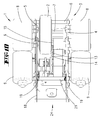
- an additional role performing unit 1 with a wheel 2, which assembly 1 can be mounted on a chassis as a whole.
- the wheel 2 is received in a frame 3, which consists in the embodiment of two frame parts 4, 5, which are interconnected to form a uniformly movable frame 3, for example via a transverse connection 6.
- Such a structural unit 1 can be attached, for example, to a hospital bed. But it can also be attached to transport devices such as a container or a shopping cart or the like. It serves to drive drive of such an object.
- Chassis side so for example on the hospital bed, usually a battery and various controls are still provided which are suitably electrically connected to the unit 1 then.
- the frame parts 4, 5 preferably extend parallel to one another.
- the wheel 2 is, with respect to the frame parts 4, 5, as in particular approximately out FIG. 3 results, off-center, namely arranged closer to the frame part 5.
- a favorable nesting is achieved with the further described units.
- the running direction of the wheel 2 is parallel to the frame parts 4, 5.
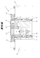
- the shaft 7, see also FIG. 4 of the wheel 2 is received in stock in the frame parts 4, 5.
- the shaft 7 protrudes on both sides beyond the frame parts 4, 5 and is there in each case connected to a transmission 8 and an electric motor 9.
- the gear 8 and the electric motor 9 are each secured to the frame part 4 or 5 from the outside.
- the transmission 8 is preferably designed so that it is not self-locking and has the lowest possible internal friction. Hereby, for example, a freewheeling effect can be achieved.
- a mounting plate 11 is provided in addition to the frame parts 4, 5, a mounting plate 11 is provided.
- the frame 3 is pivotally connected to an axis 12 with the mounting plate 11 connected in the installed state fixed to the chassis of the object in question.
- the axis 12 is screw-connected in the embodiment with the frame parts designed as a frame walls 4, 5.
- the frame parts 4, 5 are preferably not only connected by the axis 12, but also by the said shaft 7 of the wheel 2 and cross connections 6.
- a compression spring 13 is provided, which is connected at one end to the chassis or the mounting plate 11 in the execution subject, see FIG. 4 , and at the other end with the frame 3.
- the compression spring 13 is arranged on a particular also buckling of the coil spring preventing telescopic tube 14, wherein the telescopic tube 14, in the embodiment via strap ends 15, on the one hand cooperates with a pivot axis 16 of the mounting plate 11 and on the other hand with a cross connection 6.
- the compression spring 13 acts such that it presses the frame 3 in this raised position.
- the lowered position compare for example FIG. 7 , it generates the main force which presses the wheel 2 on the ground.
- a preferably formed as a leg spring Absenkfeder 25 is further provided. The lowering spring 25 is particularly important in that it overcomes the in accordance with the position FIG. 4 allows in the raised position force component of the compression spring 13 in the course of a lowering operation.
- the compression spring 13 exerts a force approximately 3 to 5 times, more preferably approximately 4 times, higher than the lowering spring 25.
- the compression spring 13 moves with the frame 3 around the fixed chassis pivot point, given here by the pivot axis 16, when raising or lowering the wheel. 2
- the articulation of the compression spring 13 on the frame 3, here by means of the transverse connection 6, can be seen in the raised position shown in Figure 4 above the articulation 16 on the chassis.
- the vertical distance is comparatively low.
- the distance dimension is smaller than corresponds to a diameter of the compression spring 13 designed here as a helical spring.
- the compression spring 13 is located between the frame parts 4 and 5.
- the compression spring 13 is in the raised state according to FIG. 4 also recorded in a horizontal projection within the frame parts 4 and 5.
- she can protrude from the frame over part of her length.
- an actuating lever 18 is provided, with which the wheel 2 together with the frame 3 from a lowered position according to FIG. 7 respectively FIG. 8 in any case partially raised position according to FIG. 12 is displaceable solely by, for example, physical strength.
- the lever 18 is on the one hand via a further cross-connection 29, which, based approximately on the illustration in FIG. 4 , a lower edge of the frame parts 4, 5 is associated, rotatably arranged.
- the actuating lever 18 by means of a spring 19 in a position according to FIG. 5 biased.
- the mounting plate 11 extends in cross section, as can be seen, angular.
- the recesses 22, 23 are formed on a vertical portion of this angle-shaped mounting plate. Therefore, they are chassisfest.
Landscapes
- Engineering & Computer Science (AREA)
- Health & Medical Sciences (AREA)
- Chemical & Material Sciences (AREA)
- Combustion & Propulsion (AREA)
- Transportation (AREA)
- Mechanical Engineering (AREA)
- Animal Behavior & Ethology (AREA)
- Life Sciences & Earth Sciences (AREA)
- General Health & Medical Sciences (AREA)
- Public Health (AREA)
- Veterinary Medicine (AREA)
- Nursing (AREA)
- Handcart (AREA)
- Legs For Furniture In General (AREA)
- Rolls And Other Rotary Bodies (AREA)
- Invalid Beds And Related Equipment (AREA)
- Support Of The Bearing (AREA)
Claims (10)
- Roulette supplémentaire, munie d'un cadre (3) rigide et comportant une roue (2) actionnable, logée dans le cadre (3) et munie d'un axe (7), ladite roue (2), conjointement avec le cadre (3), pouvant être relevée et abaissée par pivotement par rapport à un châssis sur lequel la roulette supplémentaire est destinée à être montée, et il est prévu un ressort de pression (13) articulé sur le châssis de manière à tourner au niveau d'une extrémité, afin de solliciter la roue (2) pour un contact au sol dans la position abaissée, caractérisée en ce qu'il est prévu une liaison transversale (6) reliant deux parties (4, 5) du cadre dans la direction d'un axe (7) de la roue (2), en ce que le ressort de pression (13), au niveau de l'autre extrémité, est articulé contre la liaison transversale (6) et en ce que le ressort de pression (13) pivote avec le cadre (3) autour d'un point de rotation (12) solidaire du châssis en cas de levage ou d'abaissement de la roue (2).
- Roulette supplémentaire selon la revendication 1, caractérisée en ce que l'articulation du ressort de pression (13) contre le cadre (3) se situe, dans la position relevée de la roue (2), au-dessus de l'articulation de la roue (2) contre le châssis.
- Roulette supplémentaire selon l'une quelconque des revendications précédentes, caractérisée en ce que le ressort de pression (13) est traversé par une tige de guidage (14).
- Roulette supplémentaire selon la revendication 3, caractérisée en ce que la tige de guidage (14) est télescopique.
- Roulette supplémentaire selon l'une quelconque des revendications précédentes, caractérisée en ce que, sur une projection verticale, le ressort de pression (13) est disposé à l'intérieur du cadre (3).
- Roulette supplémentaire selon l'une quelconque des revendications précédentes, caractérisée en ce qu'un levier d'actionnement (18), en saillie vers l'extérieur, est articulé contre le cadre (3) afin de faire pivoter la roue (2) dans la position relevée sans l'aide d'un moteur.
- Roulette supplémentaire selon la revendication 6, caractérisée en ce que le levier (18) est apte à pivoter tant par rapport au cadre (3) que par rapport à une plaque de montage (11) ou le châssis.
- Roulette supplémentaire selon la revendication 6 ou 7, caractérisée en ce que le levier (18) est précontraint dans sa position permettant la position abaissée de la roue (2).
- Roulette supplémentaire selon l'une quelconque des revendications précédentes, caractérisée en ce qu'il est prévu deux moteurs électriques (9) pour actionner la roue (2) et en ce que lesdits moteurs électriques (9) sont disposés en face de la roue (2).
- Roulette supplémentaire selon l'une quelconque des revendications précédentes, caractérisée en ce que la roue (2) peut être actionnée par au moins un moteur électrique (9), ledit au moins un moteur électrique (9) pouvant être connecté sous forme de générateur et/ou pouvant être actionné dans deux directions.
Priority Applications (2)
| Application Number | Priority Date | Filing Date | Title |
|---|---|---|---|
| SI201230178T SI2675416T1 (sl) | 2011-02-18 | 2012-01-24 | Dodatni valj |
| PL12700981T PL2675416T3 (pl) | 2011-02-18 | 2012-01-24 | Rolka pomocnicza |
Applications Claiming Priority (2)
| Application Number | Priority Date | Filing Date | Title |
|---|---|---|---|
| DE102011000817A DE102011000817A1 (de) | 2011-02-18 | 2011-02-18 | Zusatzrolle |
| PCT/EP2012/051014 WO2012110283A1 (fr) | 2011-02-18 | 2012-01-24 | Roulette supplémentaire |
Publications (2)
| Publication Number | Publication Date |
|---|---|
| EP2675416A1 EP2675416A1 (fr) | 2013-12-25 |
| EP2675416B1 true EP2675416B1 (fr) | 2015-01-28 |
Family
ID=45529096
Family Applications (1)
| Application Number | Title | Priority Date | Filing Date |
|---|---|---|---|
| EP12700981.9A Active EP2675416B1 (fr) | 2011-02-18 | 2012-01-24 | Roulette auxiliaire |
Country Status (15)
| Country | Link |
|---|---|
| US (1) | US8978795B2 (fr) |
| EP (1) | EP2675416B1 (fr) |
| JP (1) | JP5801419B2 (fr) |
| KR (1) | KR101832973B1 (fr) |
| CN (1) | CN103370038B (fr) |
| BR (1) | BR112013020932A2 (fr) |
| CA (1) | CA2825244C (fr) |
| DE (1) | DE102011000817A1 (fr) |
| DK (1) | DK2675416T3 (fr) |
| ES (1) | ES2531667T3 (fr) |
| MY (1) | MY164028A (fr) |
| PL (1) | PL2675416T3 (fr) |
| PT (1) | PT2675416E (fr) |
| SI (1) | SI2675416T1 (fr) |
| WO (1) | WO2012110283A1 (fr) |
Cited By (1)
| Publication number | Priority date | Publication date | Assignee | Title |
|---|---|---|---|---|
| DE102017121162A1 (de) | 2016-09-15 | 2018-03-15 | Tente Gmbh & Co. Kg | Über ein Schaltgestänge zu betätigende Rollen sowie Verfahrwagen mit zwei Rollenpaaren |
Families Citing this family (19)
| Publication number | Priority date | Publication date | Assignee | Title |
|---|---|---|---|---|
| US20120198620A1 (en) * | 2011-02-08 | 2012-08-09 | Hornbach David W | Motorized center wheel deployment mechanism for a patient support |
| DE102014108002A1 (de) | 2013-06-19 | 2014-12-24 | Tente Gmbh & Co. Kg | Rolle mit angetriebenem Rad, Lastenwagen mit ein angetriebenes Rad aufweisender Rolle und Bediengerät |
| DE202013105191U1 (de) | 2013-11-18 | 2015-02-19 | Tente Gmbh & Co. Kg | Steuerung von an einem Verfahrteil angebrachten Rollen |
| DE102014100056A1 (de) | 2013-11-18 | 2015-05-21 | Tente Gmbh & Co. Kg | Steuerung von an einem Verfahrteil angebrachten Rollen |
| DE102014107973A1 (de) | 2014-06-05 | 2015-12-17 | Tente Gmbh & Co. Kg | Mit zwei motorisch angetriebenen Laufrädern und einer Steuerung versehener Lastwagen |
| US10377403B2 (en) * | 2015-11-06 | 2019-08-13 | Caster Concepts, Inc. | Powered utility cart and compliant drive wheel therefor |
| PL3624748T3 (pl) * | 2017-05-15 | 2021-11-02 | Huntleigh Technology Limited | Odwracalna sprężyna do podnoszenia i opuszczania piątego koła łóżka medycznego |
| US11071662B2 (en) | 2017-12-28 | 2021-07-27 | Stryker Corporation | Patient transport apparatus with controlled auxiliary wheel speed |
| US10799403B2 (en) | 2017-12-28 | 2020-10-13 | Stryker Corporation | Patient transport apparatus with controlled auxiliary wheel deployment |
| US11304860B2 (en) | 2018-11-21 | 2022-04-19 | Stryker Corporation | Patient transport apparatus with auxiliary wheel system |
| US11484447B2 (en) | 2018-11-21 | 2022-11-01 | Stryker Corporation | Patient transport apparatus with controlled auxiliary wheel deployment |
| KR102263188B1 (ko) * | 2019-10-08 | 2021-06-09 | 명세씨엠케이 주식회사 | 전동 보조형 이동식 대상체 탑재장치 |
| US11863007B1 (en) * | 2019-12-11 | 2024-01-02 | Amazon Technologies, Inc. | Wheel-based charger for wireless smart controllers and carts |
| US11806296B2 (en) | 2019-12-30 | 2023-11-07 | Stryker Corporation | Patient transport apparatus with controlled auxiliary wheel speed |
| PL242740B1 (pl) * | 2020-02-27 | 2023-04-17 | Wamech Producent Wozkow Przemyslowych Piotr I Albina Wasik Spolka Jawna | Zestaw transportowy |
| CN112896367B (zh) * | 2021-03-31 | 2024-04-09 | 华南理工大学 | 一种可在舵轮和万向轮间切换的机器人底盘 |
| EP4329694A1 (fr) | 2021-04-30 | 2024-03-06 | Tente GmbH & Co. KG | Unité de commande et procédé de commande de rouleaux montés sur une partie mobile |
| DE102022106363A1 (de) | 2021-04-30 | 2022-11-03 | Tente Gmbh & Co. Kg | Steuerung sowie Verfahren zur Steuerung von an einem Verfahrteil angebrachten Rollen |
| NL2029263B1 (nl) * | 2021-09-28 | 2023-04-04 | Kaars Koffie B V | Mobiel koffiezetapparaat |
Family Cites Families (14)
| Publication number | Priority date | Publication date | Assignee | Title |
|---|---|---|---|---|
| US1172456A (en) * | 1915-03-19 | 1916-02-22 | Alfred Henry Hoadley | Motor driving-wheel. |
| US3263983A (en) | 1963-12-30 | 1966-08-02 | Ford Motor Co | Shock absorber and auxiliary spring unit |
| US3380546A (en) * | 1966-02-14 | 1968-04-30 | Rodney R. Rabjohn | Traction drive for small vehicles |
| JPS6116122U (ja) * | 1984-07-04 | 1986-01-30 | 健三 茶畑 | 車椅子 |
| US5806111A (en) * | 1996-04-12 | 1998-09-15 | Hill-Rom, Inc. | Stretcher controls |
| US6330926B1 (en) * | 1999-09-15 | 2001-12-18 | Hill-Rom Services, Inc. | Stretcher having a motorized wheel |
| US7014000B2 (en) * | 2000-05-11 | 2006-03-21 | Hill-Rom Services, Inc. | Braking apparatus for a patient support |
| US6752224B2 (en) | 2002-02-28 | 2004-06-22 | Stryker Corporation | Wheeled carriage having a powered auxiliary wheel, auxiliary wheel overtravel, and an auxiliary wheel drive and control system |
| JP4471744B2 (ja) * | 2004-06-16 | 2010-06-02 | パラマウントベッド株式会社 | ベッド電動搬送装置及びその駆動制御方法 |
| DE102006007377A1 (de) * | 2006-02-17 | 2007-08-30 | Tente Gmbh & Co. Kg | Krankenhausbett mit einer weiteren in Bodenkontakt bringbaren wahlweise antreibbaren Zusatzrolle |
| US7419019B1 (en) | 2006-03-23 | 2008-09-02 | Safe-T-Care Manufacturing, Co., Inc. | Power assist apparatus for use with a hospital bed |
| US7882582B2 (en) | 2006-10-13 | 2011-02-08 | Hill-Rom Services, Inc. | User interface and control system for powered transport device of a patient support apparatus |
| JP2009292373A (ja) * | 2008-06-06 | 2009-12-17 | New Delta Ind Co | 作業台車 |
| US8567537B2 (en) * | 2009-09-18 | 2013-10-29 | Honda Motor Co., Ltd | Inverted pendulum type vehicle |
-
2011
- 2011-02-18 DE DE102011000817A patent/DE102011000817A1/de not_active Withdrawn
-
2012
- 2012-01-24 ES ES12700981.9T patent/ES2531667T3/es active Active
- 2012-01-24 PL PL12700981T patent/PL2675416T3/pl unknown
- 2012-01-24 BR BR112013020932A patent/BR112013020932A2/pt not_active IP Right Cessation
- 2012-01-24 JP JP2013553858A patent/JP5801419B2/ja active Active
- 2012-01-24 SI SI201230178T patent/SI2675416T1/sl unknown
- 2012-01-24 PT PT12700981T patent/PT2675416E/pt unknown
- 2012-01-24 EP EP12700981.9A patent/EP2675416B1/fr active Active
- 2012-01-24 DK DK12700981.9T patent/DK2675416T3/en active
- 2012-01-24 CA CA2825244A patent/CA2825244C/fr active Active
- 2012-01-24 WO PCT/EP2012/051014 patent/WO2012110283A1/fr active Application Filing
- 2012-01-24 KR KR1020137024660A patent/KR101832973B1/ko active IP Right Grant
- 2012-01-24 MY MYPI2013002818A patent/MY164028A/en unknown
- 2012-01-24 CN CN201280009359.4A patent/CN103370038B/zh active Active
- 2012-01-24 US US13/981,403 patent/US8978795B2/en active Active
Cited By (2)
| Publication number | Priority date | Publication date | Assignee | Title |
|---|---|---|---|---|
| DE102017121162A1 (de) | 2016-09-15 | 2018-03-15 | Tente Gmbh & Co. Kg | Über ein Schaltgestänge zu betätigende Rollen sowie Verfahrwagen mit zwei Rollenpaaren |
| WO2018050691A1 (fr) | 2016-09-15 | 2018-03-22 | Tente Gmbh & Co. Kg | Roues à pivot à actionner par l'intermédiaire d'une tringlerie de commande et chariot mobile doté de deux paires de roues à pivot |
Also Published As
| Publication number | Publication date |
|---|---|
| CA2825244C (fr) | 2019-06-11 |
| DE102011000817A1 (de) | 2012-08-23 |
| JP2014511299A (ja) | 2014-05-15 |
| SI2675416T1 (sl) | 2015-05-29 |
| MY164028A (en) | 2017-11-15 |
| KR20140023285A (ko) | 2014-02-26 |
| PL2675416T3 (pl) | 2015-08-31 |
| CN103370038A (zh) | 2013-10-23 |
| ES2531667T3 (es) | 2015-03-18 |
| JP5801419B2 (ja) | 2015-10-28 |
| US20130299252A1 (en) | 2013-11-14 |
| DK2675416T3 (en) | 2015-05-04 |
| CN103370038B (zh) | 2017-02-08 |
| CA2825244A1 (fr) | 2012-08-23 |
| KR101832973B1 (ko) | 2018-02-28 |
| EP2675416A1 (fr) | 2013-12-25 |
| BR112013020932A2 (pt) | 2016-10-11 |
| PT2675416E (pt) | 2015-03-04 |
| US8978795B2 (en) | 2015-03-17 |
| WO2012110283A1 (fr) | 2012-08-23 |
Similar Documents
| Publication | Publication Date | Title |
|---|---|---|
| EP2675416B1 (fr) | Roulette auxiliaire | |
| EP1925540B1 (fr) | Entraînement d'assistance pour une remorque | |
| EP2452664B1 (fr) | Table d'opération | |
| EP0466065B1 (fr) | Véhicule de transport de charges | |
| DE102008021604B4 (de) | Einrichtung zum Betätigen von Bremseinrichtungen einer fahrbaren Vorrichtung, fahrbares Gestell und medizinisches Gerät | |
| EP2069206A1 (fr) | Dispositif d'emballage, mécanisme de blocage pour un dispositif d'emballage et procédé destiné à mettre en uvre ce dernier | |
| EP3318431B1 (fr) | Remorque de train de remorques | |
| DE4420460A1 (de) | Transportwagen | |
| EP1868934B1 (fr) | Dispositif de levage de roue et balance pourvue d'un tel dispositif | |
| EP1826164B1 (fr) | Presse pour palettes | |
| WO1998043856A2 (fr) | Appareil de levage pour vehicules a moteur et attelages de vehicules, en particulier cric | |
| EP0666209B1 (fr) | Chariot de transport, en particulier conteneur roulant comportant des pieds de support retractables | |
| WO2018050691A1 (fr) | Roues à pivot à actionner par l'intermédiaire d'une tringlerie de commande et chariot mobile doté de deux paires de roues à pivot | |
| EP1362823A1 (fr) | Elévateur pour véhicules, à bras porteurs | |
| EP3806802B1 (fr) | Système de transport | |
| EP0816279A1 (fr) | Cric de véhicule pour manoeuvrer | |
| EP0666208A1 (fr) | Chariot de transport, en particulier conteneur roulant comportant des pieds de support retractables | |
| EP2710927A1 (fr) | Pied, en particulier pied de meuble | |
| EP2251278B1 (fr) | Dispositif destiné à lever des éléments de charge | |
| EP4001203A1 (fr) | Plateforme de levage à soufflet à air | |
| EP2318301A1 (fr) | Plate-forme de levage | |
| EP3403988A1 (fr) | Dispositif support et pont élévateur pour véhicule comprenant un dispositif support | |
| AT6328U1 (de) | Transportfahrzeug | |
| DE202004007564U1 (de) | Möbel (Freilauf) | |
| AT15076U1 (de) | Rollbehälter |
Legal Events
| Date | Code | Title | Description |
|---|---|---|---|
| PUAI | Public reference made under article 153(3) epc to a published international application that has entered the european phase |
Free format text: ORIGINAL CODE: 0009012 |
|
| 17P | Request for examination filed |
Effective date: 20130916 |
|
| AK | Designated contracting states |
Kind code of ref document: A1 Designated state(s): AL AT BE BG CH CY CZ DE DK EE ES FI FR GB GR HR HU IE IS IT LI LT LU LV MC MK MT NL NO PL PT RO RS SE SI SK SM TR |
|
| DAX | Request for extension of the european patent (deleted) | ||
| RIC1 | Information provided on ipc code assigned before grant |
Ipc: A61G 7/08 20060101AFI20140617BHEP Ipc: A61G 5/04 20130101ALI20140617BHEP Ipc: B60K 1/02 20060101ALI20140617BHEP Ipc: B62B 5/00 20060101ALI20140617BHEP Ipc: B60K 1/00 20060101ALI20140617BHEP |
|
| GRAP | Despatch of communication of intention to grant a patent |
Free format text: ORIGINAL CODE: EPIDOSNIGR1 |
|
| INTG | Intention to grant announced |
Effective date: 20140829 |
|
| GRAS | Grant fee paid |
Free format text: ORIGINAL CODE: EPIDOSNIGR3 |
|
| GRAA | (expected) grant |
Free format text: ORIGINAL CODE: 0009210 |
|
| AK | Designated contracting states |
Kind code of ref document: B1 Designated state(s): AL AT BE BG CH CY CZ DE DK EE ES FI FR GB GR HR HU IE IS IT LI LT LU LV MC MK MT NL NO PL PT RO RS SE SI SK SM TR |
|
| REG | Reference to a national code |
Ref country code: GB Ref legal event code: FG4D Free format text: NOT ENGLISH |
|
| REG | Reference to a national code |
Ref country code: CH Ref legal event code: EP |
|
| REG | Reference to a national code |
Ref country code: CH Ref legal event code: NV Representative=s name: R. A. EGLI AND CO. PATENTANWAELTE, CH |
|
| REG | Reference to a national code |
Ref country code: IE Ref legal event code: FG4D Free format text: LANGUAGE OF EP DOCUMENT: GERMAN |
|
| REG | Reference to a national code |
Ref country code: PT Ref legal event code: SC4A Free format text: AVAILABILITY OF NATIONAL TRANSLATION Effective date: 20150226 |
|
| REG | Reference to a national code |
Ref country code: DE Ref legal event code: R096 Ref document number: 502012002221 Country of ref document: DE Effective date: 20150312 |
|
| REG | Reference to a national code |
Ref country code: AT Ref legal event code: REF Ref document number: 707919 Country of ref document: AT Kind code of ref document: T Effective date: 20150315 |
|
| REG | Reference to a national code |
Ref country code: ES Ref legal event code: FG2A Ref document number: 2531667 Country of ref document: ES Kind code of ref document: T3 Effective date: 20150318 |
|
| REG | Reference to a national code |
Ref country code: SE Ref legal event code: TRGR |
|
| REG | Reference to a national code |
Ref country code: DK Ref legal event code: T3 Effective date: 20150430 |
|
| REG | Reference to a national code |
Ref country code: GR Ref legal event code: EP Ref document number: 20150400681 Country of ref document: GR Effective date: 20150421 |
|
| REG | Reference to a national code |
Ref country code: LT Ref legal event code: MG4D |
|
| REG | Reference to a national code |
Ref country code: NO Ref legal event code: T2 Effective date: 20150128 |
|
| PG25 | Lapsed in a contracting state [announced via postgrant information from national office to epo] |
Ref country code: HR Free format text: LAPSE BECAUSE OF FAILURE TO SUBMIT A TRANSLATION OF THE DESCRIPTION OR TO PAY THE FEE WITHIN THE PRESCRIBED TIME-LIMIT Effective date: 20150128 Ref country code: LT Free format text: LAPSE BECAUSE OF FAILURE TO SUBMIT A TRANSLATION OF THE DESCRIPTION OR TO PAY THE FEE WITHIN THE PRESCRIBED TIME-LIMIT Effective date: 20150128 Ref country code: BG Free format text: LAPSE BECAUSE OF FAILURE TO SUBMIT A TRANSLATION OF THE DESCRIPTION OR TO PAY THE FEE WITHIN THE PRESCRIBED TIME-LIMIT Effective date: 20150428 |
|
| PG25 | Lapsed in a contracting state [announced via postgrant information from national office to epo] |
Ref country code: RS Free format text: LAPSE BECAUSE OF FAILURE TO SUBMIT A TRANSLATION OF THE DESCRIPTION OR TO PAY THE FEE WITHIN THE PRESCRIBED TIME-LIMIT Effective date: 20150128 Ref country code: LV Free format text: LAPSE BECAUSE OF FAILURE TO SUBMIT A TRANSLATION OF THE DESCRIPTION OR TO PAY THE FEE WITHIN THE PRESCRIBED TIME-LIMIT Effective date: 20150128 Ref country code: IS Free format text: LAPSE BECAUSE OF FAILURE TO SUBMIT A TRANSLATION OF THE DESCRIPTION OR TO PAY THE FEE WITHIN THE PRESCRIBED TIME-LIMIT Effective date: 20150528 |
|
| REG | Reference to a national code |
Ref country code: PL Ref legal event code: T3 |
|
| REG | Reference to a national code |
Ref country code: HU Ref legal event code: AG4A Ref document number: E024126 Country of ref document: HU |
|
| REG | Reference to a national code |
Ref country code: DE Ref legal event code: R097 Ref document number: 502012002221 Country of ref document: DE |
|
| PG25 | Lapsed in a contracting state [announced via postgrant information from national office to epo] |
Ref country code: EE Free format text: LAPSE BECAUSE OF FAILURE TO SUBMIT A TRANSLATION OF THE DESCRIPTION OR TO PAY THE FEE WITHIN THE PRESCRIBED TIME-LIMIT Effective date: 20150128 Ref country code: RO Free format text: LAPSE BECAUSE OF FAILURE TO SUBMIT A TRANSLATION OF THE DESCRIPTION OR TO PAY THE FEE WITHIN THE PRESCRIBED TIME-LIMIT Effective date: 20150128 Ref country code: SK Free format text: LAPSE BECAUSE OF FAILURE TO SUBMIT A TRANSLATION OF THE DESCRIPTION OR TO PAY THE FEE WITHIN THE PRESCRIBED TIME-LIMIT Effective date: 20150128 |
|
| PLBE | No opposition filed within time limit |
Free format text: ORIGINAL CODE: 0009261 |
|
| STAA | Information on the status of an ep patent application or granted ep patent |
Free format text: STATUS: NO OPPOSITION FILED WITHIN TIME LIMIT |
|
| 26N | No opposition filed |
Effective date: 20151029 |
|
| REG | Reference to a national code |
Ref country code: FR Ref legal event code: PLFP Year of fee payment: 5 |
|
| PG25 | Lapsed in a contracting state [announced via postgrant information from national office to epo] |
Ref country code: BE Free format text: LAPSE BECAUSE OF NON-PAYMENT OF DUE FEES Effective date: 20160131 |
|
| REG | Reference to a national code |
Ref country code: NO Ref legal event code: MMEP |
|
| PG25 | Lapsed in a contracting state [announced via postgrant information from national office to epo] |
Ref country code: LU Free format text: LAPSE BECAUSE OF FAILURE TO SUBMIT A TRANSLATION OF THE DESCRIPTION OR TO PAY THE FEE WITHIN THE PRESCRIBED TIME-LIMIT Effective date: 20160124 |
|
| REG | Reference to a national code |
Ref country code: CH Ref legal event code: PL |
|
| PG25 | Lapsed in a contracting state [announced via postgrant information from national office to epo] |
Ref country code: MC Free format text: LAPSE BECAUSE OF FAILURE TO SUBMIT A TRANSLATION OF THE DESCRIPTION OR TO PAY THE FEE WITHIN THE PRESCRIBED TIME-LIMIT Effective date: 20150128 |
|
| REG | Reference to a national code |
Ref country code: GR Ref legal event code: ML Ref document number: 20150400681 Country of ref document: GR Effective date: 20160803 |
|
| REG | Reference to a national code |
Ref country code: SI Ref legal event code: KO00 Effective date: 20160906 |
|
| PG25 | Lapsed in a contracting state [announced via postgrant information from national office to epo] |
Ref country code: HU Free format text: LAPSE BECAUSE OF NON-PAYMENT OF DUE FEES Effective date: 20160125 Ref country code: NO Free format text: LAPSE BECAUSE OF NON-PAYMENT OF DUE FEES Effective date: 20160131 Ref country code: CH Free format text: LAPSE BECAUSE OF NON-PAYMENT OF DUE FEES Effective date: 20160131 Ref country code: LI Free format text: LAPSE BECAUSE OF NON-PAYMENT OF DUE FEES Effective date: 20160131 |
|
| REG | Reference to a national code |
Ref country code: IE Ref legal event code: MM4A |
|
| PG25 | Lapsed in a contracting state [announced via postgrant information from national office to epo] |
Ref country code: SI Free format text: LAPSE BECAUSE OF NON-PAYMENT OF DUE FEES Effective date: 20160125 Ref country code: GR Free format text: LAPSE BECAUSE OF NON-PAYMENT OF DUE FEES Effective date: 20160803 Ref country code: CZ Free format text: LAPSE BECAUSE OF NON-PAYMENT OF DUE FEES Effective date: 20160124 |
|
| REG | Reference to a national code |
Ref country code: FR Ref legal event code: PLFP Year of fee payment: 6 |
|
| PG25 | Lapsed in a contracting state [announced via postgrant information from national office to epo] |
Ref country code: IE Free format text: LAPSE BECAUSE OF NON-PAYMENT OF DUE FEES Effective date: 20160124 |
|
| PG25 | Lapsed in a contracting state [announced via postgrant information from national office to epo] |
Ref country code: MT Free format text: LAPSE BECAUSE OF FAILURE TO SUBMIT A TRANSLATION OF THE DESCRIPTION OR TO PAY THE FEE WITHIN THE PRESCRIBED TIME-LIMIT Effective date: 20150128 |
|
| REG | Reference to a national code |
Ref country code: FR Ref legal event code: PLFP Year of fee payment: 7 |
|
| PG25 | Lapsed in a contracting state [announced via postgrant information from national office to epo] |
Ref country code: CY Free format text: LAPSE BECAUSE OF FAILURE TO SUBMIT A TRANSLATION OF THE DESCRIPTION OR TO PAY THE FEE WITHIN THE PRESCRIBED TIME-LIMIT Effective date: 20150128 Ref country code: SM Free format text: LAPSE BECAUSE OF FAILURE TO SUBMIT A TRANSLATION OF THE DESCRIPTION OR TO PAY THE FEE WITHIN THE PRESCRIBED TIME-LIMIT Effective date: 20150128 |
|
| PG25 | Lapsed in a contracting state [announced via postgrant information from national office to epo] |
Ref country code: MK Free format text: LAPSE BECAUSE OF FAILURE TO SUBMIT A TRANSLATION OF THE DESCRIPTION OR TO PAY THE FEE WITHIN THE PRESCRIBED TIME-LIMIT Effective date: 20150128 |
|
| PG25 | Lapsed in a contracting state [announced via postgrant information from national office to epo] |
Ref country code: AL Free format text: LAPSE BECAUSE OF FAILURE TO SUBMIT A TRANSLATION OF THE DESCRIPTION OR TO PAY THE FEE WITHIN THE PRESCRIBED TIME-LIMIT Effective date: 20150128 |
|
| PGFP | Annual fee paid to national office [announced via postgrant information from national office to epo] |
Ref country code: NO Payment date: 20190220 Year of fee payment: 9 |
|
| PGFP | Annual fee paid to national office [announced via postgrant information from national office to epo] |
Ref country code: AT Payment date: 20200117 Year of fee payment: 9 |
|
| REG | Reference to a national code |
Ref country code: FI Ref legal event code: MAE |
|
| PG25 | Lapsed in a contracting state [announced via postgrant information from national office to epo] |
Ref country code: FI Free format text: LAPSE BECAUSE OF NON-PAYMENT OF DUE FEES Effective date: 20200124 |
|
| REG | Reference to a national code |
Ref country code: AT Ref legal event code: MM01 Ref document number: 707919 Country of ref document: AT Kind code of ref document: T Effective date: 20210124 |
|
| PG25 | Lapsed in a contracting state [announced via postgrant information from national office to epo] |
Ref country code: AT Free format text: LAPSE BECAUSE OF NON-PAYMENT OF DUE FEES Effective date: 20210124 |
|
| PGFP | Annual fee paid to national office [announced via postgrant information from national office to epo] |
Ref country code: PT Payment date: 20211026 Year of fee payment: 11 |
|
| PGFP | Annual fee paid to national office [announced via postgrant information from national office to epo] |
Ref country code: PL Payment date: 20221215 Year of fee payment: 12 |
|
| PGFP | Annual fee paid to national office [announced via postgrant information from national office to epo] |
Ref country code: FR Payment date: 20230113 Year of fee payment: 12 Ref country code: DK Payment date: 20230117 Year of fee payment: 12 |
|
| PGFP | Annual fee paid to national office [announced via postgrant information from national office to epo] |
Ref country code: TR Payment date: 20230112 Year of fee payment: 12 Ref country code: SE Payment date: 20230113 Year of fee payment: 12 Ref country code: IT Payment date: 20230126 Year of fee payment: 12 Ref country code: GB Payment date: 20230127 Year of fee payment: 12 |
|
| P01 | Opt-out of the competence of the unified patent court (upc) registered |
Effective date: 20230523 |
|
| PG25 | Lapsed in a contracting state [announced via postgrant information from national office to epo] |
Ref country code: PT Free format text: LAPSE BECAUSE OF NON-PAYMENT OF DUE FEES Effective date: 20230724 |
|
| PGFP | Annual fee paid to national office [announced via postgrant information from national office to epo] |
Ref country code: NL Payment date: 20240119 Year of fee payment: 13 |
|
| PGFP | Annual fee paid to national office [announced via postgrant information from national office to epo] |
Ref country code: ES Payment date: 20240214 Year of fee payment: 13 |
|
| PGFP | Annual fee paid to national office [announced via postgrant information from national office to epo] |
Ref country code: DE Payment date: 20230202 Year of fee payment: 13 |