EP2675009A1 - Système de génération d'électricité et procédé pour faire fonctionner ledit système - Google Patents
Système de génération d'électricité et procédé pour faire fonctionner ledit système Download PDFInfo
- Publication number
- EP2675009A1 EP2675009A1 EP12763129.9A EP12763129A EP2675009A1 EP 2675009 A1 EP2675009 A1 EP 2675009A1 EP 12763129 A EP12763129 A EP 12763129A EP 2675009 A1 EP2675009 A1 EP 2675009A1
- Authority
- EP
- European Patent Office
- Prior art keywords
- combustor
- controller
- combustion
- air
- fuel cell
- Prior art date
- Legal status (The legal status is an assumption and is not a legal conclusion. Google has not performed a legal analysis and makes no representation as to the accuracy of the status listed.)
- Granted
Links
- 238000010248 power generation Methods 0.000 title claims abstract description 170
- 238000000034 method Methods 0.000 title claims description 12
- 238000002485 combustion reaction Methods 0.000 claims abstract description 356
- 239000000446 fuel Substances 0.000 claims abstract description 314
- UFHFLCQGNIYNRP-UHFFFAOYSA-N Hydrogen Chemical compound [H][H] UFHFLCQGNIYNRP-UHFFFAOYSA-N 0.000 claims abstract description 38
- 239000001257 hydrogen Substances 0.000 claims abstract description 38
- 229910052739 hydrogen Inorganic materials 0.000 claims abstract description 38
- 239000007789 gas Substances 0.000 claims description 339
- 239000002737 fuel gas Substances 0.000 claims description 59
- 230000001590 oxidative effect Effects 0.000 claims description 50
- 230000008859 change Effects 0.000 claims description 43
- 230000003247 decreasing effect Effects 0.000 claims description 33
- 230000007423 decrease Effects 0.000 claims description 21
- 238000007599 discharging Methods 0.000 claims description 5
- 239000000567 combustion gas Substances 0.000 claims description 2
- 238000009423 ventilation Methods 0.000 description 54
- XLYOFNOQVPJJNP-UHFFFAOYSA-N water Substances O XLYOFNOQVPJJNP-UHFFFAOYSA-N 0.000 description 32
- 230000003213 activating effect Effects 0.000 description 30
- 239000000463 material Substances 0.000 description 26
- UGFAIRIUMAVXCW-UHFFFAOYSA-N Carbon monoxide Chemical compound [O+]#[C-] UGFAIRIUMAVXCW-UHFFFAOYSA-N 0.000 description 25
- 230000004913 activation Effects 0.000 description 24
- 239000003546 flue gas Substances 0.000 description 18
- 239000003054 catalyst Substances 0.000 description 16
- 238000001514 detection method Methods 0.000 description 14
- 239000000203 mixture Substances 0.000 description 10
- VNWKTOKETHGBQD-UHFFFAOYSA-N methane Chemical compound C VNWKTOKETHGBQD-UHFFFAOYSA-N 0.000 description 8
- 229910002091 carbon monoxide Inorganic materials 0.000 description 7
- 238000002407 reforming Methods 0.000 description 7
- PXHVJJICTQNCMI-UHFFFAOYSA-N Nickel Chemical compound [Ni] PXHVJJICTQNCMI-UHFFFAOYSA-N 0.000 description 5
- 238000011144 upstream manufacturing Methods 0.000 description 5
- KJTLSVCANCCWHF-UHFFFAOYSA-N Ruthenium Chemical compound [Ru] KJTLSVCANCCWHF-UHFFFAOYSA-N 0.000 description 4
- 238000010586 diagram Methods 0.000 description 4
- 230000005611 electricity Effects 0.000 description 4
- 229910052707 ruthenium Inorganic materials 0.000 description 4
- 239000003345 natural gas Substances 0.000 description 3
- 239000004215 Carbon black (E152) Substances 0.000 description 2
- ATUOYWHBWRKTHZ-UHFFFAOYSA-N Propane Chemical compound CCC ATUOYWHBWRKTHZ-UHFFFAOYSA-N 0.000 description 2
- QVGXLLKOCUKJST-UHFFFAOYSA-N atomic oxygen Chemical compound [O] QVGXLLKOCUKJST-UHFFFAOYSA-N 0.000 description 2
- 229930195733 hydrocarbon Natural products 0.000 description 2
- 150000002430 hydrocarbons Chemical class 0.000 description 2
- 229910052759 nickel Inorganic materials 0.000 description 2
- 239000001301 oxygen Substances 0.000 description 2
- 229910052760 oxygen Inorganic materials 0.000 description 2
- 230000000149 penetrating effect Effects 0.000 description 2
- PNEYBMLMFCGWSK-UHFFFAOYSA-N aluminium oxide Inorganic materials [O-2].[O-2].[O-2].[Al+3].[Al+3] PNEYBMLMFCGWSK-UHFFFAOYSA-N 0.000 description 1
- 238000002453 autothermal reforming Methods 0.000 description 1
- 238000006243 chemical reaction Methods 0.000 description 1
- TVZPLCNGKSPOJA-UHFFFAOYSA-N copper zinc Chemical compound [Cu].[Zn] TVZPLCNGKSPOJA-UHFFFAOYSA-N 0.000 description 1
- 230000000694 effects Effects 0.000 description 1
- 239000011810 insulating material Substances 0.000 description 1
- 238000012986 modification Methods 0.000 description 1
- 230000004048 modification Effects 0.000 description 1
- 230000003647 oxidation Effects 0.000 description 1
- 238000007254 oxidation reaction Methods 0.000 description 1
- 239000005518 polymer electrolyte Substances 0.000 description 1
- 230000008569 process Effects 0.000 description 1
- 239000001294 propane Substances 0.000 description 1
- 238000006057 reforming reaction Methods 0.000 description 1
- 238000000629 steam reforming Methods 0.000 description 1
Images


Classifications
-
- H—ELECTRICITY
- H01—ELECTRIC ELEMENTS
- H01M—PROCESSES OR MEANS, e.g. BATTERIES, FOR THE DIRECT CONVERSION OF CHEMICAL ENERGY INTO ELECTRICAL ENERGY
- H01M8/00—Fuel cells; Manufacture thereof
- H01M8/04—Auxiliary arrangements, e.g. for control of pressure or for circulation of fluids
- H01M8/04007—Auxiliary arrangements, e.g. for control of pressure or for circulation of fluids related to heat exchange
- H01M8/04014—Heat exchange using gaseous fluids; Heat exchange by combustion of reactants
- H01M8/04022—Heating by combustion
-
- F—MECHANICAL ENGINEERING; LIGHTING; HEATING; WEAPONS; BLASTING
- F23—COMBUSTION APPARATUS; COMBUSTION PROCESSES
- F23N—REGULATING OR CONTROLLING COMBUSTION
- F23N1/00—Regulating fuel supply
- F23N1/02—Regulating fuel supply conjointly with air supply
- F23N1/022—Regulating fuel supply conjointly with air supply using electronic means
-
- F—MECHANICAL ENGINEERING; LIGHTING; HEATING; WEAPONS; BLASTING
- F23—COMBUSTION APPARATUS; COMBUSTION PROCESSES
- F23N—REGULATING OR CONTROLLING COMBUSTION
- F23N5/00—Systems for controlling combustion
- F23N5/003—Systems for controlling combustion using detectors sensitive to combustion gas properties
-
- H—ELECTRICITY
- H01—ELECTRIC ELEMENTS
- H01M—PROCESSES OR MEANS, e.g. BATTERIES, FOR THE DIRECT CONVERSION OF CHEMICAL ENERGY INTO ELECTRICAL ENERGY
- H01M8/00—Fuel cells; Manufacture thereof
- H01M8/04—Auxiliary arrangements, e.g. for control of pressure or for circulation of fluids
- H01M8/04223—Auxiliary arrangements, e.g. for control of pressure or for circulation of fluids during start-up or shut-down; Depolarisation or activation, e.g. purging; Means for short-circuiting defective fuel cells
- H01M8/04225—Auxiliary arrangements, e.g. for control of pressure or for circulation of fluids during start-up or shut-down; Depolarisation or activation, e.g. purging; Means for short-circuiting defective fuel cells during start-up
-
- H—ELECTRICITY
- H01—ELECTRIC ELEMENTS
- H01M—PROCESSES OR MEANS, e.g. BATTERIES, FOR THE DIRECT CONVERSION OF CHEMICAL ENERGY INTO ELECTRICAL ENERGY
- H01M8/00—Fuel cells; Manufacture thereof
- H01M8/04—Auxiliary arrangements, e.g. for control of pressure or for circulation of fluids
- H01M8/04223—Auxiliary arrangements, e.g. for control of pressure or for circulation of fluids during start-up or shut-down; Depolarisation or activation, e.g. purging; Means for short-circuiting defective fuel cells
- H01M8/04228—Auxiliary arrangements, e.g. for control of pressure or for circulation of fluids during start-up or shut-down; Depolarisation or activation, e.g. purging; Means for short-circuiting defective fuel cells during shut-down
-
- H—ELECTRICITY
- H01—ELECTRIC ELEMENTS
- H01M—PROCESSES OR MEANS, e.g. BATTERIES, FOR THE DIRECT CONVERSION OF CHEMICAL ENERGY INTO ELECTRICAL ENERGY
- H01M8/00—Fuel cells; Manufacture thereof
- H01M8/04—Auxiliary arrangements, e.g. for control of pressure or for circulation of fluids
- H01M8/04298—Processes for controlling fuel cells or fuel cell systems
- H01M8/043—Processes for controlling fuel cells or fuel cell systems applied during specific periods
- H01M8/04302—Processes for controlling fuel cells or fuel cell systems applied during specific periods applied during start-up
-
- H—ELECTRICITY
- H01—ELECTRIC ELEMENTS
- H01M—PROCESSES OR MEANS, e.g. BATTERIES, FOR THE DIRECT CONVERSION OF CHEMICAL ENERGY INTO ELECTRICAL ENERGY
- H01M8/00—Fuel cells; Manufacture thereof
- H01M8/04—Auxiliary arrangements, e.g. for control of pressure or for circulation of fluids
- H01M8/04298—Processes for controlling fuel cells or fuel cell systems
- H01M8/04694—Processes for controlling fuel cells or fuel cell systems characterised by variables to be controlled
- H01M8/04955—Shut-off or shut-down of fuel cells
-
- H—ELECTRICITY
- H01—ELECTRIC ELEMENTS
- H01M—PROCESSES OR MEANS, e.g. BATTERIES, FOR THE DIRECT CONVERSION OF CHEMICAL ENERGY INTO ELECTRICAL ENERGY
- H01M8/00—Fuel cells; Manufacture thereof
- H01M8/06—Combination of fuel cells with means for production of reactants or for treatment of residues
- H01M8/0606—Combination of fuel cells with means for production of reactants or for treatment of residues with means for production of gaseous reactants
- H01M8/0612—Combination of fuel cells with means for production of reactants or for treatment of residues with means for production of gaseous reactants from carbon-containing material
- H01M8/0618—Reforming processes, e.g. autothermal, partial oxidation or steam reforming
-
- H—ELECTRICITY
- H01—ELECTRIC ELEMENTS
- H01M—PROCESSES OR MEANS, e.g. BATTERIES, FOR THE DIRECT CONVERSION OF CHEMICAL ENERGY INTO ELECTRICAL ENERGY
- H01M8/00—Fuel cells; Manufacture thereof
- H01M8/24—Grouping of fuel cells, e.g. stacking of fuel cells
- H01M8/241—Grouping of fuel cells, e.g. stacking of fuel cells with solid or matrix-supported electrolytes
- H01M8/2425—High-temperature cells with solid electrolytes
-
- F—MECHANICAL ENGINEERING; LIGHTING; HEATING; WEAPONS; BLASTING
- F23—COMBUSTION APPARATUS; COMBUSTION PROCESSES
- F23N—REGULATING OR CONTROLLING COMBUSTION
- F23N2227/00—Ignition or checking
- F23N2227/02—Starting or ignition cycles
-
- F—MECHANICAL ENGINEERING; LIGHTING; HEATING; WEAPONS; BLASTING
- F23—COMBUSTION APPARATUS; COMBUSTION PROCESSES
- F23N—REGULATING OR CONTROLLING COMBUSTION
- F23N2233/00—Ventilators
- F23N2233/06—Ventilators at the air intake
- F23N2233/08—Ventilators at the air intake with variable speed
-
- F—MECHANICAL ENGINEERING; LIGHTING; HEATING; WEAPONS; BLASTING
- F23—COMBUSTION APPARATUS; COMBUSTION PROCESSES
- F23N—REGULATING OR CONTROLLING COMBUSTION
- F23N2237/00—Controlling
- F23N2237/02—Controlling two or more burners
-
- F—MECHANICAL ENGINEERING; LIGHTING; HEATING; WEAPONS; BLASTING
- F23—COMBUSTION APPARATUS; COMBUSTION PROCESSES
- F23N—REGULATING OR CONTROLLING COMBUSTION
- F23N2241/00—Applications
- F23N2241/06—Space-heating and heating water
-
- F—MECHANICAL ENGINEERING; LIGHTING; HEATING; WEAPONS; BLASTING
- F24—HEATING; RANGES; VENTILATING
- F24D—DOMESTIC- OR SPACE-HEATING SYSTEMS, e.g. CENTRAL HEATING SYSTEMS; DOMESTIC HOT-WATER SUPPLY SYSTEMS; ELEMENTS OR COMPONENTS THEREFOR
- F24D18/00—Small-scale combined heat and power [CHP] generation systems specially adapted for domestic heating, space heating or domestic hot-water supply
-
- F—MECHANICAL ENGINEERING; LIGHTING; HEATING; WEAPONS; BLASTING
- F24—HEATING; RANGES; VENTILATING
- F24D—DOMESTIC- OR SPACE-HEATING SYSTEMS, e.g. CENTRAL HEATING SYSTEMS; DOMESTIC HOT-WATER SUPPLY SYSTEMS; ELEMENTS OR COMPONENTS THEREFOR
- F24D2101/00—Electric generators of small-scale CHP systems
- F24D2101/30—Fuel cells
-
- H—ELECTRICITY
- H01—ELECTRIC ELEMENTS
- H01M—PROCESSES OR MEANS, e.g. BATTERIES, FOR THE DIRECT CONVERSION OF CHEMICAL ENERGY INTO ELECTRICAL ENERGY
- H01M2250/00—Fuel cells for particular applications; Specific features of fuel cell system
- H01M2250/10—Fuel cells in stationary systems, e.g. emergency power source in plant
-
- H—ELECTRICITY
- H01—ELECTRIC ELEMENTS
- H01M—PROCESSES OR MEANS, e.g. BATTERIES, FOR THE DIRECT CONVERSION OF CHEMICAL ENERGY INTO ELECTRICAL ENERGY
- H01M2250/00—Fuel cells for particular applications; Specific features of fuel cell system
- H01M2250/40—Combination of fuel cells with other energy production systems
- H01M2250/405—Cogeneration of heat or hot water
-
- H—ELECTRICITY
- H01—ELECTRIC ELEMENTS
- H01M—PROCESSES OR MEANS, e.g. BATTERIES, FOR THE DIRECT CONVERSION OF CHEMICAL ENERGY INTO ELECTRICAL ENERGY
- H01M8/00—Fuel cells; Manufacture thereof
- H01M8/06—Combination of fuel cells with means for production of reactants or for treatment of residues
- H01M8/0662—Treatment of gaseous reactants or gaseous residues, e.g. cleaning
-
- Y—GENERAL TAGGING OF NEW TECHNOLOGICAL DEVELOPMENTS; GENERAL TAGGING OF CROSS-SECTIONAL TECHNOLOGIES SPANNING OVER SEVERAL SECTIONS OF THE IPC; TECHNICAL SUBJECTS COVERED BY FORMER USPC CROSS-REFERENCE ART COLLECTIONS [XRACs] AND DIGESTS
- Y02—TECHNOLOGIES OR APPLICATIONS FOR MITIGATION OR ADAPTATION AGAINST CLIMATE CHANGE
- Y02B—CLIMATE CHANGE MITIGATION TECHNOLOGIES RELATED TO BUILDINGS, e.g. HOUSING, HOUSE APPLIANCES OR RELATED END-USER APPLICATIONS
- Y02B90/00—Enabling technologies or technologies with a potential or indirect contribution to GHG emissions mitigation
- Y02B90/10—Applications of fuel cells in buildings
-
- Y—GENERAL TAGGING OF NEW TECHNOLOGICAL DEVELOPMENTS; GENERAL TAGGING OF CROSS-SECTIONAL TECHNOLOGIES SPANNING OVER SEVERAL SECTIONS OF THE IPC; TECHNICAL SUBJECTS COVERED BY FORMER USPC CROSS-REFERENCE ART COLLECTIONS [XRACs] AND DIGESTS
- Y02—TECHNOLOGIES OR APPLICATIONS FOR MITIGATION OR ADAPTATION AGAINST CLIMATE CHANGE
- Y02E—REDUCTION OF GREENHOUSE GAS [GHG] EMISSIONS, RELATED TO ENERGY GENERATION, TRANSMISSION OR DISTRIBUTION
- Y02E60/00—Enabling technologies; Technologies with a potential or indirect contribution to GHG emissions mitigation
- Y02E60/30—Hydrogen technology
- Y02E60/50—Fuel cells
Definitions
- the present invention relates to a power generation system configured to supply heat and electricity and a method of operating the power generation system, and particularly to the structure of the power generation system.
- a cogeneration system supplies generated electric power to users for electric power loads and recovers and stores exhaust heat for hot water supply loads of the users, the exhaust heat being generated by the electric power generation.
- a cogeneration system configured such that a fuel cell and a water heater operate by the same fuel (see PTL 1, for example).
- a cogeneration system disclosed in PTL 1 includes: a fuel cell; a heat exchanger configured to recover heat generated by the operation of the fuel cell; a hot water tank configured to store water having flowed through the heat exchanger to be heated; and a water heater configured to heat the water flowing out from the hot water tank up to a predetermined temperature, and is configured such that the fuel cell and the water heater operate by the same fuel.
- a fuel cell power generation apparatus provided inside a building is known, which is configured for the purpose of improving an exhaust performance of the fuel cell power generation apparatus (see PTL 2, for example).
- a power generation apparatus disclosed in PTL 2 is a fuel cell power generation apparatus provided and used in a building including an intake port and includes an air introducing port through which air in the building is introduced to the inside of the fuel cell power generation apparatus, an air discharging pipe through which the air in the fuel cell power generation apparatus is discharged to the outside of the building, and a ventilation unit.
- the ventilation unit introduces the air from the outside of the building through the intake port to the inside of the building, further introduces the air through the air introducing port to the inside of the fuel cell power generation apparatus, and discharges the air through the air discharging pipe to the outside of the building.
- a power generation apparatus including a duct extending in a vertical direction is known, which is configured for the purpose of improving the exhaust performance of an exhaust gas generated by a fuel cell provided inside a building (see PTL 3, for example).
- a duct extending inside a building in a vertical direction and having an upper end portion located outside the building is a double pipe, and a ventilating pipe and an exhaust pipe are coupled to the duct such that an exhaust gas or air flows through the inside or outside of the duct.
- the below-described configuration may be adopted in reference to the power generation apparatus disclosed in PTL 2.
- the configuration is that: a cogeneration unit including a fuel cell and a hot water supply unit including a water heater are separately provided; a ventilation fan is provided in the cogeneration unit; and an exhaust passage configured to cause the cogeneration unit and the water heater (hot water supply unit) to communicate with each other (configured to connect the cogeneration system and the water heater) is formed.
- the hot water supply unit is activated (especially, a burner of the hot water supply unit is ignited).
- the pressure loss of the exhaust passage changes. Therefore, there is a possibility that the flow rates of the combustible gas and air supplied to the burner of the hot water supply unit change, and an ignition operation of the burner of the hot water supply unit is not normally performed.
- An object of the present invention is to provide a power generation system capable of, in a case where an exhaust passage configured to cause a fuel cell unit and a combustion unit to communicate with each other is formed, stably performing an ignition operation of one of combustors even if a command for changing an operating state of a unit including the other combustor is output, and a method of operating the power generation system.
- a power generation system includes: a fuel cell unit including a fuel cell configured to generate electric power using a fuel gas and an oxidizing gas, a hydrogen generator including a first combustor and configured to generate the fuel gas supplied to the fuel cell, and a case configured to house at least the fuel cell and the hydrogen generator; a controller; a combustion unit arranged outside the case and including a second combustor configured to combust a combustible gas; and a discharge passage which is formed to cause the fuel cell unit and the combustion unit to communicate with each other and through which an exhaust gas discharged from the fuel cell unit and an exhaust gas discharged from the combustion unit are discharged to an atmosphere, wherein in a case where the controller causes one of the first combustor and the second combustor to perform an ignition operation, the controller maintains an operating state of the other combustor during a period of the ignition operation of the one combustor.
- the "operating state of the combustor” denotes a state where the combustor is performing the combustion operation.
- the "operating state of the combustor” denotes the stop state.
- the "ignition operation” denotes a series of operations of the ignition of the combustion air and the combustion fuel by the supply of the combustion air, the operation of the ignition unit, such as an ignitor, and the supply of the combustion fuel, such as a combustible gas.
- “during the period of the ignition operation” denotes a period in which the series of operations including the supply of the combustion air, the operation of the ignition unit, such as the ignitor, and the ignition of the combustion air and the combustion fuel by the supply of the combustion fuel, such as the combustible gas, are being performed.
- “during the period of the ignition operation” denotes a period in which the series of operations are being repeatedly performed a preset number of times.
- the ignition operation of one of the combustors can be stably performed even if a command for changing the operating state of the unit including the other combustor is output.
- a method of operating a power generation system is a method of operating a power generation system, the power generation system including: a fuel cell unit including a fuel cell configured to generate electric power using a fuel gas and an oxidizing gas, a hydrogen generator including a first combustor and configured to generate the fuel gas supplied to the fuel cell, and a case configured to house at least the fuel cell and the hydrogen generator; a combustion unit arranged outside the case and including a second combustor configured to combust a combustible gas; and a discharge passage which is formed to cause the fuel cell unit and the combustion unit to communicate with each other and through which an exhaust gas discharged from the fuel cell unit and an exhaust gas discharged from the combustion unit are discharged to an atmosphere, the method including, when causing one of the first combustor and the second combustor to perform an ignition operation, maintaining an operating state of the other combustor during a period of the ignition operation of the one combustor.
- the ignition operation of one of the combustors can be stably performed even if the command for changing the operating state of the unit including the other combustor is output.
- the ignition operation of one of the combustors can be stably performed even if the command for changing the operating state of the unit including the other combustor is output.
- a power generation system includes: a fuel cell unit including a fuel cell configured to generate electric power using a fuel gas and an oxidizing gas, a hydrogen generator including a first combustor and configured to generate the fuel gas supplied to the fuel cell, and a case configured to house at least the fuel cell and the hydrogen generator; a controller; a combustion unit arranged outside the case and including a second combustor configured to combust a combustible gas; and a discharge passage which is formed to cause the fuel cell unit and the combustion unit to communicate with each other and through which an exhaust gas discharged from the fuel cell unit and an exhaust gas discharged from the combustion unit are discharged to the atmosphere, wherein in a case where the controller causes one of the first combustor and the second combustor to perform an ignition operation, the controller maintains an operating state of the other combustor during a period of the ignition operation of the one combustor.
- the "operating state of the combustor” denotes a state where the combustor is performing the combustion operation.
- the "operating state of the combustor” denotes the stop state.
- the "ignition operation” denotes a series of operations including the supply of combustion air, the supply of a combustion fuel, such as a combustible gas, and the ignition of the combustible gas and the combustion air by an ignition unit, such as an ignitor.
- “during the period of the ignition operation” denotes a period in which the series of operations including the supply of the combustion air, the operation of the ignition unit, such as the ignitor, and the ignition of the combustion air and the combustion fuel by the supply of the combustion fuel, such as the combustible gas, are being performed.
- “during the period of the ignition operation” denotes a period in which the series of operations are being repeatedly performed a preset number of times.
- the power generation system according to Embodiment 1 may be configured such that in a case where the controller causes one of the combustors to perform the ignition operation, the controller causes the flow rate of the exhaust gas discharged from the unit including the other combustor to become constant during the period of the ignition operation of the one combustor.
- the controller causes the flow rate of the exhaust gas discharged from the unit including the other combustor to become constant
- the flow rate of the exhaust gas discharged from the unit including the other combustor does not change at all but denotes that the flow rate of the exhaust gas is allowed to change to a level that the ignition operation of the combustor does not become unstable. Therefore, the flow rate of the exhaust gas discharged from the unit including the other combustor is generally allowed to change ⁇ 10% depending on devices constituting this unit and the configuration of the combustor.
- the controller in a case where the controller causes the one combustor to perform the ignition operation, the controller may cause a flow rate of the exhaust gas discharged from the unit including the other combustor between the fuel cell unit and the combustion unit to become constant during the period of the ignition operation of the one combustor.
- the controller in a case where the controller causes the one combustor to perform the ignition operation, and if an ignition operation command of the other combustor is input to the controller, the controller may not cause the other combustor to perform the ignition operation during the period of the ignition operation of the one combustor.
- the controller in a case where the controller causes the one combustor to perform the ignition operation, and if an ignition operation command of the other combustor is input to the controller, the controller may cause the one combustor to perform the ignition operation, and then cause the other combustor to perform the ignition operation.
- the controller in a case where the controller causes the one combustor to perform the ignition operation, and if a command for changing a flow rate of the exhaust gas discharged from the other combustor is input to the controller, the controller may cause the one combustor to perform the ignition operation, and then change the flow rate of the exhaust gas discharged from the other combustor.
- the controller in a case where the controller causes the first combustor to perform the ignition operation, the controller may control the combustion unit so as not to change a combustion amount of the second combustor during the period of the ignition operation of the first combustor.
- the controller may control the fuel cell unit so as not to change an electric power generation amount of the fuel cell during the period of the ignition operation of the second combustor.
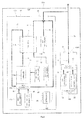
- Fig. 1 is a schematic diagram showing a schematic configuration of the power generation system according to Embodiment 1 of the present invention.
- a power generation system 100 As shown in Fig. 1 , a power generation system 100 according to Embodiment 1 of the present invention is provided inside a building 200.
- the power generation system 100 includes a fuel cell unit 101, a controller 102, a combustion unit 103, and a discharge passage 70.
- the fuel cell unit 101 includes a fuel cell 11, a hydrogen generator 14, and a case 12, and the combustion unit 103 includes a second combustor 17.
- the hydrogen generator 14 includes a first combustor 14b.
- the discharge passage 70 is formed so as to cause the case 12 of the fuel cell unit 101 and an exhaust port 103A of the combustion unit 103 to communicate with each other.
- the controller 102 causes one of the first combustor 14b and the second combustor 17 to perform the ignition operation, the controller 102 causes the flow rate of the exhaust gas discharged from the unit including the other combustor to become constant during the period of the ignition operation of the one combustor.
- Embodiment 1 has explained an example in which the power generation system 100 is provided inside the building 200.
- the power generation system 100 may be provided outside the building 200 as long as the discharge passage 70 causes the case 12 of the fuel cell unit 101 and the exhaust port 103A of the combustion unit 103 to communicate with each other (to be connected to each other).
- the fuel cell 11, the hydrogen generator 14, and an oxidizing gas supply unit 15 are provided inside the case 12 of the fuel cell unit 101.
- the controller 102 is also provided inside the case 12.
- the controller 102 is provided inside the case 12 of the fuel cell unit 101.
- the present embodiment is not limited to this.
- the controller 102 may be provided inside the combustion unit 103 or may be provided separately from the case 12 and the combustion unit 103.
- a hole 16 penetrating the wall in a thickness direction of the wall is formed.
- a pipe constituting the discharge passage 70 is inserted through the hole 16 such that a gap is formed between the hole 16 and the discharge passage 70.
- the gap between the hole 16 and the discharge passage 70 constitutes an air supply port 16. With this, the air outside the power generation system 100 is supplied through the air supply port 16 to the inside of the case 12.
- the hole through which the pipe constituting the discharge passage 70 is inserted and the hole constituting the air supply port 16 are configured as one hole 16.
- the hole through which the pipe constituting the discharge passage 70 is inserted and the hole constituting the air supply port 16 may be separately formed at the case 12.
- the air supply port 16 may be formed at the case 12 by a single hole or a plurality of holes.
- the hydrogen generator 14 includes a reformer 14a and the first combustor 14b.
- the reformer 14a generates the fuel gas from a hydrocarbon gas that is a material gas and steam.
- the first combustor 14b is configured to heat the reformer 14a.
- the first combustor 14b is constituted by a burner and includes an ignition unit, such as an ignitor, and an ignition detector, such as a flame rod (both not shown).
- a combustion fan (first air supply unit) 14c is connected to the first combustor 14b through an air supply passage 79.
- the combustion fan 14c may have any configuration as long as it can supply the combustion air to the first combustor 14b.
- the combustion fan 14c may be constituted by a fan, a blower, or the like.
- a first combustible gas supply unit 20 is connected to the first combustor 14b through a first combustible gas supply passage 81. Further, a downstream end of an off fuel gas passage 73 is connected to the first combustor 14b.
- the combustible gas such as the hydrocarbon gas
- the off fuel gas flows through the off fuel gas passage 73 to be supplied as the combustion fuel to the first combustor 14b.
- the first combustible gas supply unit 20 may have any configuration as long as it can supply the combustible gas to the first combustor 14b.
- the first combustible gas supply unit 20 may be constituted by a single pump or by a pump and a flow rate control valve.
- the combustible gas may be a natural gas, a LP gas, or the like.
- the combustion fan (first air supply unit) 14c is connected to the first combustor 14b through the air supply passage 79.
- the combustion fan 14c may have any configuration as long as it can supply the combustion air to the first combustor 14b.
- the combustion fan 14c may be constituted by a fan, a blower, or the like.
- the first combustor 14b combusts the supplied off fuel gas (or a first combustible gas) and the combustion air to generate a flue gas and heat.
- the flue gas generated by the first combustor 14b heats the reformer 14a and the like to be discharged to a flue gas passage 80.
- the flue gas discharged to the flue gas passage 80 flows through the flue gas passage 80 to be discharged to the discharge passage 70.
- the flue gas discharged to the discharge passage 70 flows through the discharge passage 70 to be discharged to the outside of the power generation system 100 (building 200).
- a material gas supply unit 21 and a water supply unit are connected to the reformer 14a, and the material gas and the water are supplied to the reformer 14a.
- a natural gas containing methane as a major component, a LP gas containing propane as a major component, or the like may be used as the material gas.
- the material gas supply unit 21 may have any configuration as long as it can supply the material gas to the reformer 14a.
- the material gas supply unit 21 may be constituted by a single pump or by a pump and a flow rate control valve.
- the water supplied from the water supply unit to the reformer 14a is heated along the way to become steam.
- the reformer 14a includes a reforming catalyst.
- the reforming catalyst may be any material as long as, for example, it can serve as a catalyst in a steam-reforming reaction by which the hydrogen-containing gas is generated from the material gas and the steam.
- Examples of the reforming catalyst include a ruthenium-based catalyst in which a catalyst carrier, such as alumina, supports ruthenium (Ru) and a nickel-based catalyst in which the same catalyst carrier as above supports nickel (Ni).
- a catalyst by which an autothermal reforming reaction can be performed may be used as the reforming catalyst of the reformer 14a.
- the hydrogen-containing gas is generated by the reforming reaction between the supplied material gas and water (steam).
- the generated hydrogen-containing gas flows as the fuel gas through a fuel gas supply passage 71 to be supplied to a fuel gas channel 11A of the fuel cell 11.
- Embodiment 1 the hydrogen-containing gas generated by the reformer 14a is supplied as the fuel gas to the fuel cell 11.
- the present embodiment is not limited to this.
- Embodiment 1 may be configured such that the hydrogen-containing gas flowed through a shift converter and carbon monoxide remover provided in the hydrogen generator 14 is supplied to the fuel cell 11, the shift converter including a shift catalyst (such as a copper-zinc-based catalyst) for reducing carbon monoxide in the hydrogen-containing gas supplied from the reformer 14a, the carbon monoxide remover including an oxidation catalyst (such as a ruthenium-based catalyst) and/or a methanation catalyst (such as a ruthenium-based catalyst).
- a shift catalyst such as a copper-zinc-based catalyst
- the carbon monoxide remover including an oxidation catalyst (such as a ruthenium-based catalyst) and/or a methanation catalyst (such as a ruthenium-based catalyst).
- the first combustible gas supply unit 20 is provided, and when starting up the fuel cell unit 101, the combustible gas is supplied from the first combustible gas supply unit 20 to the first combustor 14b.
- the present embodiment is not limited to this.
- the material gas supply unit 21 may also serve as the first combustible gas supply unit 20.
- the combustible gas herein, the material gas
- the material gas is supplied from the material gas supply unit 21 through the reformer 14a of the hydrogen generator 14, the fuel gas supply passage 71, the fuel gas channel 11 A of the fuel cell 11, and the off fuel gas passage 73 to the first combustor 14b.
- Embodiment 1 may be configured such that a bypass passage configured to connect the fuel gas supply passage 71 and the off fuel gas passage 73 is provided, and the material gas supply unit 21 serves as the first combustible gas supply unit 20.
- the combustible gas herein, the material gas
- the material gas may be supplied from the material gas supply unit 21 through the reformer 14a of the hydrogen generator 14, the fuel gas supply passage 71, the bypass passage, and the off fuel gas passage 73 to the first combustor 14b.
- the flow of the material gas from the fuel gas supply passage 71 to the bypass passage may be switched in such a manner that valves, such as three-way valves, are provided on respective passage and are opened or closed.
- the oxidizing gas supply unit 15 may have any configuration as long as it can supply the oxidizing gas (air) to the fuel cell 11 while adjusting the flow rate of the oxidizing gas.
- the oxidizing gas supply unit 15 may be constituted by a fan, a blower, or the like or by an oxygen bomb and a flow rate adjuster.
- the flow rate adjuster may be constituted by a single pump or by a pump and a flow rate control valve.
- the fuel cell 11 (to be precise, an inlet of an oxidizing gas channel 11 B of the fuel cell 11) is connected to the oxidizing gas supply unit 15 through an oxidizing gas supply passage 72.
- the fuel cell 11 includes an anode and a cathode (both not shown).
- the fuel gas supplied to the fuel gas channel 11A is supplied to the anode while the fuel gas flows through the fuel gas channel 11A.
- the oxidizing gas supplied to the oxidizing gas channel 11B is supplied to the cathode while the oxidizing gas flows through the oxidizing gas channel 11B. Then, the fuel gas supplied to the anode and the oxidizing gas supplied to the cathode react with each other to generate electricity and heat.
- the generated electricity is supplied to an external electric power load (such as a domestic electrical apparatus) by an electric power conditioner, not shown.
- the generated heat is recovered by a heat medium flowing through a heat medium channel, not shown.
- the heat recovered by the heat medium can be used to, for example, heat water. Or, only the electricity generated by the fuel cell 11 may be utilized, and the heat may be discarded.
- each of various fuel cells such as a polymer electrolyte fuel cell, a direct internal reforming type solid-oxide fuel cell, and an indirect internal reforming type solid-oxide fuel cell, may be used as the fuel cell 11.
- the fuel cell 11 and the hydrogen generator 14 are configured separately.
- the present embodiment is not limited to this.
- the hydrogen generator 14 and the fuel cell 11 may be configured integrally.
- the fuel cell 11 and the hydrogen generator 14 are configured as one unit covered with a common heat insulating material, and the first combustor 14b can heat not only the reformer 14a but also the fuel cell 11.
- the anode of the fuel cell 11 serves as the reformer 14a, so that the anode of the fuel cell 11 and the reformer 14a may be configured integrally. Further, since the configuration of the fuel cell 11 is similar to that of a typical fuel cell, a detailed explanation thereof is omitted.
- An upstream end of the off fuel gas passage 73 is connected to an outlet of the fuel gas channel 11A.
- a downstream end of the off fuel gas passage 73 is connected to the first combustor 14b.
- An upstream end of an off oxidizing gas passage 74 is connected to an outlet of the oxidizing gas channel 11B.
- a downstream end of the off oxidizing gas passage 74 is connected to the discharge passage 70.
- the fuel gas (hereinafter referred to as an "off fuel gas”) unconsumed in the fuel cell 11 is supplied from the outlet of the fuel gas channel 11A through the off fuel gas passage 73 to the first combustor 14b.
- the oxidizing gas (hereinafter referred to as an “off oxidizing gas”) unconsumed in the fuel cell 11 is discharged from the outlet of the oxidizing gas channel 11 B through the off oxidizing gas passage 74 to the discharge passage 70.
- the off oxidizing gas discharged to the discharge passage 70 flows through the discharge passage 70 to be discharged to the outside of the building 200.
- the off oxidizing gas is exemplified as the exhaust gas discharged from the fuel cell unit 101.
- the exhaust gas discharged from the fuel cell unit 101 is not limited to these gases.
- the exhaust gas discharged from the fuel cell unit 101 may be a gas (the flue gas, the hydrogen-containing gas, or the like) discharged from the hydrogen generator 14 or a gas (mainly air) in the case 12.
- the combustion unit 103 includes the second combustor 17 and a combustion fan (second air supply unit) 18.
- the second combustor 17 and the combustion fan 18 are connected to each other through a combustion air supply passage 76.
- the combustion fan 18 may have any configuration as long as it can supply the combustion air to the second combustor 17.
- the combustion fan 18 may be constituted by a fan, a blower, or the like.
- the second combustor 17 is constituted by a burner and includes an ignition unit, such as an ignitor, and an ignition detector, such as a flame rod (both not shown).
- a second combustible gas supply unit 22 is connected to the second combustor 17 through a second combustible gas supply passage 82.
- the second combustible gas supply unit 22 may be constituted by a single pump or by a pump and a flow rate control valve.
- a second combustible gas (combustion fuel) may be a natural gas, a LP gas, or the like.
- the second combustor 17 combusts the combustion air supplied from the combustion fan 18 and the combustion fuel supplied from the second combustible gas supply unit 22 to generate the heat and the flue gas.
- the generated heat can be used to heat water. That is, the combustion unit 103 may be used as a boiler.
- An upstream end of an exhaust gas passage 77 is connected to the second combustor 17, and a downstream end of the exhaust gas passage 77 is connected to the discharge passage 70.
- the flue gas generated by the second combustor 17 is discharged through the exhaust gas passage 77 to the discharge passage 70.
- the flue gas generated by the second combustor 17 is discharged to the discharge passage 70 as the exhaust gas discharged from the combustion unit 103. Then, the flue gas discharged to the discharge passage 70 flows through the discharge passage 70 to be discharged to the outside of the building 200.
- the exhaust gas discharged from the combustion unit 103 is not limited to the flue gas.
- the combustion air discharged to the discharge passage 70 in a case where only the combustion fan 18 is activated can also be exemplified as the exhaust gas.
- the combustion fuel discharged to the discharge passage 70 in a case where only a combustion fuel supply mit, not shown, is activated can also be exemplified as the exhaust gas.
- a hole 19 penetrating the wall in a thickness direction of the wall is formed.
- the pipe constituting the discharge passage 70 is inserted through the hole 19 such that a gap is formed between the hole 19 and the discharge passage 70.
- the gap between the hole 19 and the discharge passage 70 constitutes an air supply port 19. With this, the air outside the power generation system 100 is supplied through the air supply port 19 to the inside of the combustion unit 103.
- the discharge passage 70 branches, and two upstream ends thereof are respectively connected to the hole 16 and the hole 19.
- the discharge passage 70 is formed so as to extend to the outside of the building 200, and a downstream end (opening) thereof is open to the atmosphere.
- the discharge passage 70 causes the case 12 and the exhaust port 103A of the combustion unit 103 to communicate with each other.
- the hole through which the pipe constituting the discharge passage 70 is inserted and the hole constituting the air supply port 19 are configured as one hole 19.
- the hole through which the pipe constituting the discharge passage 70 is inserted (to which the pipe constituting the discharge passage 70 is connected) and the hole constituting the air supply port 19 may be separately formed at the combustion unit 103.
- the air supply port 19 may be formed at the combustion unit 103 by a single hole or a plurality of holes.
- the controller 102 may be any device as long as it controls respective devices constituting the power generation system 100.
- the controller 102 includes a calculation processing module, such as a microprocessor or a CPU, and a storage module, such as a memory, configured to store programs for executing respective control operations.
- the calculation processing module reads out and executes a predetermined control program stored in the storage module.
- the controller 102 processes the information and performs various control operations, such as the above control operations, regarding the power generation system 100.
- the controller 102 may be constituted by a single controller or may be constituted by a group of a plurality of controllers which cooperate to execute control operations of the power generation system 100.
- the controller 102 may be constituted by a microcomputer or may be constituted by a MPU, a PLC (Programmable Logic Controller), a logic circuit, or the like.
- the controller 102 is constituted by a single controller and controls respective devices constituting the power generation system 100.
- the controller 102 causes one of the combustors to perform the ignition operation
- the controller 102 causes the flow rate of the exhaust gas discharged from the unit including the other combustor to become constant during the period of the ignition operation of the one combustor.
- the controller 102 does not cause the other combustor to perform the ignition operation during the period of the ignition operation of the one combustor.
- the controller 102 causes one of the combustors to perform the ignition operation, and if the ignition operation command of the other combustor is input to the controller 102, the controller 102 causes the other combustor to perform the ignition operation after causing the one combustor to perform the ignition operation.
- "after causing the combustor to perform the ignition operation” denotes a state after the ignition of the combustor has been conformed.
- the ignition can be performed by, for example, a flame rod.
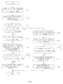
- Fig. 2 is a flow chart showing one example of the operation of the power generation system according to Embodiment 1.
- an activating command of the fuel cell unit 101 is input to the controller 102 (Step S101), and an activating command of the combustion unit 103 is input to the controller 102 (Step S102).
- Examples of the case where the activating commands of the fuel cell unit 101 and the combustion unit 103 are input to the controller 102 include a case where a user or the like of the power generation system 100 operates a remote controller, not shown in Fig. 1 , to instruct an operation start of the fuel cell unit 101 and the combustion unit 103 or a case where a preset operation start time of the power generation system 100 has come.
- the controller 102 temporarily stops an activation start of the combustion unit 103 (Step S103). Then, the controller 102 outputs an activation start command of the fuel cell unit 101 to respective devices constituting the fuel cell unit 101 (Step S104).
- the operation of the fuel cell unit 101 is started. Specifically, first, the combustion fan 14c is activated, so that the combustion air flows through the air supply passage 79 to be supplied to the first combustor 14b. Next, the ignition unit (not shown in Fig. 1 ) of the first combustor 14b is activated. Then, the first combustible gas supply unit 20 is activated, so that the combustible gas (combustion fuel) flows through the first combustible gas supply passage 81 to be supplied to the first combustor 14b.
- the first combustor 14b ignites the combustible gas and the combustion air to combust a fuel-air mixture of the combustible gas and the combustion air.
- Step S105 When an ignition detection of the first combustor 14b is input to the controller 102 by the ignition detector, not shown, of the first combustor 14b (Yes in Step S105), the controller 102 cancels the temporary stop of the activation start of the combustion unit 103 (Step S106). Next, the controller 102 outputs the activation start command of the combustion unit 103 to respective devices constituting the combustion unit 103 (Step S107).
- the combustion fan 18 is activated, so that the combustion air flows through the combustion air supply passage 76 to be supplied to the second combustor 17.
- the ignitor (not shown in Fig. 1 ) of the second combustor 17 is activated.
- the second combustible gas supply unit 22 is activated, so that the combustion fuel is supplied to the second combustor 17.
- the combustion fuel is supplied to the second combustor 17, the second combustor 17 ignites the combustion fuel and the combustion air to combust the fuel-air mixture of the combustion fuel and the combustion air.
- the hydrogen generator 14 In the fuel cell unit 101, after the ignition of the first combustor 14b, respective operations are performed, that is, for example, the hydrogen generator 14 generates the fuel gas to supply the fuel gas to the fuel gas channel 11A. Since these operations are the same as the electric power generating operations of a typical fuel cell, detailed explanations thereof are omitted.
- the combustion unit 103 the second combustor 17 starts the combustion to generate the flue gas. The generated flue gas is discharged to the discharge passage 70 to be discharged to the outside of the building 200 (power generation system 100).
- the start of the ignition operation of the second combustor 17 is temporarily stopped. With this, the stop state of the second combustor 17 is maintained, and the flow rate of the exhaust gas discharged from the combustion unit 103 to the discharge passage 70 can be caused to become constant (in this case, the flow rate of the exhaust gas is zero). On this account, the ignition operation of the first combustor 14b can be stably performed.
- Fig. 3 is a flow chart showing one example of the operation of the power generation system according to Embodiment 1.
- Step S201 the activating command of the combustion unit 103 is input to the controller 102
- Step S202 the activating command of the fuel cell unit 101 is input to the controller 102
- the controller 102 temporarily stops the activation start of the fuel cell unit 101 (Step S203). Then, the controller 102 outputs the activation start command of the combustion unit 103 to respective devices constituting the combustion unit 103 (Step S204).
- the combustion fan 18 is activated, so that the combustion air flows through the combustion air supply passage 76 to be supplied to the second combustor 17.
- the ignition unit (not shown in Fig. 1 ) of the second combustor 17 is activated.
- the second combustible gas supply unit 22 is activated, so that the combustion fuel is supplied to the second combustor 17.
- the combustion fuel is supplied to the second combustor 17, the second combustor 17 ignites the combustion fuel and the combustion air to combust the fuel-air mixture of the combustion fuel and the combustion air.
- Step S205 When an ignition detection of the second combustor 17 is input to the controller 102 by the ignition detector, not shown, of the second combustor 17 (Yes in Step S205), the controller 102 cancels the temporary stop of the activation start of the fuel cell unit 101 (Step S206). Next, the controller 102 outputs the activation start command of the fuel cell unit 101 to respective devices constituting the fuel cell unit 101 (Step S207).
- the operation of the fuel cell unit 101 is started. Specifically, first, the combustion fan 14c is activated, so that the combustion air flows through the air supply passage 79 to be supplied to the first combustor 14b. Next, the ignition unit (not shown in Fig. 1 ) of the first combustor 14b is activated. Then, the first combustible gas supply unit 20 is activated, so that the combustible gas (combustion fuel) flows through the first combustible gas supply passage 81 to be supplied to the first combustor 14b.
- the first combustor 14b ignites the combustible gas and the combustion air to combust the fuel-air mixture of the combustible gas and the combustion air.
- the hydrogen generator 14 In the fuel cell unit 101, after the ignition of the first combustor 14b, respective operations are performed, that is, for example, the hydrogen generator 14 generates the fuel gas to supply the fuel gas to the fuel gas channel 11A. Since these operations are the same as the electric power generating operations of a typical fuel cell, detailed explanations thereof are omitted.
- the combustion unit 103 the second combustor 17 starts the combustion to generate the flue gas. The generated flue gas is discharged to the discharge passage 70 to be discharged to the outside of the building 200 (power generation system 100).
- the start of the ignition operation of the first combustor 14b is temporarily stopped. With this, the stop state of the first combustor 14b is maintained, and the flow rate of the exhaust gas discharged from the fuel cell unit 101 to the discharge passage 70 can be caused to become constant (in this case, the flow rate of the exhaust gas is zero). On this account, the ignition operation of the second combustor 17 can be stably performed.
- the controller 102 controls the other combustor in the same manner as above. To be specific, until the ignition of one of the combustors is confirmed, the controller 102 temporarily stops the activation start of he other combustor. When the ignition of one of the combustors is confirmed, the controller 102 starts the ignition operation of the other combustor.
- the controller 102 In a case where the controller 102 causes one of the combustors to perform the ignition operation, the controller 102 maintains the operating state of the other combustor during the period of the ignition operation of the one combustor. Specifically, in a case where the controller 102 causes one of the combustors to perform the ignition operation, and if a command for changing a manipulation amount of the other combustor is input to the controller 102, the controller 102 does not change the manipulation amount of the other combustor during the period of the ignition operation of the one combustor.
- the controller 102 causes one of the combustors to perform the ignition operation, and if a command for changing the flow rate of the exhaust gas discharged from the other combustor is input to the controller 102, the controller 102 changes the flow rate of the exhaust gas discharged from the other combustor after causing the one combustor to perform the ignition operation.
- a manipulation amount change command of the second combustor 17 (a flow rate change command of the exhaust gas discharged from the second combustor 17) is input when the first combustor 14b is caused to perform the ignition operation
- a manipulation amount change command of the first combustor 14b (a flow rate change command of the exhaust gas discharged from the first combustor 14b) is input when the second combustor 17b is caused to perform the ignition operation
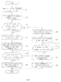
- Fig. 4 is a flow chart showing one example of the operation of the power generation system according to Embodiment 1.
- Step S301 the activating command of the fuel cell unit 101 is input to the controller 102
- Step S302 the manipulation amount change command of the combustion unit 103 is input to the controller 102
- the order of Steps S301 and S302 may be changed.
- the controller 102 temporarily stops the change in the manipulation amount of the combustion unit 103 (Step S303). Then, the controller 102 outputs the activation start command of the fuel cell unit 101 to respective devices constituting the fuel cell unit 101 (Step S304).
- the operation of the fuel cell unit 101 is started. Specifically, first, the combustion fan 14c is activated, so that the combustion air flows through the air supply passage 79 to be supplied to the first combustor 14b. Next, the ignition unit (not shown in Fig. 1 ) of the first combustor 14b is activated. Then, the first combustible gas supply unit 20 is activated, so that the combustible gas flows through the first combustible gas supply passage 81 to be supplied to the first combustor 14b.
- the first combustor 14b ignites the combustible gas and the combustion air to combust the fuel-air mixture of the combustible gas and the combustion air.
- Step S305 When the ignition detection of the first combustor 14b is input to the controller 102 by the ignition detector, not shown, of the first combustor 14b (Yes in Step S305), the controller 102 cancels the temporary stop of the change in the manipulation amount of the combustion unit 103 (Step S306). Next, the controller 102 outputs the manipulation amount change Command of the combustion unit 103 to respective devices constituting the combustion unit 103 (Step S307).
- a combustion amount of the second combustor 17 is changed. More specifically, the combustion amount of the second combustor 17 is changed by changing the manipulation amounts of the combustion fan 18 and the second combustible gas supply unit 22. With this, the flow rate of the exhaust gas discharged from the second combustor 17 changes.
- the change in the combustion amount of the second combustor 17 is temporarily stopped. With this, the operating state of the second combustor 17 is maintained, and the flow rate of the exhaust gas discharged from the combustion unit 103 to the discharge passage 70 can be caused to become constant (in this case, the flow rate of the exhaust gas is a predetermined flow rate (specifically, the flow rate of the exhaust gas is a flow rate before a command for changing the manipulation amount of the (combustion unit 103 is input)).
- the ignition operation of the first combustor 14b can be stably performed.
- Fig. 5 is a flow chart showing one example of the operation of the power generation system according to Embodiment 1.
- Step S401 the activating command of the combustion unit 103 is input to the controller 102
- Step S402 the manipulation amount change command of the fuel cell unit 101 (the electric power generation amount change command of the fuel cell 11) is input to the controller 102
- Step S402 the order of Steps S401 and S402 may be changed.
- the controller 102 temporarily stops the change in the manipulation amount of the fuel cell unit 101 (Step S403). Then, the controller 102 outputs the activation start command of the combustion unit 103 to respective devices constituting the combustion unit 103 (Step S404).
- the combustion fan 18 is activated, so that the combustion air flows through the combustion air supply passage 76 to be supplied to the second combustor 17.
- the ignition unit (not shown in Fig. 1 ) of the second combustor 17 is activated.
- the second combustible gas supply unit 22 is activated, so that the combustion fuel is supplied to the second combustor 17.
- the combustion fuel is supplied to the second combustor 17, the second combustor 17 ignites the combustion fuel and the combustion air to combust the fuel-air mixture of the combustion fuel and the combustion air.
- Step S405 When the ignition detection of the second combustor 17 is input to the controller 102 by the ignition detector, not shown, of the second combustor 17 (Yes in Step S405), the controller 102 cancels the temporary stop of the change in the manipulation amount of the fuel cell unit 101 (Step S406). Next, the controller 102 outputs the manipulation amount change command of the fuel cell unit 101 to respective devices constituting the fuel cell unit 101 (Step S407).
- the electric power generation amount of the fuel cell 11 is changed. More specifically, the flow rate of the fuel gas generated by the hydrogen generator 14 and the flow rate of the oxidizing gas supplied from the oxidizing gas supply unit 15 to the fuel cell 11 are changed. To change the flow rate of the fuel gas generated by the hydrogen generator 14, the manipulation amounts of the material gas supply unit 21, the water supply unit (not shown), and the combustion fan 14c are changed.
- the change in the manipulation amount of the fuel cell unit 101 (the change in the electric power generation amount of the fuel cell 11) is temporarily stopped.
- the operating state of the fuel cell unit 101 is maintained, and the flow rate of the exhaust gas discharged from the fuel cell unit 101 to the discharge passage 70 can be caused to become constant (in this case, the flow rate of the exhaust gas is a predetermined flow rate (specifically, the flow rate of the exhaust gas is a flow rate before a command for changing the manipulation amount of the fuel cell unit 101 is input)).
- the ignition operation of the second combustor 17 can be stably performed.
- the power generation system 100 according to Embodiment 1 configured as above is configured such that during the period of the ignition operation of one of the combustors, the flow rate of the exhaust gas discharged from the unit including the other combustor is caused to become constant. Therefore, even if a command for changing the operating state of the unit including the other combustor is output, the ignition operation of the one combustor can be stably performed.
- the power generation system is configured such that: the fuel cell unit includes a ventilator configured to ventilate the inside of the case by discharging a gas in the case to the discharge passage; and in a case where the controller causes the second combustor to perform the ignition operation, the controller does not change the manipulation amount of the ventilator during the period of the ignition operation of the second combustor.
- Fig. 6 is a schematic diagram showing a schematic configuration of the power generation system according to Embodiment 2 of the present invention.
- the power generation system 100 according to Embodiment 2 of the present invention is the same in basic configuration as the power generation system 100 according to Embodiment 1 but is different from the power generation system 100 according to Embodiment 1 regarding the configuration of the fuel cell unit 101.
- a ventilation fan (ventilator) 13 is provided in the case 12.
- the ventilation fan 13 is connected to the discharge passage 70 through a ventilation passage 75.
- the ventilation fan 13 may have any configuration as long as it can ventilate the inside of the case 12. With this, the air outside the power generation system 100 is supplied through the air supply port 16 to the inside of the case 12, and the ventilation fan 13 is activated, so that the gas (mainly air) inside the case 12 is discharged through the ventilation passage 75 and the discharge passage 70 to the outside of the building 200. Thus, the inside of the case 12 is ventilated.
- a fan is used as the ventilator.
- the present embodiment is not limited to this, and a blower may be used as the ventilator.
- the ventilation fan 13 is provided inside the case 12.
- the present embodiment is not limited to this.
- the ventilation fan 13 may be provided inside the discharge passage 70. In this case, it is preferable that the ventilation fan 13 be provided upstream of a branch portion of the discharge passage 70.
- the controller 102 causes the flow rate of the exhaust gas discharged from the fuel cell unit 101 to become constant during the period of the ignition operation of the second combustor 17. Specifically, when the controller 102 causes the second combustor 17 to perform the ignition operation, the controller 102 does not change the manipulation amount of the ventilation fan 13 during the period of the ignition operation of the second combustor 17.
- the control of the ventilation fan 13 and the second combustor 17 by the controller 102 will be specifically explained in reference to Figs. 6 to 8 .
- Fig. 7 is a flow chart showing one example of the operation of the power generation system according to Embodiment 2.
- Step S501 the activating command of the combustion unit 103 is input to the controller 102
- Step S502 the activating command of the ventilation fan 13 is input to the controller 102
- the controller 102 temporarily stops the activation start of the ventilation fan 13 (Step S503). Then, the controller 102 outputs the activation start command of the combustion unit 103 to respective devices constituting the combustion unit 103 (Step S504).
- the combustion fan 18 is activated, so that the combustion air flows through the combustion air supply passage 76 to be supplied to the second combustor 17.
- the ignition unit (not shown in Fig. 1 ) of the second combustor 17 is activated.
- the second combustible gas supply unit 22 is activated, so that the combustion fuel is supplied to the second combustor 17.
- the combustion fuel is supplied to the second combustor 17, the second combustor 17 ignites the combustion fuel and the combustion air to combust the fuel-air mixture of the combustion fuel and the combustion air.
- Step S505 When the ignition detection of the second combustor 17 is input to the controller 102 by the ignition detector, not shown, of the second combustor 17 (Yes in Step S505), the controller 102 cancels the temporary stop of the activation start of the ventilation fan 13 (Step S506). Next, the controller 102 outputs the activation start command to the ventilation fan 13 (Step S507).
- the ventilation fan 13 is activated, so that the gas (mainly air) in the case 12 is discharged through the ventilation passage 75 to the discharge passage 70 to be discharged to the outside of the building 200 (power generation system 100).
- the activation start of the ventilation fan 13 is temporarily stopped. With this, the stop state of the ventilation fan 13 is maintained, and the flow rate of the exhaust gas discharged from the fuel cell unit 101 to the discharge passage 70 can be caused to become constant (in this case, the flow rate of the exhaust gas is zero). On this account, the ignition operation of the second combustor 17 can be stably performed.
- Fig. 8 is a flow chart showing one example of the operation of the power generation system according to Embodiment 2.
- Step S601 the activating command of the combustion unit 103 is input to the controller 102 (Step S601), and the manipulation amount change command of the ventilation fan 13 is input to the controller 102 (Step S602).
- Step S602 the order of Steps S601 and S602 may be changed.
- the controller 102 temporarily stops the change in the manipulation amount of the ventilation fan 13 (Step S603). Then, the controller 102 outputs the activation start command of the combustion unit 103 to respective devices constituting the combustion unit 103 (Step S604).
- the combustion fan 18 is activated, so that the combustion air flows through the combustion air supply passage 76 to be supplied to the second combustor 17.
- the ignition unit (not shown in Fig. 1 ) of the second combustor 17 is activated.
- the second combustible gas supply unit 22 is activated, so that the combustion fuel is supplied to the second combustor 17.
- the combustion fuel is supplied to the second combustor 17, the second combustor 17 ignites the combustion fuel and the combustion air to combust the fuel-air mixture of the combustion fuel and the combustion air.
- Step S605 When the ignition detection of the second combustor 17 is input to the controller 102 by the ignition detector, not shown, of the second combustor 17 (Yes in Step S605), the controller 102 cancels the temporary stop of the change in the manipulation amount of the ventilation fan 13 (Step S606). Next, the controller 102 outputs the manipulation amount change command to the ventilation fan 13 (Step S607).
- the second combustor 17 pertorms the ignition operation, the change in the manipulation amounts of the ventilation fan 13 is temporarily stopped. With this, the operating state of the ventilation fan 13 is maintained, and the flow rate of the exhaust gas discharged from the ventilation fan 13 to the discharge passage 70 can be caused to become constant (in this case, the flow rate of the exhaust gas is a predetermined flow rate (specifically, the flow rate of the exhaust gas is a flow rate before a command for changing the manipulation amount of the ventilation fan 13 is input)). On this account, the ignition operation of the second combustor 17 can be stably performed.
- the power generation system 100 according to Embodiment 2 configured as above can also obtain the same operational advantages as the power generation system 100 according to Embodiment 1.
- Embodiment 2 has explained the control of the ventilation fan 13 and the combustion unit 103 by the controller 102 in a case where the manipulation amount of the ventilation fan 13 changes when the manipulation amount of the fuel cell unit 101 (the electric power generation amount of the fuel cell 11) is not changing (that is, in a case where the manipulation amount of the ventilation fan 13 changes regardless of the manipulation amount of the fuel cell unit 101).
- the control of the ventilation fan 13 and the combustion unit 103 by the controller 102 is not limited to this.
- the controller 102 may operate in the same manner as the power generation system 100 according to Embodiment 1.
- the controller 102 may be configured to control the manipulation amount of the ventilation fan 13 when controlling the manipulation amount of the fuel cell unit 101.
- the power generation system is configured such that: the fuel cell unit includes a ventilator configured to ventilate an inside of the fuel cell unit by discharging a gas in the fuel cell unit to the discharge passage, an oxidizing gas supply unit configured to supply the oxidizing gas to a cathode of the fuel cell, a first air supply unit configured to supply air to the first combustor, and a first combustible gas supply unit configured to supply the combustible gas to the first combustor; the discharge passage is configured such that a gas in the case, an off oxidizing gas discharged from the cathode, and an off combustion gas discharged from the first combustor are discharged to the atmosphere; and in a case where the controller changes an electric power generation amount of the fuel cell unit during the period of the ignition operation of the second combustor, the controller changes manipulation amounts of the ventilator, the oxidizing gas supply unit, the first air supply unit, and the first combustible gas supply unit to cause the flow
- the controller in a case where the controller increases the electric power generation amount of the fuel cell unit during the period of the ignition operation of the second combustor, the controller may increase the manipulation amounts of the oxidizing gas supply unit, the first air supply unit, and the first combustible gas supply unit and decrease the manipulation amount of the ventilator, and in a case where the controller decreases the electric power generation amount of the fuel cell unit during the period of the ignition operation of the second combustor, the controller may decrease the manipulation amounts of the oxidizing gas supply unit, the first air supply unit, and the first combustible gas supply unit and increase the manipulation amount of the ventilator.
- Embodiment 3 Since the configuration of the power generation system according to Embodiment 3 is the same as the configuration of the power generation system according to Embodiment 2, a detailed explanation thereof is omitted.
- the controller 102 changes the electric power generation amount of the fuel cell unit 101 during the period of the ignition operation of the second combustor 17, the controller 102 changes the manipulation amounts of the ventilation fan 13, the first combustible gas supply unit 20, the oxidizing gas supply unit 15, and the combustion fan 14c to cause the flow rate of the exhaust gas discharged from the fuel cell unit 101 to become constant.
- the control of the fuel cell unit 101 and the combustion unit 103 by the controller 102 will be specifically explained in reference to Figs. 9 and 10 .
- the manipulation amount of the material gas supply unit 21 is changed instead of the first combustible gas supply unit 20.
- Fig. 9 is a flow chart showing one example of the operation of the power generation system according to Embodiment 3.
- Step S701 when the activating command of the combustion unit 103 is input to the controller 102 during the operation of the fuel cell unit 101 (Step S701), the controller 102 outputs the activation start command of the combustion unit 103 to respective devices constituting the combustion unit 103 (Step S702).
- the combustion fan 18 is activated, so that the combustion air flows through the combustion air supply passage 76 to be supplied to the second combustor 17.
- the ignition unit (not shown in Fig. 6 ) of the second combustor 17 is activated.
- the second combustible gas supply unit 22 is activated, so that the combustion fuel is supplied to the second combustor 17.
- the ignition operation of the second combustor 17 is performed.
- Step S703 a command for increasing the electric power generation amount of the fuel cell unit 101 is input to the controller 102 (Step S703).
- the controller 102 outputs a command for increasing the manipulation amounts of the first combustible gas supply unit 20 (or the material gas supply unit 21), the oxidizing gas supply unit 15, and the combustion fan 14c and a command for decreasing the manipulation amount of the ventilation fan 13 (Step S704).
- the controller 102 controls increased amounts of the manipulation amounts of the first combustible gas supply unit 20 (or the material gas supply unit 21), the oxidizing gas supply unit 15, and the combustion fan 14c and a decreased amount of the manipulation amount of the ventilation fan 13 such that the flow rate of the exhaust gas discharged from the fuel cell unit 101 becomes constant.
- Step S705 When the ignition detection of the second combustors 17 is input to the controller 102 by the ignition detector (not shown in Fig. 6 ) of the second combustor 17 (Yes in Step S705), the controller 102 outputs a command for increasing the manipulation amount to the ventilation fan 13 (Step S706). With this, the inside of the case 12 can be adequately ventilated.
- Fig. 10 is a flow chart showing one example of the operation of the power generation system according to Embodiment 3.
- Step S801 in a case where the activating command of the combustion unit 103 is input to the controller 102 during the operation of the fuel cell unit 101 (Step S801), the controller 102 outputs the activation start command of the combustion unit 103 to respective devices constituting the combustion unit 103 (Step S802).
- the combustion fan 18 is activated, so that the combustion air flows through the combustion air supply passage 76 to be supplied to the second combustor 17.
- the ignition unit (not shown in Fig. 6 ) of the second combustor 17 is activated.
- the second combustible gas supply unit 22 is activated, so that the combustion fuel is supplied to the second combustor 17.
- the ignition operation of the second combustor 17 is performed.
- Step S803 a command for decreasing the electric power generation amount of the fuel cell unit 101 1 is input to the controller 102 (Step S803).
- the controller 102 outputs a command for decreasing the manipulation amounts of the material gas supply unit 21, the oxidizing gas supply unit 15, the first combustible gas supply unit 20, and the combustion fan 14c and a command for increasing the manipulation amount of the ventilation fan 13 (Step S804).
- the controller 102 controls decreased amounts of the manipulation amounts of the first combustible gas supply unit 20 (or the material gas supply unit 21), the oxidizing gas supply unit 15, and the combustion fan 14c and an increased amount of the manipulation amount of the ventilation fan 13 such that the flow rate of the exhaust gas discharged from the fuel cell mit 101 becomes constant.
- Step S805 When the ignition detection of the second combustor 17 is input to the controller 102 by the ignition detector (not shown in Fig. 6 ) of the second combustor 17 (Yes in Step S805), the controller 102 outputs a command for decreasing the manipulation amount to the ventilation fan 13 (Step S806). With this, unnecessary consumption of electric power can be suppressed.
- the flow rate of the exhaust gas discharged from the fuel cell unit 101 is caused to become constant, so that the ignition operation of the second combustor 17 can be stably performed.
- the power generation system is configured such that: the combustion unit includes a second combustible gas supply unit configured to supply the combustible gas to the second combustor, and a second air supply unit configured to supply air to the second combustor; in a case where the controller, increases a combustion amount of the combustion unit during the period of the ignition operation of the first combustor, the controller increases a manipulation amount of the second combustible gas supply unit and decreases the manipulation amount of the second air supply unit; and in a case where the controller decreases the combustion amount of the combustion unit during the period of the ignition operation of the first combustor, the controller decreases the manipulation amount of the second combustible gas supply unit and increases the manipulation amount of the second air supply unit.
- the manipulation amount of the second combustible gas supply unit is increased and the manipulation amount of the second air supply unit is decreased within such a range that the combustion failure does not occur in the second combustor of the combustion unit or the carbon monoxide is not generated in the second combustor of the combustion unit.
- the manipulation amount of the second combustible gas supply unit is decreased and the manipulation amount of the second air supply unit is increased within such a range that the combustion failure does not occur in the second combustor of the combustion unit or the carbon monoxide is not generated in the second combustor of the combustion unit.
- Embodiment 4 Since the configuration of the power generation system according to Embodiment 4 is the same as each of the configurations of the power generation systems according to Embodiments 1 and 2, a detailed explanation thereof is omitted.
- the controller 102 changes the combustion amount of the combustion unit 103 during the period of the ignition operation of the first combustor 14b, the controller 102 changes the manipulation amounts of the second combustible gas supply unit 22 and the combustion fan 18 to cause the flow rate of the exhaust gas discharged from the combustion unit 103 to become constant.
- the control of the fuel cell unit 101 and the combustion unit 103 by the controller 102 will be specifically explained in reference to Figs. 11 and 12 .
- Fig. 11 is a flow chart showing one example of the operation of the power generation system according to Embodiment 4.
- Step S11 when the activating command of the fuel cell unit 101 is input to the controller 102 during the operation of the combustion unit 103 (Step S11), the controller 102 outputs the activation start command of the fuel cell unit 101 to respective devices constituting the fuel cell unit 101 (Step S12).
- the operation of the fuel cell unit 101 is started. Specifically, first, the combustion fan 14c is activated, so that the combustion air flows through the air supply passage 79 to be supplied to the first combustor 14b. Next, the ignition unit (not shown in Figs. 1 and 6 ) of the first combustor 14b is activated. Then, the first combustible gas supply unit 20 is activated, so that the combustible gas (combustion fuel) is supplied to the first combustor 14b. Thus, the ignition operation of the first combustor 14b is performed.
- a command for increasing the combustion amount of the combustion unit 103 (second combustor 17) is input to the controller 102 (Step S13). Then, the controller 102 outputs a command for increasing the manipulation amount of the second combustible gas supply unit 22 and a command for decreasing the manipulation amount of the combustion fan 18 (Step S14).
- the controller 102 controls an increased amount of the manipulation amount of the second combustible gas supply unit 22 and a decreased amount of the manipulation amount of the combustion fan 18 such that the flow rate of the exhaust gas discharged from the combustion unit 103 becomes constant.
- the controller 102 controls the second combustible gas supply unit 22 and the combustion fan 18 such that the manipulation amount of the second combustible gas supply unit 22 is increased and the manipulation amount of the combustion fan 18 is decreased within such a range that the combustion failure does not occur in the second combustor 17 or the carbon monoxide is not generated in the second combustor 17 (an air-fuel ratio falls within such a range that the combustion in the second combustor 17 can be continued).
- Step S15 when the ignition detection of the first combustor 14b is input to the controller 102 by the ignition detector (not shown in Figs. 1 and 6 ) of the first combustor 14b (Yes in Step S15), the controller 102 outputs the command for increasing the manipulation amount to the combustion fan 18 (Step S16). With this, the combustion in the second combustor 17 can be more stably performed.
- the controller 102 increases the manipulation amount of the combustion fan 18 in Step S16.
- the present embodiment is not limited to this.
- the controller 102 may decrease the manipulation amount of the second combustible gas supply unit 22 in Step S16.
- Fig. 12 is a flow chart showing one example of the operation of the power generation system according to Embodiment 4.
- Step S21 when the activating command of the fuel cell unit 101 is input to the controller 102 during the operation of the combustion unit 103 (Step S21), the controller 102 outputs the activation start command of the fuel cell unit 101 to respective devices constituting the fuel cell unit 101 (Step S22).
- the operation of the fuel cell unit 101 is started. Specifically, first, the combustion fan 14c is activated, so that the combustion air flows through the air supply passage 79 to be supplied to the first combustor 14b. Next, the ignition unit (not shown in Figs. 1 and 6 ) of the first combustor 14b is activated. Then, the first combustible gas supply unit 20 is activated, so that the combustible gas (combustion fuel) is supplied to the first combustor 14b. Thus, the ignition operation of the first combustor 14b is performed.
- a command for decreasing the combustion amount of the combustion unit 103 (second combustor 17) is input to the controller 102 (Step S23). Then, the controller 102 outputs a command for decreasing the manipulation amount of the second combustible gas supply unit 22 and a command for increasing the manipulation amount of the combustion fan 18 (Step S24).
- the controller 102 controls a decreased amount of the manipulation amount of the second combustible gas supply unit 22 and an increased amount of the manipulation amount of the combustion fan 18 such that the flow rate of the exhaust gas discharged from the combustion unit 103 becomes constant.
- the controller 102 controls the second combustible gas supply unit 22 and the combustion fan 18 such that the manipulation amount of the second combustible gas supply unit 22 is decreased and the manipulation amount of the combustion fan 18 is increased within such a range that the combustion failure does not occur in the second combustor 17 or the carbon monoxide is not generated in the second combustor 17 (the air-fuel ratio falls within such a range that the combustion in the second combustor 17 can be continued).
- Step S25 when the ignition detection of the first combustor 14b is input to the controller 102 by the ignition detector (not shown in Figs. 1 and 6 ) of the first combustor 14b (Yes in Step S25), the controller 102 outputs a command for increasing the manipulation amount to the second combustible gas supply unit 22 (Step S26). With this, the combustion in the second combustor 17 can be more stably performed.
- the controller 102 increases the manipulation amount of the second combustible gas supply unit 22 in Step S26.
- the present embodiment is not limited to this.
- the controller 102 may decrease the manipulation amount of the combustion fan 18 in Step S26.
- the flow rate of the exhaust gas discharged from the combustion unit 103 is caused to become constant, so that the ignition operation of the first combustor 14b can be stably performed.
- the power generation system is configured such that: the fuel cell unit includes a first combustible gas supply unit configured to supply the combustible gas to the first combustor, and a first air supply unit configured to supply air to the first combustor; the combustion unit includes a second combustible gas supply unit configured to supply the combustible gas to the second combustor, and a second air supply unit configured to supply the air to the second combustor; the controller prestores a first threshold that is an air-fuel ratio higher than one and equal to or lower than two; and in a case where the air-fuel ratio of the other combustor is equal to or higher than the first threshold, and the controller causes the one combustor to perform the ignition operation, and if a command for increasing a manipulation amount of the other combustor is input to the controller, the controller causes the flow rate of the exhaust gas discharged from the other combustor to become constant by increasing the manipulation amount of the combustible
- the air-fuel ratio is a ratio of the air to the combustible gas and is determined based on the combustion reaction.
- the air-fuel ratio is one when the combustible gas completely combusts together with oxygen in the air in just proportion.
- the amount of air supplied is 1.5 times the amount of air necessary when the combustible gas completely combusts.
- a first threshold is set to be higher than a lower limit of the air-fuel ratio by a predetermined amount.
- the power generation system may be configured such that: the fuel cell unit includes a first combustible gas supply unit configured to supply the combustible gas to the first combustor, and a first air supply unit configured to supply air to the first combustor; the combustion unit includes a second combustible gas supply unit configured to supply the combustible gas to the second combustor, and a second air supply unit configured to supply the air to the second combustor; the controller prestores a first threshold that is an air-fuel ratio higher than one and equal to or lower than two; and in a case where the air-fuel ratio of the other combustor is lower than the first threshold, and the controller causes the one combustor to perform the ignition operation, and if a command for increasing a manipulation amount of the other combustor is input to the controller, the controller causes the one combustor to perform the ignition operation, and then increases a combustion amount of the other combustor.
- Embodiment 5 Since the configuration of the power generation system according to Embodiment 5 is the same as each of the configurations of the power generation systems according to Embodiments 1 and 2, a detailed explanation thereof is omitted.
- Fig. 13 is a flow chart showing one example of the operation of the power generation system according to Embodiment 5.
- the activating command of the fuel cell unit 101 is input to the controller 102 during the operation of the combustion unit 103 (Step S31), and the command for increasing the combustion amount of the combustion unit 103 (the combustion amount of the second combustor 17) is input to the controller 102 (Step S32).
- the controller 102 confirms whether or not the air-fuel ratio of the second combustor 17 is equal to or higher than the first threshold (Step S33).
- the controller 102 proceeds to Step S34.
- the controller 102 proceeds to Step S38.
- Step S34 the controller 102 outputs the activating command of the fuel cell unit 101.
- the combustion fan 14c is activated, so that the combustion air flows through the air supply passage 79 to be supplied to the first combustor 14b.
- the ignition unit (not shown in Figs. 1 and 6 ) of the first combustor 14b is activated.
- the first combustible gas supply unit 20 is activated, so that the combustible gas (combustion fuel) is supplied to the first combustor 14b.
- the ignition operation of the first combustor 14b is performed.
- the controller 102 outputs the command for increasing the manipulation amount of the second combustible gas supply unit 22 and the command for decreasing the manipulation amount of the combustion fan 18 (Step S35). This is because when the air-fuel ratio of the second combustor 17 is equal to or higher than the first threshold, the air is being adequately supplied to the second combustor 17, so that the manipulation amount of the combustion fan 18 can be decreased. Specifically, the controller 102 increases the manipulation amount of the second combustible gas supply unit 22 and decreases the manipulation amount of the combustion fan 18 such that the air-fuel ratio of the second combustor 17 becomes equal to or higher than one, preferably, equal to or higher than the first threshold. With this, the flow rate of the exhaust gas discharged from the combustion unit 103 can be caused to become constant.
- Step S36 When the ignition detection of the first combustor 14b is input to the controller 102 by the ignition detector (not shown in Figs. 1 and 6 ) of the first combustor 14b (Yes in Step S36), the controller outputs the command for increasing the manipulation amount to the combustion fan 18 (Step S37). With this, the combustion in the second combustor 17 can be more stably performed.
- Step S38 the controller 102 temporarily stops the increase in the combustion amount of the combustion unit 103. This is because when the air-fuel ratio of the second combustor 17 is lower than the first threshold, the amount of remaining air unconsumed in the combustion in the second combustor 17 is small, so that it is not easy to decrease the manipulation amount of the combustion fan 18.
- the controller 102 outputs the activation start command of the fuel cell unit 101 to respective devices constituting the fuel cell unit 101 (Step S39).
- the operation of the fuel cell unit 101 is started. Specifically, first, the combustion fan 14c is activated, so that the combustion air flows through the air supply passage 79 to be supplied to the first combustor 14b. Next, the ignition unit (not shown in Figs. 1 and 6 ) of the first combustor 14b is activated. Then, the first combustible gas supply unit 20 is activated, so that the combustible gas (combustion fuel) is supplied to the first combustor 14b.
- the first combustor 14b ignites the combustible gas and the combustion air to combust the fuel-air mixture of the combustible gas and the combustion air.
- Step S40 When the ignition detection of the first combustor 14b is input to the controller 102 by the ignition detector (not shown in Figs. 1 and 6 ) of the first combustor 14b (Yes in Step S40), the controller 102 cancels the temporary stop of the increase in the combustion amount of the combustion unit 103 (Step S41). Next, the controller 102 outputs the command for increasing the combustion amount of the combustion unit 103 to respective devices constituting the combustion unit 103 (Step S42).
- the change in the combustion amount of the second combustor 17 is temporarily stopped when the first combustor 14b performs the ignition operation. With this, the operating state of the second combustor 17 is maintained, and the flow rate of the exhaust gas discharged from the combustion unit 103 to the discharge passage 70 can be caused to become constant. On this account, the ignition operation of the first combustor 14b can be stably performed.
- the power generation system 100 according to Embodiment 5 configured as above can stably perform the ignition operation of the first combustor 14b or the second combustor 17.
- the power generation system is configured such that: the fuel cell unit includes a first combustible gas supply unit configured to supply the combustible gas to the first combustor, and a first air supply unit configured to supply air to the first combustor; the combustion unit includes a second combustible gas supply unit configured to supply the combustible gas to the second combustor, and a second air supply unit configured to supply the air to the second combustor; the controller prestores a second threshold that is an air-fuel ratio within such a range that combustion in the other combustor is continued and is an air-fuel ratio higher than two; and in a case where the air-fuel ratio of the other combustor is the second threshold, and the controller causes the one combustor to perform the ignition operation, and if a command for decreasing a combustion amount of the other combustor is input to the controller, the controller causes the air-fuel ratio of the other combustor to become higher than one and equal to
- the power generation system may be configured such that: the fuel cell unit includes a first combustible gas supply unit configured to supply the combustible gas to the first combustor, and a first air supply unit configured to supply air to the first combustor; the combustion unit includes a second combustible gas supply unit configured to supply the combustible gas to the second combustor, and a second air supply unit configured to supply the air to the second combustor; the controller prestores a second threshold that is an air-fuel ratio within such a range that combustion in the other combustor is continued and is an air-fuel ratio higher than two; and in a case where the air-fuel ratio of the other combustor is higher than the second threshold, and the controller causes the one combustor to perform the ignition operation, and if a command for decreasing a manipulation amount of the other combustor is input to the controller, the controller causes the one combustor to perform the ignition operation, and then decreases a combustion amount of
- the second threshold of the air-fuel ratio may be higher than two and equal to or lower than three.
- the second threshold is set to be lower than an upper limit of the air-fuel ratio by a predetermined amount.
- Embodiment 6 Since the configuration of the power generation system according to Embodiment 6 is the same as each of the configurations of the power generation systems according to Embodiments 1 and 2, a detailed explanation thereof is omitted.
- Fig. 14 is a flow chart showing one example of the operation of the power generation system according to Embodiment 6.
- the activating command of the fuel cell unit 101 is input to the controller 102 during the operation of the combustion unit 103 (Step S51), and the command for decreasing the combustion amount of the combustion unit 103 (the combustion amount of the second combustor 17) is input to the controller 102 (Step S52).
- the controller 102 confirms whether or not the air-fuel ratio of the second combustor 17 is higher than the second threshold (Step S53). When the air-fuel ratio of the second combustor 17 is equal to or lower than the second threshold (No in Step S53), the controller 102 proceeds to Step S54. When the air-fuel ratio of the second combustor 17 is higher than the second threshold (Yes in Step S53), the controller 102 proceeds to Step S58.
- Step S54 the controller 102 outputs the activating command of the fuel cell unit 101.
- the combustion fan 14c is activated, so that the combustion air flows through the air supply passage 79 to be supplied to the first combustor 14b.
- the ignition unit (not shown in Figs. 1 and 6 ) of the first combustor 14b is activated.
- the material gas supply unit 21 is activated, so that the material gas (combustion fuel) is supplied to the first combustor 14b.
- the ignition operation of the first combustor 14b is performed.
- the controller 102 outputs the command for decreasing the manipulation amount of the second combustible gas supply unit 22 and the command for increasing the manipulation amount of the combustion fan 18 (Step S55). This is because when the air-fuel ratio of the second combustor 17 is equal to or lower than the second threshold, the manipulation amount of the second combustible gas supply unit 22 can be decreased and the manipulation amount of the combustion fan 18 can be increased within such a range that the combustion in the second combustor 17 can be continued.
- the controller 102 decreases the manipulation amount of the second combustible gas supply unit 22 and increases the manipulation amount of the combustion fan 18 such that, for example, the air-fuel ratio of the second combustor 17 becomes higher than two and equal to or lower than three (the air-fuel ratio of the second combustor 17 becomes higher than one and equal to or lower than the second threshold). With this, the flow rate of the exhaust gas discharged from the combustion unit 103 can be caused to become constant.
- Step S57 When the ignition detection of the first combustor 14b is input to the controller 102 by the ignition detector (not shown in Figs. 1 and 6 ) of the first combustor 14b (Yes in Step S56), the controller outputs the command for decreasing the manipulation amount to the combustion fan 18 (Step S57). With this, the combustion in the second combustor 17 can be more stably performed.
- Step S58 the controller 102 temporarily stops the decrease in the combustion amount of the combustion unit 103.
- the air-fuel ratio of the second combustor 17 is higher than the second threshold, a case where the combustion in the second combustor 17 cannot be continued can be avoided by changing the manipulation amounts of the second combustible gas supply unit 22 and the combustion fan 18.
- the controller 102 outputs the activation start command of the fuel cell unit 101 to respective devices constituting the fuel cell unit 101 (Step S59).
- the operation of the fuel cell unt 101 is started. Specifically, first, the combustion fan 14c is activated, so that the combustion air flows through the air supply passage 79 to be supplied to the first combustor 14b.
- the ignition unit (not shown in Figs. 1 and 6 ) of the first combustor 14b is activated.
- the first combustible gas supply unit 20 is activated, so that the combustible gas (combustion fuel) is supplied to the first combustor 14b.
- the first combustor 14b ignites the combustible gas and the combustion air to combust the fuel-air mixture of the combustible gas and the combustion air.
- Step S60 When the ignition detection of the first combustor 14b is input to the controller 102 by the ignition detector (not shown in Figs. 1 and 6 ) of the first combustor 14b (Yes in Step S60), the controller 102 cancels the temporary stop of the decrease in the combustion amount of the combustion unit 103 (Step S61). Next, the controller 102 outputs the command for decreasing the combustion amount of the combustion unit 103 to respective devices (the first combustible gas supply unit 20 and the combustion fan 18) constituting the combustion unit 103 (Step S42).
- the change in the combustion amount of the second combustor 17 is temporarily stopped when the first combustor 14b performs the ignition operation.
- the operating state of the second combustor 17 is maintained, and the flow rate of the exhaust gas discharged from the combustion unit 103 to the discharge passage 70 can be caused to become constant.
- the ignition operation of the first combustor 14b can be stably performed.
- the power generation system 100 according to Embodiment 6 configured as above can stably perform the ignition operation of the first combustor 14b or the second combustor 17.
- the ignition operation of one of the combustors can be stably performed even in a case where a command for changing the operating state of the unit including the other combustor is output. Therefore, the power generation system of the present invention and the method of operating the power generation system are useful.
Applications Claiming Priority (3)
| Application Number | Priority Date | Filing Date | Title |
|---|---|---|---|
| JP2011074166 | 2011-03-30 | ||
| JP2011170407 | 2011-08-03 | ||
| PCT/JP2012/000998 WO2012132197A1 (fr) | 2011-03-30 | 2012-02-15 | Système de génération d'électricité et procédé pour faire fonctionner ledit système |
Publications (3)
| Publication Number | Publication Date |
|---|---|
| EP2675009A1 true EP2675009A1 (fr) | 2013-12-18 |
| EP2675009A4 EP2675009A4 (fr) | 2014-03-19 |
| EP2675009B1 EP2675009B1 (fr) | 2016-10-12 |
Family
ID=46929993
Family Applications (1)
| Application Number | Title | Priority Date | Filing Date |
|---|---|---|---|
| EP12763129.9A Active EP2675009B1 (fr) | 2011-03-30 | 2012-02-15 | Système de génération d'électricité et procédé pour faire fonctionner ledit système |
Country Status (4)
| Country | Link |
|---|---|
| US (1) | US10026974B2 (fr) |
| EP (1) | EP2675009B1 (fr) |
| JP (1) | JP5474260B2 (fr) |
| WO (1) | WO2012132197A1 (fr) |
Families Citing this family (4)
| Publication number | Priority date | Publication date | Assignee | Title |
|---|---|---|---|---|
| WO2014129656A1 (fr) * | 2013-02-25 | 2014-08-28 | 住友精密工業株式会社 | Module de piles à combustible |
| US10340537B2 (en) * | 2014-11-27 | 2019-07-02 | Panasonic Intellectual Property Management Co., Ltd. | Fuel cell system and control method for the same |
| EP3396760B1 (fr) | 2015-12-25 | 2022-08-03 | Nissan Motor Co., Ltd. | Système de pile à combustible et procédé de commande de système de pile à combustible |
| US11661866B2 (en) | 2020-01-30 | 2023-05-30 | Mitsubishi Power Americas, Inc. | Hydrogen and oxygen supplemental firing for combined cycle facility |
Citations (5)
| Publication number | Priority date | Publication date | Assignee | Title |
|---|---|---|---|---|
| DE19852853A1 (de) * | 1997-11-18 | 1999-07-01 | Vaillant Joh Gmbh & Co | Kraft-Wärme-Kopplungsanlage |
| DE10000405A1 (de) * | 1999-01-11 | 2000-07-20 | Vaillant Joh Gmbh & Co | Heizeinrichtung |
| US20030031900A1 (en) * | 2001-01-12 | 2003-02-13 | Osamu Tajima | Solid high polymer type fuel cell power generating device |
| DE102006048984A1 (de) * | 2006-10-17 | 2008-04-24 | Enerday Gmbh | Verwendung einer Brennervorrichtung in einem Brennstoffzellensystem |
| EP2677585A1 (fr) * | 2011-03-29 | 2013-12-25 | Panasonic Corporation | Système de génération d'électricité et son procédé de fonctionnement |
Family Cites Families (11)
| Publication number | Priority date | Publication date | Assignee | Title |
|---|---|---|---|---|
| JP2889807B2 (ja) | 1994-01-31 | 1999-05-10 | 三洋電機株式会社 | 燃料電池システム |
| JPH1197045A (ja) | 1997-09-17 | 1999-04-09 | Matsushita Electric Works Ltd | 燃料電池給湯コジェネレーションシステム |
| JP2002349844A (ja) | 2001-05-25 | 2002-12-04 | Tokyo Gas Co Ltd | 湯沸器用排気フード部 |
| JP2003130346A (ja) | 2001-10-25 | 2003-05-08 | Noritz Corp | 燃焼装置 |
| JP2005063697A (ja) * | 2003-08-19 | 2005-03-10 | Fuji Electric Holdings Co Ltd | 燃料電池発電装置 |
| JP4399553B2 (ja) * | 2004-05-31 | 2010-01-20 | 株式会社荏原製作所 | 燃料電池システム |
| JP2006073446A (ja) | 2004-09-06 | 2006-03-16 | Fuji Electric Holdings Co Ltd | 燃料電池発電装置 |
| JP4536022B2 (ja) | 2006-03-17 | 2010-09-01 | 新日本石油株式会社 | コージェネレーションシステム及びその運転方法 |
| US8980489B2 (en) * | 2006-03-27 | 2015-03-17 | Casio Computer Co., Ltd. | Fuel cell type power generation device, electronic apparatus and treatment method of fuel |
| JP5130684B2 (ja) * | 2006-09-27 | 2013-01-30 | カシオ計算機株式会社 | 反応装置及び電子機器 |
| JP5201849B2 (ja) | 2007-02-26 | 2013-06-05 | 京セラ株式会社 | 発電装置 |
-
2012
- 2012-02-15 WO PCT/JP2012/000998 patent/WO2012132197A1/fr active Application Filing
- 2012-02-15 JP JP2013507090A patent/JP5474260B2/ja active Active
- 2012-02-15 US US14/002,979 patent/US10026974B2/en not_active Expired - Fee Related
- 2012-02-15 EP EP12763129.9A patent/EP2675009B1/fr active Active
Patent Citations (5)
| Publication number | Priority date | Publication date | Assignee | Title |
|---|---|---|---|---|
| DE19852853A1 (de) * | 1997-11-18 | 1999-07-01 | Vaillant Joh Gmbh & Co | Kraft-Wärme-Kopplungsanlage |
| DE10000405A1 (de) * | 1999-01-11 | 2000-07-20 | Vaillant Joh Gmbh & Co | Heizeinrichtung |
| US20030031900A1 (en) * | 2001-01-12 | 2003-02-13 | Osamu Tajima | Solid high polymer type fuel cell power generating device |
| DE102006048984A1 (de) * | 2006-10-17 | 2008-04-24 | Enerday Gmbh | Verwendung einer Brennervorrichtung in einem Brennstoffzellensystem |
| EP2677585A1 (fr) * | 2011-03-29 | 2013-12-25 | Panasonic Corporation | Système de génération d'électricité et son procédé de fonctionnement |
Non-Patent Citations (1)
| Title |
|---|
| See also references of WO2012132197A1 * |
Also Published As
| Publication number | Publication date |
|---|---|
| EP2675009A4 (fr) | 2014-03-19 |
| US20130344408A1 (en) | 2013-12-26 |
| EP2675009B1 (fr) | 2016-10-12 |
| US10026974B2 (en) | 2018-07-17 |
| JP5474260B2 (ja) | 2014-04-16 |
| WO2012132197A1 (fr) | 2012-10-04 |
| JPWO2012132197A1 (ja) | 2014-07-24 |
Similar Documents
| Publication | Publication Date | Title |
|---|---|---|
| EP2654116B1 (fr) | Système de génération d'énergie et son procédé de fonctionnement | |
| EP2416428B1 (fr) | Système de pile à combustible | |
| EP2637241B1 (fr) | Système de production d'énergie et procédé pour le faire fonctionner | |
| EP2551946B1 (fr) | Système de génération de puissance, et procédé de fonctionnement associé | |
| EP2677585B1 (fr) | Système de génération d'électricité et son procédé de fonctionnement | |
| EP2675009B1 (fr) | Système de génération d'électricité et procédé pour faire fonctionner ledit système | |
| JP5204757B2 (ja) | 水素生成装置およびその運転方法、並びに燃料電池システム、 | |
| EP2595228B1 (fr) | Système de génération d'électricité et son procédé de fonctionnement | |
| EP2892100A1 (fr) | Système de production d'énergie et son procédé de fonctionnement | |
| EP2639870B1 (fr) | Système de génération d'électricité et son procédé de fonctionnement | |
| EP2169753B1 (fr) | Système de génération d'energie | |
| US9640820B2 (en) | Power generation system and method of operating the same | |
| EP2966716A1 (fr) | Système de génération d'énergie et procédé de fonctionnement de système de génération d'énergie |
Legal Events
| Date | Code | Title | Description |
|---|---|---|---|
| PUAI | Public reference made under article 153(3) epc to a published international application that has entered the european phase |
Free format text: ORIGINAL CODE: 0009012 |
|
| 17P | Request for examination filed |
Effective date: 20130913 |
|
| AK | Designated contracting states |
Kind code of ref document: A1 Designated state(s): AL AT BE BG CH CY CZ DE DK EE ES FI FR GB GR HR HU IE IS IT LI LT LU LV MC MK MT NL NO PL PT RO RS SE SI SK SM TR |
|
| A4 | Supplementary search report drawn up and despatched |
Effective date: 20140218 |
|
| RIC1 | Information provided on ipc code assigned before grant |
Ipc: H01M 8/06 20060101ALI20140212BHEP Ipc: F23N 1/02 20060101ALI20140212BHEP Ipc: F24H 1/00 20060101ALI20140212BHEP Ipc: H01M 8/04 20060101AFI20140212BHEP Ipc: H01M 8/00 20060101ALI20140212BHEP Ipc: F23N 5/00 20060101ALI20140212BHEP |
|
| DAX | Request for extension of the european patent (deleted) | ||
| 17Q | First examination report despatched |
Effective date: 20141107 |
|
| RAP1 | Party data changed (applicant data changed or rights of an application transferred) |
Owner name: PANASONIC INTELLECTUAL PROPERTY MANAGEMENT CO., LT |
|
| GRAP | Despatch of communication of intention to grant a patent |
Free format text: ORIGINAL CODE: EPIDOSNIGR1 |
|
| RIC1 | Information provided on ipc code assigned before grant |
Ipc: H01M 8/04955 20160101ALI20160401BHEP Ipc: F23N 1/02 20060101ALI20160401BHEP Ipc: H01M 8/04223 20160101ALN20160401BHEP Ipc: H01M 8/00 20160101ALI20160401BHEP Ipc: H01M 8/0662 20160101ALN20160401BHEP Ipc: H01M 8/06 20060101ALI20160401BHEP Ipc: H01M 8/0612 20160101ALI20160401BHEP Ipc: H01M 8/04014 20160101ALI20160401BHEP Ipc: F24H 1/00 20060101ALI20160401BHEP Ipc: F23N 5/00 20060101ALI20160401BHEP Ipc: H01M 8/04 20060101AFI20160401BHEP |
|
| INTG | Intention to grant announced |
Effective date: 20160418 |
|
| GRAS | Grant fee paid |
Free format text: ORIGINAL CODE: EPIDOSNIGR3 |
|
| GRAA | (expected) grant |
Free format text: ORIGINAL CODE: 0009210 |
|
| AK | Designated contracting states |
Kind code of ref document: B1 Designated state(s): AL AT BE BG CH CY CZ DE DK EE ES FI FR GB GR HR HU IE IS IT LI LT LU LV MC MK MT NL NO PL PT RO RS SE SI SK SM TR |
|
| REG | Reference to a national code |
Ref country code: GB Ref legal event code: FG4D |
|
| REG | Reference to a national code |
Ref country code: CH Ref legal event code: EP |
|
| REG | Reference to a national code |
Ref country code: AT Ref legal event code: REF Ref document number: 837217 Country of ref document: AT Kind code of ref document: T Effective date: 20161015 |
|
| REG | Reference to a national code |
Ref country code: IE Ref legal event code: FG4D |
|
| REG | Reference to a national code |
Ref country code: DE Ref legal event code: R096 Ref document number: 602012024078 Country of ref document: DE |
|
| REG | Reference to a national code |
Ref country code: LT Ref legal event code: MG4D |
|
| REG | Reference to a national code |
Ref country code: NL Ref legal event code: MP Effective date: 20161012 |
|
| PG25 | Lapsed in a contracting state [announced via postgrant information from national office to epo] |
Ref country code: LV Free format text: LAPSE BECAUSE OF FAILURE TO SUBMIT A TRANSLATION OF THE DESCRIPTION OR TO PAY THE FEE WITHIN THE PRESCRIBED TIME-LIMIT Effective date: 20161012 |
|
| REG | Reference to a national code |
Ref country code: AT Ref legal event code: MK05 Ref document number: 837217 Country of ref document: AT Kind code of ref document: T Effective date: 20161012 |
|
| PG25 | Lapsed in a contracting state [announced via postgrant information from national office to epo] |
Ref country code: SE Free format text: LAPSE BECAUSE OF FAILURE TO SUBMIT A TRANSLATION OF THE DESCRIPTION OR TO PAY THE FEE WITHIN THE PRESCRIBED TIME-LIMIT Effective date: 20161012 Ref country code: GR Free format text: LAPSE BECAUSE OF FAILURE TO SUBMIT A TRANSLATION OF THE DESCRIPTION OR TO PAY THE FEE WITHIN THE PRESCRIBED TIME-LIMIT Effective date: 20170113 Ref country code: LT Free format text: LAPSE BECAUSE OF FAILURE TO SUBMIT A TRANSLATION OF THE DESCRIPTION OR TO PAY THE FEE WITHIN THE PRESCRIBED TIME-LIMIT Effective date: 20161012 Ref country code: NO Free format text: LAPSE BECAUSE OF FAILURE TO SUBMIT A TRANSLATION OF THE DESCRIPTION OR TO PAY THE FEE WITHIN THE PRESCRIBED TIME-LIMIT Effective date: 20170112 |
|
| PG25 | Lapsed in a contracting state [announced via postgrant information from national office to epo] |
Ref country code: AT Free format text: LAPSE BECAUSE OF FAILURE TO SUBMIT A TRANSLATION OF THE DESCRIPTION OR TO PAY THE FEE WITHIN THE PRESCRIBED TIME-LIMIT Effective date: 20161012 Ref country code: IS Free format text: LAPSE BECAUSE OF FAILURE TO SUBMIT A TRANSLATION OF THE DESCRIPTION OR TO PAY THE FEE WITHIN THE PRESCRIBED TIME-LIMIT Effective date: 20170212 Ref country code: NL Free format text: LAPSE BECAUSE OF FAILURE TO SUBMIT A TRANSLATION OF THE DESCRIPTION OR TO PAY THE FEE WITHIN THE PRESCRIBED TIME-LIMIT Effective date: 20161012 Ref country code: HR Free format text: LAPSE BECAUSE OF FAILURE TO SUBMIT A TRANSLATION OF THE DESCRIPTION OR TO PAY THE FEE WITHIN THE PRESCRIBED TIME-LIMIT Effective date: 20161012 Ref country code: BE Free format text: LAPSE BECAUSE OF FAILURE TO SUBMIT A TRANSLATION OF THE DESCRIPTION OR TO PAY THE FEE WITHIN THE PRESCRIBED TIME-LIMIT Effective date: 20161012 Ref country code: PL Free format text: LAPSE BECAUSE OF FAILURE TO SUBMIT A TRANSLATION OF THE DESCRIPTION OR TO PAY THE FEE WITHIN THE PRESCRIBED TIME-LIMIT Effective date: 20161012 Ref country code: RS Free format text: LAPSE BECAUSE OF FAILURE TO SUBMIT A TRANSLATION OF THE DESCRIPTION OR TO PAY THE FEE WITHIN THE PRESCRIBED TIME-LIMIT Effective date: 20161012 Ref country code: ES Free format text: LAPSE BECAUSE OF FAILURE TO SUBMIT A TRANSLATION OF THE DESCRIPTION OR TO PAY THE FEE WITHIN THE PRESCRIBED TIME-LIMIT Effective date: 20161012 Ref country code: FI Free format text: LAPSE BECAUSE OF FAILURE TO SUBMIT A TRANSLATION OF THE DESCRIPTION OR TO PAY THE FEE WITHIN THE PRESCRIBED TIME-LIMIT Effective date: 20161012 Ref country code: PT Free format text: LAPSE BECAUSE OF FAILURE TO SUBMIT A TRANSLATION OF THE DESCRIPTION OR TO PAY THE FEE WITHIN THE PRESCRIBED TIME-LIMIT Effective date: 20170213 |
|
| REG | Reference to a national code |
Ref country code: DE Ref legal event code: R097 Ref document number: 602012024078 Country of ref document: DE |
|
| PG25 | Lapsed in a contracting state [announced via postgrant information from national office to epo] |
Ref country code: DK Free format text: LAPSE BECAUSE OF FAILURE TO SUBMIT A TRANSLATION OF THE DESCRIPTION OR TO PAY THE FEE WITHIN THE PRESCRIBED TIME-LIMIT Effective date: 20161012 Ref country code: EE Free format text: LAPSE BECAUSE OF FAILURE TO SUBMIT A TRANSLATION OF THE DESCRIPTION OR TO PAY THE FEE WITHIN THE PRESCRIBED TIME-LIMIT Effective date: 20161012 Ref country code: CZ Free format text: LAPSE BECAUSE OF FAILURE TO SUBMIT A TRANSLATION OF THE DESCRIPTION OR TO PAY THE FEE WITHIN THE PRESCRIBED TIME-LIMIT Effective date: 20161012 Ref country code: RO Free format text: LAPSE BECAUSE OF FAILURE TO SUBMIT A TRANSLATION OF THE DESCRIPTION OR TO PAY THE FEE WITHIN THE PRESCRIBED TIME-LIMIT Effective date: 20161012 Ref country code: SK Free format text: LAPSE BECAUSE OF FAILURE TO SUBMIT A TRANSLATION OF THE DESCRIPTION OR TO PAY THE FEE WITHIN THE PRESCRIBED TIME-LIMIT Effective date: 20161012 |
|
| PLBE | No opposition filed within time limit |
Free format text: ORIGINAL CODE: 0009261 |
|
| STAA | Information on the status of an ep patent application or granted ep patent |
Free format text: STATUS: NO OPPOSITION FILED WITHIN TIME LIMIT |
|
| PG25 | Lapsed in a contracting state [announced via postgrant information from national office to epo] |
Ref country code: BG Free format text: LAPSE BECAUSE OF FAILURE TO SUBMIT A TRANSLATION OF THE DESCRIPTION OR TO PAY THE FEE WITHIN THE PRESCRIBED TIME-LIMIT Effective date: 20170112 Ref country code: IT Free format text: LAPSE BECAUSE OF FAILURE TO SUBMIT A TRANSLATION OF THE DESCRIPTION OR TO PAY THE FEE WITHIN THE PRESCRIBED TIME-LIMIT Effective date: 20161012 Ref country code: SM Free format text: LAPSE BECAUSE OF FAILURE TO SUBMIT A TRANSLATION OF THE DESCRIPTION OR TO PAY THE FEE WITHIN THE PRESCRIBED TIME-LIMIT Effective date: 20161012 |
|
| 26N | No opposition filed |
Effective date: 20170713 |
|
| PG25 | Lapsed in a contracting state [announced via postgrant information from national office to epo] |
Ref country code: MC Free format text: LAPSE BECAUSE OF FAILURE TO SUBMIT A TRANSLATION OF THE DESCRIPTION OR TO PAY THE FEE WITHIN THE PRESCRIBED TIME-LIMIT Effective date: 20161012 |
|
| REG | Reference to a national code |
Ref country code: CH Ref legal event code: PL |
|
| PG25 | Lapsed in a contracting state [announced via postgrant information from national office to epo] |
Ref country code: LI Free format text: LAPSE BECAUSE OF NON-PAYMENT OF DUE FEES Effective date: 20170228 Ref country code: CH Free format text: LAPSE BECAUSE OF NON-PAYMENT OF DUE FEES Effective date: 20170228 |
|
| REG | Reference to a national code |
Ref country code: IE Ref legal event code: MM4A |
|
| PG25 | Lapsed in a contracting state [announced via postgrant information from national office to epo] |
Ref country code: SI Free format text: LAPSE BECAUSE OF FAILURE TO SUBMIT A TRANSLATION OF THE DESCRIPTION OR TO PAY THE FEE WITHIN THE PRESCRIBED TIME-LIMIT Effective date: 20161012 |
|
| REG | Reference to a national code |
Ref country code: FR Ref legal event code: ST Effective date: 20171031 |
|
| PG25 | Lapsed in a contracting state [announced via postgrant information from national office to epo] |
Ref country code: LU Free format text: LAPSE BECAUSE OF NON-PAYMENT OF DUE FEES Effective date: 20170215 |
|
| PG25 | Lapsed in a contracting state [announced via postgrant information from national office to epo] |
Ref country code: FR Free format text: LAPSE BECAUSE OF NON-PAYMENT OF DUE FEES Effective date: 20170228 |
|
| PG25 | Lapsed in a contracting state [announced via postgrant information from national office to epo] |
Ref country code: IE Free format text: LAPSE BECAUSE OF NON-PAYMENT OF DUE FEES Effective date: 20170215 |
|
| PG25 | Lapsed in a contracting state [announced via postgrant information from national office to epo] |
Ref country code: MT Free format text: LAPSE BECAUSE OF NON-PAYMENT OF DUE FEES Effective date: 20170215 |
|
| PG25 | Lapsed in a contracting state [announced via postgrant information from national office to epo] |
Ref country code: HU Free format text: LAPSE BECAUSE OF FAILURE TO SUBMIT A TRANSLATION OF THE DESCRIPTION OR TO PAY THE FEE WITHIN THE PRESCRIBED TIME-LIMIT; INVALID AB INITIO Effective date: 20120215 |
|
| PG25 | Lapsed in a contracting state [announced via postgrant information from national office to epo] |
Ref country code: CY Free format text: LAPSE BECAUSE OF NON-PAYMENT OF DUE FEES Effective date: 20161012 |
|
| PG25 | Lapsed in a contracting state [announced via postgrant information from national office to epo] |
Ref country code: MK Free format text: LAPSE BECAUSE OF FAILURE TO SUBMIT A TRANSLATION OF THE DESCRIPTION OR TO PAY THE FEE WITHIN THE PRESCRIBED TIME-LIMIT Effective date: 20161012 |
|
| PG25 | Lapsed in a contracting state [announced via postgrant information from national office to epo] |
Ref country code: TR Free format text: LAPSE BECAUSE OF FAILURE TO SUBMIT A TRANSLATION OF THE DESCRIPTION OR TO PAY THE FEE WITHIN THE PRESCRIBED TIME-LIMIT Effective date: 20161012 |
|
| PG25 | Lapsed in a contracting state [announced via postgrant information from national office to epo] |
Ref country code: AL Free format text: LAPSE BECAUSE OF FAILURE TO SUBMIT A TRANSLATION OF THE DESCRIPTION OR TO PAY THE FEE WITHIN THE PRESCRIBED TIME-LIMIT Effective date: 20161012 |
|
| PGFP | Annual fee paid to national office [announced via postgrant information from national office to epo] |
Ref country code: DE Payment date: 20230420 Year of fee payment: 13 Ref country code: GB Payment date: 20240219 Year of fee payment: 13 |