EP2674556A2 - Türschließereinheit - Google Patents
Türschließereinheit Download PDFInfo
- Publication number
- EP2674556A2 EP2674556A2 EP13002128.0A EP13002128A EP2674556A2 EP 2674556 A2 EP2674556 A2 EP 2674556A2 EP 13002128 A EP13002128 A EP 13002128A EP 2674556 A2 EP2674556 A2 EP 2674556A2
- Authority
- EP
- European Patent Office
- Prior art keywords
- mounting plate
- door
- door operator
- closer unit
- housing
- Prior art date
- Legal status (The legal status is an assumption and is not a legal conclusion. Google has not performed a legal analysis and makes no representation as to the accuracy of the status listed.)
- Withdrawn
Links
- 239000000463 material Substances 0.000 claims description 5
- 238000006073 displacement reaction Methods 0.000 claims description 4
- 230000003993 interaction Effects 0.000 claims description 3
- 238000010276 construction Methods 0.000 description 15
- 230000002411 adverse Effects 0.000 description 1
- 230000006378 damage Effects 0.000 description 1
- 230000000694 effects Effects 0.000 description 1
- 238000004146 energy storage Methods 0.000 description 1
- 238000005381 potential energy Methods 0.000 description 1
- 239000002023 wood Substances 0.000 description 1
Images




Classifications
-
- E—FIXED CONSTRUCTIONS
- E05—LOCKS; KEYS; WINDOW OR DOOR FITTINGS; SAFES
- E05F—DEVICES FOR MOVING WINGS INTO OPEN OR CLOSED POSITION; CHECKS FOR WINGS; WING FITTINGS NOT OTHERWISE PROVIDED FOR, CONCERNED WITH THE FUNCTIONING OF THE WING
- E05F3/00—Closers or openers with braking devices, e.g. checks; Construction of pneumatic or liquid braking devices
- E05F3/22—Additional arrangements for closers, e.g. for holding the wing in opened or other position
- E05F3/227—Additional arrangements for closers, e.g. for holding the wing in opened or other position mounted at the top of wings, e.g. details related to closer housings, covers, end caps or rails therefor
-
- E—FIXED CONSTRUCTIONS
- E05—LOCKS; KEYS; WINDOW OR DOOR FITTINGS; SAFES
- E05Y—INDEXING SCHEME ASSOCIATED WITH SUBCLASSES E05D AND E05F, RELATING TO CONSTRUCTION ELEMENTS, ELECTRIC CONTROL, POWER SUPPLY, POWER SIGNAL OR TRANSMISSION, USER INTERFACES, MOUNTING OR COUPLING, DETAILS, ACCESSORIES, AUXILIARY OPERATIONS NOT OTHERWISE PROVIDED FOR, APPLICATION THEREOF
- E05Y2900/00—Application of doors, windows, wings or fittings thereof
- E05Y2900/10—Application of doors, windows, wings or fittings thereof for buildings or parts thereof
- E05Y2900/13—Type of wing
- E05Y2900/132—Doors
Definitions
- the invention relates to a door closer unit comprising a door operator with a housing and comprising a mounting plate, wherein the mounting plate for mounting the door operator on a receptacle such as a door leaf, a lintel, a wall, a ceiling or the like is used.
- the housing of the door operator can be attached to the mounting plate.
- the mounting plate has at least two holding sections and the housing has at least two counter-holding sections, which are associated with the holding sections.
- the mounting plate of the door closer unit further has at least one projection with a hole, wherein said at least one projection is angled at 90 ° or substantially 90 ° to the extension of the mounting plate.
- the housing further has at least one hole, each hole being designed to receive a screw, and each screw being suitable for fastening the door operator to the mounting plate at the end of the assembly movement.
- Door operators can be designed as a mechanically actuated door operator or as an electrically actuated door drives.
- a mechanically operable door operator has an energy storage mechanism, such as a spring-based storage mechanism, in which potential energy can be stored via a manually executed opening movement, such as a door leaf. The stored energy is sufficient to subsequently a closing movement, for. B. the door leaf, perform. If the door operator is an electrically operable door operator, the door operator can perform both movements, namely an opening and a closing movement, for example for a door leaf.
- Door operators can be mounted directly to a receptacle, such as a door leaf, lintel, wall, ceiling or the like, by using at least two screws that can be passed through the door operator and then bolted to the receptacle.
- door operators that are configured to open and / or close a connected door, window or the like are typically mounted to a receptacle such as a door leaf, lintel, wall, ceiling or the like by a mounting plate.
- the mounting plate is first mounted on the receptacle, such as a door leaf, a lintel, a wall, a ceiling or the like. Thereafter, the corresponding door operator is attached to the mounting plate.
- the mounting plate holds the door operator to the receptacle.
- the mounting plate can be attached to the receptacle, for example by screws, in particular by wood screws or dowel screws.
- the door operator is mounted to the mounting plate.
- screws which are passed through the door operator and screwed vertically into the mounting plate.
- a disadvantage of such a mounting is that after mounting the door operator on the mounting plate, the screw connection is visible on the top of the door operator. The screws are located next to the handle area from the rear. Therefore, the screw heads and the openings for the screws can easily become dirty. Further, a person may injure their hand due to a protruding screw.
- caps can be used to cover the screw heads or screw holes. But such caps can easily be lost and may adversely affect the gripping of a latch of the door closer unit.
- door operators which have flanges outside the housing of the door operator. Each flange has a hole for passing a screw, which is screwed into the door or the door frame.
- a disadvantage of such a door operator is that extra material is required to form the flanges.
- Another disadvantage is that the flanges increase the body of the door operator. It is also disadvantageous that the screws can be seen by anyone and easily removed.
- a door closer unit comprising a door actuator having a housing and comprising a mounting plate, the mounting plate for mounting the door operator on a receptacle such as a door leaf, a lintel, a wall, a ceiling or the like is used, and wherein the housing of the door operator is attachable to the mounting plate.
- the mounting plate has at least two pairs of holding portions, and the housing has at least two pairs of counter holding sections associated with the holding sections.
- the door closer unit is further characterized in that an assembly movement of the door operator is defined by an orthogonal placement and a lateral displacement of the door operator along a mounting direction on the mounting plate, wherein the holding portions with the counter holding sections at least partially engage with each other in clamping engagement.
- the mounting plate of the door closer unit has at least one projection with a hole, wherein said at least one projection is angled 90 ° or substantially 90 ° to the extension of the mounting plate.
- the housing of the door closer unit has at least one hole, each hole being designed to receive a screw, and each screw being suitable for fastening the door operator to the mounting plate at the end of the assembly movement.
- the door closer unit is further characterized in that the mounting plate has a stop member and the door operator has a counterstop member, the stop member being adapted to abut the counterstop member to stop the mounting movement of the door operator at a defined position, wherein in the defined position the hole is any one Projection is aligned with a hole in the housing.
- Such a door closer unit allows a quick and easy and especially accurate and safe mounting and securing the door operator to the mounting plate and thus a quick and easy and especially accurate and secure mounting and securing the door closer unit to a receptacle, such as a door leaf, a lintel Wall, ceiling or the like.
- the door closer unit can be formed in a material-saving manner.
- the door operator does not require extra flanges on the outside of the housing to secure the door operator to a receptacle.
- the holding portions of the mounting plate are advantageously arranged on both opposite elongated sides of the mounting plate. It is preferable that two holding portions are arranged on each elongated side, which are spaced from each other.
- the holding sections may have a wing-like construction.
- the door operator can be placed over the mounting plate, in particular perpendicular to the extension of the mounting plate. Thereafter, the door operator can be moved along a mounting direction on the mounting plate. During the displacement, the holding portions of the mounting plate and the counter-holding portions of the housing at least partially reach each other in clamping engagement.
- the hole of the one projection is aligned with a hole in the housing of the door operator. If the holes are not aligned, it is difficult to fix a screw in the holes.
- the mounting plate of the door closer unit has a stopper member, and the door operator has a counterstop member, the stopper member being adapted to abut against the backstop member to stop the mounting movement of the door operator at a defined position.
- the hole of each projection is aligned with a hole in the housing.
- the stop member and the counterstop member allow the holes to be aligned with one another at the end of the door operator's assembly movement on the mounting plate to secure the screws.
- the at least one projection of the mounting plate is angled at 90 ° or substantially at 90 ° to the extension of the mounting plate. Angled at approximately 90 ° means that the angle between the extension of the mounting plate and a projection can be between 75 ° and 105 °.
- a door closer unit with a mounting plate comprising at least one projection, wherein the at least one projection is angled at 90 ° to the mounting plate.
- Each projection has a hole for receiving a screw.
- the housing has at least one hole, each hole for receiving a screw, which can be screwed into a hole of the projection, when the corresponding holes are aligned with each other.
- the door closer unit has at least one screw, in particular a countersunk screw, wherein each screw is suitable for fixing the door operator to the mounting plate at the end of the assembly movement.
- stop element and the counterstop element are not designed to intermesh in a resilient manner. Because of the stop element and the counter-stop element, it is possible to realize an exact alignment of the door operator on the mounting plate for screwing in the fastening screw (s). The end of the assembly movement is achieved when the stop member abuts against the counter-stop element. Therefore, a person who shifts the door operator on the mounting plate knows when the mounting movement is completed and the at least one hole of the housing of the door operator is aligned with the hole in the projection of the mounting plate. By screwing in at least one screw, the door operator is secured to the mounting plate. Removal of the door actuator from the mounting plate in the reverse direction is possible after removal of the at least one fixing screw.
- the mounting plate has a flat or substantially flat extension. Therefore, the mounting plate can be fixed in parallel to a receptacle such as a door leaf, a lintel, a wall, a ceiling or the like.
- a door closer unit may be provided, the stop element protruding from the mounting plate.
- a stop element makes it possible in a simple manner to strike against a corresponding counterstop element.
- the counter-stop element protrudes on the inside of the door operator, in particular on the inside of the housing, in the direction of the mounting plate. A stop member protruding from the extension of the mounting plate can more easily come into contact with the counter-stop element of the door operator.
- a door closer unit is preferred, wherein the stop member of the mounting plate has an end portion arranged parallel to the mounting plate.
- the stop element may be angled twice between the mounting plate and the end position. Such an end position ensures that the stop element has sufficient stability when it strikes against the counter-stop element.
- a door closer unit may be provided, which is characterized in that the counterstop element of the door operator is a projection, in particular a pin-shaped projection, within the door operator, in particular within the housing.
- the counter-stop member is fixed to the door operator in a robust manner so that it can not break when struck by the stop member at the end of the assembly movement.
- the pin can have different cross sections.
- the cross section of the pin can be multi-sided, in particular rectangular. Preferred is a door operator with a pin with a circular cross-section.
- a door closer unit wherein the stop element has a recess for receiving the counterstop element, in particular a pin-shaped counterstop element, at the end of the assembly movement of the door operator.
- the recess is funnel-shaped.
- the stop element is designed such that at the end of the assembly movement, the counter-stop element slides into the recess of the stop element for aligning the door operator in the predefined position to the mounting plate.
- Such a stopper ensures that the door operator is guided to the correct position in which the holes are aligned to enable easy attachment of the screw (s).
- a counter-stop element with a circular cross section can easily slide into a recess of the stop element in order to ensure a defined stop position.
- a door closer unit may be provided, wherein at least one pin is arranged on the mounting plate, wherein the at least one pin protrudes from the mounting plate and wherein the door operator has at least one guide element for aligning the door actuator relative to the mounting plate during the assembly movement , wherein the at least one pin and the at least one guide element are designed for positive interaction with one another.
- a door closer unit enables in a simple manner that a user is only able to mount the door operator in a correct manner.
- the at least one pin minimizes movement between the door operator and the mounting plate, especially at the end of the assembly movement. A certain clearance between the holding sections and the counter-holding sections can be compensated by the at least one guide element and the at least one pin.
- the mounting plate may have two or more pins. Two or more pins ensure an absolutely correct orientation of the door operator to the mounting plate and thus one correct alignment of the at least one hole of the housing with the at least one hole in the projection of the mounting plate.
- each pin has a counter-guide element, in particular a slot, a groove or a recess for the positive reception of the guide elements of the door operator.
- a pin with a counter-guide element ensures a defined guiding of the door operator during the mounting movement of the door operator on the mounting plate.
- the guide element can be a guide rail and the counter guide element can have a pin, in particular an elongated pin, or the counter guide element can be a guide rail and the guide element can have a pin, in particular an elongate pin.
- Such a door closer unit ensures improved alignment of the door actuator with the mounting plate and thus easier attachment of the screws through the holes of the housing and the projections.
- the at least one guide element of the door operator has a guide rail and the counter-guide element has a pin, in particular an elongate pin, or that the counter-guide element can have a guide rail and the guide element can have a pin, in particular an elongate pin.
- a door closer unit allows a defined mounting movement of the door operator on the mounting plate.
- a door closer unit is preferred, wherein the at least one pin is resilient.
- a door closer unit allows the door operator can be additionally aligned perpendicular to the mounting direction of the mounting plate to the end of the assembly movement.
- a door closer unit ensures that the at least one guide element of the door operator can be safely guided in positive-locking manner into the counter-guide element, in particular a slot, a groove or a recess.
- the guide member or the counter-guide member may have a funnel-shaped entrance for better feeding of the corresponding element.
- the guide rail and the corresponding element are, at least at the end, designed such that the element can be positively inserted into the guide rail. Such a guide rail minimizes movement between the housing and the mounting plate.
- a door closer unit can be provided, recesses being arranged within the housing for orthogonally receiving the holding sections of the mounting plate, wherein the recesses and the holding sections are designed and tuned such that the door operator is only in a certain position relative to Mounting plate can be placed.
- This ensures that it is not possible to put the door actuator on the mounting plate in the wrong way. That is, the user will not be able to mount the door operator on the mounting plate if the orientation of the door operator is wrong.
- the recesses within the housing and the retaining portions of the mounting plate are only compatible with each other when the door operator has the correct orientation to the mounting plate. Because of the recesses within the housing and the mounting portions of the mounting plate, a user can insert the door operator into the mounting plate in only one way if the orientation of both elements is correct.
- the recesses on each side of the housing be different in size because of the additional material on the inner wall of the housing of the door operator where the hole is seated.
- the holding sections must be narrower than the corresponding ones Recesses on the inside of the housing so that the door operator fits over the retaining sections.
- the recesses may be the space between two adjacent protrusions on the inside of the housing of the door operator.
- the stop element and the counterstop element and the at least one pin of the mounting plate and the guide elements of the door operator are advantageously in one piece, in particular monolithic, with the corresponding element, that is arranged with the mounting plate or the door operator.
- the at least one projection of the mounting plate has a threaded bore for receiving a screw which can be screwed through a hole of the housing on.
- a door closer unit allows a completely secure fixing of the door operator to the mounting plate. After screwing the screw in the aligned holes of the door operator and the projection / projections of the mounting plate, the door operator is absolutely securely fixed to the mounting plate.
- the screw can be a countersunk screw and advantageously the through-hole of the housing of the door operator is designed to receive a countersunk screw.
- the hole in the housing of the door actuator may be configured to fully receive the head of a countersunk screw. This ensures that the screw for securely fixing the door operator to the mounting plate does not protrude out of the housing of the door operator.
- the head of the countersunk screw is flush with the outside of the housing. Therefore, injuries and soiling can be avoided.
- a door closer unit which is characterized in that the mounting plate holes for receiving screws for fixing the mounting plate to a receptacle, such as a door leaf, a lintel, a wall, a ceiling or the like, has.
- the mounting plate can be fixed by screws which are passed through holes in the mounting plate in the receptacle. The fixing of the mounting plate to the receptacle must be done before the door operator is mounted on the mounting plate.
- An advantage of a previously described door closer unit is that no additional hole is required in the housing of the door operator for inserting a tool for releasing the door operator from the mounting plate. The removal of the door operator from the mounting plate is possible after removal of the screws by moving the door operator in the reverse direction to the mounting direction.
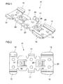
- Fig. 1 and Fig. 2 show in a perspective view a first mounting plate 11 of a door closer unit 1, which is formed according to the construction principle according to the invention.
- the mounting plate 11 has two holding portions 12 on both elongated sides of the mounting plate 11 for engagement with abutment portions 13 of the door operator 10 from a door closer unit 1, for example shown in FIG Fig. 3 ,
- the holding portions 12 have a wing-like construction.
- a projection 17 is provided between two adjacent ones Holding portions 12 on an elongated side of the mounting plate 11, a projection 17 is provided.
- the projection 17 is angled to the mounting plate 11, in particular angled at 90 ° to the mounting plate 11.
- Each projection 17 has a hole 20 for receiving a screw 21, in particular a countersunk screw on.
- the mounting plate 11 also has some holes 23 for receiving screws 24, see Fig. 5 for fixing the mounting plate 11 to a receptacle such as a door leaf, a lintel, a wall, a ceiling or the like.
- the mounting plate 11 has a flat or substantially planar extension.
- the mounting plate 11 has a stop element 50.
- the stop member 50 is adapted to abut against a counter-stop member 60 of the door operator 10 to allow the assembly movement of the door operator 10 at a defined position Fig. 3 , to stop.
- the hole 20 of each projection 17 is aligned with a hole 22 in the housing 15 of the door actuator 10, so that it is easily possible to screw fastening screws 21 through the holes 20, 22.
- the stopper 50 protrudes from the mounting plate 11.
- the stop element 50 allows in a simple manner the striking of a corresponding counter-stop element 60 of a door operator 10.
- the counter-stop element 60 protrudes on the inside of the door operator 10, in particular on the inside of the housing 15 of the door actuator 10, in the direction of the mounting plate 11, see Fig. 3 ,
- the stop member 50 comes into contact with the counter-stop member 60 of the door operator 10 to define a particular stop position of the door operator 10 relative to the mounting plate 11.
- the stopper member 50 of the mounting plate 11 has an end portion 52 disposed in parallel to the mounting plate 11, see Fig. 10 ,
- the stopper 50 is angled twice between the mounting plate 11 and the end position 52.
- the stop element 50 has a recess 51, in particular in the end section 52 of the stop element 50, for receiving the counterstop element 60, in particular a pin-shaped counterstop element 60, at the end of the assembly movement of the door actuator 10.
- the recess is funnel-shaped.
- the stop element 50 is designed such that at the end of the assembly movement, the counterstop element 60 slides into the recess 51 of the stop element 50. Therefore, door operator 10 can be aligned relative to the mounting plate 11.
- the stop member 50 ensures that the door operator 10 is guided to the correct position in which the holes 20, 22 are aligned to allow easy attachment of screws 21 to each other.
- the mounting plate 11 has a pin 25 which protrudes from the mounting plate 11.
- the pin 25 is designed for positive interaction with a guide element 30 of the door actuator 10, see Fig. 3 ,
- the pin 25 of the mounting plate 11, shown in FIG Fig. 1 and 2 Has a counter-guide element 26 in the form of a slot.
- the counter-guide member 26 serves to receive a guide member 30 of the door operator 10 in a positive manner.
- Such a pin 25 with a counter-guide member 30 ensures a defined guiding the door operator 10 during the mounting movement of the door operator 10 on the mounting plate eleventh
- Fig. 3 schematically shows in a view from below a door operator 10 of a door closer unit 1, which is designed according to the construction principle according to the invention.
- the counterstop member 60 for interacting with the stopper member 50 of the mounting plate 11 and the guide member 30 for interacting with the pin 25 of the mounting plate 11 are disposed on the inside of the door operator 10.
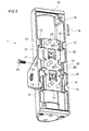
- Fig. 4 shows schematically in a view from below a door closer unit 1, which is designed according to the construction principle according to the invention.
- Fig. 5 shows schematically in a perspective view of the door closer unit 1 according to Fig. 4 ,
- the door operator 10 is arranged in the defined position in the mounting plate 11. That is, the mounting movement of the door operator 10 is stopped by the stopper 50 on the mounting plate 11.
- the counter-stop element 60 of the door operator 10, here in the form of a pin, is struck against the stop element 50 of the mounting plate 11. Further movement of the door actuator 10 along the mounting plate 11 is stopped and the defined position of the door operator 10 on the mounting plate 11 is reached.
- a door closer unit 1 allows a quick and easy and in particular accurate and secure mounting and securing the door operator 10 to the mounting plate 11 and thus a quick and easy and accurate and secure mounting and securing the door closer unit 1 to a receptacle such as a door leaf, a Lintel, a wall, a ceiling or something like that.
- the door closer unit 1 can be constructed in a material-saving manner. In particular, the door operator 10 does not need extra wings on the outside of the housing 15 to secure the door operator 10 to a receptacle.
- the door operator 10 recesses 70 for orthogonally receiving the holding portions 12 of the mounting plate 11, wherein the recesses 70 and the holding portions 12 are formed and tuned such that the door operator 10 only in a certain position relative to the mounting plate 11th can be placed on the mounting plate 11.
- the recesses 70 on each side within of the housing 15 are due to additionally added material 80 to the inner wall of the housing 15 where the hole 22 sits, different sizes.
- the recesses 70 and the holding portions 12 ensure that it is not possible to set the door operator 10 in the wrong way on the mounting plate 11. A user will not be able to mount the door actuator 10 to the mounting plate 11 if the orientation of the door operator 10 to the mounting plate 11 is incorrect.
- the recesses 70 within the housing 15 and the holding portions 12 of the mounting plate 11 are only compatible with each other when the door operator 10 has the correct orientation to the mounting plate 11.
- the door operator 10 has been placed over the mounting plate 11 perpendicular to the extension of the mounting plate 11. Subsequently, the door operator 10 is slipped along a mounting direction 14 on the mounting plate 11. During the slipping, the holding portions 12 of the mounting plate 11 and the counter-holding portions 13 of the housing 15 are at least partially engaged with each other in clamping engagement.
- screws 21 can be screwed into the holes 22 of the housing 15 and into the aligned holes 20 of the projections 17 of the mounting plate 11, see Fig. 5 , The stop member 50 and the counterstop member 60 allow the holes 20, 22 to be aligned with each other at the end of the assembly movement of the door operator 10 on the mounting plate 11.
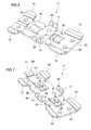
- Fig. 6 to 9 show in perspective views different mounting plates 11 of a door closer unit 1, which is formed according to the construction principle of the invention.
- mounting plate 11 has in addition to the stopper 50 on a resilient pin 25.
- the resilient pin 25 ensures that the door operator 10 at the end of the assembly movement held firmly to the mounting direction 14 on the mounting plate 11 can be.
- the resilient pin 25 protrudes from the mounting plate 11.
- mounting plate 11 has, in addition to the stopper 50, a first pin 25 and a second pin 35.
- the pins 25, 35 may be formed in a resilient manner.
- Each pin 25, 35 has counter-guide elements 26, 36.
- the counter-guide element 26, 36 has a slot for receiving the guide element 30 of the door operator 10 in a positive manner.
- the counter-guide member 26, 36 may also have a groove or a recess.
- Such pins 25, 35 with counter-guide elements 26, 36 ensure a defined guiding of the door actuator 10 during the mounting movement of the door operator 10 on the mounting plate 11.
- the stop element 50 having a recess 51, is arranged on a short side of the mounting plate 11.
- mounting plate 11 has in addition to the stopper 50, a pin 25 which is designed as an elongated pin on.
- the guide element 30 of the door operator 10 may have a guide rail for guiding the pin 25, in particular the elongated pin, on the mounting plate 11.
- a door closer unit 1 with such a mounting plate 11 ensures an improved alignment of the door actuator 10 on the mounting plate 11 and thus a simpler fastening of the screws 21 through the holes 20, 22 of the housing 15 of the door operator 10 and the projections 17 of the mounting plate 11.
- the door operator 10th can slide along the elongated pin 25 of the mounting plate 11. As a result of the defined sliding of the door actuator 10 on the mounting plate 11, a minimized movement between the door actuator 10 and the mounting plate 11 is ensured.
- mounting plate 11 has in addition to the stopper 50 has a pin 25 with an elongated slot 26 for receiving a guide member 30 of the door operator 10.
- a door closer unit 1 ensures improved alignment of the door operator 10 on the mounting plate 11 and thus easy attachment of the screws 21 through the holes 20, 22 of the housing 15 and the projections 17 on the mounting plate 11th
- Each of the mounting plates 11 of Fig. 6 to 9 has on the elongated sides an angled projection 17 with a hole 20 for receiving the fixing screw 21. At each elongated side, the projections 17 are arranged between two holding portions 12. The holding portions 12 on an elongated side of the mounting plate 11 are of different sizes, so that the door operator 10 can be placed on the mounting plate 11 only in a defined orientation.
Landscapes
- Hinges (AREA)
- Power-Operated Mechanisms For Wings (AREA)
Abstract
Die Erfindung bezieht sich auf eine Türschließereinheit (1) aufweisend einen Türbetätiger (10) mit einem Gehäuse (15) und aufweisend eine Montageplatte (11), wobei die Montageplatte (11) zur Montage des Türbetätigers (10) an einer Aufnahme wie einem Türblatt, einem Türsturz, einer Wand, einer Decke oder Dergleichen dient, wobei die Montageplatte (11) ein Stoppelement (50) aufweist und der Türbetätiger (10) ein Gegenstoppelement (60) aufweist, wobei das Stoppelement (50) zum Anschlagen des Gegenstoppelementes (60) ausgebildet ist, um die Montagebewegung des Türbetätigers (10) an einer definierten Position zu stoppen.
Description
- Die Erfindung betrifft eine Türschließereinheit aufweisend einen Türbetätiger mit einem Gehäuse und aufweisend eine Montageplatte, wobei die Montageplatte zur Montage des Türbetätigers an einer Aufnahme wie einem Türblatt, einem Türsturz, einer Wand, einer Decke oder Dergleichen dient. Das Gehäuse des Türbetätigers kann an der Montageplatte befestigt werden. Die Montageplatte weist zumindest zwei Halteabschnitte auf und das Gehäuse weist zumindest zwei Gegenhalteabschnitte auf, die den Halteabschnitten zugeordnet sind. Durch ein orthogonales Aufsetzen und ein seitliches Verschieben des Türbetätigers entlang einer Befestigungsrichtung auf der Montageplatte ist eine Montagebewegung des Türbetätigers definiert, bei der die Halteabschnitte mit den Gegenhalteabschnitten zumindest abschnittsweise miteinander in klemmenden Eingriff gelangen. Die Montageplatte der Türschließereinheit weist ferner zumindest einen Vorsprung mit einem Loch auf, wobei besagter zumindest einer Vorsprung um 90° oder im Wesentlichen 90° zu der Erstreckung der Montageplatte abgewinkelt ist. Das Gehäuse weist ferner zumindest ein Loch auf, wobei jedes Loch zur Aufnahme einer Schraube ausgebildet ist und jede Schraube zur Befestigung des Türbetätigers an der Montageplatte zum Ende der Montagebewegung geeignet ist.
- Türbetätiger können als mechanisch betätigbare Türbetätiger oder als elektrisch betätigbare Türantriebe ausgeführt sein. Ein mechanisch betätigbarer Türbetätiger weist einen Energiespeichermechanismus auf, wie einen federbasierten Speichermechanismus, in dem über eine manuell ausgeführte Öffnungsbewegung, beispielsweise eines Türblattes, potenzielle Energie gespeichert werden kann. Die gespeicherte Energie ist ausreichend, um anschließend eine Schließbewegung, z. B. des Türblattes, durchzuführen. Wenn der Türbetätiger ein elektrisch betätigbarer Türantrieb ist, kann der Türbetätiger beide Bewegungen ausführen, nämlich eine Öffnungs- und eine Schließbewegung, beispielsweise für ein Türblatt.
- Türbetätiger können direkt an einer Aufnahme, wie einem Türblatt, einem Türsturz, einer Wand, einer Decke oder Dergleichen montiert werden, indem zumindest zwei Schrauben verwendet werden, die durch den Türbetätiger hindurchgesteckt werden können und die anschließend in der Aufnahme verschraubt werden können. Ferner sind Türbetätiger, die derart ausgebildet sind, dass sie eine verbundene Tür, ein Fenster oder Dergleichen öffnen und/oder schließen können, typischerweise an einer Aufnahme, wie einem Türblatt, einem Türsturz, einer Wand, einer Decke oder Dergleichen mittels einer Montageplatte montiert. Dazu wird die Montageplatte beispielsweise zuerst an der Aufnahme, wie einem Türblatt, einem Türsturz, einer Wand, einer Decke oder Dergleichen montiert. Danach ist der entsprechende Türbetätiger an der Montageplatte befestigt. Das heißt, die Montageplatte hält den Türbetätiger an der Aufnahme. Wird eine Montageplatte verwendet, kann die Montageplatte an der Aufnahme beispielsweise durch Schrauben, insbesondere durch Holzschrauben oder Dübelschrauben, befestigt werden. Nachdem die Montageplatte an der Aufnahme befestigt ist, wird der Türbetätiger an der Montageplatte montiert. Es ist bekannt, den Türbetätiger an der Montageplatte durch Schrauben zu befestigen, die durch den Türbetätiger hindurchgeführt und senkrecht in die Montageplatte eingeschraubt werden. Ein Nachteil einer derartigen Befestigung ist, dass nach dem Montieren des Türbetätigers an der Montageplatte die Schraubenverbindung an der Oberseite des Türbetätigers sichtbar ist. Die Schrauben sind neben dem Griffbereich von hinten angeordnet. Daher können die Schraubenköpfe und die Öffnungen für die Schrauben einfach verschmutzen. Ferner kann eine Person ihre Hand verletzen aufgrund einer hervorstehenden Schraube. Folglich können Kappen verwendet werden zum Abdecken der Schraubenköpfe oder der Schraubenöffnungen. Aber derartige Kappen können einfach verlorengehen und können das Greifen einer Klinke der Türschließereinheit negativ beeinflussen.
- Ferner sind Türbetätiger bekannt, die Flansche außerhalb des Gehäuses des Türbetätigers aufweisen. Jeder Flansch hat ein Loch zum Durchführen einer Schraube, welche in die Tür oder den Türrahmen geschraubt wird. Ein Nachteil eines solchen Türbetätigers ist, dass extra Material erforderlich ist, um die Flansche zu bilden. Ein weiterer Nachteil ist, dass die Flansche den Körper des Türbetätigers vergrößern. Es ist ferner von Nachteil, dass die Schrauben von jedermann gesehen und einfach entfernt werden können.
- Es ist eine Aufgabe der Erfindung, eine Türschließereinheit gemäß dem Oberbegriff des Anspruchs 1 zu schaffen, die ein schnelles und einfaches und insbesondere ein exaktes und sicheres Montieren und Sichern des Türbetätigers an der Montageplatte und damit ein schnelles und einfaches und ein exaktes und sicheres Montieren und Sichern der Türschließereinheit an einer Aufnahme, wie einem Türblatt, einem Türsturz, einer Wand, einer Decke oder Dergleichen ermöglicht.
- Die zuvor erwähnte Aufgabe wird gelöst durch eine Türschließereinheit mit allen Merkmalen des unabhängigen Anspruchs 1. Vorteile, Merkmale, Details, Aspekte und Effekte der Erfindung ergeben sich aus den Unteransprüchen, der Beschreibung und den Figuren.
- Die zuvor erwähnte Aufgabe der Erfindung wird durch eine Türschließereinheit gelöst, aufweisend einen Türbetätiger mit einem Gehäuse und aufweisend eine Montageplatte, wobei die Montageplatte zur Montage des Türbetätigers an einer Aufnahme wie einem Türblatt, einem Türsturz, einer Wand, einer Decke oder Dergleichen dient, und wobei das Gehäuse des Türbetätigers an der Montageplatte befestigbar ist. Die Montageplatte weist zumindest zwei Paare von Halteabschnitten auf, und das Gehäuse weist zumindest zwei Paare von Gegenhalteabschnitten auf die den Halteabschnitten zugeordnet sind. Die Türschließereinheit ist ferner dadurch gekennzeichnet, dass durch ein orthogonales Aufsetzen und ein seitliches Verschieben des Türbetätigers entlang einer Befestigungsrichtung auf der Montageplatte eine Montagebewegung des Türbetätigers definiert ist, bei der die Halteabschnitte mit den Gegenhalteabschnitten zumindest abschnittsweise miteinander in klemmenden Eingriff gelangen. Die Montageplatte der Türschließereinheit weist zumindest einen Vorsprung mit einem Loch auf, wobei besagter zumindest einer Vorsprung 90° oder im Wesentlichen 90° zu der Erstreckung der Montageplatte abgewinkelt ist. Das Gehäuse der Türschließereinheit weist wenigstens ein Loch auf, wobei jedes Loch zur Aufnahme einer Schraube ausgebildet und jede Schraube zur Befestigung des Türbetätigers an der Montageplatte zum Ende der Montagebewegung geeignet ist.
- Die Türschließereinheit ist ferner dadurch gekennzeichnet, dass die Montageplatte ein Stoppelement aufweist und der Türbetätiger ein Gegenstoppelement aufweist, wobei das Stoppelement zum Anschlagen am Gegenstoppelement ausgebildet ist, um die Montagebewegung des Türbetätigers an einer definierten Position zu stoppen, wobei in der definierten Position das Loch jedes Vorsprungs mit einem Loch in dem Gehäuse fluchtend ausgerichtet ist.
- Eine derartige Türschließereinheit ermöglicht ein schnelles und einfaches und insbesondere exaktes und sicheres Montieren und Sichern des Türbetätigers an der Montageplatte und damit ein schnelles und einfaches und insbesondere ein exaktes und sicheres Montieren und Sichern der Türschließereinheit an einer Aufnahme, wie einem Türblatt, einem Türsturz, einer Wand, einer Decke oder Dergleichen. Die Türschließereinheit kann in einer materialsparenden Art ausgebildet werden. Insbesondere benötigt der Türbetätiger keine extra Flansche an der Außenseite des Gehäuses, um den Türbetätiger an einer Aufnahme zu befestigen.
- Die Halteabschnitte der Montageplatte sind vorteilhafterweise an beiden gegenüberliegenden länglichen Seiten der Montageplatte angeordnet. Es ist bevorzugt, dass an jeder länglichen Seite zwei Halteabschnitte angeordnet sind, die beabstandet voneinander sind. Die Halteabschnitte können eine flügelartige Konstruktion haben. Das Gehäuse, insbesondere das Innere des Gehäuses, weist vorteilhafterweise an beiden gegenüberliegenden länglichen Seiten Gegenhalteabschnitte auf, welche mit den entsprechenden Halteabschnitten der Montageplatte während der seitlichen Bewegung des Türbetätigers entlang der Befestigungsrichtung auf der Montageplatte eingreifen können. Es ist bevorzugt, dass an jeder länglichen Seite des Inneren des Gehäuses zwei Gegenhalteabschnitte, welche beabstandet voneinander sind, angeordnet sind.
- Der Türbetätiger kann über der Montageplatte platziert werden, insbesondere senkrecht zu der Erstreckung der Montageplatte. Danach kann der Türbetätiger entlang einer Befestigungsrichtung auf der Montageplatte verschoben werden. Während des Verschiebens gelangen die Halteabschnitte der Montageplatte und die Gegenhalteabschnitte des Gehäuses zumindest abschnittsweise miteinander in klemmenden Eingriff. Um den Türbetätiger an der Montageplatte zum Ende der Montagebewegung zu fixieren, ist es notwendig, dass das Loch des einen Vorsprungs mit einem Loch in dem Gehäuse des Türbetätigers fluchtend ausgerichtet ist. Wenn die Löcher nicht fluchtend ausgerichtet sind, ist es schwierig eine Schraube in den Löchern zu fixieren. Um dieses Problem zu überwinden, weist die Montageplatte der Türschließereinheit ein Stoppelement auf und der Türbetätiger weist ein Gegenstoppelement auf, wobei das Stoppelement zum Anschlagen am Gegenstoppelement ausgebildet ist, um die Montagebewegung des Türbetätigers an einer definierten Position zu stoppen. In der definierten Position ist das Loch jedes Vorsprungs mit einem Loch in dem Gehäuse fluchtend ausgerichtet. Das Stoppelement und das Gegenstoppelement ermöglichen, dass die Löcher am Ende der Montagebewegung des Türbetätigers an der Montageplatte fluchtend zueinander ausgerichtet sind, um die Schrauben zu befestigen.
- Der zumindest eine Vorsprung der Montageplatte ist um 90° oder im Wesentlichen um 90° abgewinkelt zu der Erstreckung der Montageplatte. Annähernd 90° abgewinkelt bedeutet, dass der Winkel zwischen der Erstreckung der Montageplatte und eines Vorsprungs zwischen 75° und 105° betragen kann. Bevorzugt ist eine Türschließereinheit mit einer Montageplatte, aufweisend zumindest einen Vorsprung, wobei der zumindest eine Vorsprung um 90° abgewinkelt zu der Montageplatte ist. Jeder Vorsprung weist ein Loch zur Aufnahme einer Schraube auf. Das Gehäuse weist zumindest ein Loch auf, jedes Loch zur Aufnahme einer Schraube, welche in ein Loch des Vorsprungs eingeschraubt werden kann, wenn die entsprechenden Löcher fluchtend zueinander ausgerichtet sind. Die Türschließereinheit weist zumindest eine Schraube, insbesondere eine Senkkopfschraube, auf, wobei jede Schraube zum Fixieren des Türbetätigers an der Montageplatte am Ende der Montagebewegung geeignet ist.
- Ein Vorteil des Stoppelementes und des Gegenstoppelementes ist, dass beide Elemente in einer sehr einfachen und kostensparenden Art konstruiert werden können. Das Stoppelement und das Gegenstoppelement sind zum Ineinandergreifen nicht in einer federelastischen Art ausgebildet. Wegen des Stoppelementes und des Gegenstoppelementes ist es möglich eine exakte Ausrichtung des Türbetätigers an der Montageplatte zum Einschrauben der Befestigungsschraube(n) zu realisieren. Das Ende der Montagebewegung ist erreicht, wenn das Stoppelement gegen das Gegenstoppelement anschlägt. Daher weiß eine Person, die den Türbetätiger an der Montageplatte verschiebt, wann die Montagebewegung beendet ist und das zumindest eine Loch des Gehäuses des Türbetätigers zu dem Loch in dem Vorsprung der Montageplatte fluchtend ausgerichtet ist. Durch Einschrauben von zumindest einer Schraube ist der Türbetätiger an der Montageplatte gesichert. Eine Entfernung des Türbetätigers von der Montageplatte in umgekehrter Richtung ist nach Entfernung der zumindest einen Fixierschraube möglich.
- Die Montageplatte hat eine ebene oder im Wesentlichen ebene Erstreckung. Daher kann die Montageplatte parallel zu einer Aufnahme wie einem Türblatt, einem Türsturz, einer Wand, einer Decke oder Dergleichen fixiert werden.
- Gemäß einer bevorzugten Weiterentwicklung der Erfindung kann eine Türschließereinheit vorgesehen sein, wobei das Stoppelement aus der Montageplatte heraussteht. Solch ein Stoppelement ermöglicht in einer einfachen Weise ein Anschlagen an ein entsprechendes Gegenstoppelement. Das Gegenstoppelement steht an der Innenseite des Türbetätigers, insbesondere an der Innenseite des Gehäuses, in Richtung zu der Montageplatte hervor. Ein Stoppelement, das aus der Erstreckung der Montageplatte hervorsteht, kann einfacher in Kontakt mit dem Gegenstoppelement des Türbetätigers gelangen.
- Eine Türschließereinheit ist bevorzugt, wobei das Stoppelement der Montageplatte einen Endabschnitt aufweist, der parallel zu der Montageplatte angeordnet ist. Das Stoppelement kann zweifach zwischen der Montageplatte und der Endposition abgewinkelt sein. Solch eine Endposition gewährleistet, dass das Stoppelement eine ausreichende Stabilität hat, wenn es gegen das Gegenstoppelement anschlägt.
- Gemäß einer weiteren bevorzugten Weiterentwicklung der Erfindung kann eine Türschließereinheit vorgesehen sein, welche dadurch gekennzeichnet ist, dass das Gegenstoppelement des Türbetätigers ein Vorsprung, insbesondere ein pinförmiger Vorsprung, innerhalb des Türbetätigers, insbesondere innerhalb des Gehäuses, ist. Das Gegenstoppelement ist in einer robusten Art an dem Türbetätiger befestigt, so dass es nicht brechen kann, wenn es am Ende der Montagebewegung durch das Stoppelement getroffen wird. Der Pin kann verschiedene Querschnitte aufweisen. Z. B. kann der Querschnitt des Pins mehrseitig, insbesondere rechteckig, sein. Bevorzugt ist ein Türbetätiger mit einem Pin mit einem kreisförmigen Querschnitt.
- Insbesondere ist eine Türschließereinheit bevorzugt, wobei das Stoppelement eine Aussparung zur Aufnahme des Gegenstoppelementes, insbesondere eines pinförmigen Gegenstoppelementes, zum Ende der Montagebewegung des Türbetätigers aufweist. Vorteilhafterweise ist die Aussparung trichterförmig ausgebildet. Das Stoppelement ist derart ausgebildet, dass am Ende der Montagebewegung das Gegenstoppelement in die Aussparung des Stoppelementes zum Ausrichten des Türbetätigers in der vordefinierten Position zu der Montageplatte gleitet. Solch ein Stoppelement gewährleistet, dass der Türbetätiger in die richtige Position geführt wird, in welcher die Löcher zum Ermöglichen von einer einfachen Befestigung der Schraube(n) fluchtend zueinander ausgerichtet sind. Insbesondere kann ein Gegenstoppelement mit einem kreisförmigen Querschnitt einfach in eine Aussparung des Stoppelementes hineingleiten, um eine definierte Stoppposition zu gewährleisten.
- Gemäß einer weiteren bevorzugten Weiterentwicklung der Erfindung kann eine Türschließereinheit vorgesehen sein, wobei zumindest ein Zapfen an der Montageplatte angeordnet ist, wobei der zumindest eine Zapfen aus der Montageplatte hervorsteht und wobei der Türbetätiger wenigstens ein Führungselement zum Ausrichten des Türbetätigers relativ zur Montageplatte während der Montagebewegung aufweist, wobei der zumindest eine Zapfen und das wenigstens eine Führungselement zum formschlüssigen Interagieren miteinander ausgebildet sind. Eine derartige Türschließereinheit ermöglicht in einer einfachen Weise, dass ein Nutzer nur fähig ist, den Türbetätiger in einer korrekten Art zu montieren. Der zumindest eine Zapfen minimiert die Bewegung zwischen dem Türbetätiger und der Montageplatte, insbesondere zum Ende der Montagebewegung. Ein bestimmtes Spiel zwischen den Halteabschnitten und den Gegenhalteabschnitten kann durch das zumindest eine Führungselement und den zumindest einen Zapfen kompensiert werden. Die Montageplatte kann zwei oder mehr Zapfen aufweisen. Zwei oder mehr Zapfen gewährleisten eine absolut richtige Ausrichtung des Türbetätigers zu der Montageplatte und damit eine korrekte Ausrichtung des zumindest einen Lochs des Gehäuses mit dem zumindest einen Loch in dem Vorsprung der Montageplatte.
- Es ist ferner bevorzugt, dass jeder Zapfen ein Gegenführungselement aufweist, insbesondere einen Schlitz, eine Nut oder eine Aussparung, zur formschlüssigen Aufnahme der Führungselemente des Türbetätigers. Ein Zapfen mit einem Gegenführungselement gewährleistet ein definiertes Führen des Türbetätigers während der Montagebewegung des Türbetätigers an der Montageplatte. Das Führungselement kann eine Führungsschiene und das Gegenführungselement kann einen Pin, insbesondere einen länglichen Pin, aufweisen oder das Gegenführungselement kann eine Führungsschiene und das Führungselement kann einen Pin, insbesondere einen länglichen Pin, aufweisen. Eine derartige Türschließereinheit gewährleistet eine verbesserte Ausrichtung des Türbetätigers an der Montageplatte und damit eine einfachere Befestigung der Schrauben durch die Löcher des Gehäuses und der Vorsprünge.
- Es ist ferner von Vorteil, dass das zumindest eine Führungselement des Türbetätigers eine Führungsschiene aufweist und das Gegenführungselement einen Pin, insbesondere einen länglichen Pin, aufweist oder dass das Gegenführungselement eine Führungsschiene aufweisen kann und das Führungselement einen Pin, insbesondere einen länglichen Pin, aufweisen kann. Eine derartige Türschließereinheit ermöglicht eine definierte Montagebewegung des Türbetätiger an der Montageplatte.
- Ferner ist eine Türschließereinheit bevorzugt, wobei der zumindest eine Zapfen federelastisch ausgebildet ist. Eine derartige Türschließereinheit ermöglicht, dass der Türbetätiger zusätzlich senkrecht zu der Befestigungsrichtung an der Montageplatte zum Ende der Montagebewegung ausgerichtet werden kann. Ferner stellt eine derartige Türschließereinheit sicher, dass das zumindest eine Führungselement des Türbetätigers sicher in formschlüssiger Art in das Gegenführungselement, insbesondere einen Schlitz, eine Nut oder eine Aussparung, geführt werden kann. Durch eine derartige Konstruktion des zumindest einen Zapfens der Montageplatte und derartige Führungselemente des Türbetätigers kann einfach gewährleistet werden, dass die Einführung des zumindest einen Zapfens in das Führungselement sehr gut vonstattengeht. Entweder das Führungselement oder das Gegenführungselement kann einen trichterförmiggen Eingang zum besseren Zuführen des entsprechenden Elementes aufweisen. Die Führungsschiene und das entsprechende Element sind, zumindest am Ende, derart ausgebildet, dass das Element formschlüssig in die Führungsschiene eingeführt werden kann. Eine derartige Führungsschiene minimiert die Bewegung zwischen dem Gehäuse und der Montageplatte.
- Gemäß einer besonders bevorzugten Weiterentwicklung der Erfindung kann eine Türschließereinheit vorgesehen sein, wobei innerhalb des Gehäuses Aussparungen zur orthogonalen Aufnahme der Halteabschnitte der Montageplatte angeordnet sind, wobei die Aussparungen und die Halteabschnitte derart ausgebildet und abgestimmt sind, dass der Türbetätiger nur in einer bestimmten Position relativ zur Montageplatte aufgesetzt werden kann. Dies stellt sicher, dass es nicht möglich ist, den Türbetätiger in falscher Weise auf die Montageplatte aufzusetzen. Das bedeutet, der Nutzer wird nicht fähig sein den Türbetätiger an der Montageplatte zu montieren, wenn die Orientierung des Türbetätigers falsch ist. Die Aussparungen innerhalb des Gehäuses und die Halteabschnitte der Montageplatte sind nur zueinander kompatibel, wenn der Türbetätiger die korrekte Orientierung zu der Montageplatte hat. Wegen der Aussparungen innerhalb des Gehäuses und den Halteabschnitten der Montageplatte kann ein Nutzer den Türbetätiger nur in einer einzigen Art auf die Montageplatte einführen, wenn die Orientierung beider Elemente korrekt ist.
- Daher ist es bevorzugt, dass die Aussparungen auf jeder Seite innerhalb des Gehäuses wegen des zusätzlichen Materials an der inneren Wand des Gehäuses des Türbetätigers, wo das Loch sitzt, unterschiedlich groß sind. Die Halteabschnitte müssen schmaler sein als die entsprechenden Aussparungen an der Innenseite des Gehäuses, so dass der Türbetätiger über die Halteabschnitte passt. Die Aussparungen können der Raum zwischen zwei benachbarten Vorsprüngen an der Innenseite des Gehäuses des Türbetätigers sein.
- Das Stoppelement und das Gegenstoppelement sowie der zumindest eine Zapfen der Montageplatte und die Führungselemente des Türbetätigers sind vorteilhafterweise einstückig, insbesondere monolithisch, mit dem entsprechenden Element, das bedeutet mit der Montageplatte oder dem Türbetätiger, angeordnet.
- Der zumindest eine Vorsprung der Montageplatte weist eine Gewindebohrung zur Aufnahme einer Schraube, die durch ein Loch des Gehäuses eingeschraubt werden kann, auf. Eine derartige Türschließereinheit ermöglicht ein absolut sicheres Fixieren des Türbetätigers an der Montageplatte. Nach dem Einschrauben der Schraube in die fluchtend ausgerichteten Löcher des Türbetätigers und des Vorsprungs/der Vorsprünge der Montageplatte, ist der Türbetätiger absolut sicher an der Montageplatte fixiert.
- Die Schraube kann eine Senkkopfschraube sein und vorteilhafterweise ist die Durchgangsbohrung des Gehäuses des Türbetätigers zur Aufnahme einer Senkkopfschraube ausgebildet. Das Loch in dem Gehäuse des Türbetätigers kann derart ausgebildet sein, dass es den Kopf einer Senkkopfschraube vollständig aufnehmen kann. Dies gewährleistet, dass die Schraube zum sicheren Fixieren des Türbetätigers an der Montageplatte nicht aus dem Gehäuse des Türbetätigers hervorsteht. Bevorzugt ist der Kopf der Senkkopfschraube plan mit der Außenseite des Gehäuses. Daher können Verletzungen und Verschmutzungen vermieden werden.
- Ferner ist eine Türschließereinheit bevorzugt, welche dadurch gekennzeichnet ist, dass die Montageplatte Löcher zur Aufnahme von Schrauben zur Fixierung der Montageplatte an einer Aufnahme, wie einem Türblatt, einem Türsturz, einer Wand, einer Decke oder Dergleichen, aufweist. Die Montageplatte kann durch Schrauben befestigt werden, welche durch Löcher in der Montageplatte in die Aufnahme geführt werden. Die Fixierung der Montageplatte an der Aufnahme muss erfolgen bevor der Türbetätiger an der Montageplatte montiert wird.
- Ein Vorteil einer zuvor beschriebenen Türschließereinheit ist, dass kein zusätzliches Loch in dem Gehäuse des Türbetätigers zum Einführen eines Werkzeuges zum Lösen des Türbetätigers von der Montageplatte erforderlich ist. Das Entfernen des Türbetätigers von der Montageplatte ist nach der Entfernung der Schrauben durch Verschieben des Türbetätigers in umgekehrte Richtung zu der Befestigungsrichtung möglich.
- Im Folgenden wird die vorliegende Erfindung durch Beispiele der Erfindung mit Bezug auf die beigefügten Figuren beschrieben, wobei:
- Fig. 1
- in einer perspektivischen Ansicht eine erste Montageplatte einer Türschließereinheit zeigt, welche gemäß dem erfindungsgemäßen Konstruktionsprinzip ausgebildet ist,
- Fig. 2
- in anderer perspektivischer Ansicht die erste Montageplatte gemäß
Fig. 1 zeigt, - Fig. 3
- in einer Ansicht von unten einen Türbetätiger einer Türschließereinheit zeigt, die gemäß dem erfindungsgemäßen Konstruktionsprinzip ausgebildet ist,
- Fig. 4
- in einer Ansicht von unten eine Türschließereinheit zeigt, welche gemäß dem erfindungsgemäßen Konstruktionsprinzip ausgebildet ist,
- Fig. 5
- in einer perspektivischen Ansicht die Türschließereinheit gemäß
Fig. 4 zeigt, - Fig. 6
- in einer perspektivischen Ansicht eine zweite Montageplatte einer Türschließereinheit zeigt, welche gemäß dem erfindungsgemäßen Konstruktionsprinzip ausgebildet ist,
- Fig. 7
- in einer perspektivischen Ansicht eine dritte Montageplatte einer Türschließereinheit zeigt, welche gemäß dem erfindungsgemäßen Konstruktionsprinzip ausgebildet ist,
- Fig. 8
- in einer perspektivischen Ansicht eine vierte Montageplatte einer Türschließereinheit zeigt, welche gemäß dem erfindungsgemäßen Konstruktionsprinzip ausgebildet ist,
- Fig. 9
- in einer perspektivischen Ansicht eine fünfte Montageplatte einer Türschließereinheit zeigt, welche gemäß dem erfindungsgemäßen Konstruktionsprinzip ausgebildet ist, und
- Fig, 10
- in einer perspektivischen Ansicht eine weitere Montageplatte einer Türschließereinheit zeigt, welche gemäß dem erfindungsgemäßen Konstruktionsprinzip ausgebildet ist.
- Elemente mit gleicher Funktion und Wirkweise sind in den
Fig. 1 bis 10 mit den gleichen Bezugszeichen versehen. -
Fig. 1 und Fig. 2 zeigen in einer perspektivischen Ansicht eine erste Montageplatte 11 einer Türschließereinheit 1, welche gemäß dem erfindungsgemäßen Konstruktionsprinzip ausgebildet ist. Die Montageplatte 11 weist zwei Halteabschnitte 12 an beiden länglichen Seiten der Montageplatte 11 auf zum Eingriff mit Gegenhalteabschnitten 13 des Türbetätigers 10 von einer Türschließereinheit 1, beispielsweise gezeigt inFig. 3 . Die Halteabschnitte 12 haben eine flügelähnliche Konstruktion. Zwischen zwei benachbarten Halteabschnitten 12 an einer länglichen Seite der Montageplatte 11 ist ein Vorsprung 17 vorgesehen. Der Vorsprung 17 ist abgewinkelt zu der Montageplatte 11, insbesondere um 90° zu der Montageplatte 11 abgewinkelt. Jeder Vorsprung 17 weist ein Loch 20 zur Aufnahme einer Schraube 21, insbesondere einer Senkkopfschraube, auf. Die Montageplatte 11 weist ferner einige Löcher 23 zur Aufnahme von Schrauben 24 auf, sieheFig. 5 , zum Fixieren der Montageplatte 11 an einer Aufnahme wie einem Türblatt, einem Türsturz, einer Wand, einer Decke oder Dergleichen. Die Montageplatte 11 hat eine ebene oder im Wesentlichen ebene Erstreckung. - Die Montageplatte 11 weist ein Stoppelement 50 auf. Das Stoppelement 50 ist ausgebildet zum Anschlagen an ein Gegenstoppelement 60 des Türbetätigers 10, um die Montagebewegung des Türbetätigers 10 an einer definierten Position, siehe
Fig. 3 , zu stoppen. In der definierten Position ist das Loch 20 jedes Vorsprungs 17 fluchtend ausgerichtet mit einem Loch 22 in dem Gehäuse 15 des Türbetätigers 10, so dass es einfach möglich ist Befestigungsschrauben 21 durch die Löcher 20, 22 zu schrauben. - Das Stoppelement 50 steht aus der Montageplatte 11 hervor. Das Stoppelement 50 ermöglicht in einfacher Art das Anschlagen an ein entsprechendes Gegenstoppelement 60 eines Türbetätigers 10. Das Gegenstoppelement 60 steht an der Innenseite des Türbetätigers 10, insbesondere an der Innenseite Gehäuses 15 des Türbetätigers 10, in Richtung zu der Montageplatte 11 hervor, siehe
Fig. 3 . Am Ende der Montagebewegung gerät das Stoppelement 50 in Kontakt mit dem Gegenstoppelement 60 des Türbetätigers 10, um eine bestimmte Stoppposition des Türbetätigers 10 relativ zu der Montageplatte 11 zu definieren. Das Stoppelement 50 der Montageplatte 11 weist einen Endabschnitt 52, der parallel zu der Montageplatte 11 angeordnet ist, auf, sieheFig. 10 . Das Stoppelement 50 ist zwischen der Montageplatte 11 und der Endposition 52 zweifach abgewinkelt. Eine derartige Endposition 52 gewährleistet, dass das Stoppelement 50 eine ausreichende Stabilität hat, wenn es gegen das Gegenstoppelement 60 anschlägt. Das Stoppelement 50 weist eine Aussparung 51, insbesondere in dem Endabschnitt 52 des Stoppelementes 50, auf zur Aufnahme des Gegenstoppelementes 60, insbesondere eines pinförmigen Gegenstoppelementes 60, am Ende der Montagebewegung des Türbetätigers 10 auf. Die Aussparung ist trichterförmig. Das Stoppelement 50 ist derart ausgebildet, dass am Ende der Montagebewegung das Gegenstoppelement 60 in die Aussparung 51 des Stoppelementes 50 hineingleitet. Daher kann Türbetätiger 10 relativ zu der Montageplatte 11 ausgerichtet werden. Das Stoppelement 50 gewährleistet, dass der Türbetätiger 10 in die richtige Position geführt wird, in welcher die Löcher 20, 22 zur Ermöglichung einer einfachen Befestigung von Schrauben 21 fluchtend zueinander ausgerichtet sind. - Ferner weist die Montageplatte 11 einen Zapfen 25 auf, welcher aus der Montageplatte 11 hervorsteht. Der Zapfen 25 ist zum formschlüssigen Interagieren mit einem Führungselement 30 des Türbetätigers 10 ausgebildet, siehe
Fig. 3 . - Der Zapfen 25 der Montageplatte 11, dargestellt in
Fig. 1 und 2 , weist ein Gegenführungselement 26 in Form eines Schlitzes auf. Das Gegenführungselement 26 dient zur Aufnahme eines Führungselementes 30 des Türbetätigers 10 in einer formschlüssigen Art. Ein derartiger Zapfen 25 mit einem Gegenführungselement 30 gewährleistet ein definiertes Führen des Türbetätigers 10 während der Montagebewegung des Türbetätigers 10 an der Montageplatte 11. -
Fig. 3 zeigt schematisch in einer Ansicht von unten einen Türbetätiger 10 einer Türschließereinheit 1, welche gemäß dem erfindungsgemäßen Konstruktionsprinzip ausgebildet ist. Das Gegenstoppelement 60 zum Interagieren mit dem Stoppelement 50 der Montageplatte 11 und das Führungselement 30 zum Interagieren mit dem Zapfen 25 der Montageplatte 11 sind an der Innenseite des Türbetätigers 10 angeordnet. -
Fig. 4 zeigt schematisch in einer Ansicht von unten eine Türschließereinheit 1, welche gemäß dem erfindungsgemäßen Konstruktionsprinzip ausgebildet ist.Fig. 5 zeigt schematisch in einer perspektivischen Ansicht die Türschließereinheit 1 gemäßFig. 4 . Der Türbetätiger 10 ist in der definierten Position in der Montageplatte 11 angeordnet. Das bedeutet, die Montagebewegung des Türbetätigers 10 ist durch das Stoppelement 50 auf der Montageplatte 11 gestoppt. Das Gegenstoppelement 60 des Türbetätigers 10, hier in Form eines Pins, ist gegen das Stoppelement 50 der Montageplatte 11 angeschlagen. Eine weitere Bewegung des Türbetätigers 10 entlang der Montageplatte 11 ist gestoppt und die definierte Position des Türbetätigers 10 an der Montageplatte 11 ist erreicht. In der definierten Position ist das Loch 20 jedes Vorsprungs 17 auf der Montageplatte 11 mit einem Loch 22 in dem Gehäuse 15 des Türbetätigers 10 fluchtend ausgerichtet. Das Führungselement 30 des Türbetätigers 10 ist in das Gegenführungselement 26 des Zapfens 25 an der Montageplatte 11 in formschlüssiger Art hineingeglitten. Damit ist die Bewegung zwischen dem Gehäuse 15 des Türbetätigers 10 und der Montageplatte 11 minimiert. Eine derartige Türschließereinheit 1 ermöglicht ein schnelles und einfaches und insbesondere ein exaktes und sicheres Montieren und Sichern des Türbetätigers 10 an der Montageplatte 11 und damit ein schnelles und einfaches und ein exaktes und sicheres Montieren und Sichern der Türschließereinheit 1 an einer Aufnahme wie einem Türblatt, einem Türsturz, einer Wand, einer Decke oder Dergleichen. Die Türschließereinheit 1 kann in einer materialsparenden Art gebaut sein. Insbesondere braucht der Türbetätiger 10 keine extra Flügel an der Außenseite des Gehäuses 15, um den Türbetätiger 10 an einer Aufnahme zu befestigen. - An der Innenseite des Gehäuses 15 weist der Türbetätiger 10 Aussparungen 70 zur orthogonalen Aufnahme der Halteabschnitte 12 der Montageplatte 11 auf, wobei die Aussparungen 70 und die Halteabschnitte 12 derart ausgebildet und abgestimmt sind, dass der Türbetätiger 10 nur in einer bestimmten Position relativ zur Montageplatte 11 an der Montageplatte 11 aufgesetzt werden kann. Die Aussparungen 70 an jeder Seite innerhalb des Gehäuses 15 sind wegen zusätzlich hinzugefügten Materials 80 an die innere Wand des Gehäuses 15, wo das Loch 22 sitzt, unterschiedlich groß. Die Aussparungen 70 und die Halteabschnitte 12 gewährleisten, dass es nicht möglich ist, den Türbetätiger 10 in falscher Art auf die Montageplatte 11 aufzusetzen. Ein Nutzer wird nicht fähig sein, den Türbetätiger 10 an die Montageplatte 11 zu montieren, wenn die Orientierung des Türbetätigers 10 zu der Montageplatte 11 falsch ist. Die Aussparungen 70 innerhalb des Gehäuses 15 und die Halteabschnitte 12 der Montageplatte 11 sind nur kompatibel zueinander, wenn der Türbetätiger 10 die richtige Orientierung zu der Montageplatte 11 hat.
- Der Türbetätiger 10 ist über die Montageplatte 11 senkrecht zu der Erstreckung der Montageplatte 11 platziert worden. Anschließend ist der Türbetätiger 10 entlang einer Befestigungsrichtung 14 an der Montageplatte 11 aufgeglitten. Während des Aufgleitens sind die Halteabschnitte 12 der Montageplatte 11 und die Gegenhalteabschnitte 13 des Gehäuses 15 zumindest abschnittsweise miteinander in klemmenden Eingriff gelangt. Um den Türbetätiger 10 an der Montageplatte 11 zu fixieren, können Schrauben 21 in die Löcher 22 des Gehäuses 15 und in die fluchtend ausgerichteten Löcher 20 der Vorsprünge 17 der Montageplatte 11 eingeschraubt werden, siehe
Fig. 5 . Das Stoppelement 50 und das Gegenstoppelement 60 ermöglichen, dass die Löcher 20, 22 am Ende der Montagebewegung des Türbetätigers 10 an der Montageplatte 11 fluchtend zueinander ausgerichtet sind. -
Fig. 6 bis 9 zeigen in perspektivischen Ansichten verschiedene Montageplatten 11 einer Türschließereinheit 1, welche gemäß dem erfindungsgemäßen Konstruktionsprinzip ausgebildet ist. - Die in
Fig. 6 gezeigte Montageplatte 11 weist zusätzlich zu dem Stoppelement 50 einen federelastischen Zapfen 25 auf. Der federelastische Zapfen 25 gewährleistet, dass der Türbetätiger 10 am Ende der Montagebewegung fest zu der Montagerichtung 14 auf der Montageplatte 11 gehalten werden kann. Der federelastische Zapfen 25 steht aus der Montageplatte 11 hervor. - Die in
Fig. 7 gezeigte Montageplatte 11 weist zusätzlich zu dem Stoppelement 50 einen ersten Zapfen 25 und einen zweiten Zapfen 35 auf. Die Zapfen 25, 35 können in einer federelastischen Art ausgebildet sein. Jeder Zapfen 25, 35 weist Gegenführungselemente 26, 36 auf. Das Gegenführungselement 26, 36 weist einen Schlitz zur Aufnahme des Führungselementes 30 des Türbetätigers 10 in formschlüssiger Art auf. Das Gegenführungselement 26, 36 kann auch eine Nut oder eine Aussparung aufweisen. Derartige Zapfen 25, 35 mit Gegenführungselementen 26, 36 gewährleisten ein definiertes Führen des Türbetätigers 10 während der Montagebewegung des Türbetätigers 10 an der Montageplatte 11. Das Stoppelement 50, aufweisend eine Aussparung 51, ist an einer kurzen Seite der Montageplatte 11 angeordnet. - Die in
Fig. 8 gezeigte Montageplatte 11 weist zusätzlich zu dem Stoppelement 50 einen Zapfen 25, welcher als länglicher Pin ausgestaltet ist, auf. Das Führungselement 30 des Türbetätigers 10 kann eine Führungsschiene zum Führen des Zapfens 25, insbesondere des länglichen Pins, an der Montageplatte 11 aufweisen. Eine Türschließereinheit 1 mit einer derartigen Montageplatte 11 gewährleistet ein verbessertes Ausrichten des Türbetätigers 10 an der Montageplatte 11 und damit eine einfachere Befestigung der Schrauben 21 durch die Löcher 20, 22 des Gehäuses 15 des Türbetätigers 10 und der Vorsprünge 17 der Montageplatte 11. Der Türbetätiger 10 kann entlang des länglichen Pins 25 der Montageplatte 11 gleiten. Als Ergebnis des definierten Gleitens des Türbetätigers 10 an der Montageplatte 11 ist eine minimierte Bewegung zwischen dem Türbetätiger 10 und der Montageplatte 11 sichergestellt. - Die in
Fig. 9 gezeigte Montageplatte 11 weist zusätzlich zu dem Stoppelement 50 einen Zapfen 25 mit einem länglichen Schlitz 26 zur Aufnahme eines Führungselementes 30 des Türbetätigers 10 auf. Eine derartige Montageplatte 11 einer Türschließereinheit 1 gewährleistet eine verbesserte Ausrichtung des Türbetätigers 10 an der Montageplatte 11 und damit eine einfache Befestigung der Schrauben 21 durch die Löcher 20, 22 des Gehäuses 15 und der Vorsprünge 17 an der Montageplatte 11. - Jede der Montageplatten 11 der
Fig. 6 bis 9 weist an den länglichen Seiten einen abgewinkelten Vorsprung 17 mit einem Loch 20 auf zur Aufnahme der Befestigungsschraube 21. An jeder länglichen Seite sind die Vorsprünge 17 zwischen zwei Halteabschnitten 12 angeordnet. Die Halteabschnitte 12 an einer länglichen Seite der Montageplatte 11 sind von unterschiedlicher Größe, so dass der Türbetätiger 10 auf die Montageplatte 11 nur in einer definierten Orientierung aufgesetzt werden kann. - Nach dem Erreichen der definierten Position an der Montageplatte 11 durch Anschlagen an dem Stoppelement 50 der Montageplatte 11, können Schrauben 21 einfach durch die Löcher 22 des Gehäuses 15 in fluchtend ausgerichtete Löcher 20 der Vorsprünge 17 der Montageplatte 11 eingeschraubt werden.
Bezugszeichenliste 1 Türschließereinheit 10 Türbetätiger 11 Montageplatte 12 Halteabschnitte 13 Gegenhalteabschnitte 14 Befestigungsrichtung 15 Gehäuse des Türbetätigers 17 Plattenvorsprung 20 Loch im Plattenvorsprung 21 Schraube 22 Loch im Gehäuse 23 Löcher in der Montageplatte 24 Schrauben der Montageplatte 25 (erster) Zapfen 26 Gegenführungselement (Schlitz) im (ersten) Zapfen 30 Führungselement 35 zweiter Zapfen 36 Gegenführungselement (Schlitz) im (zweiten) Zapfen 50 Stoppelement 51 Aussparung im Stoppelement 60 Gegenstoppelement 70 Aussparung innerhalb des Gehäuses 80 zusätzliches Material an inneren Seite
Claims (15)
- Türschließereinheit (1) aufweisend einen Türbetätiger (10) mit einem Gehäuse (15) und aufweisend eine Montageplatte (11), wobei die Montageplatte (11) zur Montage des Türbetätigers (10) an einer Aufnahme wie einem Türblatt, einem Türsturz, einer Wand, einer Decke oder Dergleichen dient, wobei der Türbetätiger (10) an der Montageplatte (11) befestigbar ist, wobei das Gehäuse (15) des Türbetätigers (10) an der Montageplatte (11) befestigbar ist, wobei die Montageplatte (11) zumindest zwei Paare von Halteabschnitten (12) aufweist und das Gehäuse (15) zumindest zwei Paare von Gegenhalteabschnitten (13), die den Halteabschnitten (12) zugeordnet sind, aufweist, wobei durch ein orthogonales Aufsetzen und ein seitliches Verschieben des Türbetätigers (10) entlang einer Befestigungsrichtung (14) auf der Montageplatte (11) eine Montagebewegung definiert ist, bei der die Halteabschnitte (12) mit den Gegenhalteabschnitten (13) zumindest abschnittsweise miteinander in klemmenden Eingriff gelangen, wobei die Montageplatte (11) zumindest einen Vorsprung (17) mit einem Loch (20) aufweist, wobei der zumindest eine Vorsprung (17) um 90° oder im Wesentlichen um 90° zu der Erstreckung der Montageplatte (11) abgewinkeit ist, wobei das Gehäuse (15) wenigstens ein Loch (22) aufweist, wobei jedes Loch zur Aufnahme einer Schraube (21) ausgebildet und jede Schraube (21) zur Befestigung des Türbetätigers (10) an der Montageplatte (11) zum Ende der Montagebewegung geeignet ist, dadurch gekennzeichnet, dass die Montageplatte (11) ein Stoppelement (50) aufweist und der Türbetätiger (10) ein Gegenstoppelement (60) aufweist, wobei das Stoppelement (50) zum Anschlagen des Gegenstoppelementes (60) ausgebildet ist, um die Montagebewegung des Türbetätigers (10) an einer definierten Position zu stoppen, wobei in der definierten Position das Loch (20) jedes Vorsprunges (17) mit einem Loch (22) in dem Gehäuse (15) fluchtend ausgerichtet ist.
- Türschließereinheit (1) gemäß Anspruch 1, dadurch gekennzeichnet, dass das Stoppelement (50) aus der Montageplatte (11) hervorsteht.
- Türschließereinheit (1) gemäß Anspruch 1 oder 2, dadurch gekennzeichnet, dass das Stoppelement (50) einen Endabschnitt (52) aufweist, der parallel zu der Montageplatte (11) angeordnet ist.
- Türschließereinheit (1) gemäß Anspruch 3, dadurch gekennzeichnet, dass das Stoppelement (50) zwischen der Montageplatte (11) und dem Endabschnitt (52) zweifach abgewinkelt (53, 54) ist.
- Türschließereinheit (1) gemäß wenigstens einem der vorhergehenden Ansprüche, dadurch gekennzeichnet, dass das Gegenstoppelement (60) ein Vorsprung, insbesondere ein pinförmiger Vorsprung, innerhalb des Türbetätigers (10), insbesondere innerhalb des Gehäuses (15), ist.
- Türschließereinheit (1) gemäß wenigstens einem der vorhergehenden Ansprüche, dadurch gekennzeichnet, dass das Stoppelement (50) eine Aussparung (51) zur Aufnahme des Gegenstoppelementes (60) am Ende der Montagebewegung des Türbetätigers (10) aufweist.
- Türschließereinheit (1) gemäß Anspruch 6, dadurch gekennzeichnet, dass die Aussparung (51) trichterförmig ausgebildet ist.
- Türschließereinheit (1) gemäß wenigstens einem der vorhergehenden Ansprüche, dadurch gekennzeichnet, dass zumindest ein Zapfen (25, 35) an der Montageplatte (11) angeordnet ist, wobei der zumindest eine Zapfen (25, 35) aus der Montageplatte (11) hervorsteht, und dass der Türbetätiger (10) wenigstens ein Führungselement (30) zum Ausrichten des Türbetätigers (10) relativ zur Montageplatte (11) während der Montagebewegung aufweist, wobei der zumindest eine Zapfen (25, 35) und das wenigstens eine Führungselement 30) zum formschlüssigen Interagieren miteinander ausgebildet sind.
- Türschließereinheit (1) gemäß Anspruch 8, dadurch gekennzeichnet, dass jeder Zapfen (25, 35) Gegenführungselemente (26, 36), insbesondere einen Schlitz, eine Nut oder eine Aussparung, zur formschlüssigen Aufnahme des Führungselementes (30) des Türbetätigers (10) aufweist.
- Türschließereinheit (1) gemäß Anspruch 9, dadurch gekennzeichnet, dass das wenigstens eine Führungselement (30) eine Führungsschiene und die Gegenführungselemente (26, 36) einen Pin, insbesondere einen länglichen Pin, oder die Gegenführungselemente (26, 36) eine Führungsschiene und das Führungselement (30) einen Pin, insbesondere einen länglichen Pin, aufweisen.
- Türschließereinheit (1) gemäß wenigstens einem der vorhergehenden Ansprüche 8 bis 10, dadurch gekennzeichnet, dass der zumindest eine Zapfen (25, 35) federelastisch ausgebildet ist.
- Türschließereinheit (1) gemäß wenigstens einem der vorhergehenden Ansprüche 9 bis 11, dadurch gekennzeichnet, dass das Gegenführungselement (26) einen trichterförmigen Eingang aufweist.
- Türschließereinheit (1) gemäß wenigstens einem der vorhergehenden Ansprüche, dadurch gekennzeichnet, dass innerhalb des Gehäuses Aussparungen (70) zur orthogonalen Aufnahme der Halteabschnitte (12) der Montageplatte (11) angeordnet sind, wobei die Aussparungen (70) und die Halteabschnitts (12) derart ausgebildet und abgestimmt sind, dass der Türbetätiger (10) nur in einer bestimmten Position relativ zur Montageplatte (11) an der Montageplatte (11) aufgesetzt werden kann.
- Türschließereinheit (1) gemäß wenigstens einem der vorhergehenden Ansprüche, dadurch gekennzeichnet, dass die Aussparungen (70) an jeder Seite innerhalb des Gehäuses (15) wegen des zusätzlichen Materials (80) an der inneren Wand, wo das Loch (22) sitzt, unterschiedlich groß sind.
- Türschließereinheit (1) gemäß wenigstens einem der vorhergehenden Ansprüche, dadurch gekennzeichnet, dass das zumindest eine Loch (22) in dem Gehäuse (15) zur Aufnahme einer Senkkopfschraube (21) ausgebildet ist.
Applications Claiming Priority (1)
| Application Number | Priority Date | Filing Date | Title |
|---|---|---|---|
| DE102012105118A DE102012105118A1 (de) | 2012-06-13 | 2012-06-13 | Türschließereinheit |
Publications (1)
| Publication Number | Publication Date |
|---|---|
| EP2674556A2 true EP2674556A2 (de) | 2013-12-18 |
Family
ID=48190046
Family Applications (1)
| Application Number | Title | Priority Date | Filing Date |
|---|---|---|---|
| EP13002128.0A Withdrawn EP2674556A2 (de) | 2012-06-13 | 2013-04-23 | Türschließereinheit |
Country Status (3)
| Country | Link |
|---|---|
| EP (1) | EP2674556A2 (de) |
| CN (1) | CN103485639A (de) |
| DE (1) | DE102012105118A1 (de) |
Cited By (1)
| Publication number | Priority date | Publication date | Assignee | Title |
|---|---|---|---|---|
| DE102014222886A1 (de) * | 2014-11-10 | 2016-05-12 | Geze Gmbh | System zur Befestigung eines obenliegenden Türschließers |
-
2012
- 2012-06-13 DE DE102012105118A patent/DE102012105118A1/de not_active Withdrawn
-
2013
- 2013-04-23 EP EP13002128.0A patent/EP2674556A2/de not_active Withdrawn
- 2013-06-13 CN CN201310233578.7A patent/CN103485639A/zh active Pending
Non-Patent Citations (1)
| Title |
|---|
| None |
Cited By (2)
| Publication number | Priority date | Publication date | Assignee | Title |
|---|---|---|---|---|
| DE102014222886A1 (de) * | 2014-11-10 | 2016-05-12 | Geze Gmbh | System zur Befestigung eines obenliegenden Türschließers |
| DE102014222886B4 (de) | 2014-11-10 | 2024-02-15 | Geze Gmbh | System zur Befestigung eines obenliegenden Türschließers |
Also Published As
| Publication number | Publication date |
|---|---|
| CN103485639A (zh) | 2014-01-01 |
| DE102012105118A1 (de) | 2013-12-19 |
Similar Documents
| Publication | Publication Date | Title |
|---|---|---|
| DE102018006297B4 (de) | Mehrteiliger Clip zum Befestigen eines Elementes an einem anderen Element | |
| DE202017100971U1 (de) | Montagevorrichtung zum Einsetzen von Rahmenelementen in Wandöffnungen | |
| EP0894175A2 (de) | Für eine rastmontage eingerichteter stangenverschluss | |
| EP3486420A2 (de) | Vorrichtung zum positionieren eines fensters oder einer tür | |
| EP3535824B1 (de) | Sammelschienenhalter und eine entsprechende anordnung | |
| DE102010023689A1 (de) | Montageanordnung für einen Türbetätiger | |
| DE69805903T2 (de) | Beschlag mit einstellbarem Riegel für Schiebeflügel | |
| WO2013068083A1 (de) | Türschliessereinheit | |
| WO2012130359A1 (de) | Türschliessersystem | |
| EP3219891A1 (de) | Dreidimensional verstellbares bandsystem | |
| WO2020126130A1 (de) | Schloss mit treibriegelanordnung, montagekappe und verfahren zum justieren einer treibriegelstange | |
| DE102012105118A1 (de) | Türschließereinheit | |
| EP2669457A1 (de) | Türschließereinheit und Verfahren zum Montieren eines Türbetätigers an einer Montageplatte einer Türschließereinheit | |
| EP2863000B1 (de) | Aufschiebesicherungsanordnung | |
| DE3151668A1 (de) | "kupplungsvorrichtung fuer eine fotografische blitzeinrichtung" | |
| DE202021100558U1 (de) | Verriegelungseinrichtung für ein Betätigungshandhabenpaar einer Tür | |
| DE69510412T2 (de) | Verschluss für Schiebefenster oder Schiebetür mit falscher Handhabung Vorbeugen der Vorrichtung | |
| DE102016103520B3 (de) | Türzargenanordnung sowie Distanzstück für eine Türzargenanordnung | |
| EP2167764B1 (de) | Montagehilfsvorrichtung für ein einsteckschloss sowie einsteckschloss | |
| WO2012139697A1 (de) | Türschliessersystem | |
| EP2532816B1 (de) | Antriebsvorrichtung für einen Treibstangenbeschlag | |
| EP2655770A1 (de) | Montageanordnung für einen türbetätiger zur verbindungsmittellosen montage auf einer montageplatte | |
| DE202004001861U1 (de) | Schließvorrichtung | |
| EP1574726A1 (de) | Holzbauverbindung, insbesondere für Fertighäuser | |
| DE202021103199U1 (de) | Türöffnerbaugruppe |
Legal Events
| Date | Code | Title | Description |
|---|---|---|---|
| PUAI | Public reference made under article 153(3) epc to a published international application that has entered the european phase |
Free format text: ORIGINAL CODE: 0009012 |
|
| AK | Designated contracting states |
Kind code of ref document: A2 Designated state(s): AL AT BE BG CH CY CZ DE DK EE ES FI FR GB GR HR HU IE IS IT LI LT LU LV MC MK MT NL NO PL PT RO RS SE SI SK SM TR |
|
| AX | Request for extension of the european patent |
Extension state: BA ME |
|
| RAP1 | Party data changed (applicant data changed or rights of an application transferred) |
Owner name: DORMA DEUTSCHLAND GMBH |
|
| STAA | Information on the status of an ep patent application or granted ep patent |
Free format text: STATUS: THE APPLICATION HAS BEEN WITHDRAWN |
|
| 18W | Application withdrawn |
Effective date: 20150505 |