EP2674479A1 - Bioréacteur jetable et plaque frontale, ainsi que procédés de fabrication - Google Patents
Bioréacteur jetable et plaque frontale, ainsi que procédés de fabrication Download PDFInfo
- Publication number
- EP2674479A1 EP2674479A1 EP12172304.3A EP12172304A EP2674479A1 EP 2674479 A1 EP2674479 A1 EP 2674479A1 EP 12172304 A EP12172304 A EP 12172304A EP 2674479 A1 EP2674479 A1 EP 2674479A1
- Authority
- EP
- European Patent Office
- Prior art keywords
- head plate
- disposable bioreactor
- top plate
- bioreactor
- magnetic
- Prior art date
- Legal status (The legal status is an assumption and is not a legal conclusion. Google has not performed a legal analysis and makes no representation as to the accuracy of the status listed.)
- Granted
Links
- 238000004519 manufacturing process Methods 0.000 title claims abstract description 25
- 238000003756 stirring Methods 0.000 claims abstract description 57
- 238000006243 chemical reaction Methods 0.000 claims abstract description 54
- 239000000463 material Substances 0.000 claims description 57
- 238000004113 cell culture Methods 0.000 claims description 21
- 230000008878 coupling Effects 0.000 claims description 17
- 238000010168 coupling process Methods 0.000 claims description 17
- 238000005859 coupling reaction Methods 0.000 claims description 17
- 239000002131 composite material Substances 0.000 claims description 16
- 238000003466 welding Methods 0.000 claims description 16
- 238000001746 injection moulding Methods 0.000 claims description 12
- 239000004033 plastic Substances 0.000 claims description 8
- 229920003023 plastic Polymers 0.000 claims description 8
- 239000000696 magnetic material Substances 0.000 claims description 7
- 229920000642 polymer Polymers 0.000 claims description 7
- 239000011159 matrix material Substances 0.000 claims description 6
- 238000005096 rolling process Methods 0.000 claims description 6
- 239000011521 glass Substances 0.000 claims description 4
- 238000004026 adhesive bonding Methods 0.000 claims description 3
- 239000011324 bead Substances 0.000 claims description 3
- 239000012815 thermoplastic material Substances 0.000 claims description 2
- 238000000034 method Methods 0.000 abstract description 25
- 230000008901 benefit Effects 0.000 description 28
- 238000013461 design Methods 0.000 description 15
- 230000008569 process Effects 0.000 description 15
- 239000007789 gas Substances 0.000 description 14
- 238000005202 decontamination Methods 0.000 description 10
- -1 polyethylene Polymers 0.000 description 10
- 230000001954 sterilising effect Effects 0.000 description 10
- 238000004659 sterilization and disinfection Methods 0.000 description 10
- 239000004952 Polyamide Substances 0.000 description 8
- 230000009477 glass transition Effects 0.000 description 8
- 229920002647 polyamide Polymers 0.000 description 8
- 239000004743 Polypropylene Substances 0.000 description 6
- 230000003588 decontaminative effect Effects 0.000 description 6
- 229920001155 polypropylene Polymers 0.000 description 6
- 239000004793 Polystyrene Substances 0.000 description 5
- 210000004027 cell Anatomy 0.000 description 5
- 230000000694 effects Effects 0.000 description 5
- 239000012530 fluid Substances 0.000 description 5
- 239000004417 polycarbonate Substances 0.000 description 5
- 229920000515 polycarbonate Polymers 0.000 description 5
- 229920002223 polystyrene Polymers 0.000 description 5
- 238000005507 spraying Methods 0.000 description 5
- 238000003860 storage Methods 0.000 description 5
- 239000000126 substance Substances 0.000 description 5
- 238000012549 training Methods 0.000 description 5
- 230000015572 biosynthetic process Effects 0.000 description 4
- 238000001816 cooling Methods 0.000 description 4
- 238000013400 design of experiment Methods 0.000 description 4
- 238000011161 development Methods 0.000 description 4
- 230000018109 developmental process Effects 0.000 description 4
- 238000002156 mixing Methods 0.000 description 4
- 229920000306 polymethylpentene Polymers 0.000 description 4
- 239000011116 polymethylpentene Substances 0.000 description 4
- 238000011165 process development Methods 0.000 description 4
- 238000007789 sealing Methods 0.000 description 4
- 238000011109 contamination Methods 0.000 description 3
- 239000007788 liquid Substances 0.000 description 3
- 230000002906 microbiologic effect Effects 0.000 description 3
- 229920002959 polymer blend Polymers 0.000 description 3
- 238000012827 research and development Methods 0.000 description 3
- 238000005496 tempering Methods 0.000 description 3
- 239000002033 PVDF binder Substances 0.000 description 2
- 239000004696 Poly ether ether ketone Substances 0.000 description 2
- 239000004698 Polyethylene Substances 0.000 description 2
- 230000009471 action Effects 0.000 description 2
- 230000002411 adverse Effects 0.000 description 2
- QVGXLLKOCUKJST-UHFFFAOYSA-N atomic oxygen Chemical compound [O] QVGXLLKOCUKJST-UHFFFAOYSA-N 0.000 description 2
- 238000011138 biotechnological process Methods 0.000 description 2
- 230000008859 change Effects 0.000 description 2
- 238000004140 cleaning Methods 0.000 description 2
- 238000005520 cutting process Methods 0.000 description 2
- 238000002347 injection Methods 0.000 description 2
- 239000007924 injection Substances 0.000 description 2
- 230000010354 integration Effects 0.000 description 2
- 238000005304 joining Methods 0.000 description 2
- 244000005700 microbiome Species 0.000 description 2
- 229910052760 oxygen Inorganic materials 0.000 description 2
- 239000001301 oxygen Substances 0.000 description 2
- 229920002530 polyetherether ketone Polymers 0.000 description 2
- 229920000573 polyethylene Polymers 0.000 description 2
- 229920001343 polytetrafluoroethylene Polymers 0.000 description 2
- 239000004810 polytetrafluoroethylene Substances 0.000 description 2
- 229920002981 polyvinylidene fluoride Polymers 0.000 description 2
- 238000005070 sampling Methods 0.000 description 2
- 241000894006 Bacteria Species 0.000 description 1
- 241000699802 Cricetulus griseus Species 0.000 description 1
- 241000233866 Fungi Species 0.000 description 1
- 241001465754 Metazoa Species 0.000 description 1
- 240000004808 Saccharomyces cerevisiae Species 0.000 description 1
- 238000005299 abrasion Methods 0.000 description 1
- 238000005054 agglomeration Methods 0.000 description 1
- 230000002776 aggregation Effects 0.000 description 1
- QXJJQWWVWRCVQT-UHFFFAOYSA-K calcium;sodium;phosphate Chemical compound [Na+].[Ca+2].[O-]P([O-])([O-])=O QXJJQWWVWRCVQT-UHFFFAOYSA-K 0.000 description 1
- 150000001875 compounds Chemical class 0.000 description 1
- 238000010276 construction Methods 0.000 description 1
- 238000002474 experimental method Methods 0.000 description 1
- 230000005484 gravity Effects 0.000 description 1
- 210000004408 hybridoma Anatomy 0.000 description 1
- 238000007654 immersion Methods 0.000 description 1
- 230000036512 infertility Effects 0.000 description 1
- 238000002844 melting Methods 0.000 description 1
- 230000008018 melting Effects 0.000 description 1
- 239000012528 membrane Substances 0.000 description 1
- 239000002184 metal Substances 0.000 description 1
- 239000000203 mixture Substances 0.000 description 1
- 235000015097 nutrients Nutrition 0.000 description 1
- 238000005457 optimization Methods 0.000 description 1
- 238000012803 optimization experiment Methods 0.000 description 1
- 210000001672 ovary Anatomy 0.000 description 1
- 239000012785 packaging film Substances 0.000 description 1
- 229920006280 packaging film Polymers 0.000 description 1
- 230000001717 pathogenic effect Effects 0.000 description 1
- 229920001296 polysiloxane Polymers 0.000 description 1
- 238000000746 purification Methods 0.000 description 1
- 239000012429 reaction media Substances 0.000 description 1
- 230000009467 reduction Effects 0.000 description 1
- 238000011160 research Methods 0.000 description 1
- 230000011218 segmentation Effects 0.000 description 1
- 239000007787 solid Substances 0.000 description 1
- 229910001220 stainless steel Inorganic materials 0.000 description 1
- 239000010935 stainless steel Substances 0.000 description 1
- 229920002725 thermoplastic elastomer Polymers 0.000 description 1
- 238000010200 validation analysis Methods 0.000 description 1
- 239000002918 waste heat Substances 0.000 description 1
- XLYOFNOQVPJJNP-UHFFFAOYSA-N water Substances O XLYOFNOQVPJJNP-UHFFFAOYSA-N 0.000 description 1
Images


Classifications
-
- C—CHEMISTRY; METALLURGY
- C12—BIOCHEMISTRY; BEER; SPIRITS; WINE; VINEGAR; MICROBIOLOGY; ENZYMOLOGY; MUTATION OR GENETIC ENGINEERING
- C12M—APPARATUS FOR ENZYMOLOGY OR MICROBIOLOGY; APPARATUS FOR CULTURING MICROORGANISMS FOR PRODUCING BIOMASS, FOR GROWING CELLS OR FOR OBTAINING FERMENTATION OR METABOLIC PRODUCTS, i.e. BIOREACTORS OR FERMENTERS
- C12M23/00—Constructional details, e.g. recesses, hinges
- C12M23/28—Constructional details, e.g. recesses, hinges disposable or single use
-
- C—CHEMISTRY; METALLURGY
- C12—BIOCHEMISTRY; BEER; SPIRITS; WINE; VINEGAR; MICROBIOLOGY; ENZYMOLOGY; MUTATION OR GENETIC ENGINEERING
- C12M—APPARATUS FOR ENZYMOLOGY OR MICROBIOLOGY; APPARATUS FOR CULTURING MICROORGANISMS FOR PRODUCING BIOMASS, FOR GROWING CELLS OR FOR OBTAINING FERMENTATION OR METABOLIC PRODUCTS, i.e. BIOREACTORS OR FERMENTERS
- C12M23/00—Constructional details, e.g. recesses, hinges
- C12M23/40—Manifolds; Distribution pieces
-
- C—CHEMISTRY; METALLURGY
- C12—BIOCHEMISTRY; BEER; SPIRITS; WINE; VINEGAR; MICROBIOLOGY; ENZYMOLOGY; MUTATION OR GENETIC ENGINEERING
- C12M—APPARATUS FOR ENZYMOLOGY OR MICROBIOLOGY; APPARATUS FOR CULTURING MICROORGANISMS FOR PRODUCING BIOMASS, FOR GROWING CELLS OR FOR OBTAINING FERMENTATION OR METABOLIC PRODUCTS, i.e. BIOREACTORS OR FERMENTERS
- C12M23/00—Constructional details, e.g. recesses, hinges
- C12M23/42—Integrated assemblies, e.g. cassettes or cartridges
-
- C—CHEMISTRY; METALLURGY
- C12—BIOCHEMISTRY; BEER; SPIRITS; WINE; VINEGAR; MICROBIOLOGY; ENZYMOLOGY; MUTATION OR GENETIC ENGINEERING
- C12M—APPARATUS FOR ENZYMOLOGY OR MICROBIOLOGY; APPARATUS FOR CULTURING MICROORGANISMS FOR PRODUCING BIOMASS, FOR GROWING CELLS OR FOR OBTAINING FERMENTATION OR METABOLIC PRODUCTS, i.e. BIOREACTORS OR FERMENTERS
- C12M27/00—Means for mixing, agitating or circulating fluids in the vessel
- C12M27/02—Stirrer or mobile mixing elements
-
- Y—GENERAL TAGGING OF NEW TECHNOLOGICAL DEVELOPMENTS; GENERAL TAGGING OF CROSS-SECTIONAL TECHNOLOGIES SPANNING OVER SEVERAL SECTIONS OF THE IPC; TECHNICAL SUBJECTS COVERED BY FORMER USPC CROSS-REFERENCE ART COLLECTIONS [XRACs] AND DIGESTS
- Y10—TECHNICAL SUBJECTS COVERED BY FORMER USPC
- Y10T—TECHNICAL SUBJECTS COVERED BY FORMER US CLASSIFICATION
- Y10T156/00—Adhesive bonding and miscellaneous chemical manufacture
- Y10T156/10—Methods of surface bonding and/or assembly therefor
-
- Y—GENERAL TAGGING OF NEW TECHNOLOGICAL DEVELOPMENTS; GENERAL TAGGING OF CROSS-SECTIONAL TECHNOLOGIES SPANNING OVER SEVERAL SECTIONS OF THE IPC; TECHNICAL SUBJECTS COVERED BY FORMER USPC CROSS-REFERENCE ART COLLECTIONS [XRACs] AND DIGESTS
- Y10—TECHNICAL SUBJECTS COVERED BY FORMER USPC
- Y10T—TECHNICAL SUBJECTS COVERED BY FORMER US CLASSIFICATION
- Y10T29/00—Metal working
- Y10T29/49—Method of mechanical manufacture
- Y10T29/49826—Assembling or joining
Definitions
- the invention relates to a disposable bioreactor, in particular for use in a preferably parallel bioreactor system, for use in cell culture and / or microbiology, comprising a top plate, a dimensionally stable container and an agitator, the top plate and the container enclosing a reaction space, the top plate has an inner side facing the reaction space and an outer side facing away from the reaction space with a plurality of connections, and the agitator has a stirring shaft and a stirring element, wherein the stirring shaft is rotatably mounted in a bearing about an axis of rotation and the stirring element is attached to the stirring shaft in a torsionally rigid manner.
- the invention further relates to a head plate for a disposable bioreactor, in particular for use in a, preferably parallel, bioreactor system, for use in cell culture and / or microbiology.
- the invention further relates to a method for producing a disposable bioreactor, in particular for use in a, preferably parallel, bioreactor system, for use in cell culture and / or microbiology and a method for producing a head plate for a disposable bioreactor, in particular for use in a, preferably parallel, bioreactor system, for use in cell culture and / or microbiology.
- Bioreactors often referred to as fermenters, include a reaction space in which biological or biotechnological processes can be performed on a laboratory scale. Such processes include, for example, the cultivation of cells, microorganisms or small plants under defined, preferably optimized, controlled and reproducible conditions.
- bioreactors generally have several connections via which primary and secondary substances as well as various instruments, such as sensors, can be introduced into the reaction space or via which, for example, fluid lines, in particular gas lines, such as gassing or exhaust lines, can be connected.
- Bioreactors also generally have an agitator, the agitator shaft can be rotated by a drive, whereby a stirrer rigidly connected to the agitator shaft is also set in rotation and thus causes a mixing of the substances present in the reaction space. It is also possible for two or more stirring elements, usually axially spaced, to be arranged on the stirring shaft and to be connected to it. The stirring element or the stirring elements can also be formed in one piece with the stirring shaft.
- bioreactors are for example in the DE 10 2011 054 363.5 or the DE 10 2011 054 365.1 described.
- multiple bioreactors can be operated in parallel and controlled with high accuracy. Even at low working volumes in the individual bioreactors experiments can be carried out with high throughput, which are well reproducible and scalable.
- the laboratory scale of bioreactors, to which the invention relates is about a size of up to 2000 ml, for example, with a total volume of the reaction space of about 350 ml at a working volume of about 60 to about 250 ml.
- cell culture in the context of the present text, in particular the Cultivation of animal or plant cells understood in a nutrient medium outside the organism.
- bioreactor systems are also used for design optimization experiments, process development and research and development based on statistical design methods (Design of Experiments DoE), for example to detect various microorganisms, particularly bacteria or fungi, e.g. Yeasts, to cultivate.
- Design of Experiments DoE Design of Experiments DoE
- Laboratory bioreactors are often constructed of glass and / or metal, particularly stainless steel, because the bioreactors must be sterilized between different applications, preferably by autoclaving superheated steam.
- the sterilization and cleaning of reusable bioreactors is laborious: the sterilization and purification process may be subject to validation and its implementation accurately documented for each bioreactor. Residues in an incompletely sterilized bioreactor can falsify or render useless the results of a subsequent process and interfere with a subsequent process.
- individual components or materials of the bioreactors can be claimed by the sterilization process and z.T. to be damaged.
- disposable bioreactors that are used to perform only a biological or biotechnological process and then disposed of.
- the risk of (cross-) contamination can be reduced while eliminating the burden of implementation and documentation of proper cleaning and sterilization of a previously used bioreactor.
- Disposable bioreactors are often designed as flexible containers, for example as a bag or as a container with at least partially flexible walls. Examples of such bioreactors are in US 2011/0003374 A1 . US2011 / 0058447A1 . DE 20 2007 005 868U1 . US 2011 / 0058448A1 .
- Dimensionally stable one-way reactors are, for example, from EP 2 251 407 A1 and the US 2009/0311776 A1 known.
- Dimensionally stable disposable bioreactors available on the market include, for example, Celligen Blu, Millipore Mobius and Sartorius UniVessel.
- these known dimensionally stable disposable bioreactors are, on the one hand, highly priced and, on the other hand, adapted to their design on the pharmaceutical process development and pharmaceutical production processes. They are used in particular for cell culture processes and are therefore also designed and tuned in particular to such cell culture processes.
- process parameters such as mixing time, energy input and gas exchange.
- the known dimensionally stable disposable bioreactors are therefore not suitable for use, for example, in microbiological research and process development.
- this object is achieved by a disposable bioreactor according to claim 1:
- This disposable bioreactor of the type mentioned above is characterized in that the agitator and the bearing are arranged completely in the reaction space and the agitator shaft has a magnetic portion arranged in such a way and is configured to be magnetically coupled in an axial direction with a rotary drive.
- This one-way bioreactor is characterized, inter alia, by the fact that the agitator can be set in rotation by a magnetic drive.
- An advantage of this design is that both the agitator and the bearing are completely located in the reaction space, i. that no implementation of the stirring shaft by the top plate is required. In this way, no sealing of such a passage of the agitator shaft through the top plate is required.
- This has the advantage that the sterility of the reaction space can not be affected by insufficient sealing of a passage in the top plate.
- a further advantage is that the frictional resistances which occur in constructions with a sealed passage, which among other things can lead to damage of septum components, are completely avoided.
- a minimum air gap is preferably formed between a magnetic portion of the stirring shaft and a magnetic driving portion of the rotary drive.
- Such an end-side magnetic coupling between the stirring shaft and the rotary drive has compared to a coupling in the radial direction, in which a magnetic portion of the rotary drive externally around a magnetic portion on the agitator shaft and arranged for example in the US 2011/0058447 A1 is described, the advantage that only a small space for the rotary drive is required on the top plate.
- a rotary drive with an end-side magnetic coupling can, for example, be of essentially cylindrical design, wherein the cross-sectional area of the cylinder can essentially correspond to the area required for the end-side magnetic coupling. In this way, more space remains on the top plate to arrange further connections for instruments, sensors or functional elements.
- the top plate may, for example, have a bulge, which may, for example, have a circular cross-section and which can, for example, surround a rotary drive arranged outside the reaction space with a ring around the rotary drive concentrically over the bulge and also preferably concentrically therein to arrange arranged magnetic portion of the stirring shaft.
- the magnetic portion of the stirring shaft is preferably disposed at one end of the stirring shaft and preferably has a larger diameter or a larger circumference than a remaining portion of the stirring shaft.
- the magnetic portion is formed integrally with the agitator shaft. This has the advantage that the number of parts in the reaction space is reduced and thus also possible gaps and dead spaces between different parts are reduced.
- the magnetic portion consists of a composite material with a plastic matrix and a magnetic material or has such a composite material.
- USP United States Pharmacopeia
- the magnetic portion is made by spraying the two-component material with a magnetic component on the stirring shaft.
- the magnetic portion has a cross-section in a plane orthogonal to the stirring shaft, and has over the majority of this cross section, preferably over the entire cross section, a magnetic force effect for a magnetic coupling in the axial direction with a rotary drive.
- Such a configuration of a preferably flat, contiguous cross section of the area with magnetic force effect can be achieved in particular by injection molding a composite material with a plastic matrix and a magnetic material in an injection mold, which in turn has a magnet to align the magnetic material of the composite material during injection molding.
- the cross section of the magnetic portion having magnetic force is preferably circular, elliptical or rectangular.
- segments of different polarity are formed within this cross section of the magnetic portion with magnetic force effect preferably segments of different polarity are formed. For example, the segments may form a star-shaped pattern or a pie-shaped segment pattern.
- Such an embodiment has several advantages: Firstly, a higher torque can be transmitted compared to a design with a plurality of annularly arranged bar magnet, which is particularly required to achieve high speeds of over 1500 rpm, in particular up to 2000 rpm, up to 3000 rpm or more , which are particularly required for applications in microbiology. At the same time the required cross-sectional area at the end of the stirring shaft and thus the required space on the top plate can be kept low. Furthermore, by the formation of certain Polsegmentmustern a specific fit of bioreactors can be achieved to a correspondingly designed rotary drive and thus the process reliability can be increased, since only bioreactors with matching Polsegment mich can be driven by a rotary drive.
- the magnetic portion may be integral with, preferably one end, of the agitator shaft, for example by spraying the composite material onto the agitator shaft.
- the magnetic portion may be formed as a separate part, preferably by injection molding, and disposed on the agitator shaft.
- the object is achieved by a disposable bioreactor according to claim 4.
- a disposable bioreactor according to claim 4 is a mentioned above disposable bioreactor or a disposable bioreactor according to the first aspect of the invention, characterized in that the bearing is designed as a rolling bearing.
- the slide bearings used in known dimensionally stable disposable bioreactors for use in cell culture have the disadvantage that the rotational speeds of the agitator are limited to ranges of about 500 rpm, since higher speeds produce by a strong friction of the shaft and the bearing waste heat, which leads to melting Storage and thus can lead to a standstill of the wave, which would end the cultivation process.
- a slide bearing has the further disadvantage of increased material, in particular plastic abrasion, which would represent an undesirable agglomeration germ for cells in the reaction space and therefore has to be collected for example in a bearing housing.
- the rolling bearing has a polymer ball bearing with glass beads, wherein the polymer ball bearing preferably has a cage made of a thermoplastic material, for example polyethylene, polypropylene, polyvinylidene fluoride, polyetheretherketone or polytetrafluoroethylene.
- a thermoplastic material for example polyethylene, polypropylene, polyvinylidene fluoride, polyetheretherketone or polytetrafluoroethylene.
- the object is achieved by a disposable bioreactor according to claim 5.
- the aforementioned one-way bioreactor or one-way bioreactors according to the first or second aspect of the invention characterized in that the top plate and the container are insoluble with each other are connected, the top plate of a first material and the container of a second material is formed and the stirring shaft and / or the stirring element is formed of a third material or, wherein the first Material and the second material have a higher temperature resistance than the third material.
- the top plate and the container are inextricably linked together, for example by a cohesive joining method such as welding.
- a connection by ultrasonic welding is particularly preferred since this method has a high process reliability and leads to a very good sealing of the connection between top plate and reaction space and thus to a good sealing of the reaction space with respect to the environment.
- Ultrasonic welding is also a very fast connection process and reduces manufacturing costs.
- An inseparable connection of top plate and container has the advantage that after a sterilization in the manufacturing process of the disposable bioreactor can not be opened and thus the risk of contamination of the reaction chamber can be reduced before using the disposable bioreactor. Furthermore, this insoluble compound has the advantage that the disposable bioreactor can not be opened even after use and maintains its closed, dimensionally stable training. This has the advantage in disposing of the disposable bioreactor over non-dimensionally stable disposable bioreactors that decontamination or post-process sterilization of possible pathogenic substances can be done directly in the disposable bioreactor, without additional containers, such as packaging films or bags for such decontamination are required.
- the advantages of the material pairing according to the invention also become clear: the formation of top plate and container from materials with a temperature resistance which allow decontamination, i. which are not destroyed or significantly attacked in a decontamination, has the advantage that the disposable bioreactor can be decontaminated, for example by steam sterilization, without the disposable bioreactor to be additionally packaged or arranged in another container, as the top plate and container this decontamination process withstand.
- the combination with a stirring shaft and / or a stirring element made of a material with lower temperature resistance provides the advantage that during the decontamination process the stirring shaft and / or the stirring element are destroyed or at least rendered inoperative.
- the third material has accordingly Properties on.
- a temperature resistance of the third material is preferred which does not withstand a decontamination process.
- first material of the top plate and the second material of the container are the same, which is particularly advantageous when ultrasonic welding is used as the joining method for connecting the top plate and container.
- the first material and the second material have a higher glass transition temperature than the third material.
- the glass transition temperature (Tg) is a specific material property of plastics. It denotes the temperature at which amorphous or partially crystalline polymers change from the solid state to the liquid state, with a marked change in physical parameters, eg. B. the hardness and elasticity occurs.
- the first material and the second material have a glass transition temperature of at least 121 ° C and preferably the third material has a glass transition temperature of less than 121 ° C. It is further particularly preferred that the third material has a glass transition temperature of over 50 ° C, in particular above 55 ° C, above 60 ° C, above 65 ° C, above 70 ° C, above 75 ° C or above 80 ° C. It is further preferred that the first and the second material have a glass transition temperature of over 125 ° C, in particular above 130 ° C, above 140 ° C, above 150 ° C, above 160 ° C, above 170 ° C or above 180 ° C. ,
- the glass transition temperatures of the first material and the second material are preferably at least 5 ° C higher, in particular at least 10 ° C higher, at least 15 ° C higher, at least 20 ° C higher, at least 25 ° C higher, at least 30 ° C higher, at least 25th ° C higher, at least 30 ° C higher, at least 40 ° C higher, at least 50 ° C higher, at least 60 ° C higher, at least 70 ° C higher or at least 80 ° C higher than the glass transition temperature of the third material.
- a particularly preferred combination of materials is obtained by forming the top plate and the container of polyamide, polycarbonate, polymethylpentene or polypropylene and forming the stirring element and / or the stirring shaft made of polystyrene.
- These materials have properties that make them suitable for use in both cell culture and microbiology.
- the materials mentioned for the top plate and the container differ from the material mentioned for the stirring element and / or the stirring shaft in such a way that the polyamide, polycarbonate, polymethylpentene or polypropylene survives a decontamination process, in particular by steam sterilization, essentially without damage Polystyrene is melted in the steam sterilization, so that the stirring shaft or the stirring element can not be used again.
- top plate and the container are glued together.
- the top plate and the container are welded together, in particular by means of ultrasonic welding or infrared welding.
- ultrasonic welding is preferred as a manufacturing method, since it combines high process reliability and associated reliable connection of headstock and container with a quick and easy production with reduced manufacturing costs.
- the top plate is formed in one piece. This reduces on the one hand the number of parts in the reaction space, whereby dead spaces and gaps can be avoided, and on the other hand can be dispensed with additional steps in the assembly or assembly of the disposable bioreactor. Particularly preferred is the production of the top plate by injection molding.
- top plate of polyamide, polycarbonate, polymethylpentene or polypropylene is preferred. These materials have the advantage, on the one hand, of meeting the requirements for use both in cell culture and for applications in microbiology and at the same time having a high temperature resistance.
- a further preferred embodiment of the disposable bioreactor provides that the top plate has on its inside a plurality of dip tubes, which protrude into the reaction space.
- These dip tubes are preferably designed as hollow sleeves and can accommodate various instruments, sensors, or lines, especially hoses.
- the dip tubes, at least a portion of the dip tubes protrude so far into the reaction space that, when the disposable bioreactor is used as intended, they dip into a content, for example a liquid, present in the reaction space.
- the term dip tubes are preferably designed as hollow sleeves and can accommodate various instruments, sensors, or lines, especially hoses.
- the top plate has a recess for receiving the bearing.
- Such an outwardly directed bulge of the top plate is preferred in order to receive the bearing of the stirring shaft arranged in the reaction space and thus to reduce the usable reaction space by the arrangement of the bearing only as slightly as possible.
- a rotary drive for the agitator can be arranged on such a bulge on the outside of the top plate.
- the bulge has no opening in the top plate, which is particularly preferred in the case of a magnetic coupling, in particular in the case of the previously described frontal magnetic coupling, between the rotary drive and the agitator shaft.
- the bioreactor has a head plate described below or one of its further developments.
- this top plate and its training is referred to below description of the corresponding features of the top plate and their training.
- the disposable bioreactor has a bearing housing which delimits a storage space for receiving the bearing within the reaction space.
- the embodiment described here has the advantage that the storage space is partially, preferably predominantly, arranged in the region of the bulge of the top plate and so arranged below the top plate portion of the reaction chamber substantially for the intended Use of the bioreactor is available.
- the bearing housing delimits the storage space sealingly against the reaction space, for example by a plain bearing bush.
- the bearing housing is preferably releasably attached to the inside of the top plate or permanently connected to the inside of the top plate.
- a releasable attachment of the bearing housing may be, for example, a latching connection, clip connection or screwing.
- An undetachable connection of the bearing housing with the inside of the top plate can be produced for example by gluing or welding, in particular ultrasonic welding.
- a biotechnological device comprising a disposable bioreactor according to its various aspects or refinements, and a rotary drive having a magnetic drive section arranged and adapted to be in an axial direction is magnetically coupled with the magnetic portion of the stirring shaft.
- the magnetic drive section preferably consists of a composite material with a plastic matrix and a magnetic material or has such a composite material.
- the composite or two-component material is sprayed with a magnetic component on a front-side drive element of the rotary drive.
- the magnetic drive section has a cross section in a plane orthogonal to an axis of rotation, and has a magnetic force for a magnetic coupling in the axial direction with the magnetic portion of the agitator shaft over most of this cross section, preferably over the entire cross section on.
- Such a configuration of a preferably flat, contiguous cross-section of the area of magnetic force of the drive section can be achieved in particular by injection molding a composite material with a plastic matrix and a magnetic material in an injection mold, which in turn has a magnet to align the magnetic material of the composite material during injection molding ,
- the cross-section of the magnetic drive portion with magnetic force is preferably circular, elliptical or rectangular.
- segments of different polarity are formed.
- the segments may form a star-shaped pattern or a pie-shaped segment pattern.
- the pattern of the segments of the magnetic drive section is preferably matched to the pattern of the segments of the magnetic section of the stirring shaft.
- Such an embodiment has several advantages: Firstly, a higher torque can be transmitted compared to a design with a plurality of annularly arranged bar magnet, which is particularly required to achieve high speeds of over 1500 rpm, in particular up to 2000 rpm, up to 3000 rpm or more , which are particularly required for applications in microbiology. At the same time the required cross-sectional area of the rotary drive and thus the required space on the top plate can be kept low. Furthermore, by forming certain pole segment patterns, a specific fit of bioreactors to a correspondingly designed rotary drive can be realized, and thus process reliability can be increased, since only bioreactors with suitable pole segmentation can be driven by a rotary drive. This is advantageous to ensure the drive with the desired torque and the desired speed, since torque and especially achieved speed are usually not monitored and a different speed when using, for example, a rotary drive with too little power can adversely affect the cultivation process.
- a head plate according to claim 10.
- This head plate is particularly suitable for a previously described disposable bioreactor, its various aspects and training.
- the top plate includes an inner side and an outer side opposite the inner side, wherein the inner side has a plurality of dip tubes and the outer side has a plurality of terminals, and wherein the head plate is integrally formed.
- Such a one-piece design of a top plate which has at the same time on its outside a plurality of terminals and on its inside a plurality of dip tubes, has the advantage of a particularly high degree of integration. This greatly simplifies the assembly of a disposable bioreactor since the dip tubes provide conduits such as e.g. Replace hoses, which must be mounted in known head plates on existing connections on the inside.
- the one-piece design also reduces the number of parts in the reaction space and thus the number of gaps and dead spaces.
- the dip tubes have a length such that the dip tubes dive into the content or the culture broth at a minimum filling volume of a disposable bioreactor with which the top plate is used.
- a length of the dip tubes of at least 85 percent of a diameter of the top plate is preferred.
- the diameter is to be understood here as the diameter of a cross-sectionally circular head plate, for example.
- the term "diameter” is understood to mean an extension of the head plate in one of its two main directions of extension.
- a length of the dip tubes of over 50 percent, preferably at least 75 percent, at least 80 percent, at least 85 percent, at least 90 percent or at least 95 percent of the diameter of the top plate. Furthermore, it is preferred that the length of the dip tubes corresponds at least to the diameter of the head plate. Further, a length of the dip tubes greater than 1.1 times, greater than 1.2 times, greater than 1.3 times, greater than 1.4 times, greater than 1, is preferred. 5 times, larger than 1.6 times, larger than 1.7 times, larger than 1.8 times, larger than 1.9 times or larger than 2 times the diameter of the top plate is.
- the top plate preferably has at least three, in particular at least five dip tubes.
- the dip tubes preferably have an inner diameter of less than 8 millimeters, more preferably less than 7 millimeters, less than 6 millimeters, less than 5 millimeters, less than 4.8 millimeters, less than 4.75 millimeters, less than 4.7 Millimeters, less than 4.5 millimeters, less than 4.3 millimeters, less than 4 millimeters, less than 3.5 millimeters, less than 3 millimeters, less than 2.5 millimeters, less than 2 millimeters, less than 1.5 Millimeters or less than 1 millimeter.
- At least two, preferably several, of the dip tubes of a head plate have different inner diameters. It is further preferred that at least two, preferably more, of the dip tubes of a head plate have different lengths. These designs are preferred to adapt the dip tubes to different uses to provide a flexible, wide range of use of a disposable bioreactor with such a head plate.
- the top plate is produced by injection molding.
- the top plate of polyamide, polycarbonate, polymethylpentene or polypropylene is preferred.
- These materials have the advantage, on the one hand, of meeting the requirements for use both in cell culture and for applications in microbiology and at the same time having a high temperature resistance.
- the top plate preferably has a recess for receiving a bearing of an agitator. This is particularly preferred when the top plate is to be used as a top plate of a previously described one-way bioreactor with a magnetic coupling between agitator and rotary drive.
- the diameter of at least one of the dip tubes tapers at its end facing away from the top plate.
- this tapered dip tube and / or one or more of the other dip tubes is closed at its end facing away from the top plate and further preferably provided at this closed end with an opening, said opening preferably has a diameter which is smaller than the inner diameter of the dip tube , This is particularly preferred if such a dip tube is to be used as a gassing tube.
- the dip tubes preferably have a wall thickness of less than 3 millimeters, in particular a wall thickness of less than 2 millimeters, less than 1.5 millimeters or less than 1 millimeter.
- At least one, preferably two of the connections on the outside of the top plate have a thread, preferably an internal thread. This way you can the connections screw connections are made without the need for further connection elements must first be attached to the top plate.
- the object mentioned is achieved by a method for producing a disposable bioreactor according to claim 12.
- the object mentioned above is achieved by a method for producing a disposable bioreactor Claim 13.
- the above-mentioned object is achieved by a method for producing a head plate for a disposable bioreactor according to claim 14.
- FIGS. 1 to 5 illustrate exemplary embodiments of the invention and their application.
- the same or similar elements are denoted by the same reference numerals in the figures.
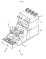
- FIGS. 1A, B, C, D, E and 2A . B . C . D . e . F is a disposable bioreactor 1 or a biotechnological device with a disposable bioreactor, a connection device and a tempering device for use in a in Fig. 3 illustrated parallel bioreactor system 10 for use in cell culture and / or in microbiology.
- This in Fig. 3 shown parallel bioreactor 10 has a base block 11 with four receptacles 12 disposed therein, in each of which a bioreactor 1 can be releasably inserted.
- a temperature control is preferably arranged, which is designed to heat or cool the disposable bioreactors 1 arranged in the receptacles 12 as required. Adjacent to the base block 11, an arrangement with containers 13 is formed. Furthermore, the base block 11 has a stacking surface on which two functional blocks 14, 15 are arranged detachably in a stack formation and designed, for example, as a gas mixing station or pump station are, for example, to supply or remove the necessary for the operation of bioreactors fluids.
- Such a parallel bioreactor system 10 has the advantage of a small footprint and a high scalability, since several of these parallel bioreactor 10, each with four disposable bioreactors 1 can be arranged side by side.
- the disposable bioreactors 1 have the advantage of being able to be used in such a parallel bioreactor system for use in cell culture and / or microbiology as reusable bioreactors.
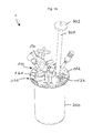
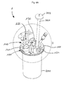
- the disposable bioreactor 1 has a top plate 100, a dimensionally stable container 200 and a stirrer 300.
- the top plate 100 and the container 200 include a reaction space 400.
- the top plate 100 has an inner side 101 facing the reaction space, on which a plurality of dip tubes 110 are arranged, which projects into the reaction space 400.
- On a side facing away from the reaction space 400 outside 102 of the top plate 100 a plurality of terminals 120 are arranged.
- the agitator 300 has a stirring shaft 310 with a rotation axis and a stirring element 320.
- the stirring element 320 is here designed with wings inclined by 45 °, for example as a pitch blade impeller. Alternatively, for example, at least one Rushton impeller can also be used as the stirring element.
- the stirring element 320 is rigidly attached to the agitator shaft 310, so that rotates upon rotation of the agitator shaft 310 to the stirring member 320.
- the top plate 100 and the container 200 are preferably formed of polyamide and non-detachably connected to each other by ultrasonic welding.
- the agitator 300 in particular the tube shaft 310 and / or the stirring element 320, are preferably made of polystyrene. Polystyrene has a lower temperature resistance than polyamide, so that in a hot steam sterilization of the disposable bioreactor 1, the agitator 300 is rendered unusable and thus reuse of the disposable bioreactor 1 is excluded.
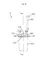
- the agitator shaft 310 is rotatably mounted about the rotation axis in a bearing 500.
- the bearing 500 is arranged in a bulge 130 of the top plate 100.
- a bearing housing 510 delimits a storage space 520 in the reaction space 400.
- the bearing housing 510 is sealed against the agitator shaft 310 via a plain bearing bushing 530.
- the entire bearing housing may be made of a material suitable for sliding bearing. This has the advantage of an item reduction and a high degree of integration, which also has an advantageous effect in the production and assembly.
- the bearing 500 is designed as a roller bearing and preferably has a polymer ball bearing 501 with a cage made of polyethylene, polypropylene, polyvinylidene fluoride, polyetheretherketone or polytetrafluoroethylene and glass beads 502 on.
- the stirring shaft 310 has a magnetic portion 311, 311 ', which is magnetically coupled in an axial direction with a rotary drive 600.
- the magnetic section 311, 311 'of the stirrer shaft 310 is magnetically coupled to the front side, ie in the axial direction, with a rotary drive 600.
- the rotary drive 600 has a substantially cylindrical shape and has a cross-sectional area which substantially corresponds to the cross-sectional area of the bulge 130 on the top plate 100.
- a driving member 613 drives a magnetic driving portion 611; 611 'on.
- axial magnetic coupling has the advantage of a particularly small footprint for the drive on the top plate.
- a magnetic section 311 is arranged at the end of the agitator shaft 310, in which magnets 312 are arranged, preferably in an annular arrangement.
- the magnetic section 311 with the magnets 312 arranged therein is connected in a torsionally rigid manner to the stirrer shaft 310 via a hexagonal nut 313.
- Magnets may also be arranged in the magnetic drive section 611 of the rotary drive, the arrangement of which is preferably aligned with the arrangement of the magnets 312 of the magnetic section 311 of the stirring shaft 310.
- the magnetic portion 311 ' has a cross section in a plane orthogonal to the agitator shaft 31, and has a magnetic force for magnetic coupling in the axial direction with a rotary drive 600 over most of this cross section, preferably over the entire cross section.
- the cross section of the magnetic portion 311 'with magnetic force effect is preferably circular here and preferably has segments 315a, b of different polarity, which form, for example, a star-shaped pattern or a pattern with pie-shaped segments.
- the magnetic drive section 611 'of the rotary drive 600 has a cross-section in a plane orthogonal to a rotation axis, and has over the majority of this cross section, preferably over the entire cross section, a magnetic force action for a magnetic coupling in the axial direction with the magnetic portion 311 'of the agitator shaft 310 on.
- the cross-section of the magnetic drive force magnetic drive section 611 ' is here preferably circular and preferably has segments 615 of different polarity, which for example form a star-shaped pattern or a pattern with pie-shaped segments.
- the pattern of the segments 615 of the magnetic drive section 611 ' is preferably matched to the pattern of the segments 315a, b of the magnetic section 311' of the stirring shaft 310.
- the magnetic portion 311 'and / or the magnetic drive portion 611' is or are preferably made of a composite or two-component material, in particular a magnet-polymer mixture, and further preferably produced by injection molding.
- the magnetic section 311 'and / or the magnetic drive section 611' can be configured as separate parts which are arranged on the agitator shaft 310 or the drive element 613 and are fastened there, possibly releasably.
- an integral formation of the magnetic portion 311 'with the agitator shaft 310 preferably by spraying a composite or two-component material, in particular a magnet-polymer mixture, on one end of the agitator shaft 310.
- a composite or two-component material in particular a magnet-polymer mixture
- a one-piece design of the magnetic drive section 611 'with a drive element 613 preferably by spraying a composite or two-component material, in particular a magnet-polymer mixture, onto the drive element 613.
- top plate 100 is preferably formed in one piece and made by injection molding of preferably polyamide including arranged on the outside of ports 120 and the inside arranged dip tubes 110.
- the dip tubes 110 correspond to a portion of the terminals 120, so through the corresponding terminals 120 instruments, Sensors, lines, such as hoses through the dip tubes 110 in the reaction chamber on or can be performed.
- the connections 120 are used to provide the substances necessary for the reaction process and / or to remove substances from the reaction space 400, for example gases produced during operation.
- the ports 120 may also be referred to as overlays and the dip tubes 110 as submersibles.
- connection 123 serves, for example, to be connected to an exhaust gas hose 701, at the end of which an exhaust gas sterile filter 702 is again arranged.
- a discharged through the exhaust hose 701 gas stream can be treated, for example, by another device, preferably tempered.
- the sterile filter 702 serves to filter the exhaust gas before it exits.
- a connection slot 124 is formed by two U-shaped profiles, which are particularly suitable for receiving an exhaust gas cooling element 700.
- the exhaust gas cooling element 700 may in particular be designed as a tempering element, as described in the applicant's copending application of the same date entitled "Device for a sterile disposable fluid line of a disposable bioreactor and method for treating a fluid flow".
- Such a cooling element 700 serves to cool the exhaust gas in the tube 701 and condense liquid entrained therein, which then, preferably by gravity, can be returned to the reaction space 400 and thus again on the one hand in the reaction space available and on the other hand, the sterile filter 702 not clogged.
- the terminals 120 may be formed, for example, as screw connections 121 with an internal thread, as clamping type connections 122 or as conical connections 125.
- Unused ports 120 may be sealed for use, such as for the two screw ports 121 in FIG Fig. 1A and 4A, B is shown.
- Fig. 5A, B, C three lying between the two screw terminals 121 conical terminals 125 to recognize where in the Fig. 4A .
- B Hoses are attached. In the in Fig.
- the rear of the two screw terminals 121 ' is closed with a cap, whereas the front of the two screw terminals 121 carries a functional element.
- a functional element for example, pH or DO (Dissolved Oxygen), temperature or other sensors can be arranged on the connections 120 and preferably introduced into the reaction space via the dip tubes 110.
- the two screw terminals 121 are preferably formed as a PG 13.5 thread.
- a particularly preferred combination of ports 120 of a top plate 100 includes two screw ports formed as PG 13.5 threads, gas ports for headspace and sub-water (or sub-media) gas supply, an exhaust port and a connector for exhaust gas cooling Sampling connection with a sampling valve, such as a swabable valve, a fluid port, two dip tubes, a resistance temperature detector (T or RTD) port, and a dissolved oxygen (DO) sensor port with a permeable membrane.
- a sampling valve such as a swabable valve
- a fluid port such as a swabable valve
- T or RTD resistance temperature detector
- DO dissolved oxygen
- Hoses and fittings used with the disposable bioreactor 1 which may come into contact with reaction media are preferably formed from materials certified to United States Pharmacopeia (USP) Class VI, such as polystyrene, polycarbonate, polyamide or silicone.
- USP United States Pharmacopeia
- the hoses to be used are preferably flexible hoses made of thermoplastic elastomers.
Landscapes
- Health & Medical Sciences (AREA)
- Wood Science & Technology (AREA)
- Organic Chemistry (AREA)
- Life Sciences & Earth Sciences (AREA)
- Engineering & Computer Science (AREA)
- Bioinformatics & Cheminformatics (AREA)
- Chemical & Material Sciences (AREA)
- Zoology (AREA)
- Biomedical Technology (AREA)
- Sustainable Development (AREA)
- Microbiology (AREA)
- Biotechnology (AREA)
- Biochemistry (AREA)
- General Engineering & Computer Science (AREA)
- General Health & Medical Sciences (AREA)
- Genetics & Genomics (AREA)
- Clinical Laboratory Science (AREA)
- Apparatus Associated With Microorganisms And Enzymes (AREA)
- Mixers Of The Rotary Stirring Type (AREA)
- Mixers With Rotating Receptacles And Mixers With Vibration Mechanisms (AREA)
- Accessories For Mixers (AREA)
Priority Applications (9)
| Application Number | Priority Date | Filing Date | Title |
|---|---|---|---|
| DK12172304.3T DK2674479T3 (en) | 2012-06-15 | 2012-06-15 | One-way bioreactor and top plate and method of manufacture |
| EP12172304.3A EP2674479B1 (fr) | 2012-06-15 | 2012-06-15 | Bioréacteur jetable et plaque frontale, ainsi que procédés de fabrication |
| PCT/EP2013/062225 WO2013186294A1 (fr) | 2012-06-15 | 2013-06-13 | Bioréacteur à usage unique et plaque de tête, et son procédé de fabrication |
| DK13730518.1T DK2861711T3 (da) | 2012-06-15 | 2013-06-13 | Engangsbioreaktor og hovedplade, og en fremgangsmåde til fremstilling deraf |
| CN201380031555.6A CN104379722B (zh) | 2012-06-15 | 2013-06-13 | 一次性使用的生物反应器和顶板以及它们的制造方法 |
| EP13730518.1A EP2861711B1 (fr) | 2012-06-15 | 2013-06-13 | Bioréacteur jetable et plaque frontale, ainsi que procédés de fabrication |
| US14/408,069 US10030220B2 (en) | 2012-06-15 | 2013-06-13 | Single-use bioreactor and head plate, and a process for manufacturing same |
| JP2015516610A JP6227636B2 (ja) | 2012-06-15 | 2013-06-13 | 使い捨てバイオリアクタおよびヘッドプレート、並びにそれらを製造するプロセス |
| JP2017150939A JP6527919B2 (ja) | 2012-06-15 | 2017-08-03 | 使い捨てバイオリアクタおよびヘッドプレート、並びにそれらを製造するプロセス |
Applications Claiming Priority (1)
| Application Number | Priority Date | Filing Date | Title |
|---|---|---|---|
| EP12172304.3A EP2674479B1 (fr) | 2012-06-15 | 2012-06-15 | Bioréacteur jetable et plaque frontale, ainsi que procédés de fabrication |
Publications (2)
| Publication Number | Publication Date |
|---|---|
| EP2674479A1 true EP2674479A1 (fr) | 2013-12-18 |
| EP2674479B1 EP2674479B1 (fr) | 2015-03-18 |
Family
ID=46319599
Family Applications (2)
| Application Number | Title | Priority Date | Filing Date |
|---|---|---|---|
| EP12172304.3A Active EP2674479B1 (fr) | 2012-06-15 | 2012-06-15 | Bioréacteur jetable et plaque frontale, ainsi que procédés de fabrication |
| EP13730518.1A Active EP2861711B1 (fr) | 2012-06-15 | 2013-06-13 | Bioréacteur jetable et plaque frontale, ainsi que procédés de fabrication |
Family Applications After (1)
| Application Number | Title | Priority Date | Filing Date |
|---|---|---|---|
| EP13730518.1A Active EP2861711B1 (fr) | 2012-06-15 | 2013-06-13 | Bioréacteur jetable et plaque frontale, ainsi que procédés de fabrication |
Country Status (6)
| Country | Link |
|---|---|
| US (1) | US10030220B2 (fr) |
| EP (2) | EP2674479B1 (fr) |
| JP (2) | JP6227636B2 (fr) |
| CN (1) | CN104379722B (fr) |
| DK (2) | DK2674479T3 (fr) |
| WO (1) | WO2013186294A1 (fr) |
Cited By (7)
| Publication number | Priority date | Publication date | Assignee | Title |
|---|---|---|---|---|
| WO2016198185A1 (fr) * | 2015-06-10 | 2016-12-15 | Human Med Ag | Dispositif pour séparer des cellules souches régénératrices et adultes |
| WO2017025210A1 (fr) * | 2015-08-08 | 2017-02-16 | Stobbe Pharma Tech Gmbh | Système jetable de bioprocédé supportant une activité biologique |
| WO2017129800A1 (fr) * | 2016-01-29 | 2017-08-03 | Eppendorf Ag | Dispositif de raccordement à usage unique |
| WO2018077627A1 (fr) | 2016-10-28 | 2018-05-03 | Trace Analytics Gmbh | Sonde à deux orifices de prélèvement |
| EP3514223A1 (fr) * | 2018-01-17 | 2019-07-24 | Eppendorf AG | Multicapteur pour un bioréacteur, bioréacteur, procédé de fabrication d'un multicapteur et de mesure de paramètres |
| US10717960B2 (en) | 2011-10-10 | 2020-07-21 | Dasgip Information And Technology Gmbh | Biotechnological apparatus comprising a bioreactor, exhaust gas temperature control device for a bioreactor and a method for treating an exhaust gas stream in a biotechnological apparatus |
| EP3839035A1 (fr) * | 2019-12-18 | 2021-06-23 | Eppendorf AG | Bioréacteur, plaque de tête pour un bioréacteur et unité de transfert des données pour une plaque de tête |
Families Citing this family (11)
| Publication number | Priority date | Publication date | Assignee | Title |
|---|---|---|---|---|
| DK2766468T3 (da) | 2011-10-10 | 2019-05-06 | Dasgip Information And Process Tech Gmbh | Fremgangsmåde til kontrolleret drift af en bioteknologisk indretning og bioreaktorsystemer |
| US10836989B2 (en) * | 2015-10-16 | 2020-11-17 | Global Life Sciences Solutions Usa Llc | Disposable container, mixing system and packaging |
| US11613724B2 (en) * | 2015-12-10 | 2023-03-28 | Rosemount Inc. | Single-use bioreactor sensor interface |
| CN108018204A (zh) | 2016-11-03 | 2018-05-11 | 浙江金仪盛世生物工程有限公司 | 一种平行生物反应器系统 |
| US11136541B2 (en) | 2016-12-28 | 2021-10-05 | Zhejiang Jinyishengshi Bioengineering Co., Ltd. | Parallel bioreactor system |
| WO2019097500A1 (fr) * | 2017-11-20 | 2019-05-23 | Willis Michael Jared | Photoréacteur destiné à l'analyse de cellules et à des réactions chimiques et biochimiques en réseau |
| GB201719769D0 (en) | 2017-11-28 | 2018-01-10 | Cronin 3D Ltd | Analytical device and methods of use |
| NL2021470B1 (en) | 2018-08-15 | 2020-02-24 | Applikon Biotechnology B V | Lid configuration for a bioreactor |
| EP3924097A4 (fr) * | 2019-02-11 | 2022-11-16 | Culture Biosciences, Inc. | Récipient de bioréacteur pour système de fermentation automatisé |
| EP3763807A1 (fr) * | 2019-07-12 | 2021-01-13 | Eppendorf AG | Port multi-connecteur |
| CN111534420A (zh) * | 2020-04-07 | 2020-08-14 | 天津大学 | 一种生物反应器 |
Citations (23)
| Publication number | Priority date | Publication date | Assignee | Title |
|---|---|---|---|---|
| WO2003006633A1 (fr) * | 2001-07-09 | 2003-01-23 | Alcan Packaging Pharmaceutical And Personal Care Inc. | Recipient jetable |
| DE202007005868U1 (de) | 2006-05-10 | 2007-07-19 | Sartorius Ag | Bioreaktor |
| US20070253288A1 (en) | 2006-04-28 | 2007-11-01 | Sartorius Ag | Container having flexible walls |
| WO2007134267A2 (fr) * | 2006-05-13 | 2007-11-22 | Advanced Technology Materials, Inc. | Bioréacteur jetable |
| US20080131957A1 (en) * | 2006-11-30 | 2008-06-05 | Ryan John A | Disposable spinner flask |
| WO2008088379A2 (fr) | 2006-07-14 | 2008-07-24 | Xcellerex, Inc. | Systèmes de confinement environnemental |
| WO2009009771A1 (fr) * | 2007-07-12 | 2009-01-15 | Oldenburg Kevin R | Flacon rotatif jetable |
| EP2065085A1 (fr) * | 2007-11-30 | 2009-06-03 | Levitronix GmbH | Dispositif de mélange et récipient stérile le comportant |
| US20090152744A1 (en) * | 2007-12-17 | 2009-06-18 | Duen Gang Mou | Reaction vessel assembly with gas exchange means |
| US20090275121A1 (en) | 2006-05-11 | 2009-11-05 | Sartorius Stedim Biotech Gmbh | Vibrational Mixer |
| DE102008027638A1 (de) * | 2008-06-06 | 2009-12-10 | Sann, Heiner, Dr. | Disposable Vorrichtung und Verfahren zur Abluftkühlung, Luftfeuchtereduzierung und Schaumreduzierung |
| US20090311776A1 (en) | 2008-06-11 | 2009-12-17 | Millipore Corporation | Stirred tank bioreactor |
| US20100028990A1 (en) | 2007-02-15 | 2010-02-04 | Broadley-James Corporation | Sterile bioreactor bag with integrated drive unit |
| DE202009015434U1 (de) * | 2008-12-05 | 2010-04-08 | Sartorius Stedim Biotech Gmbh | Verschluss für einen Behälter |
| EP2251407A1 (fr) | 2009-05-12 | 2010-11-17 | Eppendorf Ag | Bioréacteur jetable, son kit et son procédé de production |
| US20110003374A1 (en) | 2008-02-21 | 2011-01-06 | Sartorius Stedim Biotech Gmbh | Bioreactor |
| US20110058447A1 (en) | 2008-05-28 | 2011-03-10 | Sartorius Stedim Biotech Gmbh | Mixing system |
| US20110058448A1 (en) | 2008-05-28 | 2011-03-10 | Sartorius Stedim Biotech Gmbh | Mixing system |
| DE102009056468A1 (de) * | 2009-12-01 | 2011-06-09 | Technische Universität München | Rührorgan für Milliliter-Bioreaktoren |
| WO2011079180A1 (fr) | 2009-12-23 | 2011-06-30 | Ge Healthcare Bio-Sciences Corp. | Bioréacteurs améliorés |
| US20110207218A1 (en) | 2010-02-22 | 2011-08-25 | Hyclone Laboratories, Inc. | Mixing system with condenser |
| US20110207170A1 (en) * | 2011-05-01 | 2011-08-25 | Therapeutic Proteins Inc | Bioreactor Exhaust |
| US20120003733A1 (en) | 2009-03-18 | 2012-01-05 | Sartorius Stedim Biotech S.A. | Mixing container comprising a shaft bearing in the upper part |
Family Cites Families (12)
| Publication number | Priority date | Publication date | Assignee | Title |
|---|---|---|---|---|
| JPS643482Y2 (fr) * | 1984-12-19 | 1989-01-30 | ||
| CN1171989C (zh) | 2002-07-13 | 2004-10-20 | 华中科技大学 | 一种生物反应器 |
| US9109193B2 (en) * | 2007-07-30 | 2015-08-18 | Ge Healthcare Bio-Sciences Corp. | Continuous perfusion bioreactor system |
| US8690129B2 (en) | 2008-03-19 | 2014-04-08 | Sartorius Stedim Biotech Gmbh | Disposable mixing vessel |
| US8281672B2 (en) | 2009-03-20 | 2012-10-09 | Pbs Biotech, Inc. | Automatable aseptic sample withdrawal system |
| CN201419084Y (zh) * | 2009-04-07 | 2010-03-10 | 上海森松制药设备工程有限公司 | 用于生物反应器的磁力搅拌装置 |
| DE202010007640U1 (de) | 2009-06-16 | 2010-08-19 | Sartorius Stedim Biotech Gmbh | Behälter mit einem Sensoradapter |
| JP2011098259A (ja) * | 2009-11-04 | 2011-05-19 | Fox Kagaku:Kk | 微小型攪拌造粒装置 |
| CN201565273U (zh) * | 2009-12-02 | 2010-09-01 | 上海化工研究院 | 一种磁力搅拌反应釜 |
| JP5570913B2 (ja) * | 2010-08-27 | 2014-08-13 | 株式会社日立製作所 | 生体細胞の培養容器及び培養装置 |
| DE102011054363B4 (de) | 2011-10-10 | 2015-07-09 | DASGIP Information and Process Technology GmbH | Verfahren zum geregelten Betreiben einer biotechnologischen Vorrichtung und biotechnologische Vorrichtung |
| DE102011054365B4 (de) | 2011-10-10 | 2014-01-02 | DASGIP Information and Process Technology GmbH | Biotechnologische Vorrichtung, Bioreaktorsystem mit mehreren biotechnologischen Vorrichtungen, Verfahren zum Temperieren eines Kultivierungsraumes in einer biotechnologischen Vorrichtung sowie Verfahren zum Temperieren von Kultivierungsräumen in einem Bioreaktorsystem |
-
2012
- 2012-06-15 EP EP12172304.3A patent/EP2674479B1/fr active Active
- 2012-06-15 DK DK12172304.3T patent/DK2674479T3/en active
-
2013
- 2013-06-13 DK DK13730518.1T patent/DK2861711T3/da active
- 2013-06-13 WO PCT/EP2013/062225 patent/WO2013186294A1/fr active Application Filing
- 2013-06-13 US US14/408,069 patent/US10030220B2/en active Active
- 2013-06-13 CN CN201380031555.6A patent/CN104379722B/zh active Active
- 2013-06-13 JP JP2015516610A patent/JP6227636B2/ja not_active Expired - Fee Related
- 2013-06-13 EP EP13730518.1A patent/EP2861711B1/fr active Active
-
2017
- 2017-08-03 JP JP2017150939A patent/JP6527919B2/ja active Active
Patent Citations (23)
| Publication number | Priority date | Publication date | Assignee | Title |
|---|---|---|---|---|
| WO2003006633A1 (fr) * | 2001-07-09 | 2003-01-23 | Alcan Packaging Pharmaceutical And Personal Care Inc. | Recipient jetable |
| US20070253288A1 (en) | 2006-04-28 | 2007-11-01 | Sartorius Ag | Container having flexible walls |
| DE202007005868U1 (de) | 2006-05-10 | 2007-07-19 | Sartorius Ag | Bioreaktor |
| US20090275121A1 (en) | 2006-05-11 | 2009-11-05 | Sartorius Stedim Biotech Gmbh | Vibrational Mixer |
| WO2007134267A2 (fr) * | 2006-05-13 | 2007-11-22 | Advanced Technology Materials, Inc. | Bioréacteur jetable |
| WO2008088379A2 (fr) | 2006-07-14 | 2008-07-24 | Xcellerex, Inc. | Systèmes de confinement environnemental |
| US20080131957A1 (en) * | 2006-11-30 | 2008-06-05 | Ryan John A | Disposable spinner flask |
| US20100028990A1 (en) | 2007-02-15 | 2010-02-04 | Broadley-James Corporation | Sterile bioreactor bag with integrated drive unit |
| WO2009009771A1 (fr) * | 2007-07-12 | 2009-01-15 | Oldenburg Kevin R | Flacon rotatif jetable |
| EP2065085A1 (fr) * | 2007-11-30 | 2009-06-03 | Levitronix GmbH | Dispositif de mélange et récipient stérile le comportant |
| US20090152744A1 (en) * | 2007-12-17 | 2009-06-18 | Duen Gang Mou | Reaction vessel assembly with gas exchange means |
| US20110003374A1 (en) | 2008-02-21 | 2011-01-06 | Sartorius Stedim Biotech Gmbh | Bioreactor |
| US20110058447A1 (en) | 2008-05-28 | 2011-03-10 | Sartorius Stedim Biotech Gmbh | Mixing system |
| US20110058448A1 (en) | 2008-05-28 | 2011-03-10 | Sartorius Stedim Biotech Gmbh | Mixing system |
| DE102008027638A1 (de) * | 2008-06-06 | 2009-12-10 | Sann, Heiner, Dr. | Disposable Vorrichtung und Verfahren zur Abluftkühlung, Luftfeuchtereduzierung und Schaumreduzierung |
| US20090311776A1 (en) | 2008-06-11 | 2009-12-17 | Millipore Corporation | Stirred tank bioreactor |
| DE202009015434U1 (de) * | 2008-12-05 | 2010-04-08 | Sartorius Stedim Biotech Gmbh | Verschluss für einen Behälter |
| US20120003733A1 (en) | 2009-03-18 | 2012-01-05 | Sartorius Stedim Biotech S.A. | Mixing container comprising a shaft bearing in the upper part |
| EP2251407A1 (fr) | 2009-05-12 | 2010-11-17 | Eppendorf Ag | Bioréacteur jetable, son kit et son procédé de production |
| DE102009056468A1 (de) * | 2009-12-01 | 2011-06-09 | Technische Universität München | Rührorgan für Milliliter-Bioreaktoren |
| WO2011079180A1 (fr) | 2009-12-23 | 2011-06-30 | Ge Healthcare Bio-Sciences Corp. | Bioréacteurs améliorés |
| US20110207218A1 (en) | 2010-02-22 | 2011-08-25 | Hyclone Laboratories, Inc. | Mixing system with condenser |
| US20110207170A1 (en) * | 2011-05-01 | 2011-08-25 | Therapeutic Proteins Inc | Bioreactor Exhaust |
Cited By (13)
| Publication number | Priority date | Publication date | Assignee | Title |
|---|---|---|---|---|
| US10717960B2 (en) | 2011-10-10 | 2020-07-21 | Dasgip Information And Technology Gmbh | Biotechnological apparatus comprising a bioreactor, exhaust gas temperature control device for a bioreactor and a method for treating an exhaust gas stream in a biotechnological apparatus |
| WO2016198185A1 (fr) * | 2015-06-10 | 2016-12-15 | Human Med Ag | Dispositif pour séparer des cellules souches régénératrices et adultes |
| US11414642B2 (en) | 2015-08-08 | 2022-08-16 | Stobbe Gmbh | Disposable bioprocess system supporting biological activity |
| WO2017025210A1 (fr) * | 2015-08-08 | 2017-02-16 | Stobbe Pharma Tech Gmbh | Système jetable de bioprocédé supportant une activité biologique |
| US12110484B2 (en) | 2015-08-08 | 2024-10-08 | Stobbe Gmbh | Disposable bioprocess system supporting biological activity |
| WO2017129800A1 (fr) * | 2016-01-29 | 2017-08-03 | Eppendorf Ag | Dispositif de raccordement à usage unique |
| US11608484B2 (en) | 2016-01-29 | 2023-03-21 | Eppendorf Ag | Single-use connection device |
| EP3199616B1 (fr) * | 2016-01-29 | 2024-08-21 | Eppendorf SE | Dispositif de connexion a une voie |
| WO2018077627A1 (fr) | 2016-10-28 | 2018-05-03 | Trace Analytics Gmbh | Sonde à deux orifices de prélèvement |
| EP3514223A1 (fr) * | 2018-01-17 | 2019-07-24 | Eppendorf AG | Multicapteur pour un bioréacteur, bioréacteur, procédé de fabrication d'un multicapteur et de mesure de paramètres |
| WO2019141466A1 (fr) * | 2018-01-17 | 2019-07-25 | Eppendorf Ag | Multicapteur pour un bioréacteur, bioréacteur, procédé de fabrication d'un multicapteur et de mesure de paramètres |
| EP3839035A1 (fr) * | 2019-12-18 | 2021-06-23 | Eppendorf AG | Bioréacteur, plaque de tête pour un bioréacteur et unité de transfert des données pour une plaque de tête |
| WO2021122334A1 (fr) * | 2019-12-18 | 2021-06-24 | Eppendorf Ag | Bioréacteur, plaque d'extrémité pour un bioréacteur et unité de communication de données pour une plaque d'extrémité |
Also Published As
| Publication number | Publication date |
|---|---|
| DK2674479T3 (en) | 2015-04-13 |
| WO2013186294A1 (fr) | 2013-12-19 |
| JP2017225454A (ja) | 2017-12-28 |
| US10030220B2 (en) | 2018-07-24 |
| JP6227636B2 (ja) | 2017-11-08 |
| EP2861711A1 (fr) | 2015-04-22 |
| JP6527919B2 (ja) | 2019-06-12 |
| CN104379722A (zh) | 2015-02-25 |
| EP2861711B1 (fr) | 2022-07-20 |
| JP2015525073A (ja) | 2015-09-03 |
| EP2674479B1 (fr) | 2015-03-18 |
| DK2861711T3 (da) | 2022-08-01 |
| CN104379722B (zh) | 2018-11-09 |
| US20150132840A1 (en) | 2015-05-14 |
Similar Documents
| Publication | Publication Date | Title |
|---|---|---|
| EP2674479B1 (fr) | Bioréacteur jetable et plaque frontale, ainsi que procédés de fabrication | |
| EP3408370B1 (fr) | Dispositif de connexion a une voie | |
| EP2898059A1 (fr) | Réservoir de réacteur-flacon à usage unique | |
| EP3120929B1 (fr) | Soupape d'admission pour systemes de chambres et recipients a echantillons ainsi que systemes de chambres dotes de recipients a echantillons dotes de telles soupapes d'admission | |
| EP2948538B1 (fr) | Système de culture de cellules utilisé pour la culture de cellules adhérentes, et interface d'alimentation en fluide à récipient de culture de cellules | |
| EP2817405B1 (fr) | Séparateur à usage unique destiné à la rétention et au retour de cellules | |
| DE202016000554U1 (de) | Einweg-Anschlusseinrichtung | |
| DE102008060773A1 (de) | Verschluss für einen Behälter | |
| DE3905158C2 (fr) | ||
| EP2674480B2 (fr) | Dispositif de raccordement pour la conduite de fluide stérile et à usage unique d'un bioréacteur jetable et procédé pour le traitement d'un flux de liquide | |
| EP3514223A1 (fr) | Multicapteur pour un bioréacteur, bioréacteur, procédé de fabrication d'un multicapteur et de mesure de paramètres | |
| DE102004029709B4 (de) | Vorrichtung und Verfahren zur Zell-Kultivierung in einem Kulturgefäß | |
| EP2875867B1 (fr) | Récipient de culture / récipient à couvercle à visser | |
| DE102011001550A1 (de) | Vorrichtung zum Fördern und Mischen von Mikromengen an Reagenzien und zur Durchführung chemischer Reaktionen | |
| DE3880553T2 (de) | Blutkultursystem. | |
| EP2410042A1 (fr) | Bioréacteur pour la production de microorganismes | |
| WO2022033615A1 (fr) | Dispositif pour un transfert stérile de liquide | |
| DE202011106557U1 (de) | Mikrobiologische Kulturplatte mit integriertem Ausstrichsystem | |
| DE102017115428B4 (de) | Kühlfingervorrichtung für einen Einweg-Behälter | |
| DE202010001635U1 (de) | Mikrobiologische Kulturplatte mit Führungsstegen im unteren Deckelrand und mit einem integrierten Ausstrichsystem | |
| DE202010001636U1 (de) | Mikrobiologische Kulturplatte mit Führungsstiften im unteren Deckelrand und einem integrierten Ausstrichsystem | |
| EP3342486A2 (fr) | Dispositifs et procédés d'exposition aux aérosols | |
| DE2609825A1 (de) | Reaktor fuer biotische reaktionen | |
| WO2011060926A1 (fr) | Dispositif et procédé de culture d'organismes | |
| DE102010019691A1 (de) | Ventil für einen Behälter |
Legal Events
| Date | Code | Title | Description |
|---|---|---|---|
| PUAI | Public reference made under article 153(3) epc to a published international application that has entered the european phase |
Free format text: ORIGINAL CODE: 0009012 |
|
| AK | Designated contracting states |
Kind code of ref document: A1 Designated state(s): AL AT BE BG CH CY CZ DE DK EE ES FI FR GB GR HR HU IE IS IT LI LT LU LV MC MK MT NL NO PL PT RO RS SE SI SK SM TR |
|
| AX | Request for extension of the european patent |
Extension state: BA ME |
|
| RIN1 | Information on inventor provided before grant (corrected) |
Inventor name: SELZER, SEBASTIAN Inventor name: GUELZOW, NICO DIPL.-ING., Inventor name: GUENTHER, CHRISTOPHER DIPL.-ING., Inventor name: EIKELMANN, SVEN DIPL.-ING., Inventor name: KOEHN, HEINZ-GERHARD DR. RER. NAT., Inventor name: ARNOLD, MATTHIAS DR.-ING., Inventor name: BEESE, JOCHEN Inventor name: KOPOWSKI, ECKHART DR.-ING., |
|
| 17P | Request for examination filed |
Effective date: 20140618 |
|
| RBV | Designated contracting states (corrected) |
Designated state(s): AL AT BE BG CH CY CZ DE DK EE ES FI FR GB GR HR HU IE IS IT LI LT LU LV MC MK MT NL NO PL PT RO RS SE SI SK SM TR |
|
| 17Q | First examination report despatched |
Effective date: 20140821 |
|
| GRAP | Despatch of communication of intention to grant a patent |
Free format text: ORIGINAL CODE: EPIDOSNIGR1 |
|
| INTG | Intention to grant announced |
Effective date: 20141112 |
|
| RIN1 | Information on inventor provided before grant (corrected) |
Inventor name: GUELZOW, NICO DIPL.-ING., Inventor name: ARNOLD, MATTHIAS DR.-ING., Inventor name: KOEHN, HEINZ-GERHARD DR. RER. NAT., Inventor name: GUENTHER, CHRISTOPHER DIPL.-ING., Inventor name: EIKELMANN, SVEN DIPL.-ING., Inventor name: BEESE, JOCHEN Inventor name: KOPOWSKI, ECKHART DR.-ING., Inventor name: SELZER, SEBASTIAN DIPL.-ING. |
|
| GRAS | Grant fee paid |
Free format text: ORIGINAL CODE: EPIDOSNIGR3 |
|
| GRAA | (expected) grant |
Free format text: ORIGINAL CODE: 0009210 |
|
| STAA | Information on the status of an ep patent application or granted ep patent |
Free format text: STATUS: THE PATENT HAS BEEN GRANTED |
|
| AK | Designated contracting states |
Kind code of ref document: B1 Designated state(s): AL AT BE BG CH CY CZ DE DK EE ES FI FR GB GR HR HU IE IS IT LI LT LU LV MC MK MT NL NO PL PT RO RS SE SI SK SM TR |
|
| REG | Reference to a national code |
Ref country code: GB Ref legal event code: FG4D Free format text: NOT ENGLISH |
|
| REG | Reference to a national code |
Ref country code: CH Ref legal event code: EP |
|
| REG | Reference to a national code |
Ref country code: IE Ref legal event code: FG4D Free format text: LANGUAGE OF EP DOCUMENT: GERMAN |
|
| REG | Reference to a national code |
Ref country code: DK Ref legal event code: T3 Effective date: 20150409 |
|
| REG | Reference to a national code |
Ref country code: AT Ref legal event code: REF Ref document number: 716589 Country of ref document: AT Kind code of ref document: T Effective date: 20150415 Ref country code: CH Ref legal event code: NV Representative=s name: RENTSCH PARTNER AG, CH |
|
| REG | Reference to a national code |
Ref country code: DE Ref legal event code: R096 Ref document number: 502012002551 Country of ref document: DE Effective date: 20150430 |
|
| REG | Reference to a national code |
Ref country code: FR Ref legal event code: PLFP Year of fee payment: 4 |
|
| REG | Reference to a national code |
Ref country code: NO Ref legal event code: T2 Effective date: 20150318 |
|
| REG | Reference to a national code |
Ref country code: NL Ref legal event code: VDEP Effective date: 20150318 |
|
| REG | Reference to a national code |
Ref country code: NL Ref legal event code: VDEP Effective date: 20150318 |
|
| PG25 | Lapsed in a contracting state [announced via postgrant information from national office to epo] |
Ref country code: LT Free format text: LAPSE BECAUSE OF FAILURE TO SUBMIT A TRANSLATION OF THE DESCRIPTION OR TO PAY THE FEE WITHIN THE PRESCRIBED TIME-LIMIT Effective date: 20150318 Ref country code: FI Free format text: LAPSE BECAUSE OF FAILURE TO SUBMIT A TRANSLATION OF THE DESCRIPTION OR TO PAY THE FEE WITHIN THE PRESCRIBED TIME-LIMIT Effective date: 20150318 Ref country code: SE Free format text: LAPSE BECAUSE OF FAILURE TO SUBMIT A TRANSLATION OF THE DESCRIPTION OR TO PAY THE FEE WITHIN THE PRESCRIBED TIME-LIMIT Effective date: 20150318 Ref country code: HR Free format text: LAPSE BECAUSE OF FAILURE TO SUBMIT A TRANSLATION OF THE DESCRIPTION OR TO PAY THE FEE WITHIN THE PRESCRIBED TIME-LIMIT Effective date: 20150318 |
|
| REG | Reference to a national code |
Ref country code: LT Ref legal event code: MG4D |
|
| PG25 | Lapsed in a contracting state [announced via postgrant information from national office to epo] |
Ref country code: GR Free format text: LAPSE BECAUSE OF FAILURE TO SUBMIT A TRANSLATION OF THE DESCRIPTION OR TO PAY THE FEE WITHIN THE PRESCRIBED TIME-LIMIT Effective date: 20150619 Ref country code: LV Free format text: LAPSE BECAUSE OF FAILURE TO SUBMIT A TRANSLATION OF THE DESCRIPTION OR TO PAY THE FEE WITHIN THE PRESCRIBED TIME-LIMIT Effective date: 20150318 Ref country code: RS Free format text: LAPSE BECAUSE OF FAILURE TO SUBMIT A TRANSLATION OF THE DESCRIPTION OR TO PAY THE FEE WITHIN THE PRESCRIBED TIME-LIMIT Effective date: 20150318 |
|
| PG25 | Lapsed in a contracting state [announced via postgrant information from national office to epo] |
Ref country code: NL Free format text: LAPSE BECAUSE OF FAILURE TO SUBMIT A TRANSLATION OF THE DESCRIPTION OR TO PAY THE FEE WITHIN THE PRESCRIBED TIME-LIMIT Effective date: 20150318 |
|
| PG25 | Lapsed in a contracting state [announced via postgrant information from national office to epo] |
Ref country code: SK Free format text: LAPSE BECAUSE OF FAILURE TO SUBMIT A TRANSLATION OF THE DESCRIPTION OR TO PAY THE FEE WITHIN THE PRESCRIBED TIME-LIMIT Effective date: 20150318 Ref country code: ES Free format text: LAPSE BECAUSE OF FAILURE TO SUBMIT A TRANSLATION OF THE DESCRIPTION OR TO PAY THE FEE WITHIN THE PRESCRIBED TIME-LIMIT Effective date: 20150318 Ref country code: RO Free format text: LAPSE BECAUSE OF FAILURE TO SUBMIT A TRANSLATION OF THE DESCRIPTION OR TO PAY THE FEE WITHIN THE PRESCRIBED TIME-LIMIT Effective date: 20150318 Ref country code: EE Free format text: LAPSE BECAUSE OF FAILURE TO SUBMIT A TRANSLATION OF THE DESCRIPTION OR TO PAY THE FEE WITHIN THE PRESCRIBED TIME-LIMIT Effective date: 20150318 Ref country code: CZ Free format text: LAPSE BECAUSE OF FAILURE TO SUBMIT A TRANSLATION OF THE DESCRIPTION OR TO PAY THE FEE WITHIN THE PRESCRIBED TIME-LIMIT Effective date: 20150318 Ref country code: PT Free format text: LAPSE BECAUSE OF FAILURE TO SUBMIT A TRANSLATION OF THE DESCRIPTION OR TO PAY THE FEE WITHIN THE PRESCRIBED TIME-LIMIT Effective date: 20150720 |
|
| PG25 | Lapsed in a contracting state [announced via postgrant information from national office to epo] |
Ref country code: PL Free format text: LAPSE BECAUSE OF FAILURE TO SUBMIT A TRANSLATION OF THE DESCRIPTION OR TO PAY THE FEE WITHIN THE PRESCRIBED TIME-LIMIT Effective date: 20150318 Ref country code: IS Free format text: LAPSE BECAUSE OF FAILURE TO SUBMIT A TRANSLATION OF THE DESCRIPTION OR TO PAY THE FEE WITHIN THE PRESCRIBED TIME-LIMIT Effective date: 20150718 |
|
| REG | Reference to a national code |
Ref country code: DE Ref legal event code: R026 Ref document number: 502012002551 Country of ref document: DE |
|
| PLBI | Opposition filed |
Free format text: ORIGINAL CODE: 0009260 |
|
| PG25 | Lapsed in a contracting state [announced via postgrant information from national office to epo] |
Ref country code: IT Free format text: LAPSE BECAUSE OF FAILURE TO SUBMIT A TRANSLATION OF THE DESCRIPTION OR TO PAY THE FEE WITHIN THE PRESCRIBED TIME-LIMIT Effective date: 20150318 |
|
| PLAB | Opposition data, opponent's data or that of the opponent's representative modified |
Free format text: ORIGINAL CODE: 0009299OPPO |
|
| PLAX | Notice of opposition and request to file observation + time limit sent |
Free format text: ORIGINAL CODE: EPIDOSNOBS2 |
|
| 26 | Opposition filed |
Opponent name: SARTORIUS STEDIM BIOTECH GMBH Effective date: 20151217 |
|
| PG25 | Lapsed in a contracting state [announced via postgrant information from national office to epo] |
Ref country code: MC Free format text: LAPSE BECAUSE OF FAILURE TO SUBMIT A TRANSLATION OF THE DESCRIPTION OR TO PAY THE FEE WITHIN THE PRESCRIBED TIME-LIMIT Effective date: 20150318 |
|
| R26 | Opposition filed (corrected) |
Opponent name: SARTORIUS STEDIM BIOTECH GMBH Effective date: 20151217 |
|
| PG25 | Lapsed in a contracting state [announced via postgrant information from national office to epo] |
Ref country code: SI Free format text: LAPSE BECAUSE OF FAILURE TO SUBMIT A TRANSLATION OF THE DESCRIPTION OR TO PAY THE FEE WITHIN THE PRESCRIBED TIME-LIMIT Effective date: 20150318 Ref country code: LU Free format text: LAPSE BECAUSE OF FAILURE TO SUBMIT A TRANSLATION OF THE DESCRIPTION OR TO PAY THE FEE WITHIN THE PRESCRIBED TIME-LIMIT Effective date: 20150615 |
|
| REG | Reference to a national code |
Ref country code: IE Ref legal event code: MM4A |
|
| PG25 | Lapsed in a contracting state [announced via postgrant information from national office to epo] |
Ref country code: IE Free format text: LAPSE BECAUSE OF NON-PAYMENT OF DUE FEES Effective date: 20150615 |
|
| PLBB | Reply of patent proprietor to notice(s) of opposition received |
Free format text: ORIGINAL CODE: EPIDOSNOBS3 |
|
| REG | Reference to a national code |
Ref country code: FR Ref legal event code: PLFP Year of fee payment: 5 |
|
| PLAB | Opposition data, opponent's data or that of the opponent's representative modified |
Free format text: ORIGINAL CODE: 0009299OPPO |
|
| R26 | Opposition filed (corrected) |
Opponent name: SARTORIUS STEDIM BIOTECH GMBH Effective date: 20151217 |
|
| PG25 | Lapsed in a contracting state [announced via postgrant information from national office to epo] |
Ref country code: MT Free format text: LAPSE BECAUSE OF FAILURE TO SUBMIT A TRANSLATION OF THE DESCRIPTION OR TO PAY THE FEE WITHIN THE PRESCRIBED TIME-LIMIT Effective date: 20150318 |
|
| PG25 | Lapsed in a contracting state [announced via postgrant information from national office to epo] |
Ref country code: HU Free format text: LAPSE BECAUSE OF FAILURE TO SUBMIT A TRANSLATION OF THE DESCRIPTION OR TO PAY THE FEE WITHIN THE PRESCRIBED TIME-LIMIT; INVALID AB INITIO Effective date: 20120615 Ref country code: BG Free format text: LAPSE BECAUSE OF FAILURE TO SUBMIT A TRANSLATION OF THE DESCRIPTION OR TO PAY THE FEE WITHIN THE PRESCRIBED TIME-LIMIT Effective date: 20150318 Ref country code: SM Free format text: LAPSE BECAUSE OF FAILURE TO SUBMIT A TRANSLATION OF THE DESCRIPTION OR TO PAY THE FEE WITHIN THE PRESCRIBED TIME-LIMIT Effective date: 20150318 |
|
| REG | Reference to a national code |
Ref country code: FR Ref legal event code: PLFP Year of fee payment: 6 |
|
| PG25 | Lapsed in a contracting state [announced via postgrant information from national office to epo] |
Ref country code: CY Free format text: LAPSE BECAUSE OF FAILURE TO SUBMIT A TRANSLATION OF THE DESCRIPTION OR TO PAY THE FEE WITHIN THE PRESCRIBED TIME-LIMIT Effective date: 20150318 |
|
| PG25 | Lapsed in a contracting state [announced via postgrant information from national office to epo] |
Ref country code: BE Free format text: LAPSE BECAUSE OF NON-PAYMENT OF DUE FEES Effective date: 20150630 |
|
| PG25 | Lapsed in a contracting state [announced via postgrant information from national office to epo] |
Ref country code: TR Free format text: LAPSE BECAUSE OF FAILURE TO SUBMIT A TRANSLATION OF THE DESCRIPTION OR TO PAY THE FEE WITHIN THE PRESCRIBED TIME-LIMIT Effective date: 20150318 |
|
| REG | Reference to a national code |
Ref country code: CH Ref legal event code: PCAR Free format text: NEW ADDRESS: BELLERIVESTRASSE 203 POSTFACH, 8034 ZUERICH (CH) |
|
| REG | Reference to a national code |
Ref country code: FR Ref legal event code: PLFP Year of fee payment: 7 |
|
| PG25 | Lapsed in a contracting state [announced via postgrant information from national office to epo] |
Ref country code: MK Free format text: LAPSE BECAUSE OF FAILURE TO SUBMIT A TRANSLATION OF THE DESCRIPTION OR TO PAY THE FEE WITHIN THE PRESCRIBED TIME-LIMIT Effective date: 20150318 |
|
| REG | Reference to a national code |
Ref country code: AT Ref legal event code: MM01 Ref document number: 716589 Country of ref document: AT Kind code of ref document: T Effective date: 20170615 |
|
| PG25 | Lapsed in a contracting state [announced via postgrant information from national office to epo] |
Ref country code: AL Free format text: LAPSE BECAUSE OF FAILURE TO SUBMIT A TRANSLATION OF THE DESCRIPTION OR TO PAY THE FEE WITHIN THE PRESCRIBED TIME-LIMIT Effective date: 20150318 |
|
| PG25 | Lapsed in a contracting state [announced via postgrant information from national office to epo] |
Ref country code: AT Free format text: LAPSE BECAUSE OF NON-PAYMENT OF DUE FEES Effective date: 20170615 |
|
| APBM | Appeal reference recorded |
Free format text: ORIGINAL CODE: EPIDOSNREFNO |
|
| APBP | Date of receipt of notice of appeal recorded |
Free format text: ORIGINAL CODE: EPIDOSNNOA2O |
|
| APAH | Appeal reference modified |
Free format text: ORIGINAL CODE: EPIDOSCREFNO |
|
| APBM | Appeal reference recorded |
Free format text: ORIGINAL CODE: EPIDOSNREFNO |
|
| APBP | Date of receipt of notice of appeal recorded |
Free format text: ORIGINAL CODE: EPIDOSNNOA2O |
|
| APBQ | Date of receipt of statement of grounds of appeal recorded |
Free format text: ORIGINAL CODE: EPIDOSNNOA3O |
|
| APBQ | Date of receipt of statement of grounds of appeal recorded |
Free format text: ORIGINAL CODE: EPIDOSNNOA3O |
|
| APAH | Appeal reference modified |
Free format text: ORIGINAL CODE: EPIDOSCREFNO |
|
| REG | Reference to a national code |
Ref country code: DE Ref legal event code: R081 Ref document number: 502012002551 Country of ref document: DE Owner name: EPPENDORF SE, DE Free format text: FORMER OWNER: EPPENDORF AG, 22339 HAMBURG, DE |
|
| RAP4 | Party data changed (patent owner data changed or rights of a patent transferred) |
Owner name: EPPENDORF SE |
|
| P01 | Opt-out of the competence of the unified patent court (upc) registered |
Effective date: 20230527 |
|
| PGFP | Annual fee paid to national office [announced via postgrant information from national office to epo] |
Ref country code: CH Payment date: 20230702 Year of fee payment: 12 |
|
| APBU | Appeal procedure closed |
Free format text: ORIGINAL CODE: EPIDOSNNOA9O |
|
| PGFP | Annual fee paid to national office [announced via postgrant information from national office to epo] |
Ref country code: GB Payment date: 20240620 Year of fee payment: 13 |
|
| PGFP | Annual fee paid to national office [announced via postgrant information from national office to epo] |
Ref country code: DE Payment date: 20240619 Year of fee payment: 13 |
|
| PGFP | Annual fee paid to national office [announced via postgrant information from national office to epo] |
Ref country code: DK Payment date: 20240621 Year of fee payment: 13 |
|
| PGFP | Annual fee paid to national office [announced via postgrant information from national office to epo] |
Ref country code: NO Payment date: 20240621 Year of fee payment: 13 Ref country code: FR Payment date: 20240628 Year of fee payment: 13 |