EP2674479A1 - Disposable bioreactor and head plate and production method - Google Patents
Disposable bioreactor and head plate and production method Download PDFInfo
- Publication number
- EP2674479A1 EP2674479A1 EP12172304.3A EP12172304A EP2674479A1 EP 2674479 A1 EP2674479 A1 EP 2674479A1 EP 12172304 A EP12172304 A EP 12172304A EP 2674479 A1 EP2674479 A1 EP 2674479A1
- Authority
- EP
- European Patent Office
- Prior art keywords
- head plate
- disposable bioreactor
- top plate
- bioreactor
- magnetic
- Prior art date
- Legal status (The legal status is an assumption and is not a legal conclusion. Google has not performed a legal analysis and makes no representation as to the accuracy of the status listed.)
- Granted
Links
- 238000004519 manufacturing process Methods 0.000 title claims abstract description 25
- 238000003756 stirring Methods 0.000 claims abstract description 57
- 238000006243 chemical reaction Methods 0.000 claims abstract description 54
- 239000000463 material Substances 0.000 claims description 57
- 238000004113 cell culture Methods 0.000 claims description 21
- 230000008878 coupling Effects 0.000 claims description 17
- 238000010168 coupling process Methods 0.000 claims description 17
- 238000005859 coupling reaction Methods 0.000 claims description 17
- 239000002131 composite material Substances 0.000 claims description 16
- 238000003466 welding Methods 0.000 claims description 16
- 238000001746 injection moulding Methods 0.000 claims description 12
- 239000004033 plastic Substances 0.000 claims description 8
- 229920003023 plastic Polymers 0.000 claims description 8
- 239000000696 magnetic material Substances 0.000 claims description 7
- 229920000642 polymer Polymers 0.000 claims description 7
- 239000011159 matrix material Substances 0.000 claims description 6
- 238000005096 rolling process Methods 0.000 claims description 6
- 239000011521 glass Substances 0.000 claims description 4
- 238000004026 adhesive bonding Methods 0.000 claims description 3
- 239000011324 bead Substances 0.000 claims description 3
- 239000012815 thermoplastic material Substances 0.000 claims description 2
- 238000000034 method Methods 0.000 abstract description 25
- 230000008901 benefit Effects 0.000 description 28
- 238000013461 design Methods 0.000 description 15
- 230000008569 process Effects 0.000 description 15
- 239000007789 gas Substances 0.000 description 14
- 238000005202 decontamination Methods 0.000 description 10
- -1 polyethylene Polymers 0.000 description 10
- 230000001954 sterilising effect Effects 0.000 description 10
- 238000004659 sterilization and disinfection Methods 0.000 description 10
- 239000004952 Polyamide Substances 0.000 description 8
- 230000009477 glass transition Effects 0.000 description 8
- 229920002647 polyamide Polymers 0.000 description 8
- 239000004743 Polypropylene Substances 0.000 description 6
- 230000003588 decontaminative effect Effects 0.000 description 6
- 229920001155 polypropylene Polymers 0.000 description 6
- 239000004793 Polystyrene Substances 0.000 description 5
- 210000004027 cell Anatomy 0.000 description 5
- 230000000694 effects Effects 0.000 description 5
- 239000012530 fluid Substances 0.000 description 5
- 239000004417 polycarbonate Substances 0.000 description 5
- 229920000515 polycarbonate Polymers 0.000 description 5
- 229920002223 polystyrene Polymers 0.000 description 5
- 238000005507 spraying Methods 0.000 description 5
- 238000003860 storage Methods 0.000 description 5
- 239000000126 substance Substances 0.000 description 5
- 238000012549 training Methods 0.000 description 5
- 230000015572 biosynthetic process Effects 0.000 description 4
- 238000001816 cooling Methods 0.000 description 4
- 238000013400 design of experiment Methods 0.000 description 4
- 238000011161 development Methods 0.000 description 4
- 230000018109 developmental process Effects 0.000 description 4
- 238000002156 mixing Methods 0.000 description 4
- 229920000306 polymethylpentene Polymers 0.000 description 4
- 239000011116 polymethylpentene Substances 0.000 description 4
- 238000011165 process development Methods 0.000 description 4
- 238000007789 sealing Methods 0.000 description 4
- 238000011109 contamination Methods 0.000 description 3
- 239000007788 liquid Substances 0.000 description 3
- 230000002906 microbiologic effect Effects 0.000 description 3
- 229920002959 polymer blend Polymers 0.000 description 3
- 238000012827 research and development Methods 0.000 description 3
- 238000005496 tempering Methods 0.000 description 3
- 239000002033 PVDF binder Substances 0.000 description 2
- 239000004696 Poly ether ether ketone Substances 0.000 description 2
- 239000004698 Polyethylene Substances 0.000 description 2
- 230000009471 action Effects 0.000 description 2
- 230000002411 adverse Effects 0.000 description 2
- QVGXLLKOCUKJST-UHFFFAOYSA-N atomic oxygen Chemical compound [O] QVGXLLKOCUKJST-UHFFFAOYSA-N 0.000 description 2
- 238000011138 biotechnological process Methods 0.000 description 2
- 230000008859 change Effects 0.000 description 2
- 238000004140 cleaning Methods 0.000 description 2
- 238000005520 cutting process Methods 0.000 description 2
- 238000002347 injection Methods 0.000 description 2
- 239000007924 injection Substances 0.000 description 2
- 230000010354 integration Effects 0.000 description 2
- 238000005304 joining Methods 0.000 description 2
- 244000005700 microbiome Species 0.000 description 2
- 229910052760 oxygen Inorganic materials 0.000 description 2
- 239000001301 oxygen Substances 0.000 description 2
- 229920002530 polyetherether ketone Polymers 0.000 description 2
- 229920000573 polyethylene Polymers 0.000 description 2
- 229920001343 polytetrafluoroethylene Polymers 0.000 description 2
- 239000004810 polytetrafluoroethylene Substances 0.000 description 2
- 229920002981 polyvinylidene fluoride Polymers 0.000 description 2
- 238000005070 sampling Methods 0.000 description 2
- 241000894006 Bacteria Species 0.000 description 1
- 241000699802 Cricetulus griseus Species 0.000 description 1
- 241000233866 Fungi Species 0.000 description 1
- 241001465754 Metazoa Species 0.000 description 1
- 240000004808 Saccharomyces cerevisiae Species 0.000 description 1
- 238000005299 abrasion Methods 0.000 description 1
- 238000005054 agglomeration Methods 0.000 description 1
- 230000002776 aggregation Effects 0.000 description 1
- QXJJQWWVWRCVQT-UHFFFAOYSA-K calcium;sodium;phosphate Chemical compound [Na+].[Ca+2].[O-]P([O-])([O-])=O QXJJQWWVWRCVQT-UHFFFAOYSA-K 0.000 description 1
- 150000001875 compounds Chemical class 0.000 description 1
- 238000010276 construction Methods 0.000 description 1
- 238000002474 experimental method Methods 0.000 description 1
- 230000005484 gravity Effects 0.000 description 1
- 210000004408 hybridoma Anatomy 0.000 description 1
- 238000007654 immersion Methods 0.000 description 1
- 230000036512 infertility Effects 0.000 description 1
- 238000002844 melting Methods 0.000 description 1
- 230000008018 melting Effects 0.000 description 1
- 239000012528 membrane Substances 0.000 description 1
- 239000002184 metal Substances 0.000 description 1
- 239000000203 mixture Substances 0.000 description 1
- 235000015097 nutrients Nutrition 0.000 description 1
- 238000005457 optimization Methods 0.000 description 1
- 238000012803 optimization experiment Methods 0.000 description 1
- 210000001672 ovary Anatomy 0.000 description 1
- 239000012785 packaging film Substances 0.000 description 1
- 229920006280 packaging film Polymers 0.000 description 1
- 230000001717 pathogenic effect Effects 0.000 description 1
- 229920001296 polysiloxane Polymers 0.000 description 1
- 238000000746 purification Methods 0.000 description 1
- 239000012429 reaction media Substances 0.000 description 1
- 230000009467 reduction Effects 0.000 description 1
- 238000011160 research Methods 0.000 description 1
- 230000011218 segmentation Effects 0.000 description 1
- 239000007787 solid Substances 0.000 description 1
- 229910001220 stainless steel Inorganic materials 0.000 description 1
- 239000010935 stainless steel Substances 0.000 description 1
- 229920002725 thermoplastic elastomer Polymers 0.000 description 1
- 238000010200 validation analysis Methods 0.000 description 1
- 239000002918 waste heat Substances 0.000 description 1
- XLYOFNOQVPJJNP-UHFFFAOYSA-N water Substances O XLYOFNOQVPJJNP-UHFFFAOYSA-N 0.000 description 1
Images


Classifications
-
- C—CHEMISTRY; METALLURGY
- C12—BIOCHEMISTRY; BEER; SPIRITS; WINE; VINEGAR; MICROBIOLOGY; ENZYMOLOGY; MUTATION OR GENETIC ENGINEERING
- C12M—APPARATUS FOR ENZYMOLOGY OR MICROBIOLOGY; APPARATUS FOR CULTURING MICROORGANISMS FOR PRODUCING BIOMASS, FOR GROWING CELLS OR FOR OBTAINING FERMENTATION OR METABOLIC PRODUCTS, i.e. BIOREACTORS OR FERMENTERS
- C12M23/00—Constructional details, e.g. recesses, hinges
- C12M23/28—Constructional details, e.g. recesses, hinges disposable or single use
-
- C—CHEMISTRY; METALLURGY
- C12—BIOCHEMISTRY; BEER; SPIRITS; WINE; VINEGAR; MICROBIOLOGY; ENZYMOLOGY; MUTATION OR GENETIC ENGINEERING
- C12M—APPARATUS FOR ENZYMOLOGY OR MICROBIOLOGY; APPARATUS FOR CULTURING MICROORGANISMS FOR PRODUCING BIOMASS, FOR GROWING CELLS OR FOR OBTAINING FERMENTATION OR METABOLIC PRODUCTS, i.e. BIOREACTORS OR FERMENTERS
- C12M23/00—Constructional details, e.g. recesses, hinges
- C12M23/40—Manifolds; Distribution pieces
-
- C—CHEMISTRY; METALLURGY
- C12—BIOCHEMISTRY; BEER; SPIRITS; WINE; VINEGAR; MICROBIOLOGY; ENZYMOLOGY; MUTATION OR GENETIC ENGINEERING
- C12M—APPARATUS FOR ENZYMOLOGY OR MICROBIOLOGY; APPARATUS FOR CULTURING MICROORGANISMS FOR PRODUCING BIOMASS, FOR GROWING CELLS OR FOR OBTAINING FERMENTATION OR METABOLIC PRODUCTS, i.e. BIOREACTORS OR FERMENTERS
- C12M23/00—Constructional details, e.g. recesses, hinges
- C12M23/42—Integrated assemblies, e.g. cassettes or cartridges
-
- C—CHEMISTRY; METALLURGY
- C12—BIOCHEMISTRY; BEER; SPIRITS; WINE; VINEGAR; MICROBIOLOGY; ENZYMOLOGY; MUTATION OR GENETIC ENGINEERING
- C12M—APPARATUS FOR ENZYMOLOGY OR MICROBIOLOGY; APPARATUS FOR CULTURING MICROORGANISMS FOR PRODUCING BIOMASS, FOR GROWING CELLS OR FOR OBTAINING FERMENTATION OR METABOLIC PRODUCTS, i.e. BIOREACTORS OR FERMENTERS
- C12M27/00—Means for mixing, agitating or circulating fluids in the vessel
- C12M27/02—Stirrer or mobile mixing elements
-
- Y—GENERAL TAGGING OF NEW TECHNOLOGICAL DEVELOPMENTS; GENERAL TAGGING OF CROSS-SECTIONAL TECHNOLOGIES SPANNING OVER SEVERAL SECTIONS OF THE IPC; TECHNICAL SUBJECTS COVERED BY FORMER USPC CROSS-REFERENCE ART COLLECTIONS [XRACs] AND DIGESTS
- Y10—TECHNICAL SUBJECTS COVERED BY FORMER USPC
- Y10T—TECHNICAL SUBJECTS COVERED BY FORMER US CLASSIFICATION
- Y10T156/00—Adhesive bonding and miscellaneous chemical manufacture
- Y10T156/10—Methods of surface bonding and/or assembly therefor
-
- Y—GENERAL TAGGING OF NEW TECHNOLOGICAL DEVELOPMENTS; GENERAL TAGGING OF CROSS-SECTIONAL TECHNOLOGIES SPANNING OVER SEVERAL SECTIONS OF THE IPC; TECHNICAL SUBJECTS COVERED BY FORMER USPC CROSS-REFERENCE ART COLLECTIONS [XRACs] AND DIGESTS
- Y10—TECHNICAL SUBJECTS COVERED BY FORMER USPC
- Y10T—TECHNICAL SUBJECTS COVERED BY FORMER US CLASSIFICATION
- Y10T29/00—Metal working
- Y10T29/49—Method of mechanical manufacture
- Y10T29/49826—Assembling or joining
Definitions
- the invention relates to a disposable bioreactor, in particular for use in a preferably parallel bioreactor system, for use in cell culture and / or microbiology, comprising a top plate, a dimensionally stable container and an agitator, the top plate and the container enclosing a reaction space, the top plate has an inner side facing the reaction space and an outer side facing away from the reaction space with a plurality of connections, and the agitator has a stirring shaft and a stirring element, wherein the stirring shaft is rotatably mounted in a bearing about an axis of rotation and the stirring element is attached to the stirring shaft in a torsionally rigid manner.
- the invention further relates to a head plate for a disposable bioreactor, in particular for use in a, preferably parallel, bioreactor system, for use in cell culture and / or microbiology.
- the invention further relates to a method for producing a disposable bioreactor, in particular for use in a, preferably parallel, bioreactor system, for use in cell culture and / or microbiology and a method for producing a head plate for a disposable bioreactor, in particular for use in a, preferably parallel, bioreactor system, for use in cell culture and / or microbiology.
- Bioreactors often referred to as fermenters, include a reaction space in which biological or biotechnological processes can be performed on a laboratory scale. Such processes include, for example, the cultivation of cells, microorganisms or small plants under defined, preferably optimized, controlled and reproducible conditions.
- bioreactors generally have several connections via which primary and secondary substances as well as various instruments, such as sensors, can be introduced into the reaction space or via which, for example, fluid lines, in particular gas lines, such as gassing or exhaust lines, can be connected.
- Bioreactors also generally have an agitator, the agitator shaft can be rotated by a drive, whereby a stirrer rigidly connected to the agitator shaft is also set in rotation and thus causes a mixing of the substances present in the reaction space. It is also possible for two or more stirring elements, usually axially spaced, to be arranged on the stirring shaft and to be connected to it. The stirring element or the stirring elements can also be formed in one piece with the stirring shaft.
- bioreactors are for example in the DE 10 2011 054 363.5 or the DE 10 2011 054 365.1 described.
- multiple bioreactors can be operated in parallel and controlled with high accuracy. Even at low working volumes in the individual bioreactors experiments can be carried out with high throughput, which are well reproducible and scalable.
- the laboratory scale of bioreactors, to which the invention relates is about a size of up to 2000 ml, for example, with a total volume of the reaction space of about 350 ml at a working volume of about 60 to about 250 ml.
- cell culture in the context of the present text, in particular the Cultivation of animal or plant cells understood in a nutrient medium outside the organism.
- bioreactor systems are also used for design optimization experiments, process development and research and development based on statistical design methods (Design of Experiments DoE), for example to detect various microorganisms, particularly bacteria or fungi, e.g. Yeasts, to cultivate.
- Design of Experiments DoE Design of Experiments DoE
- Laboratory bioreactors are often constructed of glass and / or metal, particularly stainless steel, because the bioreactors must be sterilized between different applications, preferably by autoclaving superheated steam.
- the sterilization and cleaning of reusable bioreactors is laborious: the sterilization and purification process may be subject to validation and its implementation accurately documented for each bioreactor. Residues in an incompletely sterilized bioreactor can falsify or render useless the results of a subsequent process and interfere with a subsequent process.
- individual components or materials of the bioreactors can be claimed by the sterilization process and z.T. to be damaged.
- disposable bioreactors that are used to perform only a biological or biotechnological process and then disposed of.
- the risk of (cross-) contamination can be reduced while eliminating the burden of implementation and documentation of proper cleaning and sterilization of a previously used bioreactor.
- Disposable bioreactors are often designed as flexible containers, for example as a bag or as a container with at least partially flexible walls. Examples of such bioreactors are in US 2011/0003374 A1 . US2011 / 0058447A1 . DE 20 2007 005 868U1 . US 2011 / 0058448A1 .
- Dimensionally stable one-way reactors are, for example, from EP 2 251 407 A1 and the US 2009/0311776 A1 known.
- Dimensionally stable disposable bioreactors available on the market include, for example, Celligen Blu, Millipore Mobius and Sartorius UniVessel.
- these known dimensionally stable disposable bioreactors are, on the one hand, highly priced and, on the other hand, adapted to their design on the pharmaceutical process development and pharmaceutical production processes. They are used in particular for cell culture processes and are therefore also designed and tuned in particular to such cell culture processes.
- process parameters such as mixing time, energy input and gas exchange.
- the known dimensionally stable disposable bioreactors are therefore not suitable for use, for example, in microbiological research and process development.
- this object is achieved by a disposable bioreactor according to claim 1:
- This disposable bioreactor of the type mentioned above is characterized in that the agitator and the bearing are arranged completely in the reaction space and the agitator shaft has a magnetic portion arranged in such a way and is configured to be magnetically coupled in an axial direction with a rotary drive.
- This one-way bioreactor is characterized, inter alia, by the fact that the agitator can be set in rotation by a magnetic drive.
- An advantage of this design is that both the agitator and the bearing are completely located in the reaction space, i. that no implementation of the stirring shaft by the top plate is required. In this way, no sealing of such a passage of the agitator shaft through the top plate is required.
- This has the advantage that the sterility of the reaction space can not be affected by insufficient sealing of a passage in the top plate.
- a further advantage is that the frictional resistances which occur in constructions with a sealed passage, which among other things can lead to damage of septum components, are completely avoided.
- a minimum air gap is preferably formed between a magnetic portion of the stirring shaft and a magnetic driving portion of the rotary drive.
- Such an end-side magnetic coupling between the stirring shaft and the rotary drive has compared to a coupling in the radial direction, in which a magnetic portion of the rotary drive externally around a magnetic portion on the agitator shaft and arranged for example in the US 2011/0058447 A1 is described, the advantage that only a small space for the rotary drive is required on the top plate.
- a rotary drive with an end-side magnetic coupling can, for example, be of essentially cylindrical design, wherein the cross-sectional area of the cylinder can essentially correspond to the area required for the end-side magnetic coupling. In this way, more space remains on the top plate to arrange further connections for instruments, sensors or functional elements.
- the top plate may, for example, have a bulge, which may, for example, have a circular cross-section and which can, for example, surround a rotary drive arranged outside the reaction space with a ring around the rotary drive concentrically over the bulge and also preferably concentrically therein to arrange arranged magnetic portion of the stirring shaft.
- the magnetic portion of the stirring shaft is preferably disposed at one end of the stirring shaft and preferably has a larger diameter or a larger circumference than a remaining portion of the stirring shaft.
- the magnetic portion is formed integrally with the agitator shaft. This has the advantage that the number of parts in the reaction space is reduced and thus also possible gaps and dead spaces between different parts are reduced.
- the magnetic portion consists of a composite material with a plastic matrix and a magnetic material or has such a composite material.
- USP United States Pharmacopeia
- the magnetic portion is made by spraying the two-component material with a magnetic component on the stirring shaft.
- the magnetic portion has a cross-section in a plane orthogonal to the stirring shaft, and has over the majority of this cross section, preferably over the entire cross section, a magnetic force effect for a magnetic coupling in the axial direction with a rotary drive.
- Such a configuration of a preferably flat, contiguous cross section of the area with magnetic force effect can be achieved in particular by injection molding a composite material with a plastic matrix and a magnetic material in an injection mold, which in turn has a magnet to align the magnetic material of the composite material during injection molding.
- the cross section of the magnetic portion having magnetic force is preferably circular, elliptical or rectangular.
- segments of different polarity are formed within this cross section of the magnetic portion with magnetic force effect preferably segments of different polarity are formed. For example, the segments may form a star-shaped pattern or a pie-shaped segment pattern.
- Such an embodiment has several advantages: Firstly, a higher torque can be transmitted compared to a design with a plurality of annularly arranged bar magnet, which is particularly required to achieve high speeds of over 1500 rpm, in particular up to 2000 rpm, up to 3000 rpm or more , which are particularly required for applications in microbiology. At the same time the required cross-sectional area at the end of the stirring shaft and thus the required space on the top plate can be kept low. Furthermore, by the formation of certain Polsegmentmustern a specific fit of bioreactors can be achieved to a correspondingly designed rotary drive and thus the process reliability can be increased, since only bioreactors with matching Polsegment mich can be driven by a rotary drive.
- the magnetic portion may be integral with, preferably one end, of the agitator shaft, for example by spraying the composite material onto the agitator shaft.
- the magnetic portion may be formed as a separate part, preferably by injection molding, and disposed on the agitator shaft.
- the object is achieved by a disposable bioreactor according to claim 4.
- a disposable bioreactor according to claim 4 is a mentioned above disposable bioreactor or a disposable bioreactor according to the first aspect of the invention, characterized in that the bearing is designed as a rolling bearing.
- the slide bearings used in known dimensionally stable disposable bioreactors for use in cell culture have the disadvantage that the rotational speeds of the agitator are limited to ranges of about 500 rpm, since higher speeds produce by a strong friction of the shaft and the bearing waste heat, which leads to melting Storage and thus can lead to a standstill of the wave, which would end the cultivation process.
- a slide bearing has the further disadvantage of increased material, in particular plastic abrasion, which would represent an undesirable agglomeration germ for cells in the reaction space and therefore has to be collected for example in a bearing housing.
- the rolling bearing has a polymer ball bearing with glass beads, wherein the polymer ball bearing preferably has a cage made of a thermoplastic material, for example polyethylene, polypropylene, polyvinylidene fluoride, polyetheretherketone or polytetrafluoroethylene.
- a thermoplastic material for example polyethylene, polypropylene, polyvinylidene fluoride, polyetheretherketone or polytetrafluoroethylene.
- the object is achieved by a disposable bioreactor according to claim 5.
- the aforementioned one-way bioreactor or one-way bioreactors according to the first or second aspect of the invention characterized in that the top plate and the container are insoluble with each other are connected, the top plate of a first material and the container of a second material is formed and the stirring shaft and / or the stirring element is formed of a third material or, wherein the first Material and the second material have a higher temperature resistance than the third material.
- the top plate and the container are inextricably linked together, for example by a cohesive joining method such as welding.
- a connection by ultrasonic welding is particularly preferred since this method has a high process reliability and leads to a very good sealing of the connection between top plate and reaction space and thus to a good sealing of the reaction space with respect to the environment.
- Ultrasonic welding is also a very fast connection process and reduces manufacturing costs.
- An inseparable connection of top plate and container has the advantage that after a sterilization in the manufacturing process of the disposable bioreactor can not be opened and thus the risk of contamination of the reaction chamber can be reduced before using the disposable bioreactor. Furthermore, this insoluble compound has the advantage that the disposable bioreactor can not be opened even after use and maintains its closed, dimensionally stable training. This has the advantage in disposing of the disposable bioreactor over non-dimensionally stable disposable bioreactors that decontamination or post-process sterilization of possible pathogenic substances can be done directly in the disposable bioreactor, without additional containers, such as packaging films or bags for such decontamination are required.
- the advantages of the material pairing according to the invention also become clear: the formation of top plate and container from materials with a temperature resistance which allow decontamination, i. which are not destroyed or significantly attacked in a decontamination, has the advantage that the disposable bioreactor can be decontaminated, for example by steam sterilization, without the disposable bioreactor to be additionally packaged or arranged in another container, as the top plate and container this decontamination process withstand.
- the combination with a stirring shaft and / or a stirring element made of a material with lower temperature resistance provides the advantage that during the decontamination process the stirring shaft and / or the stirring element are destroyed or at least rendered inoperative.
- the third material has accordingly Properties on.
- a temperature resistance of the third material is preferred which does not withstand a decontamination process.
- first material of the top plate and the second material of the container are the same, which is particularly advantageous when ultrasonic welding is used as the joining method for connecting the top plate and container.
- the first material and the second material have a higher glass transition temperature than the third material.
- the glass transition temperature (Tg) is a specific material property of plastics. It denotes the temperature at which amorphous or partially crystalline polymers change from the solid state to the liquid state, with a marked change in physical parameters, eg. B. the hardness and elasticity occurs.
- the first material and the second material have a glass transition temperature of at least 121 ° C and preferably the third material has a glass transition temperature of less than 121 ° C. It is further particularly preferred that the third material has a glass transition temperature of over 50 ° C, in particular above 55 ° C, above 60 ° C, above 65 ° C, above 70 ° C, above 75 ° C or above 80 ° C. It is further preferred that the first and the second material have a glass transition temperature of over 125 ° C, in particular above 130 ° C, above 140 ° C, above 150 ° C, above 160 ° C, above 170 ° C or above 180 ° C. ,
- the glass transition temperatures of the first material and the second material are preferably at least 5 ° C higher, in particular at least 10 ° C higher, at least 15 ° C higher, at least 20 ° C higher, at least 25 ° C higher, at least 30 ° C higher, at least 25th ° C higher, at least 30 ° C higher, at least 40 ° C higher, at least 50 ° C higher, at least 60 ° C higher, at least 70 ° C higher or at least 80 ° C higher than the glass transition temperature of the third material.
- a particularly preferred combination of materials is obtained by forming the top plate and the container of polyamide, polycarbonate, polymethylpentene or polypropylene and forming the stirring element and / or the stirring shaft made of polystyrene.
- These materials have properties that make them suitable for use in both cell culture and microbiology.
- the materials mentioned for the top plate and the container differ from the material mentioned for the stirring element and / or the stirring shaft in such a way that the polyamide, polycarbonate, polymethylpentene or polypropylene survives a decontamination process, in particular by steam sterilization, essentially without damage Polystyrene is melted in the steam sterilization, so that the stirring shaft or the stirring element can not be used again.
- top plate and the container are glued together.
- the top plate and the container are welded together, in particular by means of ultrasonic welding or infrared welding.
- ultrasonic welding is preferred as a manufacturing method, since it combines high process reliability and associated reliable connection of headstock and container with a quick and easy production with reduced manufacturing costs.
- the top plate is formed in one piece. This reduces on the one hand the number of parts in the reaction space, whereby dead spaces and gaps can be avoided, and on the other hand can be dispensed with additional steps in the assembly or assembly of the disposable bioreactor. Particularly preferred is the production of the top plate by injection molding.
- top plate of polyamide, polycarbonate, polymethylpentene or polypropylene is preferred. These materials have the advantage, on the one hand, of meeting the requirements for use both in cell culture and for applications in microbiology and at the same time having a high temperature resistance.
- a further preferred embodiment of the disposable bioreactor provides that the top plate has on its inside a plurality of dip tubes, which protrude into the reaction space.
- These dip tubes are preferably designed as hollow sleeves and can accommodate various instruments, sensors, or lines, especially hoses.
- the dip tubes, at least a portion of the dip tubes protrude so far into the reaction space that, when the disposable bioreactor is used as intended, they dip into a content, for example a liquid, present in the reaction space.
- the term dip tubes are preferably designed as hollow sleeves and can accommodate various instruments, sensors, or lines, especially hoses.
- the top plate has a recess for receiving the bearing.
- Such an outwardly directed bulge of the top plate is preferred in order to receive the bearing of the stirring shaft arranged in the reaction space and thus to reduce the usable reaction space by the arrangement of the bearing only as slightly as possible.
- a rotary drive for the agitator can be arranged on such a bulge on the outside of the top plate.
- the bulge has no opening in the top plate, which is particularly preferred in the case of a magnetic coupling, in particular in the case of the previously described frontal magnetic coupling, between the rotary drive and the agitator shaft.
- the bioreactor has a head plate described below or one of its further developments.
- this top plate and its training is referred to below description of the corresponding features of the top plate and their training.
- the disposable bioreactor has a bearing housing which delimits a storage space for receiving the bearing within the reaction space.
- the embodiment described here has the advantage that the storage space is partially, preferably predominantly, arranged in the region of the bulge of the top plate and so arranged below the top plate portion of the reaction chamber substantially for the intended Use of the bioreactor is available.
- the bearing housing delimits the storage space sealingly against the reaction space, for example by a plain bearing bush.
- the bearing housing is preferably releasably attached to the inside of the top plate or permanently connected to the inside of the top plate.
- a releasable attachment of the bearing housing may be, for example, a latching connection, clip connection or screwing.
- An undetachable connection of the bearing housing with the inside of the top plate can be produced for example by gluing or welding, in particular ultrasonic welding.
- a biotechnological device comprising a disposable bioreactor according to its various aspects or refinements, and a rotary drive having a magnetic drive section arranged and adapted to be in an axial direction is magnetically coupled with the magnetic portion of the stirring shaft.
- the magnetic drive section preferably consists of a composite material with a plastic matrix and a magnetic material or has such a composite material.
- the composite or two-component material is sprayed with a magnetic component on a front-side drive element of the rotary drive.
- the magnetic drive section has a cross section in a plane orthogonal to an axis of rotation, and has a magnetic force for a magnetic coupling in the axial direction with the magnetic portion of the agitator shaft over most of this cross section, preferably over the entire cross section on.
- Such a configuration of a preferably flat, contiguous cross-section of the area of magnetic force of the drive section can be achieved in particular by injection molding a composite material with a plastic matrix and a magnetic material in an injection mold, which in turn has a magnet to align the magnetic material of the composite material during injection molding ,
- the cross-section of the magnetic drive portion with magnetic force is preferably circular, elliptical or rectangular.
- segments of different polarity are formed.
- the segments may form a star-shaped pattern or a pie-shaped segment pattern.
- the pattern of the segments of the magnetic drive section is preferably matched to the pattern of the segments of the magnetic section of the stirring shaft.
- Such an embodiment has several advantages: Firstly, a higher torque can be transmitted compared to a design with a plurality of annularly arranged bar magnet, which is particularly required to achieve high speeds of over 1500 rpm, in particular up to 2000 rpm, up to 3000 rpm or more , which are particularly required for applications in microbiology. At the same time the required cross-sectional area of the rotary drive and thus the required space on the top plate can be kept low. Furthermore, by forming certain pole segment patterns, a specific fit of bioreactors to a correspondingly designed rotary drive can be realized, and thus process reliability can be increased, since only bioreactors with suitable pole segmentation can be driven by a rotary drive. This is advantageous to ensure the drive with the desired torque and the desired speed, since torque and especially achieved speed are usually not monitored and a different speed when using, for example, a rotary drive with too little power can adversely affect the cultivation process.
- a head plate according to claim 10.
- This head plate is particularly suitable for a previously described disposable bioreactor, its various aspects and training.
- the top plate includes an inner side and an outer side opposite the inner side, wherein the inner side has a plurality of dip tubes and the outer side has a plurality of terminals, and wherein the head plate is integrally formed.
- Such a one-piece design of a top plate which has at the same time on its outside a plurality of terminals and on its inside a plurality of dip tubes, has the advantage of a particularly high degree of integration. This greatly simplifies the assembly of a disposable bioreactor since the dip tubes provide conduits such as e.g. Replace hoses, which must be mounted in known head plates on existing connections on the inside.
- the one-piece design also reduces the number of parts in the reaction space and thus the number of gaps and dead spaces.
- the dip tubes have a length such that the dip tubes dive into the content or the culture broth at a minimum filling volume of a disposable bioreactor with which the top plate is used.
- a length of the dip tubes of at least 85 percent of a diameter of the top plate is preferred.
- the diameter is to be understood here as the diameter of a cross-sectionally circular head plate, for example.
- the term "diameter” is understood to mean an extension of the head plate in one of its two main directions of extension.
- a length of the dip tubes of over 50 percent, preferably at least 75 percent, at least 80 percent, at least 85 percent, at least 90 percent or at least 95 percent of the diameter of the top plate. Furthermore, it is preferred that the length of the dip tubes corresponds at least to the diameter of the head plate. Further, a length of the dip tubes greater than 1.1 times, greater than 1.2 times, greater than 1.3 times, greater than 1.4 times, greater than 1, is preferred. 5 times, larger than 1.6 times, larger than 1.7 times, larger than 1.8 times, larger than 1.9 times or larger than 2 times the diameter of the top plate is.
- the top plate preferably has at least three, in particular at least five dip tubes.
- the dip tubes preferably have an inner diameter of less than 8 millimeters, more preferably less than 7 millimeters, less than 6 millimeters, less than 5 millimeters, less than 4.8 millimeters, less than 4.75 millimeters, less than 4.7 Millimeters, less than 4.5 millimeters, less than 4.3 millimeters, less than 4 millimeters, less than 3.5 millimeters, less than 3 millimeters, less than 2.5 millimeters, less than 2 millimeters, less than 1.5 Millimeters or less than 1 millimeter.
- At least two, preferably several, of the dip tubes of a head plate have different inner diameters. It is further preferred that at least two, preferably more, of the dip tubes of a head plate have different lengths. These designs are preferred to adapt the dip tubes to different uses to provide a flexible, wide range of use of a disposable bioreactor with such a head plate.
- the top plate is produced by injection molding.
- the top plate of polyamide, polycarbonate, polymethylpentene or polypropylene is preferred.
- These materials have the advantage, on the one hand, of meeting the requirements for use both in cell culture and for applications in microbiology and at the same time having a high temperature resistance.
- the top plate preferably has a recess for receiving a bearing of an agitator. This is particularly preferred when the top plate is to be used as a top plate of a previously described one-way bioreactor with a magnetic coupling between agitator and rotary drive.
- the diameter of at least one of the dip tubes tapers at its end facing away from the top plate.
- this tapered dip tube and / or one or more of the other dip tubes is closed at its end facing away from the top plate and further preferably provided at this closed end with an opening, said opening preferably has a diameter which is smaller than the inner diameter of the dip tube , This is particularly preferred if such a dip tube is to be used as a gassing tube.
- the dip tubes preferably have a wall thickness of less than 3 millimeters, in particular a wall thickness of less than 2 millimeters, less than 1.5 millimeters or less than 1 millimeter.
- At least one, preferably two of the connections on the outside of the top plate have a thread, preferably an internal thread. This way you can the connections screw connections are made without the need for further connection elements must first be attached to the top plate.
- the object mentioned is achieved by a method for producing a disposable bioreactor according to claim 12.
- the object mentioned above is achieved by a method for producing a disposable bioreactor Claim 13.
- the above-mentioned object is achieved by a method for producing a head plate for a disposable bioreactor according to claim 14.
- FIGS. 1 to 5 illustrate exemplary embodiments of the invention and their application.
- the same or similar elements are denoted by the same reference numerals in the figures.
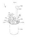
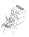
- FIGS. 1A, B, C, D, E and 2A . B . C . D . e . F is a disposable bioreactor 1 or a biotechnological device with a disposable bioreactor, a connection device and a tempering device for use in a in Fig. 3 illustrated parallel bioreactor system 10 for use in cell culture and / or in microbiology.
- This in Fig. 3 shown parallel bioreactor 10 has a base block 11 with four receptacles 12 disposed therein, in each of which a bioreactor 1 can be releasably inserted.
- a temperature control is preferably arranged, which is designed to heat or cool the disposable bioreactors 1 arranged in the receptacles 12 as required. Adjacent to the base block 11, an arrangement with containers 13 is formed. Furthermore, the base block 11 has a stacking surface on which two functional blocks 14, 15 are arranged detachably in a stack formation and designed, for example, as a gas mixing station or pump station are, for example, to supply or remove the necessary for the operation of bioreactors fluids.
- Such a parallel bioreactor system 10 has the advantage of a small footprint and a high scalability, since several of these parallel bioreactor 10, each with four disposable bioreactors 1 can be arranged side by side.
- the disposable bioreactors 1 have the advantage of being able to be used in such a parallel bioreactor system for use in cell culture and / or microbiology as reusable bioreactors.
- the disposable bioreactor 1 has a top plate 100, a dimensionally stable container 200 and a stirrer 300.
- the top plate 100 and the container 200 include a reaction space 400.
- the top plate 100 has an inner side 101 facing the reaction space, on which a plurality of dip tubes 110 are arranged, which projects into the reaction space 400.
- On a side facing away from the reaction space 400 outside 102 of the top plate 100 a plurality of terminals 120 are arranged.
- the agitator 300 has a stirring shaft 310 with a rotation axis and a stirring element 320.
- the stirring element 320 is here designed with wings inclined by 45 °, for example as a pitch blade impeller. Alternatively, for example, at least one Rushton impeller can also be used as the stirring element.
- the stirring element 320 is rigidly attached to the agitator shaft 310, so that rotates upon rotation of the agitator shaft 310 to the stirring member 320.
- the top plate 100 and the container 200 are preferably formed of polyamide and non-detachably connected to each other by ultrasonic welding.
- the agitator 300 in particular the tube shaft 310 and / or the stirring element 320, are preferably made of polystyrene. Polystyrene has a lower temperature resistance than polyamide, so that in a hot steam sterilization of the disposable bioreactor 1, the agitator 300 is rendered unusable and thus reuse of the disposable bioreactor 1 is excluded.
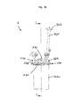
- the agitator shaft 310 is rotatably mounted about the rotation axis in a bearing 500.
- the bearing 500 is arranged in a bulge 130 of the top plate 100.
- a bearing housing 510 delimits a storage space 520 in the reaction space 400.
- the bearing housing 510 is sealed against the agitator shaft 310 via a plain bearing bushing 530.
- the entire bearing housing may be made of a material suitable for sliding bearing. This has the advantage of an item reduction and a high degree of integration, which also has an advantageous effect in the production and assembly.
- the bearing 500 is designed as a roller bearing and preferably has a polymer ball bearing 501 with a cage made of polyethylene, polypropylene, polyvinylidene fluoride, polyetheretherketone or polytetrafluoroethylene and glass beads 502 on.
- the stirring shaft 310 has a magnetic portion 311, 311 ', which is magnetically coupled in an axial direction with a rotary drive 600.
- the magnetic section 311, 311 'of the stirrer shaft 310 is magnetically coupled to the front side, ie in the axial direction, with a rotary drive 600.
- the rotary drive 600 has a substantially cylindrical shape and has a cross-sectional area which substantially corresponds to the cross-sectional area of the bulge 130 on the top plate 100.
- a driving member 613 drives a magnetic driving portion 611; 611 'on.
- axial magnetic coupling has the advantage of a particularly small footprint for the drive on the top plate.
- a magnetic section 311 is arranged at the end of the agitator shaft 310, in which magnets 312 are arranged, preferably in an annular arrangement.
- the magnetic section 311 with the magnets 312 arranged therein is connected in a torsionally rigid manner to the stirrer shaft 310 via a hexagonal nut 313.
- Magnets may also be arranged in the magnetic drive section 611 of the rotary drive, the arrangement of which is preferably aligned with the arrangement of the magnets 312 of the magnetic section 311 of the stirring shaft 310.
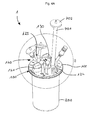
- the magnetic portion 311 ' has a cross section in a plane orthogonal to the agitator shaft 31, and has a magnetic force for magnetic coupling in the axial direction with a rotary drive 600 over most of this cross section, preferably over the entire cross section.
- the cross section of the magnetic portion 311 'with magnetic force effect is preferably circular here and preferably has segments 315a, b of different polarity, which form, for example, a star-shaped pattern or a pattern with pie-shaped segments.
- the magnetic drive section 611 'of the rotary drive 600 has a cross-section in a plane orthogonal to a rotation axis, and has over the majority of this cross section, preferably over the entire cross section, a magnetic force action for a magnetic coupling in the axial direction with the magnetic portion 311 'of the agitator shaft 310 on.
- the cross-section of the magnetic drive force magnetic drive section 611 ' is here preferably circular and preferably has segments 615 of different polarity, which for example form a star-shaped pattern or a pattern with pie-shaped segments.
- the pattern of the segments 615 of the magnetic drive section 611 ' is preferably matched to the pattern of the segments 315a, b of the magnetic section 311' of the stirring shaft 310.
- the magnetic portion 311 'and / or the magnetic drive portion 611' is or are preferably made of a composite or two-component material, in particular a magnet-polymer mixture, and further preferably produced by injection molding.
- the magnetic section 311 'and / or the magnetic drive section 611' can be configured as separate parts which are arranged on the agitator shaft 310 or the drive element 613 and are fastened there, possibly releasably.
- an integral formation of the magnetic portion 311 'with the agitator shaft 310 preferably by spraying a composite or two-component material, in particular a magnet-polymer mixture, on one end of the agitator shaft 310.
- a composite or two-component material in particular a magnet-polymer mixture
- a one-piece design of the magnetic drive section 611 'with a drive element 613 preferably by spraying a composite or two-component material, in particular a magnet-polymer mixture, onto the drive element 613.
- top plate 100 is preferably formed in one piece and made by injection molding of preferably polyamide including arranged on the outside of ports 120 and the inside arranged dip tubes 110.
- the dip tubes 110 correspond to a portion of the terminals 120, so through the corresponding terminals 120 instruments, Sensors, lines, such as hoses through the dip tubes 110 in the reaction chamber on or can be performed.
- the connections 120 are used to provide the substances necessary for the reaction process and / or to remove substances from the reaction space 400, for example gases produced during operation.
- the ports 120 may also be referred to as overlays and the dip tubes 110 as submersibles.
- connection 123 serves, for example, to be connected to an exhaust gas hose 701, at the end of which an exhaust gas sterile filter 702 is again arranged.
- a discharged through the exhaust hose 701 gas stream can be treated, for example, by another device, preferably tempered.
- the sterile filter 702 serves to filter the exhaust gas before it exits.
- a connection slot 124 is formed by two U-shaped profiles, which are particularly suitable for receiving an exhaust gas cooling element 700.
- the exhaust gas cooling element 700 may in particular be designed as a tempering element, as described in the applicant's copending application of the same date entitled "Device for a sterile disposable fluid line of a disposable bioreactor and method for treating a fluid flow".
- Such a cooling element 700 serves to cool the exhaust gas in the tube 701 and condense liquid entrained therein, which then, preferably by gravity, can be returned to the reaction space 400 and thus again on the one hand in the reaction space available and on the other hand, the sterile filter 702 not clogged.
- the terminals 120 may be formed, for example, as screw connections 121 with an internal thread, as clamping type connections 122 or as conical connections 125.
- Unused ports 120 may be sealed for use, such as for the two screw ports 121 in FIG Fig. 1A and 4A, B is shown.
- Fig. 5A, B, C three lying between the two screw terminals 121 conical terminals 125 to recognize where in the Fig. 4A .
- B Hoses are attached. In the in Fig.
- the rear of the two screw terminals 121 ' is closed with a cap, whereas the front of the two screw terminals 121 carries a functional element.
- a functional element for example, pH or DO (Dissolved Oxygen), temperature or other sensors can be arranged on the connections 120 and preferably introduced into the reaction space via the dip tubes 110.
- the two screw terminals 121 are preferably formed as a PG 13.5 thread.
- a particularly preferred combination of ports 120 of a top plate 100 includes two screw ports formed as PG 13.5 threads, gas ports for headspace and sub-water (or sub-media) gas supply, an exhaust port and a connector for exhaust gas cooling Sampling connection with a sampling valve, such as a swabable valve, a fluid port, two dip tubes, a resistance temperature detector (T or RTD) port, and a dissolved oxygen (DO) sensor port with a permeable membrane.
- a sampling valve such as a swabable valve
- a fluid port such as a swabable valve
- T or RTD resistance temperature detector
- DO dissolved oxygen
- Hoses and fittings used with the disposable bioreactor 1 which may come into contact with reaction media are preferably formed from materials certified to United States Pharmacopeia (USP) Class VI, such as polystyrene, polycarbonate, polyamide or silicone.
- USP United States Pharmacopeia
- the hoses to be used are preferably flexible hoses made of thermoplastic elastomers.
Landscapes
- Health & Medical Sciences (AREA)
- Wood Science & Technology (AREA)
- Organic Chemistry (AREA)
- Life Sciences & Earth Sciences (AREA)
- Engineering & Computer Science (AREA)
- Bioinformatics & Cheminformatics (AREA)
- Chemical & Material Sciences (AREA)
- Zoology (AREA)
- Biomedical Technology (AREA)
- Sustainable Development (AREA)
- Microbiology (AREA)
- Biotechnology (AREA)
- Biochemistry (AREA)
- General Engineering & Computer Science (AREA)
- General Health & Medical Sciences (AREA)
- Genetics & Genomics (AREA)
- Clinical Laboratory Science (AREA)
- Apparatus Associated With Microorganisms And Enzymes (AREA)
- Mixers With Rotating Receptacles And Mixers With Vibration Mechanisms (AREA)
- Mixers Of The Rotary Stirring Type (AREA)
- Accessories For Mixers (AREA)
Abstract
Description
Die Erfindung betrifft einen Einwegbioreaktor, insbesondere zur Verwendung in einem, vorzugsweise parallelen, Bioreaktorsystem, für die Anwendung in der Zellkultur und/oder der Mikrobiologie, umfassend eine Kopfplatte, einen formstabilen Behälter und ein Rührwerk, wobei die Kopfplatte und der Behälter einen Reaktionsraum einschließen, die Kopfplatte eine dem Reaktionsraum zugewandte Innenseite und eine Reaktionsraum abgewandte Außenseite mit mehreren Anschlüssen aufweist, und das Rührwerk eine Rührwelle und ein Rührelement aufweist, wobei die Rührwelle in einem Lager um eine Rotationsachse drehbar gelagert ist und das Rührelement an der Rührwelle drehsteif befestigt ist.The invention relates to a disposable bioreactor, in particular for use in a preferably parallel bioreactor system, for use in cell culture and / or microbiology, comprising a top plate, a dimensionally stable container and an agitator, the top plate and the container enclosing a reaction space, the top plate has an inner side facing the reaction space and an outer side facing away from the reaction space with a plurality of connections, and the agitator has a stirring shaft and a stirring element, wherein the stirring shaft is rotatably mounted in a bearing about an axis of rotation and the stirring element is attached to the stirring shaft in a torsionally rigid manner.
Die Erfindung betrifft ferner eine Kopfplatte für einen Einwegbioreaktor, insbesondere zur Verwendung in einem, vorzugsweise parallelen, Bioreaktorsystem, für die Anwendung in der Zellkultur und/oder der Mikrobiologie.The invention further relates to a head plate for a disposable bioreactor, in particular for use in a, preferably parallel, bioreactor system, for use in cell culture and / or microbiology.
Die Erfindung betrifft ferner ein Verfahren zum Herstellen eines Einwegbioreaktors, insbesondere zur Verwendung in einem, vorzugsweise parallelen, Bioreaktorsystem, für die Anwendung in der Zellkultur und/oder der Mikrobiologie sowie ein Verfahren zum Herstellen einer Kopfplatte für einen Einwegbioreaktor, insbesondere zur Verwendung in einem, vorzugsweise parallelen, Bioreaktorsystem, für die Anwendung in der Zellkultur und/oder der Mikrobiologie.The invention further relates to a method for producing a disposable bioreactor, in particular for use in a, preferably parallel, bioreactor system, for use in cell culture and / or microbiology and a method for producing a head plate for a disposable bioreactor, in particular for use in a, preferably parallel, bioreactor system, for use in cell culture and / or microbiology.
Bioreaktoren, die häufig auch als Fermenter bezeichnet werden, schließen einen Reaktionsraum ein, in dem biologische bzw. biotechnologische Prozesse im Labormaßstab durchgeführt werden können. Zu solchen Prozessen zählt beispielsweise die Kultivierung von Zellen, Mikroorganismen oder kleinen Pflanzen unter definierten, vorzugsweise optimierten, kontrollierten und reproduzierbaren Bedingungen. Bioreaktoren verfügen dazu meist über mehrere Anschlüsse, über die Primär- und Sekundärstoffe sowie verschiedene Instrumente, wie beispielsweise Sensoren, in den Reaktionsraum eingebracht werden können oder über die beispielsweise Fluidleitungen, insbesondere Gasleitungen, wie Begasungs- oder Abgasleitungen, angeschlossen werden können. Bioreaktoren weisen ferner in der Regel ein Rührwerk auf, dessen Rührwelle von einem Antrieb in Rotation versetzt werden kann, wodurch ein drehsteif mit der Rührwelle verbundenes Rührelement ebenfalls in Rotation versetzt wird und so eine Durchmischung der im Reaktionsraum vorhandenen Stoffe bewirkt. Es können auch zwei oder mehr Rührelemente, meist axial beabstandet, auf der Rührwelle angeordnet und mit dieser verbunden sein. Das Rührelement bzw. die Rührelemente kann bzw. können auch einstückig mit der Rührwelle ausgebildet sein.Bioreactors, often referred to as fermenters, include a reaction space in which biological or biotechnological processes can be performed on a laboratory scale. Such processes include, for example, the cultivation of cells, microorganisms or small plants under defined, preferably optimized, controlled and reproducible conditions. For this purpose, bioreactors generally have several connections via which primary and secondary substances as well as various instruments, such as sensors, can be introduced into the reaction space or via which, for example, fluid lines, in particular gas lines, such as gassing or exhaust lines, can be connected. Bioreactors also generally have an agitator, the agitator shaft can be rotated by a drive, whereby a stirrer rigidly connected to the agitator shaft is also set in rotation and thus causes a mixing of the substances present in the reaction space. It is also possible for two or more stirring elements, usually axially spaced, to be arranged on the stirring shaft and to be connected to it. The stirring element or the stirring elements can also be formed in one piece with the stirring shaft.
Sowohl für den Anwendungsbereich der Zellkultivierung als auch für den mikrobiologischen Anwendungsbereich ist die Verwendung von Bioreaktoren in, vorzugsweise parallelen, Bioreaktorsystemen bevorzugt. Parallele Bioreaktorsysteme sind beispielsweise in der
Im Anwendungsbereich der Zellkultur werden solche parallelen Bioreaktorsysteme beispielsweise für auf statistischen Planungsmethoden (Design of Experiments DoE) basierenden Versuchsreihen zur Prozessoptimierung, die Prozessentwicklung sowie die Forschung und Entwicklung eingesetzt, beispielsweise um verschiedene Zelllinien, wie Chinese Hamster Ovary (CHO)-, Hybridoma- oder NSO-Zelllinien, zu kultivieren. Unter dem Begriff "Zellkultur" wird im Rahmen des vorliegenden Textes insbesondere die Kultivierung tierischer oder pflanzlicher Zellen in einem Nährmedium außerhalb des Organismus verstanden.In the field of application of cell culture, such parallel bioreactor systems are used, for example, for experimental optimization, process development and research and development based on statistical planning methods (Design of Experiments DoE), for example various cell lines, such as Chinese hamster ovary (CHO), hybridoma or NSO cell lines to cultivate. The term "cell culture" in the context of the present text, in particular the Cultivation of animal or plant cells understood in a nutrient medium outside the organism.
Im Anwendungsbereich der Mikrobiologie werden parallele Bioreaktorsysteme ebenfalls für auf statistischen Planungsmethoden (Design of Experiments DoE) basierenden Versuchsreihen zur Prozessoptimierung, die Prozessentwicklung sowie die Forschung und Entwicklung eingesetzt, beispielsweise um verschiedene Mikroorganismen, insbesondere Bakterien oder Pilze, z.B. Hefen, zu kultivieren.Within the scope of microbiology, parallel bioreactor systems are also used for design optimization experiments, process development and research and development based on statistical design methods (Design of Experiments DoE), for example to detect various microorganisms, particularly bacteria or fungi, e.g. Yeasts, to cultivate.
Aufgrund von meist begrenztem Platz im Labor werden dabei geringe Platzanforderungen, insbesondere geringe Stellplatzanforderungen sowohl für Bioreaktorsysteme als auch für Bioreaktoren selbst angestrebt.Due to the usually limited space in the laboratory small space requirements, especially low space requirements for both bioreactor systems and bioreactors themselves are sought.
Bioreaktoren im Laboreinsatz sind oft aus Glas und/oder Metall, insbesondere rostfreiem Stahl, ausgebildet, da die Bioreaktoren zwischen verschiedenen Anwendungen sterilisiert werden müssen, was vorzugsweise durch eine Heißdampfsterilisation in einem Autoklaven erfolgt. Die Sterilisierung und Reinigung wieder verwendbarer Bioreaktoren ist aufwändig: Der Sterilisations- und Reinigungsprozess kann einer Validierung unterliegen und seine Durchführung für jeden einzelnen Bioreaktor genau dokumentiert werden. Rückstände in einem nicht vollständig sterilisierten Bioreaktor können die Ergebnisse eines nachfolgenden Prozesses verfälschen oder unbrauchbar machen und einen nachfolgenden Prozessablauf stören. Des Weiteren können einzelne Bestandteile bzw. Materialien der Bioreaktoren durch den Sterilisationsprozess beansprucht und z.T. beschädigt werden.Laboratory bioreactors are often constructed of glass and / or metal, particularly stainless steel, because the bioreactors must be sterilized between different applications, preferably by autoclaving superheated steam. The sterilization and cleaning of reusable bioreactors is laborious: the sterilization and purification process may be subject to validation and its implementation accurately documented for each bioreactor. Residues in an incompletely sterilized bioreactor can falsify or render useless the results of a subsequent process and interfere with a subsequent process. Furthermore, individual components or materials of the bioreactors can be claimed by the sterilization process and z.T. to be damaged.
Eine Alternative zu wieder verwendbaren Bioreaktoren stellen Einwegbioreaktoren dar, die für die Durchführung lediglich eines biologischen bzw. biotechnologischen Prozesses verwendet und anschließend entsorgt werden. Durch die Bereitstellung eines neuen, vorzugsweise im Herstellungsprozess sterilisierten, Einwegbioreaktors für jeden Prozess kann die Gefahr einer (Kreuz-)Kontamination reduziert werden und gleichzeitig entfällt der Aufwand der Durchführung und Dokumentation einer einwandfreien Reinigung und Sterilisierung eines zuvor genutzten Bioreaktors. Einwegbioreaktoren sind oft als flexible Behälter ausgebildet, beispielsweise als Beutel oder als Behälter mit zumindest abschnittsweise flexiblen Wänden. Beispiele für solche Bioreaktoren sind in
Ferner sind aus Gründen der Übertragbarkeit von Prozessen auf andere Maßstäbe unter anderem auch qualitativ vergleichbare und insbesondere definierte Strömungsverhältnisse (insbesondere bei der Durchmischung) im Kultivierungsraum wichtig. Diese Anforderung kann bei Bioreaktoren mit flexiblen Wänden nicht bzw. nur mit aufwändigen Zusatzmaßnahmen gewährleistet werden.Furthermore, for reasons of the transferability of processes to other scales, inter alia qualitatively comparable and in particular defined flow conditions (in particular in the case of mixing) in the cultivation space are important. This requirement can not be guaranteed with bioreactors with flexible walls or only with expensive additional measures.
Formstabile Einwegreaktoren sind beispielsweise aus der
Es ist daher eine Aufgabe der vorliegenden Erfindung, einen verbesserten Einwegbioreaktor sowie eine Kopfplatte bereitzustellen und Herstellungsverfahren anzugeben, die einen oder mehrere der genannten Nachteile verringern oder beseitigen. Es ist insbesondere eine Aufgabe der vorliegenden Erfindung, einen verbesserten Einwegbioreaktor bereitzustellen, der für die Anwendung sowohl in der Zellkultur als auch in der Mikrobiologie geeignet ist insbesondere zur Verwendung in einem, vorzugsweise parallelen, Bioreaktorsystem. Eine weitere Aufgabe der Erfindung ist es, einen Einwegbioreaktor und eine Kopfplatte bereitzustellen, die kostengünstig herzustellen sind sowie einfache und kostengünstige Herstellungsverfahren für einen Einwegbioreaktor und eine Kopfplatte anzugeben.It is therefore an object of the present invention to provide an improved disposable bioreactor and a head plate and to provide manufacturing methods that reduce or eliminate one or more of the mentioned disadvantages. It is a particular object of the present invention to provide an improved disposable bioreactor suitable for use in both cell culture and microbiology, particularly for use in a, preferably parallel, bioreactor system. Another object of the invention is to provide a disposable bioreactor and a head plate that are inexpensive to manufacture and to provide simple and inexpensive methods of manufacturing a disposable bioreactor and a head plate.
Gemäß einem ersten Aspekt der Erfindung wird diese Aufgabe gelöst durch einen Einwegbioreaktor nach Anspruch 1: Dieser Einwegbioreaktor der eingangs genannten Art ist dadurch gekennzeichnet, dass das Rührwerk und das Lager vollständig in dem Reaktionsraum angeordnet sind und die Rührwelle einen magnetischen Abschnitt aufweist, der derart angeordnet und ausgebildet ist, dass er in einer axialen Richtung mit einem Rotationsantrieb magnetisch koppelbar ist.According to a first aspect of the invention, this object is achieved by a disposable bioreactor according to claim 1: This disposable bioreactor of the type mentioned above is characterized in that the agitator and the bearing are arranged completely in the reaction space and the agitator shaft has a magnetic portion arranged in such a way and is configured to be magnetically coupled in an axial direction with a rotary drive.
Dieser Einwegbioreaktor zeichnet sich unter anderem dadurch aus, dass das Rührwerk durch einen Magnetantrieb in Rotation versetzt werden kann. Ein Vorteil dieser Ausbildung liegt darin, dass sowohl das Rührwerk als auch das Lager vollständig in dem Reaktionsraum angeordnet sind, d.h. dass keine Durchführung der Rührwelle durch die Kopfplatte erforderlich ist. Auf diese Weise ist auch keine Abdichtung einer solchen Durchführung der Rührwelle durch die Kopfplatte erforderlich. Dies hat den Vorteil, dass die Sterilität des Reaktionsraums nicht durch eine unzureichende Abdichtung einer Durchführung in der Kopfplatte beeinträchtigt werden kann. Ein weiterer Vorteil ist, dass die bei Konstruktionen mit abgedichteter Durchführung auftretenden Reibungswiderstände, die unter anderem zu einer Beschädigung von Septumkomponenten führen können, vollständig vermieden werden.This one-way bioreactor is characterized, inter alia, by the fact that the agitator can be set in rotation by a magnetic drive. An advantage of this design is that both the agitator and the bearing are completely located in the reaction space, i. that no implementation of the stirring shaft by the top plate is required. In this way, no sealing of such a passage of the agitator shaft through the top plate is required. This has the advantage that the sterility of the reaction space can not be affected by insufficient sealing of a passage in the top plate. A further advantage is that the frictional resistances which occur in constructions with a sealed passage, which among other things can lead to damage of septum components, are completely avoided.
Ferner ist vorgesehen, dass eine Kopplung zwischen einem magnetischen Abschnitt der Rührwelle und einem außerhalb des Reaktionsraums an der Außenseite der Kopfplatte angeordneten Antrieb über eine Magnetkopplung in axialer Richtung, d.h. in Richtung der Rotationsachse oder parallel dazu, erfolgt. Zwischen einem magnetischen Abschnitt der Rührwelle und einem magnetischen Antriebsabschnitt des Rotationsantriebs ist vorzugsweise ein minimaler Luftspalt ausgebildet. Eine solche stirnseitige magnetische Kopplung zwischen Rührwelle und Rotationsantrieb hat gegenüber einer Kopplung in radialer Richtung, bei der ein magnetischer Abschnitt des Rotationsantriebs außenumfänglich um einen magnetischen Abschnitt an der Rührwelle angeordnet und beispielsweise in der
Zur Aufnahme des magnetischen Abschnitts der Rührwelle kann die Kopfplatte beispielsweise eine Ausbuchtung aufweisen, die beispielsweise einen kreisförmigen Querschnitt haben kann und die beispielsweise ein außerhalb des Reaktionsraums angeordneter Rotationsantrieb mit einem Ring umgreifen kann, um den Rotationsantrieb konzentrisch über der Ausbuchtung und dem darin vorzugsweise ebenfalls konzentrisch angeordneten magnetischen Abschnitt der Rührwelle anzuordnen. Der magnetische Abschnitt der Rührwelle ist vorzugsweise an einem Ende der Rührwelle angeordnet ist und weist vorzugsweise einen größeren Durchmesser bzw. einen größeren Umfang auf als ein übriger Abschnitt der Rührwelle.To accommodate the magnetic portion of the agitator shaft, the top plate may, for example, have a bulge, which may, for example, have a circular cross-section and which can, for example, surround a rotary drive arranged outside the reaction space with a ring around the rotary drive concentrically over the bulge and also preferably concentrically therein to arrange arranged magnetic portion of the stirring shaft. The magnetic portion of the stirring shaft is preferably disposed at one end of the stirring shaft and preferably has a larger diameter or a larger circumference than a remaining portion of the stirring shaft.
In einer bevorzugten Ausführungsform ist der magnetische Abschnitt einstückig mit der Rührwelle ausgebildet. Dies hat den Vorteil, dass die Anzahl an Teilen im Reaktionsraum reduziert wird und damit auch mögliche Spalte und Toträume zwischen verschiedenen Teilen reduziert werden.In a preferred embodiment, the magnetic portion is formed integrally with the agitator shaft. This has the advantage that the number of parts in the reaction space is reduced and thus also possible gaps and dead spaces between different parts are reduced.
Besonders bevorzugt ist es, dass der magnetische Abschnitt aus einem Kompositwerkstoff mit einer Kunststoffmatrix und einem magnetischen Material besteht oder einen solchen Kompositwerkstoff aufweist. Die hat den Vorteil, dass eine Materialkombination gewählt werden kann, die den Anforderungen der United States Pharmacopeia (USP) Klasse VI entspricht, beispielsweise durch Auswahl eines entsprechend klassifizierten Kunststoffes als Matrix.It is particularly preferred that the magnetic portion consists of a composite material with a plastic matrix and a magnetic material or has such a composite material. This has the advantage that a combination of materials can be chosen that meets the requirements of the United States Pharmacopeia (USP) Class VI, for example, by selecting a correspondingly classified plastic as a matrix.
Ferner ist bevorzugt, dass der magnetische Abschnitt durch Aufspritzen des Zweikomponentenwerkstoffs mit einer Magnetkomponente auf die Rührwelle hergestellt ist.Further, it is preferable that the magnetic portion is made by spraying the two-component material with a magnetic component on the stirring shaft.
Durch Aufspritzen eines solchen Kunststoff-Magnet-Gemischs als Kompositwerkstoff, vorzugsweise im Spritzgießverfahren, auf ein Ende der Rührwelle kann eine besonders einfache und günstige Herstellung der Rührwelle mit stirnseitigem Magnetkopplungsabschnitt erzielt werden, die durch die einstückige Ausbildung gleichzeitig die Anzahl der Teile im Reaktionsraum reduziert.By spraying such a plastic-magnetic mixture as a composite material, preferably by injection molding, on one end of the agitator shaft, a particularly simple and inexpensive production of the stirring shaft can be achieved with frontal magnetic coupling section, which simultaneously reduces the number of parts in the reaction chamber by the one-piece design.
In einer besonders bevorzugten Ausführungsform weist der magnetische Abschnitt einen Querschnitt in einer Ebene orthogonal zur Rührwelle auf, und weist über den Großteil dieses Querschnitts, vorzugsweise über den gesamten Querschnitt, eine magnetische Kraftwirkung für eine magnetische Kopplung in axialer Richtung mit einem Rotationsantrieb auf.In a particularly preferred embodiment, the magnetic portion has a cross-section in a plane orthogonal to the stirring shaft, and has over the majority of this cross section, preferably over the entire cross section, a magnetic force effect for a magnetic coupling in the axial direction with a rotary drive.
Eine solche Ausgestaltung eines vorzugsweise flächigen, zusammenhängenden Querschnitts des Bereichs mit magnetischer Kraftwirkung kann insbesondere durch Spritzgießen eines Kompositwerkstoffs mit einer Kunststoffmatrix und einem magnetischen Material in einer Spritzgießform erzielt werden, die ihrerseits einen Magneten aufweist, um das magnetischen Material des Kompositwerkstoffs beim Spritzgießen auszurichten. Der Querschnitt des magnetischen Abschnitts mit magnetischer Kraftwirkung ist vorzugsweise kreisförmig, ellipsenförmig oder rechteckig. Innerhalb dieses Querschnitts des magnetischen Abschnitts mit magnetischer Kraftwirkung sind vorzugsweise Segmente unterschiedlicher Polung ausgebildet. Beispielsweise können die Segmente ein sternförmiges Muster oder ein Muster mit tortenstückförmigen Segmenten bilden.Such a configuration of a preferably flat, contiguous cross section of the area with magnetic force effect can be achieved in particular by injection molding a composite material with a plastic matrix and a magnetic material in an injection mold, which in turn has a magnet to align the magnetic material of the composite material during injection molding. The cross section of the magnetic portion having magnetic force is preferably circular, elliptical or rectangular. Within this cross section of the magnetic portion with magnetic force effect preferably segments of different polarity are formed. For example, the segments may form a star-shaped pattern or a pie-shaped segment pattern.
Eine solche Ausgestaltung hat mehrere Vorteile: Zum einen kann gegenüber einer Ausbildung mit mehreren, ringförmig angeordneten Stabmagneten ein höheres Drehmoment übertragen werden, was insbesondere erforderlich ist zur Erzielung hoher Drehzahlen von über 1500 rpm, insbesondere bis zu 2000 rpm, bis zu 3000 rpm oder darüber, die insbesondere für Anwendungen in der Mikrobiologie erforderlich sind. Dabei kann gleichzeitig die erforderliche Querschnittsfläche am Ende der Rührwelle und damit der erforderliche Bauraum auf der Kopfplatte gering gehalten werden. Ferner kann durch die Ausbildung von bestimmten Polsegmentmustern eine spezifische Passung von Bioreaktoren zu einem entsprechend ausgebildeten Rotationsantrieb erzielt und damit die Prozesssicherheit erhöht werden, da nur Bioreaktoren mit passender Polsegmentierung von einem Rotationsantrieb angetrieben werden können. Dies ist vorteilhaft, um den Antrieb mit dem gewünschten Drehmoment und der gewünschten Drehzahl sicherzustellen, da Drehmoment und insbesondere erzielte Drehzahl nur bei mechanisch starr an einen Rotationsantrieb gekoppelten Rührwerken überwacht werden, nicht hingegen bei magnetischen Kopplung von Rührwerk und Rotationsantrieb. Eine abweichende Drehzahl bei Verwendung beispielsweise eines Rotationsantriebs mit zu geringer Leistung kann jedoch den Kultivierungsprozess negativ beeinflussen.Such an embodiment has several advantages: Firstly, a higher torque can be transmitted compared to a design with a plurality of annularly arranged bar magnet, which is particularly required to achieve high speeds of over 1500 rpm, in particular up to 2000 rpm, up to 3000 rpm or more , which are particularly required for applications in microbiology. At the same time the required cross-sectional area at the end of the stirring shaft and thus the required space on the top plate can be kept low. Furthermore, by the formation of certain Polsegmentmustern a specific fit of bioreactors can be achieved to a correspondingly designed rotary drive and thus the process reliability can be increased, since only bioreactors with matching Polsegmentierung can be driven by a rotary drive. This is advantageous in order to ensure the drive with the desired torque and the desired speed, since torque and speed achieved in particular are monitored only for mechanically rigidly coupled to a rotary drive agitators, but not for magnetic coupling of agitator and rotary drive. However, a different speed when using, for example, a rotary drive with too low power can adversely affect the cultivation process.
Auch in dieser Ausgestaltung kann der magnetische Abschnitt einstückig mit, vorzugsweise einem Ende, der Rührwelle verbunden sein, beispielsweise durch Aufspritzen des Kompositwerkstoffs auf die Rührwelle. Alternativ kann der magnetische Abschnitt als separates Teil, vorzugsweise im Spritzgussverfahren, ausgebildet und an der Rührwelle angeordnet sein.Also in this embodiment, the magnetic portion may be integral with, preferably one end, of the agitator shaft, for example by spraying the composite material onto the agitator shaft. Alternatively, the magnetic portion may be formed as a separate part, preferably by injection molding, and disposed on the agitator shaft.
Gemäß einem zweiten Aspekt der Erfindung wird die Aufgabe gelöst durch einen Einwegbioreaktor nach Anspruch 4. Gemäß diesem zweiten Aspekt der Erfindung ist ein eingangs genannter Einwegbioreaktor oder ein Einwegbioreaktor gemäß dem ersten Aspekt der Erfindung dadurch gekennzeichnet, dass das Lager als Wälzlager ausgebildet ist.According to a second aspect of the invention, the object is achieved by a disposable bioreactor according to claim 4. According to this second aspect of the invention is a mentioned above disposable bioreactor or a disposable bioreactor according to the first aspect of the invention, characterized in that the bearing is designed as a rolling bearing.
Die in bekannten formstabilen Einwegbioreaktoren für die Anwendung in der Zellkultur eingesetzten Gleitlagerungen haben den Nachteil, dass die Drehzahlen des Rührwerks auf Bereiche von etwa 500 rpm beschränkt sind, da höhere Drehzahlen durch eine starke Reibung der Welle und des Lagers Abwärme erzeugen, die zu einem Schmelzen der Lagerung und damit zu einem Stillstand der Welle führen kann, was den Kultivierungsprozess beenden würde. Eine Gleitlagerung hat den weiteren Nachteil eines erhöhten Material-, insbesondere Kunststoffabriebs, der im Reaktionsraum einen unerwünschten Agglomerationskeim für Zellen darstellen würde und daher beispielsweise in einem Lagergehäuse aufgefangen werden muss.The slide bearings used in known dimensionally stable disposable bioreactors for use in cell culture have the disadvantage that the rotational speeds of the agitator are limited to ranges of about 500 rpm, since higher speeds produce by a strong friction of the shaft and the bearing waste heat, which leads to melting Storage and thus can lead to a standstill of the wave, which would end the cultivation process. A slide bearing has the further disadvantage of increased material, in particular plastic abrasion, which would represent an undesirable agglomeration germ for cells in the reaction space and therefore has to be collected for example in a bearing housing.
Mit der erfindungsgemäßen Ausbildung der Lagerung der Rührwelle als Wälzlager können deutlich höhere Drehzahlen von über 1500 rpm, insbesondere bis zu 2000 rpm, bis zu 3000 rpm oder darüber, realisiert werden, die insbesondere für Anwendungen in der Mikrobiologie erforderlich sind.With the inventive design of the bearing of the stirring shaft as a rolling bearing significantly higher speeds of over 1500 rpm, in particular up to 2000 rpm, up to 3000 rpm or more, can be realized, which are particularly required for applications in microbiology.
Insbesondere ist bevorzugt, dass das Wälzlager ein Polymerkugellager mit Glaskugeln aufweist, wobei das Polymerkugellager vorzugsweise einen Käfig aus einem thermoplastischen Kunststoff aufweist, beispielsweise aus Polyethylen, Polypropylen, Polyvinylidenfluorid, Polyetheretherketon oder Polytetrafluorethylen. Diese Materialpaarung für das Wälzlager hat einerseits den Vorteil, dass die Glaskugeln im Polymerkugellager ruhig und leise laufen und damit die Geräuschbelastung im Labor senken können. Ferner ist die Materialpaarung beständig gegenüber hochmolaren Laugen und Basen, die insbesondere bei mikrobiologischen Anwendungen zum Einsatz kommen und daher entsprechende Anforderungen an die Konstruktion und die eingesetzten Werkstoffe stellen.In particular, it is preferred that the rolling bearing has a polymer ball bearing with glass beads, wherein the polymer ball bearing preferably has a cage made of a thermoplastic material, for example polyethylene, polypropylene, polyvinylidene fluoride, polyetheretherketone or polytetrafluoroethylene. On the one hand, this combination of materials for the rolling bearing has the advantage that the glass spheres in the polymer ball bearing can run quietly and thus reduce the noise level in the laboratory. Furthermore, the material combination is resistant to high molar alkalis and bases, which are used especially in microbiological applications and therefore make appropriate demands on the design and the materials used.
Gemäß einem dritten Aspekt der Erfindung wird die Aufgabe gelöst durch einen Einwegbioreaktor nach Anspruch 5. Gemäß diesem Aspekt ist der eingangs genannte Einwegbioreaktor oder einer der zuvor beschriebenen Einwegbioreaktoren nach dem ersten oder zweiten Aspekt der Erfindung dadurch gekennzeichnet, dass die Kopfplatte und der Behälter unlösbar miteinander verbunden sind, die Kopfplatte aus einem ersten Material und der Behälter aus einem zweiten Material ausgebildet ist und die Rührwelle und/oder das Rührelement aus einem dritten Material ausgebildet ist bzw. sind, wobei das erste Material und das zweite Material eine höhere Temperaturbeständigkeit aufweisen als das dritte Material.According to a third aspect of the invention, the object is achieved by a disposable bioreactor according to claim 5. According to this aspect, the aforementioned one-way bioreactor or one-way bioreactors according to the first or second aspect of the invention characterized in that the top plate and the container are insoluble with each other are connected, the top plate of a first material and the container of a second material is formed and the stirring shaft and / or the stirring element is formed of a third material or, wherein the first Material and the second material have a higher temperature resistance than the third material.
Bei diesem Einwegbioreaktor sind die Kopfplatte und der Behälter unlösbar miteinander verbunden, beispielsweise durch ein stoffschlüssiges Fügeverfahren wie Schweißen. Besonders bevorzugt ist eine Verbindung durch Ultraschallschweißen, da dieses Verfahren eine hohe Prozesssicherheit aufweist und zu einer sehr guten Abdichtung der Verbindung zwischen Kopfplatte und Reaktionsraum und damit zu einer guten Abdichtung des Reaktionsraums gegenüber der Umgebung führt. Ultraschallschweißen ist darüber hinaus ein sehr schnelles Verbindungsverfahren und reduziert den Fertigungsaufwand.In this disposable bioreactor, the top plate and the container are inextricably linked together, for example by a cohesive joining method such as welding. A connection by ultrasonic welding is particularly preferred since this method has a high process reliability and leads to a very good sealing of the connection between top plate and reaction space and thus to a good sealing of the reaction space with respect to the environment. Ultrasonic welding is also a very fast connection process and reduces manufacturing costs.
Eine unlösbare Verbindung von Kopfplatte und Behälter hat den Vorteil, dass nach einer Sterilisation im Herstellungsprozess der Einwegbioreaktor nicht mehr geöffnet werden kann und somit das Risiko einer Kontamination des Reaktionsraums vor der Nutzung des Einwegbioreaktors vermindert werden kann. Ferner hat diese unlösbare Verbindung den Vorteil, dass der Einwegbioreaktor auch nach der Nutzung nicht geöffnet werden kann und seine geschlossene, formstabile Ausbildung beibehält. Dies hat bei der Entsorgung des Einwegbioreaktors gegenüber nicht formstabilen Einwegbioreaktoren den Vorteil, dass eine Dekontaminierung bzw. post-process Sterilisation von möglichen pathogenen Stoffen direkt im Einwegbioreaktor erfolgen kann, ohne dass zusätzliche Behältnisse, wie beispielsweise Verpackungsfolien oder Beutel für eine solche Dekontaminierung erforderlich sind.An inseparable connection of top plate and container has the advantage that after a sterilization in the manufacturing process of the disposable bioreactor can not be opened and thus the risk of contamination of the reaction chamber can be reduced before using the disposable bioreactor. Furthermore, this insoluble compound has the advantage that the disposable bioreactor can not be opened even after use and maintains its closed, dimensionally stable training. This has the advantage in disposing of the disposable bioreactor over non-dimensionally stable disposable bioreactors that decontamination or post-process sterilization of possible pathogenic substances can be done directly in the disposable bioreactor, without additional containers, such as packaging films or bags for such decontamination are required.
Insbesondere im Zusammenhang mit der Dekontaminierung von benutzten Einwegbioreaktoren werden auch die Vorteile der erfindungsgemäßen Materialpaarung deutlich: Die Ausbildung von Kopfplatte und Behälter aus Materialien mit einer Temperaturbeständigkeit, die eine Dekontaminierung erlauben, d.h. die bei einer Dekontaminierung nicht zerstört oder nennenswert angegriffen werden, hat den Vorteil, dass der Einwegbioreaktor beispielsweise mittels Dampfsterilisation dekontaminiert werden kann, ohne dass der Einwegbioreaktor dazu zusätzlich verpackt oder in einem weiteren Behältnis angeordnet werden müsste, da Kopfplatte und Behälter diesem Dekontaminierungsprozess standhalten.In particular in connection with the decontamination of used disposable bioreactors, the advantages of the material pairing according to the invention also become clear: the formation of top plate and container from materials with a temperature resistance which allow decontamination, i. which are not destroyed or significantly attacked in a decontamination, has the advantage that the disposable bioreactor can be decontaminated, for example by steam sterilization, without the disposable bioreactor to be additionally packaged or arranged in another container, as the top plate and container this decontamination process withstand.
Durch die Kombination mit einer Rührwelle und/oder einem Rührelement aus einem Material mit geringerer Temperaturbeständigkeit wird der Vorteil erreicht, dass beim Dekontaminationsprozess die Rührwelle und/oder das Rührelement zerstört oder zumindest funktionsuntüchtig gemacht werden. Das dritte Material weist dazu entsprechende Eigenschaften auf. Insbesondere ist eine Temperaturbeständigkeit des dritten Materials bevorzugt, die einem Dekontaminierungsprozess nicht standhalten.The combination with a stirring shaft and / or a stirring element made of a material with lower temperature resistance provides the advantage that during the decontamination process the stirring shaft and / or the stirring element are destroyed or at least rendered inoperative. The third material has accordingly Properties on. In particular, a temperature resistance of the third material is preferred which does not withstand a decontamination process.
Auf diese Weise kann zuverlässig eine gewollte oder versehentliche Wiederverwendung eines bereits einmal benutzten Einwegbioreaktors verhindert werden, da das Rührwerk nach der Dekontaminierung nicht mehr verwendet werden kann und gleichzeitig durch die unlösbare Verbindung von Kopfplatte und Behälter der Einwegbioreaktor auch nicht geöffnet werden kann, um das Rührwerk auszutauschen.In this way, a deliberate or accidental reuse of a once-used disposable bioreactor can be reliably prevented because the agitator can not be used after decontamination and at the same time can not be opened by the permanent connection of top plate and container of disposable bioreactor to the agitator exchange.
Ferner ist besonders bevorzugt, dass das erste Material der Kopfplatte und das zweite Material des Behälters gleich sind, was insbesondere von Vorteil ist, wenn als Fügeverfahren zum Verbinden von Kopfplatte und Behälter Ultraschallschweißen eingesetzt wird.Furthermore, it is particularly preferred that the first material of the top plate and the second material of the container are the same, which is particularly advantageous when ultrasonic welding is used as the joining method for connecting the top plate and container.
Besonders bevorzugt ist, dass das erste Material und das zweite Material eine höhere Glasübergangstemperatur aufweisen als das dritte Material. Die Glasübergangstemperatur (Tg) ist eine spezifische Materialeigenschaft von Kunststoffen. Sie bezeichnet die Temperatur, bei der amorphe oder teilkristalline Polymere vom festen Zustand in den flüssigen Zustand übergehen, wobei eine deutliche Änderung physikalischer Kenngrößen, z. B. der Härte und der Elastizität eintritt.It is particularly preferred that the first material and the second material have a higher glass transition temperature than the third material. The glass transition temperature (Tg) is a specific material property of plastics. It denotes the temperature at which amorphous or partially crystalline polymers change from the solid state to the liquid state, with a marked change in physical parameters, eg. B. the hardness and elasticity occurs.
Besonders bevorzugt ist, dass das erste Material und das zweite Material eine Glasübergangstemperatur von mindestens 121°C aufweisen und vorzugsweise das dritte Material eine Glasübergangstemperatur von unter 121 °C aufweist. Besonders bevorzugt ist ferner, dass das dritte Material eine Glasübergangstemperatur von über 50°C, insbesondere über 55°C, über 60°C, über 65°C, über 70°C, über 75°C oder über 80°C aufweist. Ferner ist bevorzugt, dass das erste und das zweite Material eine Glasübergangstemperatur von über 125°C, insbesondere über 130°C, über 140°C, über 150°C, über 160°C, über 170°C oder über 180°C aufweisen.It is particularly preferred that the first material and the second material have a glass transition temperature of at least 121 ° C and preferably the third material has a glass transition temperature of less than 121 ° C. It is further particularly preferred that the third material has a glass transition temperature of over 50 ° C, in particular above 55 ° C, above 60 ° C, above 65 ° C, above 70 ° C, above 75 ° C or above 80 ° C. It is further preferred that the first and the second material have a glass transition temperature of over 125 ° C, in particular above 130 ° C, above 140 ° C, above 150 ° C, above 160 ° C, above 170 ° C or above 180 ° C. ,
Die Glasübergangstemperaturen des ersten Materials und des zweiten Materials sind vorzugsweise mindestens 5°C höher, insbesondere mindestens 10°C höher, mindestens 15°C höher, mindestens 20°C höher, mindestens 25°C höher, mindestens 30°C höher, mindestens 25°C höher, mindestens 30°C höher, mindestens 40°C höher, mindestens 50°C höher, mindestens 60°C höher, mindestens 70°C höher oder mindestens 80°C höher als die Glasübergangstemperatur des dritten Materials.The glass transition temperatures of the first material and the second material are preferably at least 5 ° C higher, in particular at least 10 ° C higher, at least 15 ° C higher, at least 20 ° C higher, at least 25 ° C higher, at least 30 ° C higher, at least 25th ° C higher, at least 30 ° C higher, at least 40 ° C higher, at least 50 ° C higher, at least 60 ° C higher, at least 70 ° C higher or at least 80 ° C higher than the glass transition temperature of the third material.
Eine besonders bevorzugte Materialpaarung ergibt sich durch Ausbildung der Kopfplatte und des Behälters aus Polyamid, Polycarbonat, Polymethylpenten oder Polypropylen und Ausbildung des Rührelements und/oder der Rührwelle aus Polystyrol. Diese Materialien weisen Eigenschaften auf, die sie für den Einsatz sowohl in der Zellkultur als auch in der Mikrobiologie geeignet machen. Gleichzeitig unterscheiden sich die für Kopfplatte und Behälter genannten Materialien von dem für das Rührelement und/oder die Rührwelle genannten Material in ihrer Temperaturbeständigkeit derart, dass das Polyamid, Polycarbonat, Polymethylpenten oder Polypropylen einen Dekontaminierungsprozess, insbesondere mittels Dampfsterilisation, im Wesentlichen unbeschadet übersteht, während das Polystyrol bei der Dampfsterilisation zum Schmelzen gebracht wird, sodass die Rührwelle bzw. das Rührelement nicht erneut verwendet werden können.A particularly preferred combination of materials is obtained by forming the top plate and the container of polyamide, polycarbonate, polymethylpentene or polypropylene and forming the stirring element and / or the stirring shaft made of polystyrene. These materials have properties that make them suitable for use in both cell culture and microbiology. At the same time, the materials mentioned for the top plate and the container differ from the material mentioned for the stirring element and / or the stirring shaft in such a way that the polyamide, polycarbonate, polymethylpentene or polypropylene survives a decontamination process, in particular by steam sterilization, essentially without damage Polystyrene is melted in the steam sterilization, so that the stirring shaft or the stirring element can not be used again.
Die bisher beschriebenen Aspekte der Erfindung können einzeln oder in beliebiger Kombination zum Einsatz kommen. Insbesondere können die im Folgenden beschriebenen Weiterbildungen mit Einwegbioreaktoren nach jedem einzelnen der genannten Aspekte oder beliebigen Kombinationen dieser Aspekte kombiniert werden.The aspects of the invention described so far can be used individually or in any combination. In particular, the developments described below can be combined with disposable bioreactors according to each of the mentioned aspects or any combination of these aspects.
Eine bevorzugte Ausführungsform sieht vor, dass die Kopfplatte und der Behälter miteinander verklebt sind. Alternativ ist bevorzugt, dass die Kopfplatte und der Behälter miteinander verschweißt sind, insbesondere mittels Ultraschallschweißen oder Infrarotschweißen. Eine solche unlösbare Verbindung von Kopfplatte und Behälter durch Kleben oder Schweißen verringert die Kontaminationsgefahr durch eine Doppelverwendung oder ein ungewolltes Öffnen des Bioreaktors. Insbesondere das Ultraschallschweißen wird als Herstellungsverfahren bevorzugt, da es eine hohe Prozesssicherheit und damit einhergehende zuverlässige Verbindung von Kopfplatte und Behälter mit einer schnellen und einfachen Herstellung mit reduziertem Fertigungsaufwand verbindet.A preferred embodiment provides that the top plate and the container are glued together. Alternatively, it is preferred that the top plate and the container are welded together, in particular by means of ultrasonic welding or infrared welding. Such a permanent connection of top plate and container by gluing or welding reduces the risk of contamination by a double use or unintentional opening of the bioreactor. In particular, the ultrasonic welding is preferred as a manufacturing method, since it combines high process reliability and associated reliable connection of headstock and container with a quick and easy production with reduced manufacturing costs.
Insbesondere ist bevorzugt, dass die Kopfplatte einstückig ausgebildet ist. Dies reduziert einerseits die Anzahl der Teile im Reaktionsraum, wodurch Toträume und Spalte vermieden werden, und andererseits kann dadurch auf zusätzliche Arbeitsschritte beim Zusammenbau bzw. der Montage des Einwegbioreaktors verzichtet werden. Besonders bevorzugt ist die Herstellung der Kopfplatte im Spritzgussverfahren.In particular, it is preferred that the top plate is formed in one piece. This reduces on the one hand the number of parts in the reaction space, whereby dead spaces and gaps can be avoided, and on the other hand can be dispensed with additional steps in the assembly or assembly of the disposable bioreactor. Particularly preferred is the production of the top plate by injection molding.
Ferner ist die Herstellung der Kopfplatte aus Polyamid, Polycarbonat, Polymethylpenten oder Polypropylen bevorzugt. Diese Werkstoffe haben den Vorteil, einerseits die Anforderungen für einen Einsatz sowohl in der Zellkultur als auch für Anwendungen in der Mikrobiologie zu erfüllen und gleichzeitig eine hohe Temperaturbeständigkeit aufzuweisen.Furthermore, the production of the top plate of polyamide, polycarbonate, polymethylpentene or polypropylene is preferred. These materials have the advantage, on the one hand, of meeting the requirements for use both in cell culture and for applications in microbiology and at the same time having a high temperature resistance.
Eine weitere bevorzugte Ausführungsform des Einwegbioreaktors sieht vor, dass die Kopfplatte auf ihrer Innenseite mehrere Tauchrohre aufweist, die in den Reaktionsraum ragen. Diese Tauchrohre sind vorzugsweise als hohle Hülsen ausgebildet und können verschiedene Instrumente, Sensoren, oder Leitungen, insbesondere Schläuche, aufnehmen. Vorzugsweise korrespondieren die Tauchrohre auf der Innenseite der Kopfplatte mit Anschlüssen auf der Außenseite der Kopfplatte, sodass durch die Anschlüsse und die Tauchrohre Medien oder Elemente in den Reaktionsraum ein- bzw. aus diesem herausgeführt werden können. Vorzugsweise ragen die Tauchrohre, zumindest ein Teil der Tauchrohre, so weit in den Reaktionsraum hinein, dass sie bei einer bestimmungsgemäßen Verwendung des Einwegbioreaktors in einen im Reaktionsraum befindlichen Inhalt, beispielsweise eine Flüssigkeit, eintauchen. Daher die Bezeichnung Tauchrohre. Dies hat den Vorteil, dass auf der Innenseite der Kopfplatte keine weiteren Rohre oder Schläuche angeschlossen werden müssen, sondern die bereits an der Kopfplatte ausgebildeten Tauchrohre, die vorzugsweise einstückig mit der gesamten Kopfplatte ausgebildet sind, verwendet werden können. Dies hat den Vorteil, dass im Herstellungsprozess Montageschritte eingespart werden können und ferner die Anzahl einzelner Baueinheiten, zwischen denen Spalte oder Toträume entstehen können, im Reaktionsraum verringert wird.A further preferred embodiment of the disposable bioreactor provides that the top plate has on its inside a plurality of dip tubes, which protrude into the reaction space. These dip tubes are preferably designed as hollow sleeves and can accommodate various instruments, sensors, or lines, especially hoses. Preferably, the immersion tubes on the inside of the top plate with connections on the outside of the top plate, so that through the connections and the dip tubes media or elements in the reaction space on or can be led out of this. Preferably, the dip tubes, at least a portion of the dip tubes, protrude so far into the reaction space that, when the disposable bioreactor is used as intended, they dip into a content, for example a liquid, present in the reaction space. Hence the term dip tubes. This has the advantage that no further tubes or hoses need to be connected to the inside of the top plate, but the dip tubes already formed on the top plate, which are preferably formed integrally with the entire top plate, can be used. This has the advantage that in the manufacturing process assembly steps can be saved and also reduces the number of individual units between which gaps or dead spaces can be created in the reaction chamber.
Ferner ist eine Ausführung des Einwegbioreaktors bevorzugt, bei dem die Kopfplatte eine Ausbuchtung zur Aufnahme des Lagers aufweist. Eine solche nach außen gerichtete Ausbuchtung der Kopfplatte ist bevorzugt, um das Lager der in dem Reaktionsraum angeordneten Rührwelle aufzunehmen und somit den nutzbaren Reaktionsraum durch die Anordnung des Lagers nur möglichst geringfügig zu verkleinern. Ferner kann an einer solchen Ausbuchtung auf der Außenseite der Kopfplatte einen Rotationsantrieb für das Rührwerk angeordnet werden. Insbesondere ist bevorzugt, dass die Ausbuchtung keine Öffnung in der Kopfplatte aufweist, was insbesondere bei einer Magnetkopplung, insbesondere bei der zuvor beschriebenen stirnseitigen Magnetkopplung, zwischen Rotationsantrieb und Rührwelle bevorzugt ist.Furthermore, an embodiment of the disposable bioreactor is preferred in which the top plate has a recess for receiving the bearing. Such an outwardly directed bulge of the top plate is preferred in order to receive the bearing of the stirring shaft arranged in the reaction space and thus to reduce the usable reaction space by the arrangement of the bearing only as slightly as possible. Furthermore, a rotary drive for the agitator can be arranged on such a bulge on the outside of the top plate. In particular, it is preferred that the bulge has no opening in the top plate, which is particularly preferred in the case of a magnetic coupling, in particular in the case of the previously described frontal magnetic coupling, between the rotary drive and the agitator shaft.
Insbesondere ist bevorzugt, dass der Bioreaktor eine weiter unten beschriebene Kopfplatte oder eine ihrer Fortbildungen aufweist. Zu den besonderen Vorteilen, Ausführungsvarianten und Ausführungsdetails dieser Kopfplatte und ihrer Fortbildungen wird auf unten folgende Beschreibung zu den entsprechenden Merkmalen der Kopfplatte und ihrer Fortbildungen verwiesen.In particular, it is preferred that the bioreactor has a head plate described below or one of its further developments. For the particular advantages, embodiments and details of this top plate and its training is referred to below description of the corresponding features of the top plate and their training.
Ferner ist es bevorzugt, dass der Einwegbioreaktor ein Lagergehäuse aufweist, das einen Lagerraum zur Aufnahme des Lagers innerhalb des Reaktionsraums abgrenzt. Insbesondere in Kombination mit der zuvor beschriebenen Ausbuchtung in der Kopfplatte hat die hier beschriebene Ausführungsform den Vorteil, dass der Lagerraum teilweise, vorzugsweise überwiegend, im Bereich der Ausbuchtung der Kopfplatte angeordnet ist und so ein unterhalb der Kopfplatte angeordneter Teil des Reaktionsraums im Wesentlichen für die bestimmungsgemäße Verwendung des Bioreaktors zur Verfügung steht. Besonders bevorzugt ist es, dass das Lagergehäuse den Lagerraum dichtend gegenüber dem Reaktionsraum abgrenzt, beispielsweise durch eine Gleitlagerbuchse.Furthermore, it is preferred that the disposable bioreactor has a bearing housing which delimits a storage space for receiving the bearing within the reaction space. In particular in combination with the bulge in the top plate described above, the embodiment described here has the advantage that the storage space is partially, preferably predominantly, arranged in the region of the bulge of the top plate and so arranged below the top plate portion of the reaction chamber substantially for the intended Use of the bioreactor is available. It is particularly preferred that the bearing housing delimits the storage space sealingly against the reaction space, for example by a plain bearing bush.
Das Lagergehäuse ist vorzugsweise an der Innenseite der Kopfplatte lösbar befestigt oder unlösbar mit der Innenseite der Kopfplatte verbunden. Eine lösbare Befestigung des Lagergehäuses kann beispielsweise eine Rastverbindung, Clipverbindung oder Verschraubung sein. Eine unlösbare Verbindung des Lagergehäuses mit der Innenseite der Kopfplatte kann beispielsweise durch Kleben oder Schweißen, insbesondere Ultraschallschweißen, hergestellt werden.The bearing housing is preferably releasably attached to the inside of the top plate or permanently connected to the inside of the top plate. A releasable attachment of the bearing housing may be, for example, a latching connection, clip connection or screwing. An undetachable connection of the bearing housing with the inside of the top plate can be produced for example by gluing or welding, in particular ultrasonic welding.
Gemäß einem vierten Aspekt der Erfindung wird die eingangs genannte Aufgabe gelöst durch eine biotechnologische Vorrichtung, umfassend einen zuvor beschriebenen Einwegbioreaktor gemäß seiner verschiedenen Aspekte oder Fortbildungen, und einen Rotationsantrieb mit einem magnetischen Antriebsabschnitt, der derart angeordnet und ausgebildet ist, dass er in einer axialen Richtung mit dem magnetischen Abschnitt der Rührwelle magnetisch koppelbar ist.According to a fourth aspect of the invention, the object mentioned at the outset is achieved by a biotechnological device comprising a disposable bioreactor according to its various aspects or refinements, and a rotary drive having a magnetic drive section arranged and adapted to be in an axial direction is magnetically coupled with the magnetic portion of the stirring shaft.
Vorzugsweise besteht der magnetische Antriebsabschnitt aus einem Kompositwerkstoff mit einer Kunststoffmatrix und einem magnetischen Material oder weist einen solchen Kompositwerkstoff auf.The magnetic drive section preferably consists of a composite material with a plastic matrix and a magnetic material or has such a composite material.
Ferner ist bevorzugt, dass der Komposit- bzw. Zweikomponentenwerkstoff mit einer Magnetkomponente auf ein stirnseitiges Antriebselement des Rotationsantriebs aufgespritzt ist.It is further preferred that the composite or two-component material is sprayed with a magnetic component on a front-side drive element of the rotary drive.
In einer besonders bevorzugten Ausführungsform weist der magnetische Antriebsabschnitt einen Querschnitt in einer Ebene orthogonal zu einer Rotationsachse auf, und weist über den Großteil dieses Querschnitts, vorzugsweise über den gesamten Querschnitt, eine magnetische Kraftwirkung für eine magnetische Kopplung in axialer Richtung mit dem magnetischen Abschnitt der Rührwelle auf.In a particularly preferred embodiment, the magnetic drive section has a cross section in a plane orthogonal to an axis of rotation, and has a magnetic force for a magnetic coupling in the axial direction with the magnetic portion of the agitator shaft over most of this cross section, preferably over the entire cross section on.
Eine solche Ausgestaltung eines vorzugsweise flächigen, zusammenhängenden Querschnitts des Bereichs mit magnetischer Kraftwirkung des Antriebsabschnitts kann insbesondere durch Spritzgießen eines Kompositwerkstoffs mit einer Kunststoffmatrix und einem magnetischen Material in einer Spritzgießform erzielt werden, die ihrerseits einen Magneten aufweist, um das magnetischen Material des Kompositwerkstoffs beim Spritzgießen auszurichten. Der Querschnitt des magnetischen Antriebsabschnitts mit magnetischer Kraftwirkung ist vorzugsweise kreisförmig, ellipsenförmig oder rechteckig. Innerhalb dieses Querschnitts des magnetischen Antriebsabschnitts mit magnetischer Kraftwirkung sind vorzugsweise Segmente unterschiedlicher Polung ausgebildet. Beispielsweise können die Segmente ein sternförmiges Muster oder ein Muster mit tortenstückförmigen Segmenten bilden. Das Muster der Segmente des magnetischen Antriebsabschnitts ist vorzugsweise auf das Muster der Segmente des magnetischen Abschnitts der Rührwelle abgestimmt.Such a configuration of a preferably flat, contiguous cross-section of the area of magnetic force of the drive section can be achieved in particular by injection molding a composite material with a plastic matrix and a magnetic material in an injection mold, which in turn has a magnet to align the magnetic material of the composite material during injection molding , The cross-section of the magnetic drive portion with magnetic force is preferably circular, elliptical or rectangular. Within this cross section of the magnetic drive section with magnetic force action preferably segments of different polarity are formed. For example, the segments may form a star-shaped pattern or a pie-shaped segment pattern. The pattern of the segments of the magnetic drive section is preferably matched to the pattern of the segments of the magnetic section of the stirring shaft.
Eine solche Ausgestaltung hat mehrere Vorteile: Zum einen kann gegenüber einer Ausbildung mit mehreren, ringförmig angeordneten Stabmagneten ein höheres Drehmoment übertragen werden, was insbesondere erforderlich ist zur Erzielung hoher Drehzahlen von über 1500 rpm, insbesondere bis zu 2000 rpm, bis zu 3000 rpm oder darüber, die insbesondere für Anwendungen in der Mikrobiologie erforderlich sind. Dabei kann gleichzeitig die erforderliche Querschnittsfläche des Rotationsantriebs und damit der erforderliche Bauraum auf der Kopfplatte gering gehalten werden. Ferner kann durch die Ausbildung von bestimmten Polsegmentmustern eine spezifische Passung von Bioreaktoren zu einem entsprechend ausgebildeten Rotationsantrieb realisiert und damit die Prozesssicherheit erhöht werden, da nur Bioreaktoren mit passender Polsegmentierung von einem Rotationsantrieb angetrieben werden können. Dies ist vorteilhaft, um den Antrieb mit dem gewünschten Drehmoment und der gewünschten Drehzahl sicherzustellen, da Drehmoment und insbesondere erzielte Drehzahl üblicherweise nicht überwacht werden und eine abweichende Drehzahl bei Verwendung beispielsweise eines Rotationsantriebs mit zu geringer Leistung den Kultivierungsprozess negativ beeinflussen kann.Such an embodiment has several advantages: Firstly, a higher torque can be transmitted compared to a design with a plurality of annularly arranged bar magnet, which is particularly required to achieve high speeds of over 1500 rpm, in particular up to 2000 rpm, up to 3000 rpm or more , which are particularly required for applications in microbiology. At the same time the required cross-sectional area of the rotary drive and thus the required space on the top plate can be kept low. Furthermore, by forming certain pole segment patterns, a specific fit of bioreactors to a correspondingly designed rotary drive can be realized, and thus process reliability can be increased, since only bioreactors with suitable pole segmentation can be driven by a rotary drive. This is advantageous to ensure the drive with the desired torque and the desired speed, since torque and especially achieved speed are usually not monitored and a different speed when using, for example, a rotary drive with too little power can adversely affect the cultivation process.
Zu den Vorteilen, Ausführungsvarianten und Ausführungsdetails dieser biotechnologischen Vorrichtung und ihrer Fortbildungen wird auf die vorangegangene Beschreibung zu den entsprechenden Vorrichtungsmerkmalen des Einweg-Bioreaktors verwiesen.For the advantages, variants and details of execution of this biotechnological device and its training reference is made to the preceding description of the corresponding device features of the disposable bioreactor.
Gemäß einem fünften Aspekt der Erfindung wird die eingangs genannte Aufgabe gelöst durch eine Kopfplatte nach Anspruch 10. Diese Kopfplatte ist insbesondere geeignet für einen zuvor beschriebenen Einwegbioreaktor, seine verschiedenen Aspekte und Fortbildungen. Die Kopfplatte umfasst eine Innenseite und eine der Innenseite gegenüberliegende Außenseite, wobei die Innenseite mehrere Tauchrohre aufweist und die Außenseite mehrere Anschlüsse aufweist, und wobei die Kopfplatte einstückig ausgebildet ist.According to a fifth aspect of the invention, the above-mentioned object is achieved by a head plate according to claim 10. This head plate is particularly suitable for a previously described disposable bioreactor, its various aspects and training. The top plate includes an inner side and an outer side opposite the inner side, wherein the inner side has a plurality of dip tubes and the outer side has a plurality of terminals, and wherein the head plate is integrally formed.
Ein solche einstückige Ausbildung einer Kopfplatte, die gleichzeitig auf ihrer Außenseite mehrere Anschlüsse und auf ihrer Innenseite mehrere Tauchrohre aufweist, hat den Vorteil eines besonders hohen Integrationsgrades. Dadurch wird die Montage eines Einwegbioreaktor deutlich vereinfacht, da die Tauchrohre Leitungen, wie z.B. Schläuche, ersetzen, die bei bekannten Kopfplatten an auf der Innenseite vorhandene Anschlüsse montiert werden müssen. Durch die einstückige Ausbildung wird auch die Anzahl von Teilen im Reaktionsraum und damit die Anzahl von Spalten und Toträumen reduziert.Such a one-piece design of a top plate, which has at the same time on its outside a plurality of terminals and on its inside a plurality of dip tubes, has the advantage of a particularly high degree of integration. This greatly simplifies the assembly of a disposable bioreactor since the dip tubes provide conduits such as e.g. Replace hoses, which must be mounted in known head plates on existing connections on the inside. The one-piece design also reduces the number of parts in the reaction space and thus the number of gaps and dead spaces.
Besonders bevorzugt ist, dass die Tauchrohre eine Länge aufweisen, so dass die Tauchrohre bei einem Mindestfüllvolumen eines Einwegbioreaktors, mit dem die Kopfplatte verwendet wird, in den Inhalt bzw. die Kulturbrühe eintauchen. Insbesondere ist eine Länge der Tauchrohre von mindestens 85 Prozent eines Durchmessers der Kopfplatte bevorzugt. Als Durchmesser ist hier beispielsweise der Durchmesser einer im Querschnitt kreisförmigen Kopfplatte zu verstehen. Bei einer Kopfplatte mit einem elliptischen oder eckigen Querschnitt ist unter Durchmesser eine Ausdehnung der Kopfplatte in einer ihrer beiden Haupterstreckungsrichtungen zu verstehen.It is particularly preferred that the dip tubes have a length such that the dip tubes dive into the content or the culture broth at a minimum filling volume of a disposable bioreactor with which the top plate is used. In particular, a length of the dip tubes of at least 85 percent of a diameter of the top plate is preferred. The diameter is to be understood here as the diameter of a cross-sectionally circular head plate, for example. In the case of a head plate with an elliptical or angular cross section, the term "diameter" is understood to mean an extension of the head plate in one of its two main directions of extension.
Besonders bevorzugt ist eine Länge der Tauchrohre von über 50 Prozent, vorzugsweise mindestens 75 Prozent, mindestens 80 Prozent, mindestens 85 Prozent, mindestens 90 Prozent oder mindestens 95 Prozent des Durchmessers der Kopfplatte. Ferner ist bevorzugt, dass die Länge der Tauchrohre mindestens dem Durchmesser der Kopfplatte entspricht. Ferner ist eine Länge der Tauchrohre bevorzugt, die größer als das 1,1-fache, größer als das 1,2-fache, größer als das 1,3-fache, größer als das 1,4-fache, größer als das 1,5-fache, größer als das 1,6-fache, größer als das 1,7-fache, größer als das 1,8-fache, größer als das 1,9-fache oder größer als das 2-fache des Durchmessers der Kopfplatte ist.Particularly preferred is a length of the dip tubes of over 50 percent, preferably at least 75 percent, at least 80 percent, at least 85 percent, at least 90 percent or at least 95 percent of the diameter of the top plate. Furthermore, it is preferred that the length of the dip tubes corresponds at least to the diameter of the head plate. Further, a length of the dip tubes greater than 1.1 times, greater than 1.2 times, greater than 1.3 times, greater than 1.4 times, greater than 1, is preferred. 5 times, larger than 1.6 times, larger than 1.7 times, larger than 1.8 times, larger than 1.9 times or larger than 2 times the diameter of the top plate is.
Die Kopfplatte weist vorzugsweise mindestens drei, insbesondere mindestens fünf Tauchrohre auf.The top plate preferably has at least three, in particular at least five dip tubes.
Die Tauchrohre weisen vorzugsweise einen Innendurchmesser von weniger als 8 Millimeter, insbesondere weniger als weniger als 7 Millimeter, weniger als 6 Millimeter, weniger als 5 Millimeter, weniger als 4,8 Millimeter, weniger als 4,75 Millimeter, weniger als 4,7 Millimeter, weniger als 4,5 Millimeter, weniger als 4,3 Millimeter, weniger als 4 Millimeter, weniger als 3,5 Millimeter, weniger als 3 Millimeter, weniger als 2,5 Millimeter, weniger als 2 Millimeter, weniger als 1,5 Millimeter oder weniger als 1 Millimeter auf.The dip tubes preferably have an inner diameter of less than 8 millimeters, more preferably less than 7 millimeters, less than 6 millimeters, less than 5 millimeters, less than 4.8 millimeters, less than 4.75 millimeters, less than 4.7 Millimeters, less than 4.5 millimeters, less than 4.3 millimeters, less than 4 millimeters, less than 3.5 millimeters, less than 3 millimeters, less than 2.5 millimeters, less than 2 millimeters, less than 1.5 Millimeters or less than 1 millimeter.
Bevorzugt ist ferner, dass zumindest zwei, vorzugsweise mehrere, der Tauchrohre einer Kopfplatte unterschiedliche Innendurchmesser aufweisen. Bevorzugt ist ferner, dass zumindest zwei, vorzugsweise mehrere, der Tauchrohre einer Kopfplatte unterschiedliche Längen aufweisen. Diese Ausbildungen sind bevorzugt, um die Tauchrohre auf unterschiedliche Verwendungen anzupassen, um einen flexiblen, breiten Einsatzbereich eines Einwegbioreaktors mit einer solchen Kopfplatte zu schaffen.It is further preferred that at least two, preferably several, of the dip tubes of a head plate have different inner diameters. It is further preferred that at least two, preferably more, of the dip tubes of a head plate have different lengths. These designs are preferred to adapt the dip tubes to different uses to provide a flexible, wide range of use of a disposable bioreactor with such a head plate.
Besonders bevorzugt ist, dass die Kopfplatte im Spritzgussverfahren hergestellt ist.It is particularly preferred that the top plate is produced by injection molding.
Vorzugsweise ist die Kopfplatte aus Polyamid, Polycarbonat, Polymethylpenten oder Polypropylen bevorzugt. Diese Werkstoffe haben den Vorteil, einerseits die Anforderungen für einen Einsatz sowohl in der Zellkultur als auch für Anwendungen in der Mikrobiologie zu erfüllen und gleichzeitig eine hohe Temperaturbeständigkeit aufzuweisen.Preferably, the top plate of polyamide, polycarbonate, polymethylpentene or polypropylene is preferred. These materials have the advantage, on the one hand, of meeting the requirements for use both in cell culture and for applications in microbiology and at the same time having a high temperature resistance.
Ferner weist die Kopfplatte vorzugsweise eine Ausbuchtung zur Aufnahme eines Lagers eines Rührwerks auf. Dies ist insbesondere bevorzugt, wenn die Kopfplatte als Kopfplatte eines zuvor beschriebenen Einwegbioreaktors mit einer Magnetkopplung zwischen Rührwerk und Rotationsantrieb verwendet werden soll.Furthermore, the top plate preferably has a recess for receiving a bearing of an agitator. This is particularly preferred when the top plate is to be used as a top plate of a previously described one-way bioreactor with a magnetic coupling between agitator and rotary drive.
Besonders bevorzugt ist, dass sich der Durchmesser von zumindest einem der Tauchrohre an seinem der Kopfplatte abgewandten Ende verjüngt. Vorzugsweise ist dieses sich verjüngende Tauchrohr und/oder eines oder mehrere der anderen Tauchrohre an seinem der Kopfplatte abgewandten Ende verschlossen und ferner vorzugsweise an diesem verschlossenen Ende mit einer Öffnung versehen, wobei diese Öffnung vorzugsweise einen Durchmesser aufweist, der geringer ist als der Innendurchmesser des Tauchrohrs. Dies ist insbesondere bevorzugt, wenn ein solches Tauchrohr als Begasungsrohr eingesetzt werden soll.It is particularly preferred that the diameter of at least one of the dip tubes tapers at its end facing away from the top plate. Preferably, this tapered dip tube and / or one or more of the other dip tubes is closed at its end facing away from the top plate and further preferably provided at this closed end with an opening, said opening preferably has a diameter which is smaller than the inner diameter of the dip tube , This is particularly preferred if such a dip tube is to be used as a gassing tube.
Die Tauchrohre weisen vorzugsweise eine Wandstärke von unter 3 Millimeter auf, insbesondere eine Wandstärke unter 2 Millimeter, unter 1,5 Millimeter oder unter 1 Millimeter.The dip tubes preferably have a wall thickness of less than 3 millimeters, in particular a wall thickness of less than 2 millimeters, less than 1.5 millimeters or less than 1 millimeter.
Zumindest einer, vorzugsweise zwei der Anschlüsse auf der Außenseite der Kopfplatte weisen ein Gewinde auf, vorzugsweise ein Innengewinde. Auf diese Weise können an den Anschlüssen Schraubverbindungen hergestellt werden, ohne dass dafür zunächst weitere Anschlusselemente an der Kopfplatte angebracht werden müssen.At least one, preferably two of the connections on the outside of the top plate have a thread, preferably an internal thread. This way you can the connections screw connections are made without the need for further connection elements must first be attached to the top plate.
Gemäß einem sechsten Aspekt der Erfindung wird die eingangs genannte Aufgabe gelöst durch ein Verfahren zum Herstellen eines Einwegbioreaktors nach Anspruch 12. Gemäß einem siebten Aspekt der Erfindung oder gemäß einer Weiterbildung des vorhergehenden Aspekts wird die eingangs genannte Aufgabe gelöst durch ein Verfahren zum Herstellen eines Einwegbioreaktors nach Anspruch 13. Gemäß einem achten Aspekt der Erfindung wird die eingangs genannte Aufgabe gelöst durch ein Verfahren zum Herstellen einer Kopfplatte für einen Einwegbioreaktor nach Anspruch 14. Zu den Vorteilen, Ausführungsvarianten und Ausführungsdetaüs dieser Verfahrensaspekte der Erfindung und ihrer Fortbildungen wird auf die vorangegangene Beschreibung zu den entsprechenden Vorrichtungsmerkmalen des Einweg-Bioreaktors und der Kopfplatte verwiesen.According to a sixth aspect of the invention, the object mentioned is achieved by a method for producing a disposable bioreactor according to
Einige beispielhafte Ausführungsformen der Erfindung werden im Folgenden anhand der beiliegenden Figuren beschrieben. Es zeigen:
- Fig. 1A:
- eine dreidimensionale Ansicht einer beispielhaften Ausführungsform eines erfindungsgemäßen Einwegbioreaktors;
- Fig. 1B:
- eine Seitenansicht des Einwegbioreaktors gemäß
Fig. 1A ; - Fig. 1C:
- eine Schnittdarstellung des Einwegbioreaktors gemäß
Fig. 1A entlang der Schnittebene A-A inFig. 1C ; - Fig. 1 D:
- einen vergrößerten Ausschnitt aus
Fig. 1C ; - Fig. 1 E:
- eine alternative Ausgestaltung des magnetischen Abschnitts;
- Fig. 2A:
- eine dreidimensionale Ansicht einer biotechnologischen Vorrichtung mit einem Einwegbioreaktor, einer Anschlussvorrichtung und einer Temperiereinrichtung;
- Fig. 2B:
- eine Seitenansicht der biotechnologischen Vorrichtung gemäß
Fig. 2A ; - Fig. 2C:
- eine Draufsicht auf die biotechnologische Vorrichtung gemäß
Fig. 2A ; - Fig. 2D:
- eine Schnittdarstellung der biotechnologischen Vorrichtung gemäß
Fig. 2A entlang der Schnittebene A-A inFig. 2C ; - Fig. 2E:
- einen vergrößerten Ausschnitt aus
Fig. 2D ; - Fig. 2F:
- eine alternative Ausgestaltung des magnetischen Abschnitts der Rührwelle und des magnetischen Rotationsabschnitts des Rotationsantriebs;
- Fig. 3:
- ein paralleles Bioreaktorsystem;
- Fig. 4A:
- den Einwegbioreaktor gemäß
Fig. 1A mit Angabe eines Vergrößerungsausschnitts B; - Fig. 4B:
- den vergrößerten Ausschnitt B aus
Fig. 4A ; ; - Fig. 5A:
- eine dreidimensionale Ansicht einer Kopfplatte;
- Fig. 5B:
- eine Seitenansicht der Kopfplatte gemäß
Fig. 5A ; und - Fig. 5C:
- eine Draufsicht auf die Kopfplatte gemäß
Fig. 5A .
- Fig. 1A:
- a three-dimensional view of an exemplary embodiment of a disposable bioreactor according to the invention;
- 1B:
- a side view of the disposable bioreactor according to
Fig. 1A ; - Fig. 1C:
- a sectional view of the disposable bioreactor according to
Fig. 1A along the cutting plane AA inFig. 1C ; - Fig. 1 D:
- an enlarged section
Fig. 1C ; - Fig. 1 E:
- an alternative embodiment of the magnetic portion;
- Fig. 2A:
- a three-dimensional view of a biotechnological device with a disposable bioreactor, a connection device and a tempering device;
- Fig. 2B:
- a side view of the biotechnological device according to
Fig. 2A ; - Fig. 2C:
- a plan view of the biotechnological device according to
Fig. 2A ; - Fig. 2D:
- a sectional view of the biotechnological device according to
Fig. 2A along the cutting plane AA inFig. 2C ; - Fig. 2E:
- an enlarged section
Fig. 2D ; - Fig. 2F:
- an alternative embodiment of the magnetic portion of the stirring shaft and the magnetic rotary portion of the rotary drive;
- 3:
- a parallel bioreactor system;
- Fig. 4A:
- the disposable bioreactor according to
Fig. 1A indicating an enlargement section B; - 4B:
- the enlarged detail B from
Fig. 4A ; ; - Fig. 5A:
- a three-dimensional view of a head plate;
- Fig. 5B:
- a side view of the top plate according to
Fig. 5A ; and - Fig. 5C:
- a plan view of the top plate according to
Fig. 5A ,
Die
In den
Der Einwegbioreaktor 1 weist eine Kopfplatte 100, einen formstabilen Behälter 200 und ein Rührwerk 300 auf. Die Kopfplatte 100 und der Behälter 200 schließen einen Reaktionsraum 400 ein. Die Kopfplatte 100 hat eine dem Reaktibnsraum zugewandte Innenseite 101, an der mehrere Tauchrohre 110 angeordnet sind, die in den Reaktionsraum 400 ragen. Auf einer dem Reaktionsraum 400 abgewandten Außenseite 102 der Kopfplatte 100 sind mehrere Anschlüsse 120 angeordnet.The
Das Rührwerk 300 weist eine Rührwelle 310 mit einer Rotationsachse und einem Rührelement 320 auf. Das Rührelement 320 ist hier mit um 45° geneigten Flügeln ausgebildet, beispielsweise als Pitch Blade Impeller. Alternativ kann beispielsweise auch mindestens ein Rushton-Impeller als Rührelement eingesetzt werden. Das Rührelement 320 ist drehsteif an der Rührwelle 310 befestigt, sodass bei einer Rotation der Rührwelle 310 auf das Rührelement 320 mitrotiert.The
Die Kopfplatte 100 und der Behälter 200 sind vorzugsweise aus Polyamid ausgebildet und mittels Ultraschallschweißen miteinander unlösbar verbunden. Das Rührwerk 300, insbesondere die Rohrwelle 310 und/oder das Rührelement 320, sind vorzugsweise aus Polystyrol ausgebildet. Polystyrol weist eine geringere Temperaturbeständigkeit auf als Polyamid, sodass bei einer Heißdampfsterilisation des Einwegbioreaktors 1 das Rührwerk 300 unbrauchbar gemacht wird und damit eine Wiederverwendung des Einwegbioreaktors 1 ausgeschlossen ist.The
Die Rührwelle 310 ist um die Rotationsachse drehbar in einem Lager 500 gelagert. Das Lager 500 ist in einer Ausbuchtung 130 der Kopfplatte 100 angeordnet. Ein Lagergehäuse 510 grenzt einen Lagerraum 520 in dem Reaktionsraum 400 ab. Das Lagergehäuse 510 ist über eine Gleitlagerbuchse 530 gegenüber der Rührwelle 310 abgedichtet. Vorzugsweise kann das gesamte Lagergehäuse aus einem Material bestehen, das für eine Gleitlagerung geeignet ist. Dies hat den Vorteil, einer Einzelteilreduktion und eines hohen Integrationsgrades, was sich auch vorteilhaft in der Herstellung und Montage auswirkt. Das Lager 500 ist als Wälzlager ausgebildet und weist vorzugsweise ein Polymerkugellager 501 mit einem Käfig aus Polyethylen, Polypropylen, Polyvinylidenfluorid, Polyetheretherketon oder Polytetrafluorethylen sowie Glaskugeln 502 auf.The
Das Rührwerk 300 und das Lager 500 sind vollständig in dem Reaktionsraum 400 angeordnet. Wie insbesondere in
In der in den
In einer alternativen, besonders bevorzugten Ausführungsform gemäß der
Vorzugsweise weist auch der magnetische Antriebsabschnitt 611' des Rotationsantriebs 600 einen Querschnitt in einer Ebene orthogonal zu einer Rotationsachse auf, und weist über den Großteil dieses Querschnitts, vorzugsweise über den gesamten Querschnitt, eine magnetische Kraftwirkung für eine magnetische Kopplung in axialer Richtung mit dem magnetischen Abschnitt 311' der Rührwelle 310 auf.Preferably, the magnetic drive section 611 'of the
Der Querschnitt des magnetischen Antriebsabschnitts 611' mit magnetischer Kraftwirkung ist hier vorzugsweise kreisförmig ausgebildet und weist vorzugsweise Segmente 615 unterschiedlicher Polung auf, die beispielsweise ein sternförmiges Muster oder ein Muster mit tortenstückförmigen Segmenten bilden. Das Muster der Segmente 615 des magnetischen Antriebsabschnitts 611' ist vorzugsweise auf das Muster der Segmente 315a,b des magnetischen Abschnitts 311' der Rührwelle 310 abgestimmt.The cross-section of the magnetic drive force magnetic drive section 611 'is here preferably circular and preferably has segments 615 of different polarity, which for example form a star-shaped pattern or a pattern with pie-shaped segments. The pattern of the segments 615 of the magnetic drive section 611 'is preferably matched to the pattern of the
Der magnetische Abschnitt 311' und/oder der magnetische Antriebsabschnitt 611' ist bzw. sind vorzugsweise aus einem Komposit- oder Zweikomponenten-Werkstoff, insbesondere einem Magnet-Polymer-Gemisch, ausgebildet und ferner vorzugsweise im Spritzgussverfahren hergestellt. Der magnetischen Abschnitt 311' und/oder der magnetische Antriebsabschnitt 611' kann bzw. können als separate Teile, die an der Rührwelle 310 bzw. dem Antriebselement 613 angeordnet und dort, ggf. lösbar, befestigt werden, ausgebildet sein.The magnetic portion 311 'and / or the magnetic drive portion 611' is or are preferably made of a composite or two-component material, in particular a magnet-polymer mixture, and further preferably produced by injection molding. The magnetic section 311 'and / or the magnetic drive section 611' can be configured as separate parts which are arranged on the
Besonders bevorzugt ist eine einstückige Ausbildung des magnetischen Abschnitts 311' mit der Rührwelle 310, vorzugsweise durch Aufspritzen eines ein Komposit- oder Zweikomponenten-Werkstoffs, insbesondere eines Magnet-Polymer-Gemischs, auf ein Ende der Rührwelle 310. Besonders bevorzugt ist ferner eine einstückige Ausbildung des magnetischen Antriebsabschnitts 611' mit einem Antriebselement 613, vorzugsweise durch Aufspritzen eines ein Komposit- oder Zweikomponenten-Werkstoffs, insbesondere eines Magnet-Polymer-Gemischs, auf das Antriebselement 613.Particularly preferred is an integral formation of the magnetic portion 311 'with the
Die insbesondere in
Der Anschluss 123 dient beispielsweise dazu, mit einen Abgasschlauch 701 verbunden zu werden, an dessen Ende wiederum ein Abgas-Sterilfilter 702 angeordnet ist. Ein durch den Abgasschlauch 701 abgeführte Gasstrom kann beispielsweise durch eine weitere Vorrichtung behandelt, vorzugsweise temperiert, werden. Der Sterilfilter 702 dient dazu, das Abgas vor seinem Austritt zu filtern. Neben dem Anschluss 123 für einen Abgasschlauch 701 ist ein Anschlussschlitz 124 durch zwei U-förmige Profile gebildet, die insbesondere dafür geeignet sind, ein Abgaskühlelement 700 aufzunehmen. Das Abgaskühlelement 700 kann insbesondere als Temperierelement ausgebildet sein, wie es in der parallelen Anmeldung der Anmelderin vom selben Tage mit dem Titel "Vorrichtung für eine sterile Einweg-Fluidleitung eines Einwegbioreaktors und Verfahren zum Behandeln eines Fluidstroms" beschrieben ist. Ein solches Kühlelement 700 dient dazu, das Abgas im Schlauch 701 zu kühlen und darin mitgeführte Flüssigkeit zu kondensieren, die dann, vorzugsweise durch Gravitation, in den Reaktionsraum 400 zurückgeführt werden kann und damit einerseits im Reaktionsraum wieder zur Verfügung steht und andererseits den Sterilfilter 702 nicht verstopft.The
Die Anschlüsse 120 können beispielsweise als Schraubanschlüsse 121 mit einem Innengewinde, als Klemmartschlüsse 122 oder als kegelförmige Anschlüsse 125 ausgebildet sein. Die in
Eine besonders bevorzugte Kombination von Anschlüssen 120 einer Kopfplatte 100 beinhaltet zwei als PG 13,5 Gewinde ausgebildete Schraubanschlüsse, Gasanschlüsse für Kopfraum- und Unter-Wasser-(bzw. Unter-Medien-)Gaszufuhr, einen Abgasanschluss sowie eine Steckverbindung für eine Abgaskühlung, einen Beprobungsanschluss mit einem Beprobungsventil, beispielsweise einem swabable valve, einen Medienanschluss, zwei Tauchrohre, einen Anschluss für einen Widerstandstemperaturfühler (resistance temperature detector (T oder RTD)) und einen Gelöstsauerstoff(DO)-Sensoranschluss mit einer permeablen Membran. Eine besonders bevorzugte Kombination von Anschlüssen 120 auf der Kopfplatte 100 ist in den
Mit dem Einwegbioreaktor 1 verwendete Schläuche und Anschlussmaterialien, die mit Reaktionsmedien in Berührung kommen können, sind vorzugsweise aus Materialien ausgebildet, die nach der United States Pharmacopeia (USP) Klasse VI zertifiziert sind, wie beispielsweise Polystyrol, Polycarbonat, Polyamid oder Silikon. Die einzusetzenden Schläuche sind vorzugsweise flexible Schläuche aus thermoplastischen Elastomeren.Hoses and fittings used with the
Die in der vorstehenden Beschreibung, den Ansprüchen und den Zeichnungen offenbarten Merkmale der Erfindung können sowohl einzeln als auch in beliebiger Kombination für die Verwirklichung der Erfindung in ihren verschiedenen Ausführungen von Bedeutung sein.The features of the invention disclosed in the foregoing description, claims and drawings may be significant to the realization of the invention in its various forms both individually and in any combination thereof.
Claims (14)
umfassend eine Kopfplatte, einen formstabilen Behälter und ein Rührwerk, wobei die Kopfplatte (100) und der Behälter (200) einen Reaktionsraum (400) einschließen,
die Kopfplatte (100) eine dem Reaktionsraum (400) zugewandte Innenseite (101) und eine Reaktionsraum (400) abgewandte Außenseite (102) mit mehreren Anschlüssen (120) aufweist, und
das Rührwerk (300) eine Rührwelle (310) und ein Rührelement (320) aufweist, wobei die Rührwelle (310) in einem Lager (500) um eine Rotationsachse drehbar gelagert ist und das Rührelement (320) an der Rührwelle (310) drehsteif befestigt ist, dadurch gekennzeichnet, dass
das Rührwerk (300) und das Lager (500) vollständig in dem Reaktionsraum (400) angeordnet sind und die Rührwelle (310) einen magnetischen Abschnitt (311) aufweist, der derart angeordnet und ausgebildet ist, dass er in einer axialen Richtung mit einem Rotationsantrieb (600) magnetisch koppelbar ist.Disposable bioreactor (1), in particular for use in a preferably parallel bioreactor system (10) for use in cell culture and / or microbiology,
comprising a top plate, a dimensionally stable container and an agitator, the top plate (100) and the container (200) enclosing a reaction space (400),
the head plate (100) has an inner side (101) facing the reaction space (400) and an outer side (102) facing away from a reaction space (400) with a plurality of connections (120), and
the stirrer (300) has a stirrer shaft (310) and a stirring element (320), the stirrer shaft (310) being rotatably mounted in a bearing (500) about an axis of rotation and the stirrer element (320) being attached torsionally rigid to the stirrer shaft (310) is, characterized in that
the agitator (300) and the bearing (500) are completely disposed in the reaction space (400), and the stirring shaft (310) has a magnetic portion (311) arranged and formed to rotate in an axial direction (600) is magnetically coupled.
dadurch gekennzeichnet, dass der magnetische Abschnitt (311) aus einem Kompositwerkstoff mit einer Kunststoffmatrix und einem magnetischen Material besteht oder einen solchen Kompositwerkstoff aufweist.Disposable bioreactor (1) according to the preceding claim,
characterized in that the magnetic portion (311) consists of a composite material with a plastic matrix and a magnetic material or comprises such a composite material.
der magnetische Abschnitt (311) einen Querschnitt in einer Ebene orthogonal zur Rührwelle (311) aufweist, und über den Großteil dieses Querschnitts, vorzugsweise über den gesamten Querschnitt, eine magnetische Kraftwirkung für eine magnetische Kopplung in axialer Richtung mit einem Rotationsantrieb (600) aufweist.Disposable bioreactor (1) according to one of the preceding claims, characterized in that
the magnetic portion (311) has a cross section in a plane orthogonal to the agitator shaft (311) and has a magnetic force for axial magnetic coupling with a rotary drive (600) over most of this cross section, preferably over the entire cross section.
das Lager (500) als Wälzlager ausgebildet ist, wobei das Wälzlager (500) vorzugsweise ein Polymerkugellager (501) mit Glaskugeln (502) aufweist, und ferner
vorzugsweise das Polymerkugellager (500) einen Käfig aus einem thermoplastischen Kunststoff aufweist.Disposable bioreactor (1) according to one of the preceding claims or the preamble of claim 1, characterized in that
the bearing (500) is designed as a rolling bearing, wherein the rolling bearing (500) preferably has a polymer ball bearing (501) with glass beads (502), and further
Preferably, the polymer ball bearing (500) has a cage made of a thermoplastic material.
die Kopfplatte (100) und der Behälter (200) unlösbar miteinander verbunden sind, die Kopfplatte (100) aus einem ersten Material und der Behälter (200) aus einem zweiten Material ausgebildet ist und die Rührwelle (310) und/oder das Rührelement (320) aus einem dritten Material ausgebildet ist bzw. sind,
wobei das erste Material und das zweite Material eine höhere Temperaturbeständigkeit aufweisen als das dritte Material.Disposable bioreactor (1) according to one of the preceding claims or the preamble of claim 1; characterized in that
the top plate (100) and the container (200) are permanently connected to one another, the head plate (100) is made of a first material and the container (200) is made of a second material and the agitator shaft (310) and / or the stirring element (320 ) is formed from a third material,
wherein the first material and the second material have a higher temperature resistance than the third material.
dadurch gekennzeichnet, dass die Kopfplatte (100) und der Behälter (200) miteinander verklebt oder verschweißt sind, insbesondere mittels Ultraschallschweißen oder Infrarotschweißen.Disposable bioreactor (1) according to one of the preceding claims,
characterized in that the top plate (100) and the container (200) are glued or welded together, in particular by means of ultrasonic welding or infrared welding.
dadurch gekennzeichnet, dass die Kopfplatte (100) einstückig ausgebildet ist, wobei die Kopfplatte (100) vorzugsweise im Spritzgussverfahren und ferner vorzugsweise auf ihrer Innenseite (101) mehrere Tauchrohre (110) aufweist, die in den Reaktionsraum (400) ragen.Disposable bioreactor (1) according to one of the preceding claims,
characterized in that the head plate (100) is integrally formed, wherein the head plate (100) preferably by injection molding and further preferably on its inner side (101) a plurality of dip tubes (110) which project into the reaction space (400).
dadurch gekennzeichnet, dass das Lagergehäuse (510) an der Innenseite (101) der Kopfplatte (100) lösbar befestigt ist, vorzugsweise mittels einer Rastverbindung, Clipverbindung oder Verschraubung, oder dass das Lagergehäuse (510) unlösbar mit der Innenseite (101) der Kopfplatte (100) verbunden ist, vorzugsweise durch Kleben oder Schweißen, insbesondere Ultraschallschweißen.Disposable bioreactor (1) according to one of the preceding claims,
characterized in that the bearing housing (510) on the inside (101) of the top plate (100) is releasably secured, preferably by means of a latching connection, clip connection or screw, or that the bearing housing (510) insoluble with the inside (101) of the top plate ( 100) is connected, preferably by gluing or welding, in particular ultrasonic welding.
die Kopfplatte (100) umfassend eine Innenseite (101) und eine der Innenseite (101) gegenüberliegende Außenseite (102),
wobei die Innenseite (101) mehrere Tauchrohre (110) aufweist und die Außenseite (102) mehrere Anschlüsse (120) aufweist, und wobei die Kopfplatte (100) einstückig ausgebildet ist.Head plate (100) for a disposable bioreactor (1), in particular for use in a, preferably parallel, bioreactor system (10), for use in cell culture and / or microbiology, in particular for a disposable bioreactor according to one of the preceding claims 1 to 8,
the head plate (100) comprising an inner side (101) and an outer side (102) opposite the inner side (101),
wherein the inner side (101) has a plurality of dip tubes (110) and the outer side (102) has a plurality of terminals (120), and wherein the head plate (100) is integrally formed.
dadurch gekennzeichnet, dass die Tauchrohre (110) eine Länge aufweisen, die größer ist als der ein Durchmesser der Kopfplatte (100), wobei vorzugsweise die Tauchrohre (110) einen Innendurchmesser von weniger als 5 Millimeter und/oder eine Wandstärke von weniger als 3 Millimeter aufweisen.Head plate (100) according to the preceding claim,
characterized in that the dip tubes (110) have a length which is greater than a diameter of the head plate (100), wherein preferably the dip tubes (110) has an inner diameter of less than 5 millimeters and / or a wall thickness of less than 3 millimeters exhibit.
umfassend die Schritte:
comprising the steps:
dadurch gekennzeichnet, dass die Rührwelle (310) einen magnetischen Abschnitt (311) aufweist und
dadurch gekennzeichnet, dass
characterized in that the stirring shaft (310) has a magnetic portion (311) and
characterized in that
umfassend die Schritte:
comprising the steps:
Priority Applications (9)
| Application Number | Priority Date | Filing Date | Title |
|---|---|---|---|
| DK12172304.3T DK2674479T3 (en) | 2012-06-15 | 2012-06-15 | One-way bioreactor and top plate and method of manufacture |
| EP12172304.3A EP2674479B1 (en) | 2012-06-15 | 2012-06-15 | Disposable bioreactor and head plate and production method |
| CN201380031555.6A CN104379722B (en) | 2012-06-15 | 2013-06-13 | Disposable bioreactor and top plate and their manufacturing method |
| US14/408,069 US10030220B2 (en) | 2012-06-15 | 2013-06-13 | Single-use bioreactor and head plate, and a process for manufacturing same |
| EP13730518.1A EP2861711B1 (en) | 2012-06-15 | 2013-06-13 | Single-use bioreactor and head plate, and a process for manufacturing same |
| JP2015516610A JP6227636B2 (en) | 2012-06-15 | 2013-06-13 | Disposable bioreactor and head plate and process for producing them |
| PCT/EP2013/062225 WO2013186294A1 (en) | 2012-06-15 | 2013-06-13 | Single-use bioreactor and head plate, and a process for manufacturing same |
| DK13730518.1T DK2861711T3 (en) | 2012-06-15 | 2013-06-13 | Disposable bioreactor and main plate, and a method of making the same |
| JP2017150939A JP6527919B2 (en) | 2012-06-15 | 2017-08-03 | Disposable bioreactors and head plates and processes for producing them |
Applications Claiming Priority (1)
| Application Number | Priority Date | Filing Date | Title |
|---|---|---|---|
| EP12172304.3A EP2674479B1 (en) | 2012-06-15 | 2012-06-15 | Disposable bioreactor and head plate and production method |
Publications (2)
| Publication Number | Publication Date |
|---|---|
| EP2674479A1 true EP2674479A1 (en) | 2013-12-18 |
| EP2674479B1 EP2674479B1 (en) | 2015-03-18 |
Family
ID=46319599
Family Applications (2)
| Application Number | Title | Priority Date | Filing Date |
|---|---|---|---|
| EP12172304.3A Active EP2674479B1 (en) | 2012-06-15 | 2012-06-15 | Disposable bioreactor and head plate and production method |
| EP13730518.1A Active EP2861711B1 (en) | 2012-06-15 | 2013-06-13 | Single-use bioreactor and head plate, and a process for manufacturing same |
Family Applications After (1)
| Application Number | Title | Priority Date | Filing Date |
|---|---|---|---|
| EP13730518.1A Active EP2861711B1 (en) | 2012-06-15 | 2013-06-13 | Single-use bioreactor and head plate, and a process for manufacturing same |
Country Status (6)
| Country | Link |
|---|---|
| US (1) | US10030220B2 (en) |
| EP (2) | EP2674479B1 (en) |
| JP (2) | JP6227636B2 (en) |
| CN (1) | CN104379722B (en) |
| DK (2) | DK2674479T3 (en) |
| WO (1) | WO2013186294A1 (en) |
Cited By (7)
| Publication number | Priority date | Publication date | Assignee | Title |
|---|---|---|---|---|
| WO2016198185A1 (en) * | 2015-06-10 | 2016-12-15 | Human Med Ag | Device for separating regenerative and adult stem cells |
| WO2017025210A1 (en) * | 2015-08-08 | 2017-02-16 | Stobbe Pharma Tech Gmbh | Disposable bioprocess system supporting biological activity |
| WO2017129800A1 (en) * | 2016-01-29 | 2017-08-03 | Eppendorf Ag | Single-use connection device |
| WO2018077627A1 (en) | 2016-10-28 | 2018-05-03 | Trace Analytics Gmbh | Probe with two removal openings |
| EP3514223A1 (en) * | 2018-01-17 | 2019-07-24 | Eppendorf AG | Multisensor for a bioreactor, bioreactor, method for producing a multi-sensor and for measuring parameters |
| US10717960B2 (en) | 2011-10-10 | 2020-07-21 | Dasgip Information And Technology Gmbh | Biotechnological apparatus comprising a bioreactor, exhaust gas temperature control device for a bioreactor and a method for treating an exhaust gas stream in a biotechnological apparatus |
| EP3839035A1 (en) * | 2019-12-18 | 2021-06-23 | Eppendorf AG | Bioreactor, head plate for a bioreactor and data transmission unit for a head plate |
Families Citing this family (11)
| Publication number | Priority date | Publication date | Assignee | Title |
|---|---|---|---|---|
| DK2766468T3 (en) | 2011-10-10 | 2019-05-06 | Dasgip Information And Process Tech Gmbh | Process for controlled operation of a biotechnological device and bioreactor systems |
| US10836989B2 (en) * | 2015-10-16 | 2020-11-17 | Global Life Sciences Solutions Usa Llc | Disposable container, mixing system and packaging |
| US11613724B2 (en) * | 2015-12-10 | 2023-03-28 | Rosemount Inc. | Single-use bioreactor sensor interface |
| CN108018204A (en) | 2016-11-03 | 2018-05-11 | 浙江金仪盛世生物工程有限公司 | A kind of parallel bioreactor system |
| US11136541B2 (en) | 2016-12-28 | 2021-10-05 | Zhejiang Jinyishengshi Bioengineering Co., Ltd. | Parallel bioreactor system |
| US20200354659A1 (en) * | 2017-11-20 | 2020-11-12 | Michael Jared Willis | Photoreactor for Cell Assay and Array Chemical and Biochemical Reactions |
| GB201719769D0 (en) * | 2017-11-28 | 2018-01-10 | Cronin 3D Ltd | Analytical device and methods of use |
| NL2021470B1 (en) | 2018-08-15 | 2020-02-24 | Applikon Biotechnology B V | Lid configuration for a bioreactor |
| WO2020167676A1 (en) | 2019-02-11 | 2020-08-20 | Culture Biosciences, Inc. | Bioreactor vessel for automated fermentation system |
| EP3763807A1 (en) * | 2019-07-12 | 2021-01-13 | Eppendorf AG | Multi-connector port |
| CN111534420A (en) * | 2020-04-07 | 2020-08-14 | 天津大学 | Bioreactor |
Citations (23)
| Publication number | Priority date | Publication date | Assignee | Title |
|---|---|---|---|---|
| WO2003006633A1 (en) * | 2001-07-09 | 2003-01-23 | Alcan Packaging Pharmaceutical And Personal Care Inc. | Disposable vessel |
| DE202007005868U1 (en) | 2006-05-10 | 2007-07-19 | Sartorius Ag | One-way bioreactor for cultivating cells, includes flexible walls, side wall, bottom part and cover part limiting the reactor interior, in which rotation mixer comprising mixing element and mixer shank arranged at the cover part is arranged |
| US20070253288A1 (en) | 2006-04-28 | 2007-11-01 | Sartorius Ag | Container having flexible walls |
| WO2007134267A2 (en) * | 2006-05-13 | 2007-11-22 | Advanced Technology Materials, Inc. | Disposable bioreactor |
| US20080131957A1 (en) * | 2006-11-30 | 2008-06-05 | Ryan John A | Disposable spinner flask |
| WO2008088379A2 (en) | 2006-07-14 | 2008-07-24 | Xcellerex, Inc. | Environmental containment systems |
| WO2009009771A1 (en) * | 2007-07-12 | 2009-01-15 | Oldenburg Kevin R | Disposable spinner flask |
| EP2065085A1 (en) * | 2007-11-30 | 2009-06-03 | Levitronix GmbH | Mixing device and sterile container for such |
| US20090152744A1 (en) * | 2007-12-17 | 2009-06-18 | Duen Gang Mou | Reaction vessel assembly with gas exchange means |
| US20090275121A1 (en) | 2006-05-11 | 2009-11-05 | Sartorius Stedim Biotech Gmbh | Vibrational Mixer |
| DE102008027638A1 (en) * | 2008-06-06 | 2009-12-10 | Sann, Heiner, Dr. | Bioreactor effluent air is discharged to flexible disposal bag with ports, lifting points and cooling assembly |
| US20090311776A1 (en) | 2008-06-11 | 2009-12-17 | Millipore Corporation | Stirred tank bioreactor |
| US20100028990A1 (en) | 2007-02-15 | 2010-02-04 | Broadley-James Corporation | Sterile bioreactor bag with integrated drive unit |
| DE202009015434U1 (en) * | 2008-12-05 | 2010-04-08 | Sartorius Stedim Biotech Gmbh | Closure for a container |
| EP2251407A1 (en) | 2009-05-12 | 2010-11-17 | Eppendorf Ag | Disposable bioreactor, kit for the same and method for its production |
| US20110003374A1 (en) | 2008-02-21 | 2011-01-06 | Sartorius Stedim Biotech Gmbh | Bioreactor |
| US20110058448A1 (en) | 2008-05-28 | 2011-03-10 | Sartorius Stedim Biotech Gmbh | Mixing system |
| US20110058447A1 (en) | 2008-05-28 | 2011-03-10 | Sartorius Stedim Biotech Gmbh | Mixing system |
| DE102009056468A1 (en) * | 2009-12-01 | 2011-06-09 | Technische Universität München | Stirrer element for a milliliter bioreactor, comprises a flat stirring paddle, and/or a wheel shaft assembly that is formed so that the stirrer element is arranged over the wheel shaft assembly at a rotation axis |
| WO2011079180A1 (en) | 2009-12-23 | 2011-06-30 | Ge Healthcare Bio-Sciences Corp. | Improved bioreactors |
| US20110207170A1 (en) * | 2011-05-01 | 2011-08-25 | Therapeutic Proteins Inc | Bioreactor Exhaust |
| US20110207218A1 (en) | 2010-02-22 | 2011-08-25 | Hyclone Laboratories, Inc. | Mixing system with condenser |
| US20120003733A1 (en) | 2009-03-18 | 2012-01-05 | Sartorius Stedim Biotech S.A. | Mixing container comprising a shaft bearing in the upper part |
Family Cites Families (12)
| Publication number | Priority date | Publication date | Assignee | Title |
|---|---|---|---|---|
| JPS643482Y2 (en) * | 1984-12-19 | 1989-01-30 | ||
| CN1171989C (en) * | 2002-07-13 | 2004-10-20 | 华中科技大学 | Biological reactor |
| US9109193B2 (en) * | 2007-07-30 | 2015-08-18 | Ge Healthcare Bio-Sciences Corp. | Continuous perfusion bioreactor system |
| CN101977674B (en) | 2008-03-19 | 2013-06-19 | 赛多利斯司特蒂姆生物工艺公司 | Disposable mixing vessel |
| EP2409130B1 (en) | 2009-03-20 | 2013-12-04 | Pbs Biotech, Inc. | Automatable aseptic sample withdrawal system |
| CN201419084Y (en) * | 2009-04-07 | 2010-03-10 | 上海森松制药设备工程有限公司 | Magnetic force stirring device for bioreactor |
| DE202010007640U1 (en) | 2009-06-16 | 2010-08-19 | Sartorius Stedim Biotech Gmbh | Container with a sensor adapter |
| JP2011098259A (en) * | 2009-11-04 | 2011-05-19 | Fox Kagaku:Kk | Microstirring granulator |
| CN201565273U (en) * | 2009-12-02 | 2010-09-01 | 上海化工研究院 | Magnetic stirring reaction kettle |
| JP5570913B2 (en) * | 2010-08-27 | 2014-08-13 | 株式会社日立製作所 | Biological cell culture container and culture apparatus |
| DE102011054363B4 (en) | 2011-10-10 | 2015-07-09 | DASGIP Information and Process Technology GmbH | Method for the controlled operation of a biotechnological device and biotechnological device |
| DE102011054365B4 (en) | 2011-10-10 | 2014-01-02 | DASGIP Information and Process Technology GmbH | Biotechnological device, bioreactor system with a plurality of biotechnological devices, method for controlling a culture space in a biotechnological device and method for controlling the temperature of culture chambers in a bioreactor system |
-
2012
- 2012-06-15 DK DK12172304.3T patent/DK2674479T3/en active
- 2012-06-15 EP EP12172304.3A patent/EP2674479B1/en active Active
-
2013
- 2013-06-13 CN CN201380031555.6A patent/CN104379722B/en active Active
- 2013-06-13 US US14/408,069 patent/US10030220B2/en active Active
- 2013-06-13 EP EP13730518.1A patent/EP2861711B1/en active Active
- 2013-06-13 JP JP2015516610A patent/JP6227636B2/en not_active Expired - Fee Related
- 2013-06-13 WO PCT/EP2013/062225 patent/WO2013186294A1/en active Application Filing
- 2013-06-13 DK DK13730518.1T patent/DK2861711T3/en active
-
2017
- 2017-08-03 JP JP2017150939A patent/JP6527919B2/en active Active
Patent Citations (23)
| Publication number | Priority date | Publication date | Assignee | Title |
|---|---|---|---|---|
| WO2003006633A1 (en) * | 2001-07-09 | 2003-01-23 | Alcan Packaging Pharmaceutical And Personal Care Inc. | Disposable vessel |
| US20070253288A1 (en) | 2006-04-28 | 2007-11-01 | Sartorius Ag | Container having flexible walls |
| DE202007005868U1 (en) | 2006-05-10 | 2007-07-19 | Sartorius Ag | One-way bioreactor for cultivating cells, includes flexible walls, side wall, bottom part and cover part limiting the reactor interior, in which rotation mixer comprising mixing element and mixer shank arranged at the cover part is arranged |
| US20090275121A1 (en) | 2006-05-11 | 2009-11-05 | Sartorius Stedim Biotech Gmbh | Vibrational Mixer |
| WO2007134267A2 (en) * | 2006-05-13 | 2007-11-22 | Advanced Technology Materials, Inc. | Disposable bioreactor |
| WO2008088379A2 (en) | 2006-07-14 | 2008-07-24 | Xcellerex, Inc. | Environmental containment systems |
| US20080131957A1 (en) * | 2006-11-30 | 2008-06-05 | Ryan John A | Disposable spinner flask |
| US20100028990A1 (en) | 2007-02-15 | 2010-02-04 | Broadley-James Corporation | Sterile bioreactor bag with integrated drive unit |
| WO2009009771A1 (en) * | 2007-07-12 | 2009-01-15 | Oldenburg Kevin R | Disposable spinner flask |
| EP2065085A1 (en) * | 2007-11-30 | 2009-06-03 | Levitronix GmbH | Mixing device and sterile container for such |
| US20090152744A1 (en) * | 2007-12-17 | 2009-06-18 | Duen Gang Mou | Reaction vessel assembly with gas exchange means |
| US20110003374A1 (en) | 2008-02-21 | 2011-01-06 | Sartorius Stedim Biotech Gmbh | Bioreactor |
| US20110058448A1 (en) | 2008-05-28 | 2011-03-10 | Sartorius Stedim Biotech Gmbh | Mixing system |
| US20110058447A1 (en) | 2008-05-28 | 2011-03-10 | Sartorius Stedim Biotech Gmbh | Mixing system |
| DE102008027638A1 (en) * | 2008-06-06 | 2009-12-10 | Sann, Heiner, Dr. | Bioreactor effluent air is discharged to flexible disposal bag with ports, lifting points and cooling assembly |
| US20090311776A1 (en) | 2008-06-11 | 2009-12-17 | Millipore Corporation | Stirred tank bioreactor |
| DE202009015434U1 (en) * | 2008-12-05 | 2010-04-08 | Sartorius Stedim Biotech Gmbh | Closure for a container |
| US20120003733A1 (en) | 2009-03-18 | 2012-01-05 | Sartorius Stedim Biotech S.A. | Mixing container comprising a shaft bearing in the upper part |
| EP2251407A1 (en) | 2009-05-12 | 2010-11-17 | Eppendorf Ag | Disposable bioreactor, kit for the same and method for its production |
| DE102009056468A1 (en) * | 2009-12-01 | 2011-06-09 | Technische Universität München | Stirrer element for a milliliter bioreactor, comprises a flat stirring paddle, and/or a wheel shaft assembly that is formed so that the stirrer element is arranged over the wheel shaft assembly at a rotation axis |
| WO2011079180A1 (en) | 2009-12-23 | 2011-06-30 | Ge Healthcare Bio-Sciences Corp. | Improved bioreactors |
| US20110207218A1 (en) | 2010-02-22 | 2011-08-25 | Hyclone Laboratories, Inc. | Mixing system with condenser |
| US20110207170A1 (en) * | 2011-05-01 | 2011-08-25 | Therapeutic Proteins Inc | Bioreactor Exhaust |
Cited By (11)
| Publication number | Priority date | Publication date | Assignee | Title |
|---|---|---|---|---|
| US10717960B2 (en) | 2011-10-10 | 2020-07-21 | Dasgip Information And Technology Gmbh | Biotechnological apparatus comprising a bioreactor, exhaust gas temperature control device for a bioreactor and a method for treating an exhaust gas stream in a biotechnological apparatus |
| WO2016198185A1 (en) * | 2015-06-10 | 2016-12-15 | Human Med Ag | Device for separating regenerative and adult stem cells |
| WO2017025210A1 (en) * | 2015-08-08 | 2017-02-16 | Stobbe Pharma Tech Gmbh | Disposable bioprocess system supporting biological activity |
| US11414642B2 (en) | 2015-08-08 | 2022-08-16 | Stobbe Gmbh | Disposable bioprocess system supporting biological activity |
| WO2017129800A1 (en) * | 2016-01-29 | 2017-08-03 | Eppendorf Ag | Single-use connection device |
| US11608484B2 (en) | 2016-01-29 | 2023-03-21 | Eppendorf Ag | Single-use connection device |
| WO2018077627A1 (en) | 2016-10-28 | 2018-05-03 | Trace Analytics Gmbh | Probe with two removal openings |
| EP3514223A1 (en) * | 2018-01-17 | 2019-07-24 | Eppendorf AG | Multisensor for a bioreactor, bioreactor, method for producing a multi-sensor and for measuring parameters |
| WO2019141466A1 (en) * | 2018-01-17 | 2019-07-25 | Eppendorf Ag | Mutli sensor for a bioreactor, bioreactor, method for producing a multi sensor, and for measuring parameters |
| EP3839035A1 (en) * | 2019-12-18 | 2021-06-23 | Eppendorf AG | Bioreactor, head plate for a bioreactor and data transmission unit for a head plate |
| WO2021122334A1 (en) * | 2019-12-18 | 2021-06-24 | Eppendorf Ag | Bioreactor, end plate for a bioreactor and data communication unit for an end plate |
Also Published As
| Publication number | Publication date |
|---|---|
| JP2017225454A (en) | 2017-12-28 |
| JP2015525073A (en) | 2015-09-03 |
| US20150132840A1 (en) | 2015-05-14 |
| JP6527919B2 (en) | 2019-06-12 |
| DK2674479T3 (en) | 2015-04-13 |
| JP6227636B2 (en) | 2017-11-08 |
| EP2861711B1 (en) | 2022-07-20 |
| EP2861711A1 (en) | 2015-04-22 |
| CN104379722B (en) | 2018-11-09 |
| US10030220B2 (en) | 2018-07-24 |
| CN104379722A (en) | 2015-02-25 |
| WO2013186294A1 (en) | 2013-12-19 |
| DK2861711T3 (en) | 2022-08-01 |
| EP2674479B1 (en) | 2015-03-18 |
Similar Documents
| Publication | Publication Date | Title |
|---|---|---|
| EP2674479B1 (en) | Disposable bioreactor and head plate and production method | |
| EP3408370B1 (en) | Disposable connection device | |
| EP2898059A1 (en) | Disposable bottle reactor tank | |
| EP3120929B1 (en) | Inlet valve for chamber systems and sample container and chamber systems and sample containers with such inlet valves | |
| EP2948538B1 (en) | Cell culturing system for cultivating adherent cells and liquid supply interface comprising a cell culture container | |
| EP2817405B1 (en) | One-way separator for retaining and recirculating cells | |
| DE102008060773A1 (en) | Closure for a container | |
| DE202016000554U1 (en) | Disposable connection device | |
| EP2674480B2 (en) | Connection device for a sterile disposable fluid conduit of a disposable bioreactor and method for treating a fluid flow | |
| DE3905158A1 (en) | Module system for bioreactors | |
| WO2019086286A1 (en) | Filter module and method for detecting microorganisms | |
| EP3740558A1 (en) | Mutli sensor for a bioreactor, bioreactor, method for producing a multi sensor, and for measuring parameters | |
| DE102011001550A1 (en) | Device useful e.g. for promoting and blending reagents, comprises at least one reaction cell with at least a cavity exhibiting an aperture for carrying reagents, at least one reagent reservoir and at least one piston | |
| DE102019108664A1 (en) | Sterile connector for the sterile transfer of a liquid medium | |
| DE202005009425U1 (en) | Device for culturing cells in a vessel, useful e.g. for preparation of antibodies, comprising an oscillatory stirrer, membrane basket, containing carrier, and gasification membrane on the outside of the basket | |
| DE102010032108A1 (en) | Bioreactor for the production of microorganisms | |
| DE102004029709A1 (en) | Device for culturing cells in a vessel, useful e.g. for preparation of antibodies, comprising an oscillatory stirrer, membrane basket, containing carrier, and gasification membrane on the outside of the basket | |
| EP2875867A1 (en) | Culture vessel/vessel with screw-on lid | |
| WO2022033615A1 (en) | Device for a sterile liquid transfer | |
| DE102017115428B4 (en) | Cold finger device for a disposable container | |
| DE202010001636U1 (en) | Microbiological culture plate with guide pins in the lower edge of the lid and an integrated smear system | |
| EP3342486A2 (en) | Device and method for aerosol exposure | |
| DE2609825A1 (en) | Reaction vessel for biosynthesis reactions - has agitator shaft passing through heated and flushed labyrinth seal and feeding and tapping sockets with steam flushed seals (SF 28.2.77) | |
| WO2011060926A1 (en) | Arrangement and method for the cultivation of organisms | |
| DE102010019691A1 (en) | Valve for a container |
Legal Events
| Date | Code | Title | Description |
|---|---|---|---|
| PUAI | Public reference made under article 153(3) epc to a published international application that has entered the european phase |
Free format text: ORIGINAL CODE: 0009012 |
|
| AK | Designated contracting states |
Kind code of ref document: A1 Designated state(s): AL AT BE BG CH CY CZ DE DK EE ES FI FR GB GR HR HU IE IS IT LI LT LU LV MC MK MT NL NO PL PT RO RS SE SI SK SM TR |
|
| AX | Request for extension of the european patent |
Extension state: BA ME |
|
| RIN1 | Information on inventor provided before grant (corrected) |
Inventor name: SELZER, SEBASTIAN Inventor name: GUELZOW, NICO DIPL.-ING., Inventor name: GUENTHER, CHRISTOPHER DIPL.-ING., Inventor name: EIKELMANN, SVEN DIPL.-ING., Inventor name: KOEHN, HEINZ-GERHARD DR. RER. NAT., Inventor name: ARNOLD, MATTHIAS DR.-ING., Inventor name: BEESE, JOCHEN Inventor name: KOPOWSKI, ECKHART DR.-ING., |
|
| 17P | Request for examination filed |
Effective date: 20140618 |
|
| RBV | Designated contracting states (corrected) |
Designated state(s): AL AT BE BG CH CY CZ DE DK EE ES FI FR GB GR HR HU IE IS IT LI LT LU LV MC MK MT NL NO PL PT RO RS SE SI SK SM TR |
|
| 17Q | First examination report despatched |
Effective date: 20140821 |
|
| GRAP | Despatch of communication of intention to grant a patent |
Free format text: ORIGINAL CODE: EPIDOSNIGR1 |
|
| INTG | Intention to grant announced |
Effective date: 20141112 |
|
| RIN1 | Information on inventor provided before grant (corrected) |
Inventor name: GUELZOW, NICO DIPL.-ING., Inventor name: ARNOLD, MATTHIAS DR.-ING., Inventor name: KOEHN, HEINZ-GERHARD DR. RER. NAT., Inventor name: GUENTHER, CHRISTOPHER DIPL.-ING., Inventor name: EIKELMANN, SVEN DIPL.-ING., Inventor name: BEESE, JOCHEN Inventor name: KOPOWSKI, ECKHART DR.-ING., Inventor name: SELZER, SEBASTIAN DIPL.-ING. |
|
| GRAS | Grant fee paid |
Free format text: ORIGINAL CODE: EPIDOSNIGR3 |
|
| GRAA | (expected) grant |
Free format text: ORIGINAL CODE: 0009210 |
|
| STAA | Information on the status of an ep patent application or granted ep patent |
Free format text: STATUS: THE PATENT HAS BEEN GRANTED |
|
| AK | Designated contracting states |
Kind code of ref document: B1 Designated state(s): AL AT BE BG CH CY CZ DE DK EE ES FI FR GB GR HR HU IE IS IT LI LT LU LV MC MK MT NL NO PL PT RO RS SE SI SK SM TR |
|
| REG | Reference to a national code |
Ref country code: GB Ref legal event code: FG4D Free format text: NOT ENGLISH |
|
| REG | Reference to a national code |
Ref country code: CH Ref legal event code: EP |
|
| REG | Reference to a national code |
Ref country code: IE Ref legal event code: FG4D Free format text: LANGUAGE OF EP DOCUMENT: GERMAN |
|
| REG | Reference to a national code |
Ref country code: DK Ref legal event code: T3 Effective date: 20150409 |
|
| REG | Reference to a national code |
Ref country code: AT Ref legal event code: REF Ref document number: 716589 Country of ref document: AT Kind code of ref document: T Effective date: 20150415 Ref country code: CH Ref legal event code: NV Representative=s name: RENTSCH PARTNER AG, CH |
|
| REG | Reference to a national code |
Ref country code: DE Ref legal event code: R096 Ref document number: 502012002551 Country of ref document: DE Effective date: 20150430 |
|
| REG | Reference to a national code |
Ref country code: FR Ref legal event code: PLFP Year of fee payment: 4 |
|
| REG | Reference to a national code |
Ref country code: NO Ref legal event code: T2 Effective date: 20150318 |
|
| REG | Reference to a national code |
Ref country code: NL Ref legal event code: VDEP Effective date: 20150318 |
|
| REG | Reference to a national code |
Ref country code: NL Ref legal event code: VDEP Effective date: 20150318 |
|
| PG25 | Lapsed in a contracting state [announced via postgrant information from national office to epo] |
Ref country code: LT Free format text: LAPSE BECAUSE OF FAILURE TO SUBMIT A TRANSLATION OF THE DESCRIPTION OR TO PAY THE FEE WITHIN THE PRESCRIBED TIME-LIMIT Effective date: 20150318 Ref country code: FI Free format text: LAPSE BECAUSE OF FAILURE TO SUBMIT A TRANSLATION OF THE DESCRIPTION OR TO PAY THE FEE WITHIN THE PRESCRIBED TIME-LIMIT Effective date: 20150318 Ref country code: SE Free format text: LAPSE BECAUSE OF FAILURE TO SUBMIT A TRANSLATION OF THE DESCRIPTION OR TO PAY THE FEE WITHIN THE PRESCRIBED TIME-LIMIT Effective date: 20150318 Ref country code: HR Free format text: LAPSE BECAUSE OF FAILURE TO SUBMIT A TRANSLATION OF THE DESCRIPTION OR TO PAY THE FEE WITHIN THE PRESCRIBED TIME-LIMIT Effective date: 20150318 |
|
| REG | Reference to a national code |
Ref country code: LT Ref legal event code: MG4D |
|
| PG25 | Lapsed in a contracting state [announced via postgrant information from national office to epo] |
Ref country code: GR Free format text: LAPSE BECAUSE OF FAILURE TO SUBMIT A TRANSLATION OF THE DESCRIPTION OR TO PAY THE FEE WITHIN THE PRESCRIBED TIME-LIMIT Effective date: 20150619 Ref country code: LV Free format text: LAPSE BECAUSE OF FAILURE TO SUBMIT A TRANSLATION OF THE DESCRIPTION OR TO PAY THE FEE WITHIN THE PRESCRIBED TIME-LIMIT Effective date: 20150318 Ref country code: RS Free format text: LAPSE BECAUSE OF FAILURE TO SUBMIT A TRANSLATION OF THE DESCRIPTION OR TO PAY THE FEE WITHIN THE PRESCRIBED TIME-LIMIT Effective date: 20150318 |
|
| PG25 | Lapsed in a contracting state [announced via postgrant information from national office to epo] |
Ref country code: NL Free format text: LAPSE BECAUSE OF FAILURE TO SUBMIT A TRANSLATION OF THE DESCRIPTION OR TO PAY THE FEE WITHIN THE PRESCRIBED TIME-LIMIT Effective date: 20150318 |
|
| PG25 | Lapsed in a contracting state [announced via postgrant information from national office to epo] |
Ref country code: SK Free format text: LAPSE BECAUSE OF FAILURE TO SUBMIT A TRANSLATION OF THE DESCRIPTION OR TO PAY THE FEE WITHIN THE PRESCRIBED TIME-LIMIT Effective date: 20150318 Ref country code: ES Free format text: LAPSE BECAUSE OF FAILURE TO SUBMIT A TRANSLATION OF THE DESCRIPTION OR TO PAY THE FEE WITHIN THE PRESCRIBED TIME-LIMIT Effective date: 20150318 Ref country code: RO Free format text: LAPSE BECAUSE OF FAILURE TO SUBMIT A TRANSLATION OF THE DESCRIPTION OR TO PAY THE FEE WITHIN THE PRESCRIBED TIME-LIMIT Effective date: 20150318 Ref country code: EE Free format text: LAPSE BECAUSE OF FAILURE TO SUBMIT A TRANSLATION OF THE DESCRIPTION OR TO PAY THE FEE WITHIN THE PRESCRIBED TIME-LIMIT Effective date: 20150318 Ref country code: CZ Free format text: LAPSE BECAUSE OF FAILURE TO SUBMIT A TRANSLATION OF THE DESCRIPTION OR TO PAY THE FEE WITHIN THE PRESCRIBED TIME-LIMIT Effective date: 20150318 Ref country code: PT Free format text: LAPSE BECAUSE OF FAILURE TO SUBMIT A TRANSLATION OF THE DESCRIPTION OR TO PAY THE FEE WITHIN THE PRESCRIBED TIME-LIMIT Effective date: 20150720 |
|
| PG25 | Lapsed in a contracting state [announced via postgrant information from national office to epo] |
Ref country code: PL Free format text: LAPSE BECAUSE OF FAILURE TO SUBMIT A TRANSLATION OF THE DESCRIPTION OR TO PAY THE FEE WITHIN THE PRESCRIBED TIME-LIMIT Effective date: 20150318 Ref country code: IS Free format text: LAPSE BECAUSE OF FAILURE TO SUBMIT A TRANSLATION OF THE DESCRIPTION OR TO PAY THE FEE WITHIN THE PRESCRIBED TIME-LIMIT Effective date: 20150718 |
|
| REG | Reference to a national code |
Ref country code: DE Ref legal event code: R026 Ref document number: 502012002551 Country of ref document: DE |
|
| PLBI | Opposition filed |
Free format text: ORIGINAL CODE: 0009260 |
|
| PG25 | Lapsed in a contracting state [announced via postgrant information from national office to epo] |
Ref country code: IT Free format text: LAPSE BECAUSE OF FAILURE TO SUBMIT A TRANSLATION OF THE DESCRIPTION OR TO PAY THE FEE WITHIN THE PRESCRIBED TIME-LIMIT Effective date: 20150318 |
|
| PLAB | Opposition data, opponent's data or that of the opponent's representative modified |
Free format text: ORIGINAL CODE: 0009299OPPO |
|
| PLAX | Notice of opposition and request to file observation + time limit sent |
Free format text: ORIGINAL CODE: EPIDOSNOBS2 |
|
| 26 | Opposition filed |
Opponent name: SARTORIUS STEDIM BIOTECH GMBH Effective date: 20151217 |
|
| PG25 | Lapsed in a contracting state [announced via postgrant information from national office to epo] |
Ref country code: MC Free format text: LAPSE BECAUSE OF FAILURE TO SUBMIT A TRANSLATION OF THE DESCRIPTION OR TO PAY THE FEE WITHIN THE PRESCRIBED TIME-LIMIT Effective date: 20150318 |
|
| R26 | Opposition filed (corrected) |
Opponent name: SARTORIUS STEDIM BIOTECH GMBH Effective date: 20151217 |
|
| PG25 | Lapsed in a contracting state [announced via postgrant information from national office to epo] |
Ref country code: SI Free format text: LAPSE BECAUSE OF FAILURE TO SUBMIT A TRANSLATION OF THE DESCRIPTION OR TO PAY THE FEE WITHIN THE PRESCRIBED TIME-LIMIT Effective date: 20150318 Ref country code: LU Free format text: LAPSE BECAUSE OF FAILURE TO SUBMIT A TRANSLATION OF THE DESCRIPTION OR TO PAY THE FEE WITHIN THE PRESCRIBED TIME-LIMIT Effective date: 20150615 |
|
| REG | Reference to a national code |
Ref country code: IE Ref legal event code: MM4A |
|
| PG25 | Lapsed in a contracting state [announced via postgrant information from national office to epo] |
Ref country code: IE Free format text: LAPSE BECAUSE OF NON-PAYMENT OF DUE FEES Effective date: 20150615 |
|
| PLBB | Reply of patent proprietor to notice(s) of opposition received |
Free format text: ORIGINAL CODE: EPIDOSNOBS3 |
|
| REG | Reference to a national code |
Ref country code: FR Ref legal event code: PLFP Year of fee payment: 5 |
|
| PLAB | Opposition data, opponent's data or that of the opponent's representative modified |
Free format text: ORIGINAL CODE: 0009299OPPO |
|
| R26 | Opposition filed (corrected) |
Opponent name: SARTORIUS STEDIM BIOTECH GMBH Effective date: 20151217 |
|
| PG25 | Lapsed in a contracting state [announced via postgrant information from national office to epo] |
Ref country code: MT Free format text: LAPSE BECAUSE OF FAILURE TO SUBMIT A TRANSLATION OF THE DESCRIPTION OR TO PAY THE FEE WITHIN THE PRESCRIBED TIME-LIMIT Effective date: 20150318 |
|
| PG25 | Lapsed in a contracting state [announced via postgrant information from national office to epo] |
Ref country code: HU Free format text: LAPSE BECAUSE OF FAILURE TO SUBMIT A TRANSLATION OF THE DESCRIPTION OR TO PAY THE FEE WITHIN THE PRESCRIBED TIME-LIMIT; INVALID AB INITIO Effective date: 20120615 Ref country code: BG Free format text: LAPSE BECAUSE OF FAILURE TO SUBMIT A TRANSLATION OF THE DESCRIPTION OR TO PAY THE FEE WITHIN THE PRESCRIBED TIME-LIMIT Effective date: 20150318 Ref country code: SM Free format text: LAPSE BECAUSE OF FAILURE TO SUBMIT A TRANSLATION OF THE DESCRIPTION OR TO PAY THE FEE WITHIN THE PRESCRIBED TIME-LIMIT Effective date: 20150318 |
|
| REG | Reference to a national code |
Ref country code: FR Ref legal event code: PLFP Year of fee payment: 6 |
|
| PG25 | Lapsed in a contracting state [announced via postgrant information from national office to epo] |
Ref country code: CY Free format text: LAPSE BECAUSE OF FAILURE TO SUBMIT A TRANSLATION OF THE DESCRIPTION OR TO PAY THE FEE WITHIN THE PRESCRIBED TIME-LIMIT Effective date: 20150318 |
|
| PG25 | Lapsed in a contracting state [announced via postgrant information from national office to epo] |
Ref country code: BE Free format text: LAPSE BECAUSE OF NON-PAYMENT OF DUE FEES Effective date: 20150630 |
|
| PG25 | Lapsed in a contracting state [announced via postgrant information from national office to epo] |
Ref country code: TR Free format text: LAPSE BECAUSE OF FAILURE TO SUBMIT A TRANSLATION OF THE DESCRIPTION OR TO PAY THE FEE WITHIN THE PRESCRIBED TIME-LIMIT Effective date: 20150318 |
|
| REG | Reference to a national code |
Ref country code: CH Ref legal event code: PCAR Free format text: NEW ADDRESS: BELLERIVESTRASSE 203 POSTFACH, 8034 ZUERICH (CH) |
|
| REG | Reference to a national code |
Ref country code: FR Ref legal event code: PLFP Year of fee payment: 7 |
|
| PG25 | Lapsed in a contracting state [announced via postgrant information from national office to epo] |
Ref country code: MK Free format text: LAPSE BECAUSE OF FAILURE TO SUBMIT A TRANSLATION OF THE DESCRIPTION OR TO PAY THE FEE WITHIN THE PRESCRIBED TIME-LIMIT Effective date: 20150318 |
|
| REG | Reference to a national code |
Ref country code: AT Ref legal event code: MM01 Ref document number: 716589 Country of ref document: AT Kind code of ref document: T Effective date: 20170615 |
|
| PG25 | Lapsed in a contracting state [announced via postgrant information from national office to epo] |
Ref country code: AL Free format text: LAPSE BECAUSE OF FAILURE TO SUBMIT A TRANSLATION OF THE DESCRIPTION OR TO PAY THE FEE WITHIN THE PRESCRIBED TIME-LIMIT Effective date: 20150318 |
|
| PG25 | Lapsed in a contracting state [announced via postgrant information from national office to epo] |
Ref country code: AT Free format text: LAPSE BECAUSE OF NON-PAYMENT OF DUE FEES Effective date: 20170615 |
|
| APBM | Appeal reference recorded |
Free format text: ORIGINAL CODE: EPIDOSNREFNO |
|
| APBP | Date of receipt of notice of appeal recorded |
Free format text: ORIGINAL CODE: EPIDOSNNOA2O |
|
| APAH | Appeal reference modified |
Free format text: ORIGINAL CODE: EPIDOSCREFNO |
|
| APBM | Appeal reference recorded |
Free format text: ORIGINAL CODE: EPIDOSNREFNO |
|
| APBP | Date of receipt of notice of appeal recorded |
Free format text: ORIGINAL CODE: EPIDOSNNOA2O |
|
| APBQ | Date of receipt of statement of grounds of appeal recorded |
Free format text: ORIGINAL CODE: EPIDOSNNOA3O |
|
| APBQ | Date of receipt of statement of grounds of appeal recorded |
Free format text: ORIGINAL CODE: EPIDOSNNOA3O |
|
| APAH | Appeal reference modified |
Free format text: ORIGINAL CODE: EPIDOSCREFNO |
|
| REG | Reference to a national code |
Ref country code: DE Ref legal event code: R081 Ref document number: 502012002551 Country of ref document: DE Owner name: EPPENDORF SE, DE Free format text: FORMER OWNER: EPPENDORF AG, 22339 HAMBURG, DE |
|
| RAP4 | Party data changed (patent owner data changed or rights of a patent transferred) |
Owner name: EPPENDORF SE |
|
| P01 | Opt-out of the competence of the unified patent court (upc) registered |
Effective date: 20230527 |
|
| PGFP | Annual fee paid to national office [announced via postgrant information from national office to epo] |
Ref country code: NO Payment date: 20230622 Year of fee payment: 12 Ref country code: FR Payment date: 20230627 Year of fee payment: 12 Ref country code: DK Payment date: 20230622 Year of fee payment: 12 Ref country code: DE Payment date: 20230620 Year of fee payment: 12 |
|
| PGFP | Annual fee paid to national office [announced via postgrant information from national office to epo] |
Ref country code: GB Payment date: 20230622 Year of fee payment: 12 Ref country code: CH Payment date: 20230702 Year of fee payment: 12 |
|
| APBU | Appeal procedure closed |
Free format text: ORIGINAL CODE: EPIDOSNNOA9O |