EP2673101B1 - Stützeinrichtung für eine werkzeugmaschine - Google Patents
Stützeinrichtung für eine werkzeugmaschine Download PDFInfo
- Publication number
- EP2673101B1 EP2673101B1 EP12700105.5A EP12700105A EP2673101B1 EP 2673101 B1 EP2673101 B1 EP 2673101B1 EP 12700105 A EP12700105 A EP 12700105A EP 2673101 B1 EP2673101 B1 EP 2673101B1
- Authority
- EP
- European Patent Office
- Prior art keywords
- supporting
- support
- supporting device
- tool
- power tool
- Prior art date
- Legal status (The legal status is an assumption and is not a legal conclusion. Google has not performed a legal analysis and makes no representation as to the accuracy of the status listed.)
- Active
Links
Images




Classifications
-
- B—PERFORMING OPERATIONS; TRANSPORTING
- B23—MACHINE TOOLS; METAL-WORKING NOT OTHERWISE PROVIDED FOR
- B23D—PLANING; SLOTTING; SHEARING; BROACHING; SAWING; FILING; SCRAPING; LIKE OPERATIONS FOR WORKING METAL BY REMOVING MATERIAL, NOT OTHERWISE PROVIDED FOR
- B23D51/00—Sawing machines or sawing devices working with straight blades, characterised only by constructional features of particular parts; Carrying or attaching means for tools, covered by this subclass, which are connected to a carrier at both ends
-
- B—PERFORMING OPERATIONS; TRANSPORTING
- B23—MACHINE TOOLS; METAL-WORKING NOT OTHERWISE PROVIDED FOR
- B23D—PLANING; SLOTTING; SHEARING; BROACHING; SAWING; FILING; SCRAPING; LIKE OPERATIONS FOR WORKING METAL BY REMOVING MATERIAL, NOT OTHERWISE PROVIDED FOR
- B23D49/00—Machines or devices for sawing with straight reciprocating saw blades, e.g. hacksaws
- B23D49/002—Machines or devices for sawing with straight reciprocating saw blades, e.g. hacksaws with means to attach the sawing device to the work
Definitions
- the invention relates to a support device for a machine tool.
- Motor-driven hand saws are known, for example electric motor driven foxtail saws, in which the saw blade performs a linear, oscillating working movement. If thin branches are cut on trees or shrubs with such handsaws, the problem arises that the branches recede due to their flexibility under the force which the saw teeth exert on the branch to be sawn through, which makes sawing difficult or even impossible. To increase the resistance, the branches must be held manually, but this carries a significant potential danger.
- a support device for a jigsaw known, which has a support member in the form of a support bracket with two angularly mutually arranged support legs.
- the support member is pivotally mounted on the housing of the power tool via a rotary joint, wherein the rotary joint is located on an integrally formed with the rear support leg flange of the support element.
- the front leg of the support member is connected to the rear leg and can be pressed into the angled receiving area when inserting a branch or pipe.
- the support member is provided with jaws which bear against the lateral flanks of the saw blade of the jigsaw, wherein a crosspiece is arranged in the region of the jaws. The jaws rub against the saw blade.
- the WO 2009/061749 A2 shows a support means which can be hinged to the housing of a hand tool and has two left and right of a cutting blade of the power tool arranged support angle.
- the US 6,067,716 shows a support element, which is designed as a relatively solid block, in which a slot for a saw blade is inserted.
- the block is inserted on one side into a receiving device on the housing of the power tool on which a groove is formed with an undercut, which engages around a corresponding undercut on the support element.
- the invention is based on the object to provide with simple constructive measures a support device for a machine tool, which allows to edit objects that oppose the working movement of the tool of the machine tool only a small resistance.
- the support device can be used in machine tools, especially in hand tools such as motor-driven handsaws and serves to support one of a tool of Machine tool to be processed object or object.
- the support means on a support member having a receiving area for receiving the is provided to be processed object.
- the support element is pivotally mounted on the housing of the machine tool.
- the receiving area is delimited by a supporting wall of the supporting element against which the object to be processed, which is received in the receiving area, rests.
- the support wall allows a support of the object opposite to the motor working movement of the tool of the machine tool.
- This support device makes it possible, for example, to receive branches in the receiving region of the support element, wherein the support of the branch takes place via the support wall of the support element.
- the support wall absorbs the support force, which arises as a reaction force in the processing of the object or object in response to the working movement of the tool. For example, in a linear sawing movement of a saw blade by the contact of the saw teeth with the object supporting forces against the sawing motion are generated, which are received by the support wall of the support means.
- An additional holding or securing the object to be processed can be dispensed with.
- the support element is advantageously designed as a support bracket, which has two angularly aligned support legs, which limit the receiving area.
- objects such as branches with different diameters can be recorded, with a support against the motor working movement of the tool is given.
- One of the support legs preferably both support legs in each case form a support wall, on which the object to be machined is supported.
- the support wall of the support element occupies an angle with the axis or line of the working movement of the tool, which is advantageously between 90 ° and 120 °, in particular between 95 ° and 110 °.
- the support bracket with the two angularly aligned support legs they can enclose an angle of 50 ° to 70 ° to each other, in particular an angle between 55 ° and 65 °.
- this angular range ensures that a sufficiently large recording area is provided for accommodating objects of different sizes.
- the rear support leg of the support bracket takes in maximum pivoted state - at fully severed object - expediently at least approximately the same angle with the axis or line of working movement of the tool as the front support leg in the initial state, ie before cutting the article. Furthermore, it is advantageous that the maximum pivot angle that can perform the support member, and the angle that the two support legs occupy each other, at least approximately equal.
- the position of the axis about which the support member is pivotally mounted on the housing depending on the diameter of the object to be machined closer or further away to position the tool of the power tool.
- the axis is closer to the tool, for smaller diameters, however, the axis is further away from the tool.
- the axis of the support element is located for example in the execution of the tool as a saw blade in a line that coincides with the sawtooth line or the sawtooth line occupies a small angle of advantageously less than 10 °, in particular less than or equal to 5 °.
- the pivotable mounting of the support element on the housing of the machine tool allows a relative pivoting movement of the support element including the object received therein relative to the tool during object processing.
- the support element, including the object received therein can be guided over the sawtooth line of the saw blade via the pivoting movement, so that the object in the support element is severed by the sawtooth teeth.
- reaction forces act on the object, which are absorbed by the support wall on the support element.
- the pivoting movement is perpendicular to the working movement of the tool, so in the case of the saw blade perpendicular to the sawtooth.
- the support element is subjected to a force in a starting position via a spring element, wherein the spring element is expediently a thigh or torsion spring.
- the spring element exerts a force or a moment about the pivot point of the support element on the housing of the machine tool.
- the support element including the object to be machined therein, is pivoted against the saw teeth, wherein the pivoting movement takes place counter to the force or the moment of the spring element.
- the spring element is dimensioned so that the force at the level of the support element, which must be applied to pivot the support member against the spring element, is only a few Newtons, in particular less than 10 N, for example 4 N. This force thus acts on the received in the support element object. This means that, for example, branches, which are received in the support element, and are to be cut, only have to absorb this force, which is directed perpendicular to the working movement of the tool.
- the support element is held on a support member which is pivotally mounted on the housing of the machine tool.
- the support member has two support legs, which are fixedly connected to the support member and the housing side are pivotally mounted on a fastener, which can be releasably connected to the housing.
- the support legs bridge the distance between the pivot axis on the housing and the receiving area in the support element.
- the releasably fixed to the housing fastener which also has a pivot axis for the support member, if necessary, can be attached to the housing or removed from it.
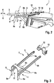
- FIGS. 1 and 2 is a designed as electric fuzzy saw hand tool 1, which has in a housing 2, an electric drive motor for driving a running as a saw blade tool 3.
- the saw blade 3 exercises, as Fig. 2 can be seen, an oscillating, linear working movement according to double arrow 4, in which the saw teeth 5 of the saw blade 3, which are in a sawtooth line 6, are moved back and forth.
- the working movement 4 takes place along the sawtooth line 6.
- the hand tool 1 is provided with a support means 7 which comprises a support member 8 on a support member 9 and a fastener 10 on the housing 2.
- the support element 8 is designed as a support bracket and has two support legs 8a and 8b arranged at an angle to one another, which open outwards and delimit a receiving area 11 for receiving an object or object to be machined.
- the support member 8 is, as the perspective view in accordance with Fig. 1 can be taken U-shaped, wherein each U-leg has two support legs 8a, 8b with an intermediate receiving portion 11.
- the support part 9 comprises two support legs 9a, 9b, which are respectively guided on different sides of the U-shaped support element 8 and fixedly connected to the support element.
- the ends of the two support legs 9a, 9b pivotally connected to the fastener 10, which is detachably arranged on the housing 2 of the power tool 1.
- This embodiment makes it possible, the support means 7 with the support member 8 and the support member 9 about the axis 12 of the pivot joint between the fastener 10 and the support legs 9a, 9b in the pivoting direction 13 (FIGS. Fig. 2 ) to pivot.
- a spring element 14 in the form of a leg spring, the support member 9 including support member 8 in the in Fig. 2 illustrated starting position spring loaded.
- the spring element 14 generates about the axis 12 a moment which acts at the level of the receiving region 11 as a force arrow 15 which acts at least approximately perpendicular to the sawtooth line 6 of the saw blade 3.
- a force opposite to the power arrow 15 must be expended. This force is advantageously less than 10 N, for example 4 N to 9 N.
- the U-shaped support member 8 each have two angular receiving portions 11 which are formed between support legs 8a, 8b.
- the support member 8 is U-shaped, wherein the receiving areas 11 are arranged in the mounted state on different sides of the saw blade.
- a pair of support legs 8a, 8b with intermediate receiving portion 11 is connected to a carrier leg 9a and 9b of the support member 9.
- the axis 12, about which the carrier legs 9 a, 9 b are pivotable, is formed as a journal, which is arranged on the fastening element 10.
- a stub axle is provided on the fastening element 10, wherein the axle journal 12 in associated recesses adjacent to the end faces of the support legs 9a, 9b can be inserted.
- the fastener 10 is releasably secured to the housing of the power tool.
- the attachment takes place, for example, in non-locking or positive manner by clipping the fastener to the housing or in a similar manner.
- Fig. 4 is the support member 8 with registered angle ⁇ between the front supporting leg 8a, which faces the tip of the saw blade 3, and the sawtooth line 6 is shown.
- the angle ⁇ is in an angular range between 90 ° and 120 °, wherein in the embodiment an embodiment between 95 ° and 110 ° is shown.
- On the inside of the support leg 8a is the object to be processed, which is received in the receiving space 11.
- the saw teeth 5 process the object received in the receiving space 11, a counterforce acting against the inside of the front supporting leg 8a.
- Fig. 5 shows the support member 8 on the saw blade 3 with the angle ⁇ between the two support legs 8a and 8b in the region of the receiving space 11.
- the angle ⁇ indicates the opening angle of the receiving space 11.
- the angle ⁇ lies in a value range between 50 ° and 70 °, in particular between 55 ° and 65 °.
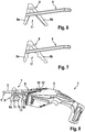
- FIGS. 6 and 7 Further embodiments of the support member 8 on the support part 9 are shown.
- the inner sides of the angularly oriented support legs 8a and 8b are in the embodiment according to the FIGS. 1 to 5 smooth-walled, according to the embodiment Fig. 6 however, provided with teeth which are directed towards the acute angle of the receiving space 11, to assist a hooking of the recorded object.
- Fig. 7 it is provided that the inside of the support legs 8a, 8b is formed wave-shaped, which allows the inclusion of different sized objects in certain, discrete positions.
- FIGS. 8 to 10 the hand tool 1 is shown at various stages during the processing of an object 16.
- Fig. 8 represents the initial state in which the support means 7 is in its initial position.
- the article 16 has a round cross-section, it is, for example, a branch or a branch.
- the article 16 extends transversely to the plane of the saw blade 3 and is severed by the saw teeth 5 in the workpiece processing by the working movement of the saw blade.
- the article 16 is securely received in the receiving area 11 between the angularly arranged support legs 8a, 8b and is supported on the inner sides of the support legs 8a, 8b during the sawing process.
- Fig. 9 shows the machining state with the saw blade 3 approximately in the half-sawed state of the article 16. Due to the pivoting movement of the support means 7 about the pivot axis 11 changes in workpiece machining, the relative angle between the support member 8 including the received therein article 16 and the saw blade 3. After the article 16 was completely severed ( Fig. 10 ), the support means 7 as with the arrow in Fig. 10 represented by the action of the spring element to pivot back to its original position.
- the support member 8 is also formed as a support bracket and has the two angularly arranged support legs 8a and 8b, which limit the intermediate, angular receiving portion 11 for receiving the object to be processed.
- the structure of the support element 8 and the carrier part 9 corresponds to that of Fig. 6 ,
- a limiting element 17 is provided, which is fixed to the housing or fastened to a base plate of the power tool.
- the limiting element 17 has, as Fig. 12 can be seen, two lateral boundary walls on, the end-side ends 17a are bent to the outside and of corresponding, frontal ends 8c, which are bent inwards and located on the front side of the rear support leg 8b, are engaged behind a positive fit.
- Fig. 12 is the maximum Jerusalemschwenkte state of the support device shown, in which the ends 17a of the limiting element 17 are in contact or stop to the corresponding ends 8c of the rear support legs 8b.
- the ends 8c of the support legs 8b can move until reaching the stop on the outside of the boundary walls of the limiting element 17 during the pivoting movement along, so that the Aufschwenkamba of the support element 8 is not hindered by the limiting element 17 until reaching the upper stop.
- a hook 18 is formed on the limiting element 17, which serves for the releasable attachment of the limiting element 17 in a corresponding receptacle on the base plate or on the housing of the power tool.
- the limiting element 17 is also in the Fig. 8 to 10 shown.
Landscapes
- Engineering & Computer Science (AREA)
- Mechanical Engineering (AREA)
- Sawing (AREA)
Description
- Die Erfindung bezieht sich auf eine Stützeinrichtung für eine Werkzeugmaschine.
- Bekannt sind motorisch angetriebene Handsägen, beispielsweise elektromotorisch angetriebene Fuchsschwanzsägen, bei denen das Sägeblatt eine lineare, oszillierende Arbeitsbewegung ausführt. Werden mit derartigen Handsägen dünne Zweige an Bäumen bzw. Sträucher geschnitten, tritt das Problem auf, dass die Zweige auf Grund ihrer Biegsamkeit unter der Kraft, welche die Sägezähne auf den durchzusägenden Zweig ausüben, zurückweichen, was ein Durchsägen erschwert oder sogar unmöglich macht. Zur Erhöhung des Widerstands müssen die Zweige manuell gehalten werden, was jedoch ein erhebliches Gefahrenpotenzial birgt.
- Aus der
DE 85 07 971 U ist eine Stützeinrichtung, gemäss dem Oberbegriff des Anspruchs 1, für eine Stichsäge bekannt, die ein Stützelement in Form eines Stützwinkels mit zwei winklig zueinander angeordneten Stützschenkeln aufweist. Das Stützelement ist über ein Drehgelenk schwenkbar am Gehäuse der Handwerkzeugmaschine gelagert, wobei sich das Drehgelenk an einem einteilig mit dem hinteren Stützschenkel ausgebildeten Flansch des Stützelementes befindet. Der vordere Schenkel des Stützelementes ist mit dem hinteren Schenkel verbunden und kann beim Einführen eines Astes oder Rohres in den winkligen Aufnahmebereich aufgedrückt werden. - Das Stützelement ist mit Backen versehen, die sich an die seitlichen Flanken des Sägeblattes der Stichsäge anlegen, wobei im Bereich der Backen ein Quersteg angeordnet ist. Die Backen liegen mit Reibung am Sägeblatt an.
- Die
WO 2009/061749 A2 zeigt eine Stützeinrichtung, welche schwenkbar am Gehäuse einer Handwerkzeugmaschine angeschlagen werden kann und zwei links und rechts eines Schneidblattes der Handwerkzeugmaschine angeordnete Stützwinkel aufweist. - Die
US 6,067716 (D3) zeigt ein Stützelement, das als ein verhältnismäßig massiver Block ausgeführt ist, in den ein Schlitz für ein Sägeblatt eingebracht ist. Der Block wird an einer Seite in eine Aufnahmeeinrichtung am Gehäuse der Handwerkzeugmaschine eingeschoben, an der eine Nut mit Hinterschnitt gebildet ist, welche einen entsprechenden Hinterschnitt am Stützelement umgreift. - Der Erfindung liegt die Aufgabe zu Grunde, mit einfachen konstruktiven Maßnahmen eine Stützeinrichtung für eine Werkzeugmaschine zu schaffen, die es erlaubt, Objekte zu bearbeiten, welche der Arbeitsbewegung des Werkzeugs der Werkzeugmaschine nur einen geringen Widerstand entgegensetzen.
- Diese Aufgabe wird erfindungsgemäß mit den Merkmalen des Anspruches 1 gelöst. Die Unteransprüche geben zweckmäßige Weiterbildungen an.
- Die erfindungsgemäße Stützeinrichtung kann in Werkzeugmaschinen eingesetzt werden, insbesondere in Handwerkzeugmaschinen wie z.B. motorisch angetriebenen Handsägen und dient zur Abstützung eines von einem Werkzeug der Werkzeugmaschine zu bearbeitenden Gegenstandes bzw. Objekts. Um auch Gegenstände bzw. Objekte mit der erforderlichen Genauigkeit und Effizient bearbeiten zu können, die in Richtung der Arbeitsbewegung des Werkzeugs nur einen geringen Widerstand entgegensetzen, beispielsweise Zweige bzw. kleine Äste, weist die Stützeinrichtung ein Stützelement auf, das mit einem Aufnahmebereich zur Aufnahme des zu bearbeitenden Gegenstands versehen ist. Das Stützelement ist am Gehäuse der Werkzeugmaschine schwenkbar gelagert. Der Aufnahmebereich ist von einer Stützwand des Stützelementes begrenzt, an der der zu bearbeitende Gegenstand, welcher im Aufnahmebereich aufgenommen ist, anliegt. Die Stützwand ermöglicht eine Abstützung des Gegenstandes entgegengesetzt zur motorischen Arbeitsbewegung des Werkzeugs der Werkzeugmaschine.
- Diese Stützeinrichtung ermöglicht es, beispielsweise Zweige in den Aufnahmebereich des Stützelementes aufzunehmen, wobei die Abstützung des Zweigs über die Stützwand des Stützelementes erfolgt. Die Stützwand nimmt die Stützkraft auf, welche als Reaktionskraft bei der Bearbeitung des Gegenstands bzw. Objekts als Reaktion auf die Arbeitsbewegung des Werkzeugs entsteht. Beispielsweise werden bei einer linearen Sägebewegung eines Sägeblatts durch den Kontakt der Sägezähne mit dem Gegenstand Stützkräfte entgegen der Sägebewegung erzeugt, welche von der Stützwand der Stützeinrichtung aufgenommen werden. Auf ein zusätzliches Halten bzw. Sichern des zu bearbeitenden Gegenstandes kann verzichtet werden.
- Das Stützelement ist vorteilhafterweise als ein Stützwinkel ausgebildet, welcher zwei winklig zueinander ausgerichtete Stützschenkel aufweist, die den Aufnahmebereich begrenzen. In dem sich winklig öffnenden Aufnahmebereich können Objekte wie zum Beispiel Äste mit unterschiedlichem Durchmesser aufgenommen werden, wobei eine Abstützung gegen die motorische Arbeitsbewegung des Werkzeugs gegeben ist. Einer der Stützschenkel, vorzugsweise beide Stützschenkel bilden hierbei jeweils eine Stützwand, an der sich das zu bearbeitende Objekt abstützt.
- Die Stützwand des Stützelementes nimmt mit der Achse bzw. Linie der Arbeitsbewegung des Werkzeugs einen Winkel ein, der vorteilhafterweise zwischen 90° und 120° liegt, insbesondere zwischen 95° und 110°. Im Falle des Stützwinkels mit den zwei winklig zueinander ausgerichteten Stützschenkeln können diese zueinander einen Winkel von 50° bis 70° einschließen, insbesondere einen Winkel zwischen 55° und 65°. Dieser Winkelbereich stellt zum einen sicher, dass ein ausreichend großer Aufnahmebereich zur Aufnahme unterschiedlich großer Objekte gegeben ist. Zum anderen ermöglicht der Winkel, den die Stützwand mit der Achse der Arbeitsbewegung des Werkzeugs einnimmt, einen sichere Abstützung und Aufnahme der Reaktionskräfte über die Stützwand. Der hintere Stützschenkel des Stützwinkels nimmt im maximal aufgeschwungenen Zustand - bei vollständig durchtrenntem Gegenstand - zweckmäßigerweise zumindest annähernd den gleichen Winkel mit der Achse bzw. Linie der Arbeitsbewegung des Werkzeugs ein wie der vordere Stützschenkel im Ausgangszustand, also vor dem Durchtrennen des Gegenstands. Des Weiteren ist es vorteilhaft, dass der maximale Schwenkwinkel, den das Stützelement ausführen kann, und der Winkel, den die beiden Stützschenkel zueinander einnehmen, zumindest annähernd gleich groß sind.
- Des Weiteren ist es zweckmäßig, die Position der Achse, um die das Stützelement am Gehäuse schwenkbar gelagert ist, in Abhängigkeit des Durchmessers des zu bearbeitenden Gegenstandes näher oder weiter entfernt zum Werkzeug der Handwerkzeugmaschine zu positionieren. Bei größeren Durchmessern ist es vorteilhaft, dass die Achse sich näher am Werkzeug befindet, bei kleineren Durchmessern befindet sich dagegen die Achse weiter vom Werkzeug entfernt.
- Die Achse des Stützelementes befindet sich beispielsweise in der Ausführung des Werkzeugs als Sägeblatt in einer Linie, die mit der Sägezahnlinie übereinstimmt oder mit der Sägezahnlinie einen kleinen Winkel von vorteilhaft kleiner 10°, insbesondere kleiner oder gleich 5° einnimmt.
- Die schwenkbare Lagerung des Stützelementes am Gehäuse der Werkzeugmaschine erlaubt eine Relativschwenkbewegung des Stützelementes einschließlich des darin aufgenommenen Objektes gegenüber dem Werkzeug während der Objektbearbeitung. So kann beispielsweise im Falle eines eine lineare, oszillierende Sägebewegung ausführenden Sägeblatts das Stützelement einschließlich des darin aufgenommenen Objektes über die Schwenkbewegung über die Sägezahnlinie des Sägeblatts geführt werden, so dass das Objekt im Stützelement von den Sägezähnen durchtrennt wird. Mit dem Kontakt der Sägezähne am Objekt wirken hierbei Reaktionskräfte auf das Objekt, die von der Stützwand am Stützelement aufgenommen werden. Die Schwenkbewegung erfolgt senkrecht zur Arbeitsbewegung des Werkzeugs, also im Falle des Sägeblatts senkrecht zur Sägezahnlinie.
- Vorteilhafterweise ist das Stützelement über ein Federelement in eine Ausgangsposition kraftbeaufschlagt, wobei es sich bei dem Federelement zweckmäßigerweise um eine Schenkel- bzw. Drehfeder handelt. Das Federelement übt eine Kraft bzw. ein Moment um den Schwenkpunkt des Stützelementes am Gehäuse der Werkzeugmaschine aus. Bei der Werkstückbearbeitung wird das Stützelement einschließlich des darin aufgenommenen, zu bearbeitenden Objektes gegen die Sägezähne verschwenkt, wobei die Schwenkbewegung entgegen der Kraft bzw. des Momentes des Federelementes erfolgt. Vorteilhafterweise ist das Federelement so dimensioniert, dass die Kraft in Höhe des Stützelementes, welche aufgebracht werden muss, um das Stützelement gegen das Federelement zu verschwenken, nur wenige Newton beträgt, insbesondere weniger als 10 N, beispielsweise 4 N. Diese Kraft wirkt somit auf das im Stützelement aufgenommene Objekt. Dies bedeutet, dass beispielsweise Zweige, welche im Stützelement aufgenommen sind, und durchtrennt werden sollen, lediglich diese Kraft aufnehmen müssen, die senkrecht zur Arbeitsbewegung des Werkzeuges gerichtet ist.
- Gemäß weiterer zweckmäßiger Ausführung ist vorgesehen, dass das Stützelement an einem Trägerteil gehalten ist, das schwenkbar am Gehäuse der Werkzeugmaschine festlegbar ist. Das Trägerteil weist zwei Trägerschenkel auf, die fest mit dem Stützelement verbunden sind und gehäuseseitig an einem Befestigungselement schwenkbar gelagert sind, das lösbar mit dem Gehäuse verbunden werden kann. Die Trägerschenkel überbrücken die Distanz zwischen der Schwenkachse am Gehäuse und dem Aufnahmebereich im Stützelement. Das lösbar am Gehäuse festgelegte Befestigungselement, welches zugleich eine Schwenkachse für das Trägerteil aufweist, kann bedarfsweise am Gehäuse befestigt bzw. von diesem entfernt werden. Die Aufteilung in ein Befestigungselement, ein Trägerteil und ein Stützelement erlaubt eine flexible Anpassung an unterschiedliche Werkzeugmaschinengeometrien.
- Weitere Vorteile und zweckmäßige Ausführungen sind den weiteren Ansprüchen, der Figurenbeschreibung und den Zeichnungen zu entnehmen. Es zeigen:
- Fig. 1
- eine perspektivische Darstellung einer elektromotorischen Handsäge, die als Werkzeug ein Sägeblatt aufweist, das eine lineare, oszillierende Sägebewegung ausübt, mit einer Stützeinrichtung zur Aufnahme eines zu bearbeitenden Objektes, wobei die Stützeinrichtung schwenkbar am Gehäuse der Werkzeugmaschine angeordnet ist,
- Fig. 2
- die Handwerkzeugmaschine einschließlich Stützeinrichtung in Seitenansicht,
- Fig. 3
- die Stützeinrichtung in perspektivischer Darstellung,
- Fig. 4
- in Seitenansicht die Stützeinrichtung einschließlich Sägeblatt mit Winkelangaben für einen vorne liegenden Stützschenkel eines Stützwinkels der Stützeinrichtung,
- Fig. 5
- eine
Fig. 4 entsprechende Darstellung, mit einer Winkelangabe zwischen zwei Stützschenkeln des Stützwinkels, - Fig. 6
- eine Ausführungsvariante der Stützeinrichtung mit einem Stützwinkel, dessen Stützschenkel an der Innenseite eine Verzahnung aufweisen,
- Fig. 7
- eine weitere Ausführungsvariante mit einer wellenförmigen Innenkontur der Stützschenkel,
- Fig. 8 bis 10
- die Handwerkzeugmaschine in verschiedenen Stadien während der Objektbearbeitung,
- Fig. 11
- die Stützeinrichtung in Seitenansicht mit einem Begrenzungselement an einem Stützschenkel zur Begrenzung der Schwenkbewegung,
- Fig. 12
- die Stützeinrichtung aus
Fig. 9 in einer Ansicht von vorne. - In den Figuren sind gleiche Bauteile mit gleichen Bezugszeichen versehen.
- In den
Figuren 1 und2 ist eine als elektrische Fuchsschwanzsäge ausgeführte Handwerkzeugmaschine 1 dargestellt, die in einem Gehäuse 2 einen elektrischen Antriebsmotor zum Antreiben eines als Sägeblatt ausgeführten Werkzeugs 3 aufweist. Das Sägeblatt 3 übt, wieFig. 2 zu entnehmen, eine oszillierende, lineare Arbeitsbewegung gemäß Doppelpfeil 4 aus, bei der die Sägezähne 5 des Sägeblatts 3, die in einer Sägezahnlinie 6 stehen, vor und zurück bewegt werden. Die Arbeitsbewegung 4 erfolgt entlang der Sägezahnlinie 6. - Wie den
Figuren 1 und2 weiter zu entnehmen, ist die Handwerkzeugmaschine 1 mit einer Stützeinrichtung 7 versehen, die ein Stützelement 8 an einem Trägerteil 9 sowie ein Befestigungselement 10 am Gehäuse 2 umfasst. Das Stützelement 8 ist als Stützwinkel ausgebildet und weist zwei winklig zueinander angeordnete Stützschenkel 8a und 8b auf, die sich nach außen hin öffnen und einen Aufnahmebereich 11 zur Aufnahme eines zu bearbeitenden Gegenstandes bzw. Objekts begrenzen. Das Stützelement 8 ist, wie der perspektivischen Darstellung gemäßFig. 1 zu entnehmen, U-förmig ausgebildet, wobei jeder U-Schenkel zwei Stützschenkel 8a, 8b mit einem zwischenliegenden Aufnahmebereich 11 aufweist. - Das Trägerteil 9 umfasst zwei Trägerschenkel 9a, 9b, die jeweils an verschiedenen Seiten des U-förmigen Stützelementes 8 geführt und mit dem Stützelement fest verbunden sind. Auf der dem Stützelement 8 gegenüberliegenden Seite sind die Enden der beiden Trägerschenkel 9a, 9b schwenkbar mit dem Befestigungselement 10 verbunden, das lösbar am Gehäuse 2 der Handwerkzeugmaschine 1 angeordnet ist. Diese Ausführung ermöglicht es, die Stützeinrichtung 7 mit dem Stützelement 8 und dem Trägerteil 9 um die Achse 12 des Schwenkgelenks zwischen Befestigungselement 10 und den Trägerschenkeln 9a, 9b in Schwenkrichtung 13 (
Fig. 2 ) zu verschwenken. - Wie
Fig. 2 außerdem zu entnehmen, ist um die Achse 12 des Schwenkgelenks zwischen dem Befestigungselement 10 und den Trägerschenkeln 9a, 9b ein Federelement 14 in Form einer Schenkelfeder gelegt, die das Trägerteil 9 einschließlich Stützelement 8 in die inFig. 2 dargestellte Ausgangsposition federbelastet. Das Federelement 14 generiert um die Achse 12 ein Moment, das in Höhe des Aufnahmebereichs 11 als ein Kraftpfeil 15 wirkt, welcher zumindest annähernd senkrecht zur Sägezahnlinie 6 des Sägeblatts 3 wirkt. Um das Stützelement 8 gegen die Kraft des Federelements 14 nach oben verschwenken zu können, muss eine Kraft entgegengesetzt zum Kraftpfeil 15 aufgewandt werden. Diese Kraft beträgt vorteilhafterweise weniger als 10 N, beispielsweise 4 N bis 9 N. - Wie der Einzeldarstellung der Stützeinrichtung 7 gemäß
Fig. 3 zu entnehmen, weist das U-förmig ausgebildete Stützelement 8 jeweils zwei winkelförmige Aufnahmebereiche 11 auf, die zwischen Stützschenkeln 8a, 8b gebildet sind. Das Stützelement 8 ist U-förmig ausgebildet, wobei die Aufnahmebereiche 11 im montierten Zustand auf verschiedenen Seiten des Sägeblattes angeordnet sind. Je ein Paar Stützschenkel 8a, 8b mit zwischenliegendem Aufnahmebereich 11 ist mit einem Trägerschenkel 9a bzw. 9b des Trägerteils 9 verbunden. - Die Achse 12, um die die Trägerschenkel 9a, 9b verschwenkbar sind, ist als ein Achszapfen ausgebildet, der an dem Befestigungselement 10 angeordnet ist. Pro Trägerschenkel 9a, 9b ist ein Achszapfen am Befestigungselement 10 vorgesehen, wobei der Achszapfen 12 in zugeordnete Ausnehmungen benachbart zu den Stirnseiten der Trägerschenkel 9a, 9b einführbar ist.
- Das Befestigungselement 10 ist lösbar am Gehäuse der Handwerkzeugmaschine zu befestigen. Die Befestigung erfolgt beispielsweise in rast- bzw. formschlüssiger Weise durch Aufklipsen des Befestigungselementes am Gehäuse oder in ähnlicher Weise.
- In
Fig. 4 ist das Stützelement 8 mit eingetragenem Winkel α zwischen dem vorne liegenden Stützschenkel 8a, welcher der Spitze des Sägeblatts 3 zugewandt ist, und der Sägezahnlinie 6 dargestellt. Der Winkel α liegt in einem Winkelbereich zwischen 90° und 120°, wobei im Ausführungsbeispiel ein Ausführungsbeispiel zwischen 95° und 110° dargestellt ist. An der Innenseite des Stützschenkels 8a liegt das zu bearbeitende Objekt an, welches im Aufnahmeraum 11 aufgenommen ist. Bei einer Rückwärtsbewegung des Sägeblatts 3 bearbeiten die Sägezähne 5 das im Aufnahmeraum 11 aufgenommene Objekt, wobei gegen die Innenseite des vorne liegenden Stützschenkels 8a eine Gegenkraft wirkt. -
Fig. 5 zeigt das Stützelement 8 am Sägeblatt 3 mit dem Winkel β zwischen den beiden Stützschenkeln 8a und 8b im Bereich des Aufnahmeraums 11. Der Winkel β gibt den Öffnungswinkel des Aufnahmeraums 11 an. Der Winkel β liegt in einem Wertebereich zwischen 50° und 70°, insbesondere zwischen 55° und 65°. - In den
Figuren 6 und 7 sind weitere Ausführungsbeispiele für das Stützelement 8 am Trägerteil 9 dargestellt. Die Innenseiten der winklig ausgerichteten Stützschenkel 8a und 8b sind beim Ausführungsbeispiel gemäß denFiguren 1 bis 5 glattwandig ausgebildet, beim Ausführungsbeispiel gemäßFig. 6 jedoch mit Zähnen versehen, welche in Richtung des spitzen Winkels des Aufnahmeraums 11 gerichtet sind, um ein Festhaken des aufgenommenen Objekts zu unterstützen. GemäßFig. 7 ist vorgesehen, dass die Innenseite der Stützschenkel 8a, 8b wellenförmig ausgebildet ist, was die Aufnahme unterschiedlich großer Objekte in bestimmten, diskreten Positionen erlaubt. - In den
Figuren 8 bis 10 ist die Handwerkzeugmaschine 1 in verschiedenen Stadien während der Bearbeitung eines Gegenstands bzw. Objekts 16 dargestellt.Fig. 8 stellt den Ausgangszustand dar, in welchem sich die Stützeinrichtung 7 in ihrer Ausgangsposition befindet. Der Gegenstand 16 weist einen runden Querschnitt auf, es handelt sich beispielsweise um einen Ast bzw. einen Zweig. Der Gegenstand 16 erstreckt sich quer zur Ebene des Sägeblatts 3 und wird bei der Werkstückbearbeitung durch die Arbeitsbewegung des Sägeblatts von den Sägezähnen 5 durchtrennt. Der Gegenstand 16 ist im Aufnahmebereich 11 zwischen den winklig angeordneten Stützschenkeln 8a, 8b sicher aufgenommen und stützt sich während des Sägevorganges an den Innenseiten der Stützschenkel 8a, 8b ab. Auf Grund der Neigung der Sägezähne 5 entgegengesetzt zur Spitze des Sägeblattes wird insbesondere bei einer Rückwärtsbewegung des Sägeblattes in Richtung auf das Gehäuse 2 zu ein Sägeschnitt in den Gegenstand 16 eingebracht, hierbei wirkt eine Reaktions- bzw. Stützkraft auf die Innenseite des vorderen Stützschenkels 8a. -
Fig. 9 zeigt den Bearbeitungszustand mit dem Sägeblatt 3 etwa im halbdurchsägten Zustand des Gegenstandes 16. Durch die Schwenkbeweglichkeit der Stützeinrichtung 7 um die Schwenkachse 11 ändert sich bei der Werkstückbearbeitung der Relativwinkel zwischen dem Stützelement 8 einschließlich des darin aufgenommenen Gegenstandes 16 und dem Sägeblatt 3. Nachdem der Gegenstand 16 vollständig durchtrennt wurde (Fig. 10 ), kann die Stützeinrichtung 7 wie mit dem Pfeil inFig. 10 dargestellt durch die Wirkung des Federelementes wieder in ihre Ausgangsposition zurück verschwenken. - In dem in den
Fig. 11 und 12 dargestellten Ausführungsbeispiel ist das Stützelement 8 ebenfalls als Stützwinkel ausgebildet und weist die zwei winklig zueinander angeordneten Stützschenkel 8a und 8b auf, die den zwischenliegenden, winkelförmigen Aufnahmebereich 11 zur Aufnahme des zu bearbeitenden Gegenstands begrenzen. Der Aufbau des Stützelementes 8 sowie des Trägerteils 9 entspricht demjenigen ausFig. 6 . - Zur Begrenzung der Ausschwenkbewegung ist ein Begrenzungselement 17 vorgesehen, das gehäusefest bzw. an einer Fußplatte der Handwerkzeugmaschine befestigbar ist. Das Begrenzungselement 17 weist, wie
Fig. 12 zu entnehmen, zwei seitliche Begrenzungswände auf, deren stirnseitige Enden 17a nach außen umgebogen sind und von korrespondierenden, stirnseitigen Enden 8c, die nach innen gebogen sind und sich an der Stirnseite der hinteren Stützschenkel 8b befinden, formschlüssig hintergriffen sind. InFig. 12 ist der maximal aufschwenkte Zustand der Stützeinrichtung dargestellt, in welchem die Enden 17a des Begrenzungselementes 17 auf Kontakt bzw. Anschlag zu den korrespondierenden Enden 8c der hinteren Stützschenkel 8b liegen. Die Enden 8c der Stützschenkel 8b können bis zum Erreichen des Anschlags an der Außenseite der Begrenzungswände des Begrenzungselementes 17 während der Schwenkbewegung entlang verfahren, so dass die Aufschwenkbewegung des Stützelementes 8 bis zum Erreichen des oberen Anschlags nicht durch das Begrenzungselement 17 behindert ist. - Wie
Fig. 11 auch zu entnehmen, ist am Begrenzungselement 17 ein Haken 18 angeformt, der zur lösbaren Befestigung des Begrenzungselementes 17 in einer korrespondierenden Aufnahme an der Fußplatte bzw. am Gehäuse der Handwerkzeugmaschine dient. - Das Begrenzungselement 17 ist auch in den
Fig. 8 bis 10 dargestellt.
Claims (12)
- Stützeinrichtung für eine Werkzeugmaschine, insbesondere eine Handwerkzeugmaschine (1), zur Abstützung eines von einem Werkzeug (3) der Werkzeugmaschine (1) zu bearbeitenden Gegenstands (16), mit einem am Gehäuse (2) der Werkzeugmaschine (1) schwenkbar lagerbaren Stützelement (8), das einen Aufnahmebereich (11) zur Aufnahme des Gegenstands (16) aufweist, wobei der Aufnahmebereich (11) von einer Stützwand begrenzt ist, an der sich der im Aufnahmebereich (11) aufgenommene Gegenstand (16) gegen die motorische Arbeitsbewegung des Werkzeugs (3) abstützt, dadurch gekennzeichnet, dass das Stützelement (8) als ein U-förmiger Stützwinkel ausgebildet ist, wobei jeder U-Schenkel zwei winklig zueinander ausgerichtete Stützschenkel (8a, 8b) aufweist, die sich nach außen hin öffnen und den zwischenliegenden Aufnahmebereich (11) aufweisen, dass das Stützelement (8) an einem Trägerteil (9) gehalten ist, das schwenkbar am Gehäuse (2) der Werkzeugmaschine (1) festlegbar ist, dass das Trägerteil (9) zwei Trägerschenkel (9a, 9b) aufweist, die fest mit dem Stützelement (8) verbunden sind, wobei je ein Paar Stützschenkel (8a, 8b) mit einem Trägerschenkel (9a, 9b) des Trägerteils (9) verbunden ist.
- Stützeinrichtung nach Anspruch 1, dadurch gekennzeichnet, dass das Stützelement (8) als Stützwinkel mit zwei winklig zueinander ausgerichteten Stützschenkeln (8a, 8b) ausgebildet sind, zwischen denen der Aufnahmebereich (11) liegt.
- Stützeinrichtung nach Anspruch 2, dadurch gekennzeichnet, dass der Winkel (β) zwischen den Stützschenkeln (8a, 8b) zwischen 50° und 70° liegt, insbesondere zwischen 55° und 65°.
- Stützeinrichtung nach einem der Ansprüche 1 bis 3, dadurch gekennzeichnet, dass die Stützwand des Stützelements (8) mit der Achse (12) der motorischen Arbeitsbewegung des Werkzeugs (3) einen Winkel (α) einschließt, der zwischen 90° und 120° liegt, insbesondere zwischen 95° und 110°.
- Stützeinrichtung nach einem der Ansprüche 1 bis 4, dadurch gekennzeichnet, dass das Stützelement (8) über ein Federelement (14) in eine Ausgangsposition kraftbeaufschlagt ist.
- Stützeinrichtung nach Anspruch 5, dadurch gekennzeichnet, dass das Federelement (14) als Schenkel- bzw. Drehfeder ausgebildet ist.
- Stützeinrichtung nach Anspruch 6, dadurch gekennzeichnet, dass die von dem Federelement (14) erzeugte Federkraft kleiner als 10 N ist, insbesondere zwischen 4 N und 9 N beträgt.
- Stützeinrichtung nach einem der Ansprüche 1 bis 7, dadurch gekennzeichnet, dass das Trägerteil (9) an einem Befestigungselement (10) schwenkbar gelagert ist, das lösbar mit dem Gehäuse (2) zu verbinden ist.
- Stützeinrichtung nach einem der Ansprüche 1 bis 8, dadurch gekennzeichnet, dass zur Begrenzung der Schwenkbewegung des Stützelements (8) ein Begrenzungselement (17) vorgesehen ist, das am Gehäuse (2) bzw. einer Fußplatte der Werkzeugmaschine angeordnet ist.
- Stützeinrichtung nach Anspruch 9, dadurch gekennzeichnet, dass das Begrenzungselement (17) einen Endanschlag für die Schwenkbewegung des Stützelements (8) bildet.
- Stützeinrichtung nach Anspruch 10, dadurch gekennzeichnet, dass das Begrenzungselement (17) Begrenzungswände mit umgebogenen Enden (17a) aufweist, die umgebogene Enden (8c) am Stützelement (8) hintergreifen.
- Werkzeugmaschine, insbesondere Handwerkzeugmaschine, vorzugsweise motorisch angetriebene Handsäge, mit einer Stützeinrichtung (7) nach einem der Ansprüche 1 bis 11.
Applications Claiming Priority (2)
| Application Number | Priority Date | Filing Date | Title |
|---|---|---|---|
| DE102011003883A DE102011003883A1 (de) | 2011-02-09 | 2011-02-09 | Stützeinrichtung für eine Werkzeugmaschine |
| PCT/EP2012/050214 WO2012107253A1 (de) | 2011-02-09 | 2012-01-09 | Stützeinrichtung für eine werkzeugmaschine |
Publications (2)
| Publication Number | Publication Date |
|---|---|
| EP2673101A1 EP2673101A1 (de) | 2013-12-18 |
| EP2673101B1 true EP2673101B1 (de) | 2017-09-20 |
Family
ID=45464595
Family Applications (1)
| Application Number | Title | Priority Date | Filing Date |
|---|---|---|---|
| EP12700105.5A Active EP2673101B1 (de) | 2011-02-09 | 2012-01-09 | Stützeinrichtung für eine werkzeugmaschine |
Country Status (4)
| Country | Link |
|---|---|
| EP (1) | EP2673101B1 (de) |
| CN (1) | CN103379978B (de) |
| DE (1) | DE102011003883A1 (de) |
| WO (1) | WO2012107253A1 (de) |
Cited By (1)
| Publication number | Priority date | Publication date | Assignee | Title |
|---|---|---|---|---|
| EP3831523B1 (de) * | 2019-12-02 | 2026-04-22 | Techtronic Cordless GP | Säbelsäge mit klemmvorrichtung |
Families Citing this family (6)
| Publication number | Priority date | Publication date | Assignee | Title |
|---|---|---|---|---|
| CN103895068B (zh) * | 2012-12-25 | 2016-08-03 | 苏州宝时得电动工具有限公司 | 电动往复锯 |
| CN103084660B (zh) * | 2013-01-14 | 2015-10-28 | 浙江亚特电器有限公司 | 一种往复锯 |
| CN103447614B (zh) * | 2013-08-20 | 2015-10-21 | 江苏苏美达五金工具有限公司 | 一种电动往复锯 |
| CN103785897B (zh) * | 2014-01-27 | 2016-12-07 | 天佑电器(苏州)有限公司 | 夹持装置及具有该夹持装置的电动工具 |
| CN104381034B (zh) * | 2014-10-30 | 2017-03-22 | 浙江亚特电器有限公司 | 一种园林锯 |
| CN106541179B (zh) * | 2017-01-22 | 2019-02-22 | 常州赛迪工具有限公司 | 一种往复锯夹持装置及具有该夹持装置的电动往复锯 |
Family Cites Families (11)
| Publication number | Priority date | Publication date | Assignee | Title |
|---|---|---|---|---|
| DE3428436A1 (de) * | 1984-08-01 | 1986-02-06 | Rems-Werk Christian Föll und Söhne GmbH & Co, 7050 Waiblingen | Tragbare stichsaege |
| DE8507971U1 (de) * | 1985-03-18 | 1985-05-30 | Lytec + Tool GmbH, 6000 Frankfurt | Führungseinrichtung für stangenförmige Werkstücke an Pendelhub- und Säbelsägen |
| GB2206527B (en) * | 1987-07-01 | 1991-12-11 | Phillip William Harold Livesey | Powered cutting tool |
| JPH0637854Y2 (ja) * | 1988-04-11 | 1994-10-05 | 株式会社マキタ | 携帯用レシプロソー |
| JPH07108414A (ja) * | 1993-08-20 | 1995-04-25 | Hitachi Koki Co Ltd | レシプロソー |
| US6067716A (en) * | 1999-03-26 | 2000-05-30 | Carter; Sam W. | Plastic pipe cutter |
| US6484409B2 (en) * | 2000-04-21 | 2002-11-26 | Black & Decker Inc. | Pruner attachment apparatus for a power tool |
| DE102004042026A1 (de) * | 2004-08-31 | 2006-03-02 | Robert Bosch Gmbh | Spannvorrichtung zum werkzeuglosen Einspannen eines Sägeblatts |
| DE102004045624A1 (de) * | 2004-09-21 | 2006-04-06 | Robert Bosch Gmbh | Hubsägemaschine |
| US7743683B2 (en) * | 2006-08-15 | 2010-06-29 | Umagination Labs, L.P. | Systems and methods of a power tool system with interchangeable functional attachments powered by a direct rotational drive |
| DE102008002212B4 (de) * | 2008-06-04 | 2016-10-06 | Hilti Aktiengesellschaft | Handgeführte Hubsägemaschine |
-
2011
- 2011-02-09 DE DE102011003883A patent/DE102011003883A1/de active Pending
-
2012
- 2012-01-09 EP EP12700105.5A patent/EP2673101B1/de active Active
- 2012-01-09 WO PCT/EP2012/050214 patent/WO2012107253A1/de not_active Ceased
- 2012-01-09 CN CN201280007838.2A patent/CN103379978B/zh active Active
Non-Patent Citations (1)
| Title |
|---|
| None * |
Cited By (1)
| Publication number | Priority date | Publication date | Assignee | Title |
|---|---|---|---|---|
| EP3831523B1 (de) * | 2019-12-02 | 2026-04-22 | Techtronic Cordless GP | Säbelsäge mit klemmvorrichtung |
Also Published As
| Publication number | Publication date |
|---|---|
| CN103379978B (zh) | 2016-08-17 |
| CN103379978A (zh) | 2013-10-30 |
| DE102011003883A1 (de) | 2012-08-09 |
| EP2673101A1 (de) | 2013-12-18 |
| WO2012107253A1 (de) | 2012-08-16 |
Similar Documents
| Publication | Publication Date | Title |
|---|---|---|
| DE102007009943B3 (de) | Hubsäge, insbesondere Stichsäge | |
| WO2012107253A1 (de) | Stützeinrichtung für eine werkzeugmaschine | |
| EP3581309B1 (de) | Werkzeugmaschine, mit einer hin- und hergehenden abtriebsspindel | |
| DE102013204372B4 (de) | Hubsägeblatt für eine Werkzeugmaschine | |
| DE102011078488A1 (de) | Werkzeug | |
| WO2013034344A1 (de) | Sägeblatt für eine werkzeugmaschine | |
| DE102004024092B3 (de) | Führungsadapter mit Krallenkontur | |
| EP3256297B1 (de) | Hand-trennmaschine mit einer tiefeneinstelleinrichtung | |
| EP3703912B1 (de) | Stützzusatzeinrichtung für eine werkstückauflageeinrichtung | |
| DE202006019496U1 (de) | Fliesenschneidemaschine | |
| EP3038780B1 (de) | Gegengewichtsvorrichtung | |
| DE3428436A1 (de) | Tragbare stichsaege | |
| EP2311591B1 (de) | Schärfgerät zum manuellen Schärfen der Schneidzähne von Sägeketten für Kettensägen | |
| DE202009013018U1 (de) | Aufnahme- und Führungsvorrichtung zur Aufnahme eines Werkstücks und Führung eines Zerspanungswerkzeugs | |
| DE102008030024A1 (de) | Vorsatz für einen Oszillationsantrieb | |
| EP2029304B1 (de) | Führungseinrichtung für ein hubbewegungen durchführendes sägeblatt | |
| EP3015230B1 (de) | Sägehilfsvorrichtung mit einer kettensäge | |
| DE29918673U1 (de) | Holzspalter | |
| WO2013117352A1 (de) | Sägeblatt | |
| DE202008014321U1 (de) | Werkzeughalter für eine oszillierende Blechsäge oder -feile | |
| EP2829343A1 (de) | Schärfgerät zum Schärfen von Sägeketten und Sägeblättern | |
| DE102011085411A1 (de) | Sägemaschine, insbesondere Kreissägemaschine | |
| DE8408651U1 (de) | Raeumgeraet | |
| AT501267B1 (de) | Messerhalterung | |
| EP2813333A1 (de) | Ablängwerkzeug |
Legal Events
| Date | Code | Title | Description |
|---|---|---|---|
| PUAI | Public reference made under article 153(3) epc to a published international application that has entered the european phase |
Free format text: ORIGINAL CODE: 0009012 |
|
| 17P | Request for examination filed |
Effective date: 20130909 |
|
| AK | Designated contracting states |
Kind code of ref document: A1 Designated state(s): AL AT BE BG CH CY CZ DE DK EE ES FI FR GB GR HR HU IE IS IT LI LT LU LV MC MK MT NL NO PL PT RO RS SE SI SK SM TR |
|
| DAX | Request for extension of the european patent (deleted) | ||
| GRAP | Despatch of communication of intention to grant a patent |
Free format text: ORIGINAL CODE: EPIDOSNIGR1 |
|
| INTG | Intention to grant announced |
Effective date: 20170606 |
|
| GRAS | Grant fee paid |
Free format text: ORIGINAL CODE: EPIDOSNIGR3 |
|
| GRAA | (expected) grant |
Free format text: ORIGINAL CODE: 0009210 |
|
| AK | Designated contracting states |
Kind code of ref document: B1 Designated state(s): AL AT BE BG CH CY CZ DE DK EE ES FI FR GB GR HR HU IE IS IT LI LT LU LV MC MK MT NL NO PL PT RO RS SE SI SK SM TR |
|
| REG | Reference to a national code |
Ref country code: GB Ref legal event code: FG4D Free format text: NOT ENGLISH |
|
| REG | Reference to a national code |
Ref country code: CH Ref legal event code: EP |
|
| REG | Reference to a national code |
Ref country code: AT Ref legal event code: REF Ref document number: 929763 Country of ref document: AT Kind code of ref document: T Effective date: 20171015 |
|
| REG | Reference to a national code |
Ref country code: IE Ref legal event code: FG4D Free format text: LANGUAGE OF EP DOCUMENT: GERMAN |
|
| REG | Reference to a national code |
Ref country code: DE Ref legal event code: R096 Ref document number: 502012011306 Country of ref document: DE |
|
| REG | Reference to a national code |
Ref country code: NL Ref legal event code: MP Effective date: 20170920 |
|
| PG25 | Lapsed in a contracting state [announced via postgrant information from national office to epo] |
Ref country code: FI Free format text: LAPSE BECAUSE OF FAILURE TO SUBMIT A TRANSLATION OF THE DESCRIPTION OR TO PAY THE FEE WITHIN THE PRESCRIBED TIME-LIMIT Effective date: 20170920 Ref country code: LT Free format text: LAPSE BECAUSE OF FAILURE TO SUBMIT A TRANSLATION OF THE DESCRIPTION OR TO PAY THE FEE WITHIN THE PRESCRIBED TIME-LIMIT Effective date: 20170920 Ref country code: HR Free format text: LAPSE BECAUSE OF FAILURE TO SUBMIT A TRANSLATION OF THE DESCRIPTION OR TO PAY THE FEE WITHIN THE PRESCRIBED TIME-LIMIT Effective date: 20170920 Ref country code: NO Free format text: LAPSE BECAUSE OF FAILURE TO SUBMIT A TRANSLATION OF THE DESCRIPTION OR TO PAY THE FEE WITHIN THE PRESCRIBED TIME-LIMIT Effective date: 20171220 Ref country code: SE Free format text: LAPSE BECAUSE OF FAILURE TO SUBMIT A TRANSLATION OF THE DESCRIPTION OR TO PAY THE FEE WITHIN THE PRESCRIBED TIME-LIMIT Effective date: 20170920 |
|
| REG | Reference to a national code |
Ref country code: LT Ref legal event code: MG4D |
|
| PG25 | Lapsed in a contracting state [announced via postgrant information from national office to epo] |
Ref country code: RS Free format text: LAPSE BECAUSE OF FAILURE TO SUBMIT A TRANSLATION OF THE DESCRIPTION OR TO PAY THE FEE WITHIN THE PRESCRIBED TIME-LIMIT Effective date: 20170920 Ref country code: BG Free format text: LAPSE BECAUSE OF FAILURE TO SUBMIT A TRANSLATION OF THE DESCRIPTION OR TO PAY THE FEE WITHIN THE PRESCRIBED TIME-LIMIT Effective date: 20171220 Ref country code: GR Free format text: LAPSE BECAUSE OF FAILURE TO SUBMIT A TRANSLATION OF THE DESCRIPTION OR TO PAY THE FEE WITHIN THE PRESCRIBED TIME-LIMIT Effective date: 20171221 Ref country code: LV Free format text: LAPSE BECAUSE OF FAILURE TO SUBMIT A TRANSLATION OF THE DESCRIPTION OR TO PAY THE FEE WITHIN THE PRESCRIBED TIME-LIMIT Effective date: 20170920 |
|
| PG25 | Lapsed in a contracting state [announced via postgrant information from national office to epo] |
Ref country code: NL Free format text: LAPSE BECAUSE OF FAILURE TO SUBMIT A TRANSLATION OF THE DESCRIPTION OR TO PAY THE FEE WITHIN THE PRESCRIBED TIME-LIMIT Effective date: 20170920 |
|
| PG25 | Lapsed in a contracting state [announced via postgrant information from national office to epo] |
Ref country code: CZ Free format text: LAPSE BECAUSE OF FAILURE TO SUBMIT A TRANSLATION OF THE DESCRIPTION OR TO PAY THE FEE WITHIN THE PRESCRIBED TIME-LIMIT Effective date: 20170920 Ref country code: PL Free format text: LAPSE BECAUSE OF FAILURE TO SUBMIT A TRANSLATION OF THE DESCRIPTION OR TO PAY THE FEE WITHIN THE PRESCRIBED TIME-LIMIT Effective date: 20170920 Ref country code: ES Free format text: LAPSE BECAUSE OF FAILURE TO SUBMIT A TRANSLATION OF THE DESCRIPTION OR TO PAY THE FEE WITHIN THE PRESCRIBED TIME-LIMIT Effective date: 20170920 Ref country code: RO Free format text: LAPSE BECAUSE OF FAILURE TO SUBMIT A TRANSLATION OF THE DESCRIPTION OR TO PAY THE FEE WITHIN THE PRESCRIBED TIME-LIMIT Effective date: 20170920 |
|
| PG25 | Lapsed in a contracting state [announced via postgrant information from national office to epo] |
Ref country code: IT Free format text: LAPSE BECAUSE OF FAILURE TO SUBMIT A TRANSLATION OF THE DESCRIPTION OR TO PAY THE FEE WITHIN THE PRESCRIBED TIME-LIMIT Effective date: 20170920 Ref country code: IS Free format text: LAPSE BECAUSE OF FAILURE TO SUBMIT A TRANSLATION OF THE DESCRIPTION OR TO PAY THE FEE WITHIN THE PRESCRIBED TIME-LIMIT Effective date: 20180120 Ref country code: SM Free format text: LAPSE BECAUSE OF FAILURE TO SUBMIT A TRANSLATION OF THE DESCRIPTION OR TO PAY THE FEE WITHIN THE PRESCRIBED TIME-LIMIT Effective date: 20170920 Ref country code: SK Free format text: LAPSE BECAUSE OF FAILURE TO SUBMIT A TRANSLATION OF THE DESCRIPTION OR TO PAY THE FEE WITHIN THE PRESCRIBED TIME-LIMIT Effective date: 20170920 Ref country code: EE Free format text: LAPSE BECAUSE OF FAILURE TO SUBMIT A TRANSLATION OF THE DESCRIPTION OR TO PAY THE FEE WITHIN THE PRESCRIBED TIME-LIMIT Effective date: 20170920 |
|
| REG | Reference to a national code |
Ref country code: DE Ref legal event code: R097 Ref document number: 502012011306 Country of ref document: DE |
|
| PLBE | No opposition filed within time limit |
Free format text: ORIGINAL CODE: 0009261 |
|
| STAA | Information on the status of an ep patent application or granted ep patent |
Free format text: STATUS: NO OPPOSITION FILED WITHIN TIME LIMIT |
|
| PG25 | Lapsed in a contracting state [announced via postgrant information from national office to epo] |
Ref country code: DK Free format text: LAPSE BECAUSE OF FAILURE TO SUBMIT A TRANSLATION OF THE DESCRIPTION OR TO PAY THE FEE WITHIN THE PRESCRIBED TIME-LIMIT Effective date: 20170920 |
|
| 26N | No opposition filed |
Effective date: 20180621 |
|
| REG | Reference to a national code |
Ref country code: CH Ref legal event code: PL |
|
| GBPC | Gb: european patent ceased through non-payment of renewal fee |
Effective date: 20180109 |
|
| PG25 | Lapsed in a contracting state [announced via postgrant information from national office to epo] |
Ref country code: MT Free format text: LAPSE BECAUSE OF FAILURE TO SUBMIT A TRANSLATION OF THE DESCRIPTION OR TO PAY THE FEE WITHIN THE PRESCRIBED TIME-LIMIT Effective date: 20170920 |
|
| PG25 | Lapsed in a contracting state [announced via postgrant information from national office to epo] |
Ref country code: LU Free format text: LAPSE BECAUSE OF NON-PAYMENT OF DUE FEES Effective date: 20180109 Ref country code: FR Free format text: LAPSE BECAUSE OF NON-PAYMENT OF DUE FEES Effective date: 20180131 |
|
| REG | Reference to a national code |
Ref country code: IE Ref legal event code: MM4A |
|
| REG | Reference to a national code |
Ref country code: FR Ref legal event code: ST Effective date: 20180928 |
|
| REG | Reference to a national code |
Ref country code: BE Ref legal event code: MM Effective date: 20180131 |
|
| PG25 | Lapsed in a contracting state [announced via postgrant information from national office to epo] |
Ref country code: GB Free format text: LAPSE BECAUSE OF NON-PAYMENT OF DUE FEES Effective date: 20180109 Ref country code: BE Free format text: LAPSE BECAUSE OF NON-PAYMENT OF DUE FEES Effective date: 20180131 Ref country code: SI Free format text: LAPSE BECAUSE OF FAILURE TO SUBMIT A TRANSLATION OF THE DESCRIPTION OR TO PAY THE FEE WITHIN THE PRESCRIBED TIME-LIMIT Effective date: 20170920 Ref country code: CH Free format text: LAPSE BECAUSE OF NON-PAYMENT OF DUE FEES Effective date: 20180131 Ref country code: LI Free format text: LAPSE BECAUSE OF NON-PAYMENT OF DUE FEES Effective date: 20180131 |
|
| PG25 | Lapsed in a contracting state [announced via postgrant information from national office to epo] |
Ref country code: IE Free format text: LAPSE BECAUSE OF NON-PAYMENT OF DUE FEES Effective date: 20180109 |
|
| REG | Reference to a national code |
Ref country code: AT Ref legal event code: MM01 Ref document number: 929763 Country of ref document: AT Kind code of ref document: T Effective date: 20180109 |
|
| PG25 | Lapsed in a contracting state [announced via postgrant information from national office to epo] |
Ref country code: AT Free format text: LAPSE BECAUSE OF NON-PAYMENT OF DUE FEES Effective date: 20180109 |
|
| PG25 | Lapsed in a contracting state [announced via postgrant information from national office to epo] |
Ref country code: MC Free format text: LAPSE BECAUSE OF FAILURE TO SUBMIT A TRANSLATION OF THE DESCRIPTION OR TO PAY THE FEE WITHIN THE PRESCRIBED TIME-LIMIT Effective date: 20170920 |
|
| PG25 | Lapsed in a contracting state [announced via postgrant information from national office to epo] |
Ref country code: TR Free format text: LAPSE BECAUSE OF FAILURE TO SUBMIT A TRANSLATION OF THE DESCRIPTION OR TO PAY THE FEE WITHIN THE PRESCRIBED TIME-LIMIT Effective date: 20170920 |
|
| PG25 | Lapsed in a contracting state [announced via postgrant information from national office to epo] |
Ref country code: PT Free format text: LAPSE BECAUSE OF FAILURE TO SUBMIT A TRANSLATION OF THE DESCRIPTION OR TO PAY THE FEE WITHIN THE PRESCRIBED TIME-LIMIT Effective date: 20170920 Ref country code: HU Free format text: LAPSE BECAUSE OF FAILURE TO SUBMIT A TRANSLATION OF THE DESCRIPTION OR TO PAY THE FEE WITHIN THE PRESCRIBED TIME-LIMIT; INVALID AB INITIO Effective date: 20120109 |
|
| PG25 | Lapsed in a contracting state [announced via postgrant information from national office to epo] |
Ref country code: CY Free format text: LAPSE BECAUSE OF FAILURE TO SUBMIT A TRANSLATION OF THE DESCRIPTION OR TO PAY THE FEE WITHIN THE PRESCRIBED TIME-LIMIT Effective date: 20170920 Ref country code: MK Free format text: LAPSE BECAUSE OF NON-PAYMENT OF DUE FEES Effective date: 20170920 |
|
| PG25 | Lapsed in a contracting state [announced via postgrant information from national office to epo] |
Ref country code: AL Free format text: LAPSE BECAUSE OF FAILURE TO SUBMIT A TRANSLATION OF THE DESCRIPTION OR TO PAY THE FEE WITHIN THE PRESCRIBED TIME-LIMIT Effective date: 20170920 |
|
| P01 | Opt-out of the competence of the unified patent court (upc) registered |
Effective date: 20230509 |
|
| PGFP | Annual fee paid to national office [announced via postgrant information from national office to epo] |
Ref country code: DE Payment date: 20260319 Year of fee payment: 15 |