EP2672944B2 - Vorrichtung für autonomes umtrainieren beim gehen - Google Patents
Vorrichtung für autonomes umtrainieren beim gehen Download PDFInfo
- Publication number
- EP2672944B2 EP2672944B2 EP12708903.5A EP12708903A EP2672944B2 EP 2672944 B2 EP2672944 B2 EP 2672944B2 EP 12708903 A EP12708903 A EP 12708903A EP 2672944 B2 EP2672944 B2 EP 2672944B2
- Authority
- EP
- European Patent Office
- Prior art keywords
- individual
- patient
- trolley
- rehabilitation device
- ambulatory
- Prior art date
- Legal status (The legal status is an assumption and is not a legal conclusion. Google has not performed a legal analysis and makes no representation as to the accuracy of the status listed.)
- Active
Links
- 230000033001 locomotion Effects 0.000 claims description 38
- 230000005021 gait Effects 0.000 claims description 20
- 210000004197 pelvis Anatomy 0.000 claims description 8
- 230000003287 optical effect Effects 0.000 claims description 4
- 230000007170 pathology Effects 0.000 claims description 4
- 238000013459 approach Methods 0.000 claims description 3
- 238000006073 displacement reaction Methods 0.000 claims description 2
- 238000000034 method Methods 0.000 description 27
- 230000006870 function Effects 0.000 description 6
- 230000008859 change Effects 0.000 description 3
- 208000006820 Arthralgia Diseases 0.000 description 2
- 208000018737 Parkinson disease Diseases 0.000 description 2
- 230000008901 benefit Effects 0.000 description 2
- 230000000052 comparative effect Effects 0.000 description 2
- 238000005516 engineering process Methods 0.000 description 2
- 239000003550 marker Substances 0.000 description 2
- 238000005259 measurement Methods 0.000 description 2
- 230000008450 motivation Effects 0.000 description 2
- 201000006417 multiple sclerosis Diseases 0.000 description 2
- 230000000926 neurological effect Effects 0.000 description 2
- 230000000750 progressive effect Effects 0.000 description 2
- 230000011514 reflex Effects 0.000 description 2
- 230000035939 shock Effects 0.000 description 2
- 230000000638 stimulation Effects 0.000 description 2
- 238000012549 training Methods 0.000 description 2
- 230000002747 voluntary effect Effects 0.000 description 2
- 238000004804 winding Methods 0.000 description 2
- 206010003830 Automatism Diseases 0.000 description 1
- 206010019196 Head injury Diseases 0.000 description 1
- HBBGRARXTFLTSG-UHFFFAOYSA-N Lithium ion Chemical compound [Li+] HBBGRARXTFLTSG-UHFFFAOYSA-N 0.000 description 1
- 239000002253 acid Substances 0.000 description 1
- 230000009471 action Effects 0.000 description 1
- 230000001154 acute effect Effects 0.000 description 1
- 238000013528 artificial neural network Methods 0.000 description 1
- 230000006399 behavior Effects 0.000 description 1
- 230000009286 beneficial effect Effects 0.000 description 1
- 230000036996 cardiovascular health Effects 0.000 description 1
- 210000003169 central nervous system Anatomy 0.000 description 1
- 210000003710 cerebral cortex Anatomy 0.000 description 1
- 230000002490 cerebral effect Effects 0.000 description 1
- 230000001684 chronic effect Effects 0.000 description 1
- 238000004891 communication Methods 0.000 description 1
- 230000000295 complement effect Effects 0.000 description 1
- 239000012141 concentrate Substances 0.000 description 1
- 230000008878 coupling Effects 0.000 description 1
- 238000010168 coupling process Methods 0.000 description 1
- 238000005859 coupling reaction Methods 0.000 description 1
- 230000005611 electricity Effects 0.000 description 1
- 230000006872 improvement Effects 0.000 description 1
- 230000010354 integration Effects 0.000 description 1
- 230000003993 interaction Effects 0.000 description 1
- JEIPFZHSYJVQDO-UHFFFAOYSA-N iron(III) oxide Inorganic materials O=[Fe]O[Fe]=O JEIPFZHSYJVQDO-UHFFFAOYSA-N 0.000 description 1
- 230000003155 kinesthetic effect Effects 0.000 description 1
- 229910001416 lithium ion Inorganic materials 0.000 description 1
- 208000018883 loss of balance Diseases 0.000 description 1
- 230000007246 mechanism Effects 0.000 description 1
- 230000001483 mobilizing effect Effects 0.000 description 1
- 230000007659 motor function Effects 0.000 description 1
- 230000003387 muscular Effects 0.000 description 1
- 238000005457 optimization Methods 0.000 description 1
- 210000000056 organ Anatomy 0.000 description 1
- 210000001696 pelvic girdle Anatomy 0.000 description 1
- 238000000554 physical therapy Methods 0.000 description 1
- 230000001144 postural effect Effects 0.000 description 1
- 230000000272 proprioceptive effect Effects 0.000 description 1
- 230000005855 radiation Effects 0.000 description 1
- 230000008521 reorganization Effects 0.000 description 1
- 230000033764 rhythmic process Effects 0.000 description 1
- 238000005096 rolling process Methods 0.000 description 1
- 238000004088 simulation Methods 0.000 description 1
- 208000020431 spinal cord injury Diseases 0.000 description 1
- 230000002459 sustained effect Effects 0.000 description 1
- 230000001225 therapeutic effect Effects 0.000 description 1
Images

Classifications
-
- A—HUMAN NECESSITIES
- A61—MEDICAL OR VETERINARY SCIENCE; HYGIENE
- A61H—PHYSICAL THERAPY APPARATUS, e.g. DEVICES FOR LOCATING OR STIMULATING REFLEX POINTS IN THE BODY; ARTIFICIAL RESPIRATION; MASSAGE; BATHING DEVICES FOR SPECIAL THERAPEUTIC OR HYGIENIC PURPOSES OR SPECIFIC PARTS OF THE BODY
- A61H3/00—Appliances for aiding patients or disabled persons to walk about
- A61H3/008—Appliances for aiding patients or disabled persons to walk about using suspension devices for supporting the body in an upright walking or standing position, e.g. harnesses
-
- A—HUMAN NECESSITIES
- A61—MEDICAL OR VETERINARY SCIENCE; HYGIENE
- A61H—PHYSICAL THERAPY APPARATUS, e.g. DEVICES FOR LOCATING OR STIMULATING REFLEX POINTS IN THE BODY; ARTIFICIAL RESPIRATION; MASSAGE; BATHING DEVICES FOR SPECIAL THERAPEUTIC OR HYGIENIC PURPOSES OR SPECIFIC PARTS OF THE BODY
- A61H3/00—Appliances for aiding patients or disabled persons to walk about
- A61H3/04—Wheeled walking aids for patients or disabled persons
- A61H2003/043—Wheeled walking aids for patients or disabled persons with a drive mechanism
-
- A—HUMAN NECESSITIES
- A61—MEDICAL OR VETERINARY SCIENCE; HYGIENE
- A61H—PHYSICAL THERAPY APPARATUS, e.g. DEVICES FOR LOCATING OR STIMULATING REFLEX POINTS IN THE BODY; ARTIFICIAL RESPIRATION; MASSAGE; BATHING DEVICES FOR SPECIAL THERAPEUTIC OR HYGIENIC PURPOSES OR SPECIFIC PARTS OF THE BODY
- A61H2201/00—Characteristics of apparatus not provided for in the preceding codes
- A61H2201/16—Physical interface with patient
- A61H2201/1602—Physical interface with patient kind of interface, e.g. head rest, knee support or lumbar support
- A61H2201/1619—Thorax
- A61H2201/1621—Holding means therefor
-
- A—HUMAN NECESSITIES
- A61—MEDICAL OR VETERINARY SCIENCE; HYGIENE
- A61H—PHYSICAL THERAPY APPARATUS, e.g. DEVICES FOR LOCATING OR STIMULATING REFLEX POINTS IN THE BODY; ARTIFICIAL RESPIRATION; MASSAGE; BATHING DEVICES FOR SPECIAL THERAPEUTIC OR HYGIENIC PURPOSES OR SPECIFIC PARTS OF THE BODY
- A61H2201/00—Characteristics of apparatus not provided for in the preceding codes
- A61H2201/16—Physical interface with patient
- A61H2201/1602—Physical interface with patient kind of interface, e.g. head rest, knee support or lumbar support
- A61H2201/1628—Pelvis
- A61H2201/163—Pelvis holding means therefor
-
- A—HUMAN NECESSITIES
- A61—MEDICAL OR VETERINARY SCIENCE; HYGIENE
- A61H—PHYSICAL THERAPY APPARATUS, e.g. DEVICES FOR LOCATING OR STIMULATING REFLEX POINTS IN THE BODY; ARTIFICIAL RESPIRATION; MASSAGE; BATHING DEVICES FOR SPECIAL THERAPEUTIC OR HYGIENIC PURPOSES OR SPECIFIC PARTS OF THE BODY
- A61H2201/00—Characteristics of apparatus not provided for in the preceding codes
- A61H2201/16—Physical interface with patient
- A61H2201/1602—Physical interface with patient kind of interface, e.g. head rest, knee support or lumbar support
- A61H2201/1635—Hand or arm, e.g. handle
-
- A—HUMAN NECESSITIES
- A61—MEDICAL OR VETERINARY SCIENCE; HYGIENE
- A61H—PHYSICAL THERAPY APPARATUS, e.g. DEVICES FOR LOCATING OR STIMULATING REFLEX POINTS IN THE BODY; ARTIFICIAL RESPIRATION; MASSAGE; BATHING DEVICES FOR SPECIAL THERAPEUTIC OR HYGIENIC PURPOSES OR SPECIFIC PARTS OF THE BODY
- A61H2201/00—Characteristics of apparatus not provided for in the preceding codes
- A61H2201/16—Physical interface with patient
- A61H2201/1602—Physical interface with patient kind of interface, e.g. head rest, knee support or lumbar support
- A61H2201/165—Wearable interfaces
- A61H2201/1652—Harness
-
- A—HUMAN NECESSITIES
- A61—MEDICAL OR VETERINARY SCIENCE; HYGIENE
- A61H—PHYSICAL THERAPY APPARATUS, e.g. DEVICES FOR LOCATING OR STIMULATING REFLEX POINTS IN THE BODY; ARTIFICIAL RESPIRATION; MASSAGE; BATHING DEVICES FOR SPECIAL THERAPEUTIC OR HYGIENIC PURPOSES OR SPECIFIC PARTS OF THE BODY
- A61H2201/00—Characteristics of apparatus not provided for in the preceding codes
- A61H2201/50—Control means thereof
- A61H2201/5023—Interfaces to the user
- A61H2201/5043—Displays
-
- A—HUMAN NECESSITIES
- A61—MEDICAL OR VETERINARY SCIENCE; HYGIENE
- A61H—PHYSICAL THERAPY APPARATUS, e.g. DEVICES FOR LOCATING OR STIMULATING REFLEX POINTS IN THE BODY; ARTIFICIAL RESPIRATION; MASSAGE; BATHING DEVICES FOR SPECIAL THERAPEUTIC OR HYGIENIC PURPOSES OR SPECIFIC PARTS OF THE BODY
- A61H2201/00—Characteristics of apparatus not provided for in the preceding codes
- A61H2201/50—Control means thereof
- A61H2201/5058—Sensors or detectors
- A61H2201/5061—Force sensors
-
- A—HUMAN NECESSITIES
- A61—MEDICAL OR VETERINARY SCIENCE; HYGIENE
- A61H—PHYSICAL THERAPY APPARATUS, e.g. DEVICES FOR LOCATING OR STIMULATING REFLEX POINTS IN THE BODY; ARTIFICIAL RESPIRATION; MASSAGE; BATHING DEVICES FOR SPECIAL THERAPEUTIC OR HYGIENIC PURPOSES OR SPECIFIC PARTS OF THE BODY
- A61H2201/00—Characteristics of apparatus not provided for in the preceding codes
- A61H2201/50—Control means thereof
- A61H2201/5058—Sensors or detectors
- A61H2201/5064—Position sensors
-
- A—HUMAN NECESSITIES
- A61—MEDICAL OR VETERINARY SCIENCE; HYGIENE
- A61H—PHYSICAL THERAPY APPARATUS, e.g. DEVICES FOR LOCATING OR STIMULATING REFLEX POINTS IN THE BODY; ARTIFICIAL RESPIRATION; MASSAGE; BATHING DEVICES FOR SPECIAL THERAPEUTIC OR HYGIENIC PURPOSES OR SPECIFIC PARTS OF THE BODY
- A61H2201/00—Characteristics of apparatus not provided for in the preceding codes
- A61H2201/50—Control means thereof
- A61H2201/5058—Sensors or detectors
- A61H2201/5092—Optical sensor
-
- A—HUMAN NECESSITIES
- A61—MEDICAL OR VETERINARY SCIENCE; HYGIENE
- A61H—PHYSICAL THERAPY APPARATUS, e.g. DEVICES FOR LOCATING OR STIMULATING REFLEX POINTS IN THE BODY; ARTIFICIAL RESPIRATION; MASSAGE; BATHING DEVICES FOR SPECIAL THERAPEUTIC OR HYGIENIC PURPOSES OR SPECIFIC PARTS OF THE BODY
- A61H2230/00—Measuring physical parameters of the user
- A61H2230/62—Posture
- A61H2230/625—Posture used as a control parameter for the apparatus
Definitions
- the field of the invention is that of physiotherapy.
- the invention relates to an autonomous ambulatory rehabilitation device.
- the device according to the invention is particularly suitable for the functional rehabilitation of people who have suffered an acute neurological accident, for example a stroke, head trauma or those with an incomplete spinal cord injury, and people suffering from neurological pathologies. chronic progressive conditions such as multiple sclerosis or Parkinson's disease.
- Proper gait rehabilitation involves having a patient reproduce a varied set of walking movements precisely, while respecting the physiological rhythm of walking.
- a known gait rehabilitation technique without moving forward involves having the patient walk on a treadmill.
- a disadvantage of this technique using an exoskeleton is that it requires a significant effort from the patient, and that it can therefore only be practiced with subjects with good cardiovascular health.
- Another disadvantage of this known technique is that installing or removing an exoskeleton is a lengthy operation.
- a common disadvantage of these known gait rehabilitation techniques without moving forward is that the dynamics of walking on a treadmill, or using a device training a patient's feet in an elliptical pedaling movement, is different from that on a treadmill. floor.
- the proprioceptive information received by the patient's central nervous system during rehabilitation sessions using these known techniques is therefore insufficient to allow complete rehabilitation of walking functions.
- Another disadvantage of known rehabilitation techniques without advancing is that it is necessary to provide a significant time to settle the patient before starting a rehabilitation session.
- This guided progression technique also has the disadvantages that the route taken by the patient following the rail or the cable is fixed, and that it does not allow the patient to rotate on himself.
- a motorized walker which can support a non-autonomous patient and help them move on the ground, after having equipped their legs with electrodes to cause them to relax via electrical stimulation and an exoskeleton to guide their movement.
- Another disadvantage of this technique is that it does not allow simple control of the patient's trajectory. It also does not allow the patient to direct themselves.
- Another disadvantage of this technique is that it does not allow the speed of progression of the walker to be adapted to the pace of the patient, for example in the case where the patient feels joint pain or tires quickly.
- the document DE-B3-103 18,929 describes an autonomous ambulatory rehabilitation device using an automatically guided trolley.
- the invention therefore aims in particular to overcome the disadvantages of the state of the art cited above.
- the invention aims to provide an ambulatory rehabilitation device which allows a patient who has lost the autonomy of walking to practice each of the walking movements, and in particular to change direction or to rotate on itself.
- the invention particularly aims to train a patient in walking movements in an ambulatory situation and on floors of varied nature.
- An objective of the invention is also, in at least one embodiment of the invention, to allow the patient to navigate by themselves.
- Another objective of the invention is to provide such a technique which can ensure progressive and/or gradual rehabilitation of a patient, and which can be implemented both in early phases of rehabilitation and in more advanced phases.
- the invention aims to provide such a technique which makes it possible to implement new therapeutic scenarios, designed around diversified and complementary exercises.
- Yet another objective of the invention is to provide such a technique which makes it possible to adapt the level of assistance provided to the patient.
- Yet another objective of the invention is to propose such a technique which is space-saving.
- Another objective of the invention is to provide such a technique which can be implemented in a city medical office, at a patient's home, and/or outside.
- an ambulatory rehabilitation device comprising a mobile structure for assisting an individual, and in particular a non-autonomous patient, in the exercise of at least one walking movement presenting means of support for said individual.
- the term support means that the individual can be completely supported by the structure, from which he can for example be suspended, but it can also be partial support allowing lighten the weight of the body bearing on the legs only in part, or even provide support only in the event of a fall or imbalance of the individual.
- said mobile structure comprises a motorized guided carriage, which is configured to move on the ground.
- the invention proposes to implement a motorized trolley with automatic guidance to support and secure a non-autonomous individual undergoing rehabilitation in his progress. on the ground, and allow him to practice voluntary natural walking.
- the term automatic guidance means that the trolley is able to move on a predefined route without the intervention of the re-educated individual or a third party.
- a motorized trolley with automatic guidance is autonomous in its movements, the patient or the therapist do not have to intervene to push or direct the trolley.
- said support means comprise a support harness capable of encircling at least a portion of the trunk of said individual, preferably a portion of the pelvis of said individual, said harness being secured to a deformable support mounted movable relative to the frame of said structure.
- the support harness surrounds the pelvis and/or the pelvic girdle of the individual.
- the level of support of the individual can be adapted by varying the vertical position of the mobile deformable support. For example, in the early phases of rehabilitation, the patient can be suspended from the structure which then supports all his weight, then as the patient progresses, we can plan to gradually reduce the support provided by the harness to the patient. , by lowering the mobile support.
- a deformable support makes it possible in particular to improve the lateral support of the patient and to prevent the latter from becoming unbalanced.
- said deformable support comprises at least one omnidirectional arm secured to a strap connecting to said harness.
- the strap can thus be stretched in all directions, which allows the patient to be supported effectively during their movements.
- said deformable support comprising two arms, each of said arms is actuated by a separate motor.
- said deformable support is fixed to one end of a cable of a winch.
- an ambulatory rehabilitation device such as those described above comprises means for controlling the balance of said individual acting on an actuating motor of said winch and/or on said deformable support, comprising means for detecting a variation of the electrical power absorbed by said motor and means for measuring a horizontal movement of said cable.
- the individual can simply interact with the cart via a gripping element, such as a handle for example, and transmit guidance instructions to it.
- a gripping element such as a handle for example
- the patient can control the speed of progression of the motorized trolley using the gripping element, and thus accelerate or on the contrary slow down along a predefined route. .
- the patient is given the possibility of controlling the speed and direction of the motorized trolley, and therefore of accelerating, slowing down and changing direction as he wishes.
- a trolley control member such as a handle
- the control of this organ on the trolley takes priority over that of the gripping element made available to the patient.
- such a rehabilitation device ambulatory comprises means for identifying a state of imbalance of said individual arranged so as to be able to activate said balance control means, comprising means for comparing said signal(s) delivered by said gripping element(s) with at least a predetermined reference signal.
- the patient controls the cart in a completely intuitive and transparent manner for him.
- the number of these measuring devices is limited to three, and preferably two.
- such a structure presents means for calculating at least one comparative data representative of the movement of said individual, and in particular the distance traveled or the speed of movement of said individual, and means for displaying said comparative data(s).
- the principle of the invention is based in particular on the implementation of a motorized trolley with automatic guidance making it possible to accompany a non-autonomous individual during a walk on the ground, without having to mobilize a therapist and without plan for complex infrastructure.
- the invention makes it possible in particular to recreate varied walking conditions on the ground approaching natural voluntary walking, allowing complete rehabilitation of the individual and an improvement in their endurance. Furthermore, it can advantageously be used on ground with relief, outside a building for example.
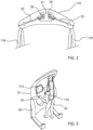
- FIG. 1A and 1B One embodiment of an autonomous ambulatory rehabilitation device 10 according to the invention is shown in perspective and schematically during a rehabilitation session on the Figures 1A and 1B , respectively seen from the front and seen from the rear.
- This device 10 comprises a mobile structure 11 assisting a patient 12 victim of a stroke in the exercise of walking along a pre-established route 13.
- the mobile structure 11 comprises a motorized carriage with automatic guidance 14, also known under the term agv, whose chassis 141 is surmounted by a gantry 15, at the top of which is mounted a horizontal beam laser sensor 126.
- This motorized laser-guided carriage 14 known per se, whose position is determined by odometry, is designed to follow the path 13 automatically, or in other words without the intervention of the therapist or the patient.
- three reflective beacons 120 have been placed at locations in the room where the precisely identifiable session is taking place.
- the route 13 defined by the therapist following the patient specifically for this session is stored in a memory of a supervision unit 125 housed inside the gantry 15.
- a USB type connector is provided on an upright of the gantry 15 to allow the therapist to connect his personal computer to the supervision unit 125 and load a new course.
- a shell 111 covers the gantry 15 and the chassis 141 of the trolley 14. It is pierced with a flared opening 112 to offer a wide field of vision to the patient 12.
- a support device 16 for the patient 12 is mounted on the gantry 15.
- This support device 16 comprises a deformable mobile bracket 115 suspended at the end of a cable 121 winding on a winch 116 fixed to the top of the gantry 15.
- the bracket 115 is formed of a platform 21 carrying two independent omnidirectional telescopic arms 22, 23, and preferably with holonomic movement, each actuated by a separate motor 24 or 25.
- a double strap 118 is fixed to each of the arms 22 and 23.
- the ends of each double strap 118 are connected to a harness harness 119 enclosing the pelvis of the patient 12.
- the support harness 119 can be moved up or down, so as to reduce or on the contrary increase the weight supported by the legs of the patient 12, by winding or unwinding the cable 121 of the winch 116.
- the position of the cable 121 is controlled as a function of the measurement of the intensity of the electric current called by the drive motor 122 of the winch 116 so as to maintain this weight, and therefore the load supported by cable 121, constant.
- the therapist may decide to reduce the support provided by the harness depending on the patient's progress.
- the actuation of the jib 115 and the winch is controlled by a real-time electronic controller 17 on board the structure 11, shown in dotted lines on the Figures 1A and 1B .
- the situations in which the patient is out of balance are identified by measuring the horizontal movements of the cable 121 and by detecting sudden variations in the electrical power absorbed by the drive motor 122.
- the controller 17 permanently acquires signals delivered by a position sensor making it possible to measure the position of the cable 121 and by an amperometric sensor measuring the value of the intensity of the current called by the drive motor 122 of the winch 116.
- a control signal for the actuating members of the bracket 115, and in this case the two actuating motors 24 and 25 of the arms 22 are generated by the controller 17, in order to move the straps 118 and thus act on the position of the patient's pelvis 12 to restore the patient's balance.
- the crane is also equipped with a mechatronic or optical sensor, for example, allowing the inclination of the cable to be measured relative to the vertical (not shown on this figure 1 ) whose data is used by the supervision unit 125 to determine the position of the patient's bust.
- the movement of the carriage 14 is also controlled by the on-board real-time controller 17.
- This controller 17 has a communication interface with the on-board supervision unit 125, which provides it with carriage guidance data.
- the supervision unit 125 is advantageously built around a modular software architecture, which is therefore scalable and simple to reconfigure.
- the controller 17 makes it possible to control an electric servomotor 18 rotating and directing two drive wheels with differential drive 142 mounted at the rear of the carriage 14 as a function of the control instructions received from the controller 17.
- it can also be envisaged to mount each of the driving wheels within a specific motor-steering turret, equipped with a geared motor acting on the direction of the wheel and a geared motor making it possible to drive the wheel in rotation towards the forward or backward.
- the servomotor 18 is supplied with electricity by a rechargeable battery 19, for example of the lead-acid gel or Lithium-ion type. Charging pads 110 mounted outside the chassis 141 of the carriage 14 allow the battery 19 to be recharged without dismantling it.
- a free rolling wheel 143 is mounted in the axis of the carriage which allows the structure 11 to follow small radii of curvature and to turn on itself, and facilitates advancement backwards.
- the structure 11 has a fixed gripping handle 114, allowing the patient 12 to adjust the instantaneous speed of the carriage 14 on the path 13.
- This handle 114 is advantageously equipped with force sensors (not shown on the Figures 1A and 1B ) measuring the intensity of the efforts exerted on it by a hand of the patient 12, connected to an interface of the controller 17.
- the patient just needs to squeeze the handle 114 tighter to increase the speed of movement of the structure, or on the contrary to release the pressure on the handle to slow down.
- the controller 17 is programmed so that the speed of movement of the patient is substantially proportional to the intensity of the tightening he exerts on the handle.
- the patient can thus simply adapt the speed of execution of each step according to their ability to walk. He can also respond to requests from the therapist who asks him to speed up on certain portions of the route.
- the controller 17 automatically controls the stopping of the trolley if the analysis of the signals delivered by the force sensors fitted to the handle 114 reveals that the patient suddenly and strongly squeezed the handle. Indeed, if he loses his balance, the patient will grab the handle reflexively.
- the shell 111 carries a display console 113 which provides the patient 12 with information on his progress and performance, which to a certain extent gives a playful aspect to the rehabilitation session, and makes it possible to encourage the patient and/or or to strengthen motivation.
- the information returned by the console 113 is for example the forward speed, the trajectory, the amplitude of the strides, the contact forces, etc.
- the therapist can also use this console as a control console, in order to adjust certain parameters of the session.
- safety devices such as for example a laser scanner, intended to prevent a shock with an object or a person, and to alert the therapist when a shock is imminent are provided.
- a shock with an object or a person
- the carriage gradually slows down.
- the trolley stops automatically.
- FIG. 3 is a detailed view of another example of an ambulatory rehabilitation device 31 according to the invention, constituting a variant of the embodiment detailed previously, allowing the patient to take control of the automatically guided trolley and to move freely in the piece.
- This device 31 has a structure identical to structure 11, also advantageously equipped with a second fixed gripping handle 33 instrumented with force sensors.
- multi-axis force sensors are arranged in sufficient number and in a suitable arrangement on each handle in order to allow measurement of the direction and intensity of the forces exerted on each of the handles by either of the patient's hands 32.
- force feedback handles also called kinesthetic handles or haptic handles
- force feedback handles may in particular be force feedback handles containing an electric motor offering resistance to the rotation of an outer ring manipulated by the patient.
- the patient can vary the advance speed of the cart along a preestablished path by grasping one or the other of the handles 114 and 32.
- the patient 32 controls both the speed of advance and the direction of the carriage 34, and can thus move autonomously in the room.
- the patient 32 then simply has to exert an asymmetrical action on the handles 114 and 33, more sustained at the level of the handle located on the side towards which a turn must be made. initiated.
- the cart When the patient releases either handle, the cart automatically switches to auto-guidance mode.
- the device 31 then automatically moves by the shortest path to a position on the pre-established route, before resuming the course layout.
- the ambulatory rehabilitation device is permanently controlled manually by the patient, and that it stops, or that it is programmed to progress in a straight line, when the patient releases the 'one of the handles.
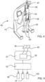
- the automatic guidance of the carriage 41 of the rehabilitation device 40 is operated using an estimate of the patient's gait 42, which is interpreted as a reflection of the movement intentions of the patient.
- This estimation of the patient's gait is based on the determination of data representative of this gait. It is obtained by real-time simulation of the dynamic behavior of a virtual mannequin representing the patient 42, based in particular on a digital reconstruction of the posture of the patient 42.
- the patient is instrumented with a limited number of sensors.
- the data provided by the inertial units 44 and 45 concerning the position and movement of the patient's pelvis and feet are collected regularly by the supervision module 51. These data are used within this supervision module by a software application 52 based on dynamic modeling of the virtual mannequin representing the patient to animate this virtual mannequin.
- the virtual digital mannequin model implemented in this embodiment of the invention is constructed by coupling a kinematic model of the skeleton with 45 degrees of freedom constructed around a tree-like chain of rigid elements in joint abutment, with a biomechanical model taking into account anthropometric parameters such as the sex, age, and size of the patient, and integrating parameters specific to the patient's pathology, making it possible to assign an envelope, or skin, to the mannequin and to manage its interaction with the external environment.
- the biomechanical model used for determining the data representative of the patient's gait takes into account the stage of rehabilitation and/or the physical condition of the patient. -this.
- the efforts exerted by the patient on the device 40 are calculated within the software application 52 and optimization strategies by quadratic criterion, consisting for example of minimizing muscular fatigue, are applied to manage the balance of the mannequin in a manner reflex and generate instructions transmitted to the controller 53 controlling the actuation of the arms of the deformable mobile jib 46 and/or the winch 47.
- the application 52 also automatically determines data representative of the patient's gait from which the patient's intention to change direction, or to speed up or slow down, for example, is extracted. It then transmits a guidance instruction including directional data and speed data to the controller 53, which in turn controls the motor for actuating the drive wheels of the carriage 41 accordingly.
- the structure of the ambulatory rehabilitation device 40 therefore moves transparently for the patient without him needing to interact directly with it.
- the software application 52 also advantageously makes it possible to monitor the patient's posture by calculating data representative of the patient's posture, and to identify if the patient is in a state of patient imbalance, by comparing this data to a base of predetermined reference data.
Landscapes
- Health & Medical Sciences (AREA)
- Epidemiology (AREA)
- Pain & Pain Management (AREA)
- Physical Education & Sports Medicine (AREA)
- Rehabilitation Therapy (AREA)
- Life Sciences & Earth Sciences (AREA)
- Animal Behavior & Ethology (AREA)
- General Health & Medical Sciences (AREA)
- Public Health (AREA)
- Veterinary Medicine (AREA)
- Rehabilitation Tools (AREA)
- Manipulator (AREA)
Claims (10)
- Ambulante Rehabilitationsvorrichtung (10; 31; 40), die eine mobile Assistenzstruktur (11) eines Individuums bei der Ausübung von mindestens einer Gehbewegung auf dem Boden umfasst, aufweisend Stützmittel des Individuums, die ein Stützgeschirr (119) umfassen, das imstande ist, mindestens einen Abschnitt des Rumpfs des Individuums, vorzugsweise einen Abschnitt des Beckens des Individuums, zu umschließen, dadurch gekennzeichnet, dass die bewegliche Struktur (11) einen motorisierten fahrerlosen Wagen mit automatischer Führung (14; 34; 41) umfasst, wobei der Wagen konfiguriert ist, um sich auf dem Boden zu verlagern,
und dass sie umfasst:- Sammelmittel einer Vielzahl von Informationen, die für die Position und die Verlagerung von mindestens einem Abschnitt des Rumpfs und/oder von mindestens einem Abschnitt jedes Fußes des Individuums repräsentativ sind;- Bestimmungsmittel einer repräsentativen Angabe des Gangs des Individuums in Abhängigkeit von der Vielzahl von Informationen; wobei die Mittel eine dynamische Modellierung einer virtuellen Person umfassen, die das Individuum darstellt, um diese virtuelle Person auf der Basis einer digitalen Rekonstruktion der Haltung des Individuums zu bewegen; und- automatische Führungsmittel des Wagens (41), umfassend Steuerungsmittel der Betätigungsmittel mindestens eines Antriebsrades (142) des Wagens (41) in Abhängigkeit von der repräsentativen Angabe des Gangs des Individuums. - Ambulante Rehabilitationsvorrichtung nach Anspruch 1, dadurch gekennzeichnet, dass das Geschirr (119) mit einem verformbaren Halter (115) fest verbunden ist, der in Bezug auf den Rahmen der Struktur (11) beweglich angebracht ist und mindestens einen omnidirektionalen Arm (22; 23) umfasst, der über einen Verbindungsgurt (118) mit dem Geschirr (119) fest verbunden ist, wobei der verformbare Halter (115) zwei Arme (22; 23) umfasst, wobei jeder der Arme (22; 23) von einem unterschiedlichen Motor (24; 25) betätigt wird.
- Ambulante Rehabilitationsvorrichtung nach einem der Ansprüche 1 bis 2, dadurch gekennzeichnet, dass der verformbare Halter (115) an einem Ende eines Kabels (121) einer Winde (116) befestigt ist.
- Ambulante Rehabilitationsvorrichtung nach Anspruch 3, dadurch gekennzeichnet, dass sie Kontrollmittel des Gleichgewichts des Individuums umfasst, die auf einen Betätigungsmotor (122) der Winde (116) und/oder auf den verformbaren Halter (115) wirken, umfassend Detektionsmittel einer Schwankung der von dem Motor (122) aufgenommenen elektrischen Leistung und Messmittel einer horizontalen Verlagerung des Kabels (121).
- Ambulante Rehabilitationsvorrichtung nach einem der Ansprüche 1 bis 4, dadurch gekennzeichnet, dass sie umfasst:- Mittel zum Erhalten von mindestens einer Information, die für die Stärke und/oder die Richtung der von dem Individuum auf ein mit der Struktur (11) fest verbundenes Greifelement (114, 33) ausgeübten Kraft repräsentativ ist;- Mittel zum Ausgeben eines Signals, welches die Information(en) umfasst,- Mittel zum Erzeugen eines Änderungs-Schwellenwerts der Verlagerungsgeschwindigkeit und/oder der Richtung des Wagens (14; 34; 41) auf der Basis des ausgegebenen Signals.
- Ambulante Rehabilitationsvorrichtung nach Anspruch 5, dadurch gekennzeichnet, dass sie automatische Führungsmittel des Wagens (14; 34; 41) umfasst, umfassend Steuerungsmittel der Betätigungsmittel mindestens eines Antriebsrades (142) des Wagens in Abhängigkeit von einer vorher festgelegten Verlagerungsgeschwindigkeit und von einer vorher festgelegten Richtung des Wagens (14; 34; 41), die der Position des Wagens (14; 34; 41) zugeordnet sind, und von dem Änderungs-Schwellenwert.
- Ambulante Rehabilitationsvorrichtung nach Anspruch 6, wenn er von Anspruch 4 abhängt, dadurch gekennzeichnet, dass sie Identifizierungsmittel eines Ungleichgewichtszustands des Individuums umfasst, die derart eingerichtet sind, dass sie die Kontrollmittel des Gleichgewichts aktivieren können, die Vergleichsmittel des oder der von dem/den Greifmittel/n (114, 33) bereitgestellten Signals/Signale mit mindestens einem vorher festgelegten Referenzsignal umfassen.
- Ambulante Rehabilitationsvorrichtung nach Anspruch 4, dadurch gekennzeichnet, dass sie umfasst:- Bestimmungsmittel einer für die Haltung des Individuums repräsentativen Angabe in Abhängigkeit von der Vielzahl von Informationen; und- Identifizierungsmittel eines Ungleichgewichtszustands des Individuums, die derart eingerichtet sind, dass sie die Kontrollmittel des Gleichgewichts aktivieren können, die Vergleichsmittel der Angabe mit mindestens einer vorher festgelegten Angabe umfassen.
- Ambulante Rehabilitationsvorrichtung nach einem der Ansprüche 1 bis 8, dadurch gekennzeichnet, dass die Bestimmungsmittel der repräsentativen Angabe des Gangs des Individuums derart konfiguriert sind, dass sie für die Bestimmung der Angabe mindestens einen für das Individuum spezifischen Parameter berücksichtigen können, der zu der Gruppe gehört, die umfasst:- anthropometrische Angabe;- Pathologie des Individuums;- Rehabilitationsstadium des Individuums;- physische Kondition des Individuums.
- Ambulante Rehabilitationsvorrichtung nach einem der Ansprüche 1 bis 9, dadurch gekennzeichnet, dass die Mittel zum Erhalten der Vielzahl von Informationen eine Messvorrichtung umfassen, die zu der Gruppe gehört, die mindestens umfasst:- Trägheitszentrale (44; 45);- Kraftsensor;- optische Sensorvorrichtung.
Priority Applications (1)
| Application Number | Priority Date | Filing Date | Title |
|---|---|---|---|
| EP16186762.7A EP3132786A1 (de) | 2011-02-10 | 2012-02-10 | Vorrichtung für die selbstständige ambulante rehabilitation |
Applications Claiming Priority (2)
| Application Number | Priority Date | Filing Date | Title |
|---|---|---|---|
| FR1151065A FR2971419B1 (fr) | 2011-02-10 | 2011-02-10 | Dispositif de reeducation ambulatoire autonome |
| PCT/FR2012/050297 WO2012107700A2 (fr) | 2011-02-10 | 2012-02-10 | Dispositif de rééducation ambulatoire autonome |
Related Child Applications (2)
| Application Number | Title | Priority Date | Filing Date |
|---|---|---|---|
| EP16186762.7A Division-Into EP3132786A1 (de) | 2011-02-10 | 2012-02-10 | Vorrichtung für die selbstständige ambulante rehabilitation |
| EP16186762.7A Division EP3132786A1 (de) | 2011-02-10 | 2012-02-10 | Vorrichtung für die selbstständige ambulante rehabilitation |
Publications (3)
| Publication Number | Publication Date |
|---|---|
| EP2672944A2 EP2672944A2 (de) | 2013-12-18 |
| EP2672944B1 EP2672944B1 (de) | 2019-10-30 |
| EP2672944B2 true EP2672944B2 (de) | 2024-06-26 |
Family
ID=45833456
Family Applications (2)
| Application Number | Title | Priority Date | Filing Date |
|---|---|---|---|
| EP16186762.7A Withdrawn EP3132786A1 (de) | 2011-02-10 | 2012-02-10 | Vorrichtung für die selbstständige ambulante rehabilitation |
| EP12708903.5A Active EP2672944B2 (de) | 2011-02-10 | 2012-02-10 | Vorrichtung für autonomes umtrainieren beim gehen |
Family Applications Before (1)
| Application Number | Title | Priority Date | Filing Date |
|---|---|---|---|
| EP16186762.7A Withdrawn EP3132786A1 (de) | 2011-02-10 | 2012-02-10 | Vorrichtung für die selbstständige ambulante rehabilitation |
Country Status (4)
| Country | Link |
|---|---|
| EP (2) | EP3132786A1 (de) |
| DK (1) | DK2672944T4 (de) |
| FR (2) | FR2971419B1 (de) |
| WO (1) | WO2012107700A2 (de) |
Families Citing this family (15)
| Publication number | Priority date | Publication date | Assignee | Title |
|---|---|---|---|---|
| US10342461B2 (en) | 2007-10-15 | 2019-07-09 | Alterg, Inc. | Method of gait evaluation and training with differential pressure system |
| WO2014153201A1 (en) | 2013-03-14 | 2014-09-25 | Alterg, Inc. | Method of gait evaluation and training with differential pressure system |
| PL2730266T3 (pl) * | 2012-11-09 | 2017-02-28 | Hocoma Ag | Urządzenie do treningu chodu |
| WO2014138281A1 (en) | 2013-03-05 | 2014-09-12 | Alterg, Inc. | Monocolumn unweighting systems |
| US10265565B2 (en) | 2013-03-14 | 2019-04-23 | Alterg, Inc. | Support frame and related unweighting system |
| US10493309B2 (en) | 2013-03-14 | 2019-12-03 | Alterg, Inc. | Cantilevered unweighting systems |
| RU2539164C1 (ru) * | 2013-11-26 | 2015-01-10 | Федеральное государственное бюджетное учреждение "Новокузнецкий научно-практический центр медико-социальной экспертизы и реабилитации инвалидов" Министерства труда и социальной защиты Российской Федерации | Способ восстановительного лечения пациентов с позвоночно-спинномозговой травмой |
| EP2881008A1 (de) * | 2013-12-09 | 2015-06-10 | Universiteit Twente | Lauftrainingsvorrichtung und ihre Verwendung |
| KR102335610B1 (ko) * | 2014-07-09 | 2021-12-06 | 호코마 아게 | 보행 훈련 장치 |
| US20170225322A1 (en) * | 2014-08-08 | 2017-08-10 | Panasonic Corporation | Movement assistance device |
| FR3039394B1 (fr) * | 2015-07-31 | 2021-03-19 | Ba Healthcare | Dispositif de reeducation ambulatoire autonome |
| FR3039449A1 (fr) * | 2015-07-31 | 2017-02-03 | Rise Ba | Robot collaboratif sur chariot autoguide assurant un soutien de l'operateur |
| IT201700023145A1 (it) * | 2017-03-01 | 2018-09-01 | Paolo Liuti | Attrezzatura elettro-meccanica di ausilio per il sollevamento e lo spostamento guidato di carichi |
| US11957954B2 (en) | 2017-10-18 | 2024-04-16 | Alterg, Inc. | Gait data collection and analytics system and methods for operating unweighting training systems |
| CN110613587B (zh) * | 2019-10-21 | 2021-11-16 | 漫步者(天津)康复设备有限公司 | 一种配重式下肢康复机器人 |
Citations (2)
| Publication number | Priority date | Publication date | Assignee | Title |
|---|---|---|---|---|
| US20090298653A1 (en) † | 2007-02-10 | 2009-12-03 | Roy Rodetsky | Powered mobile lifting, gait training and omnidirectional rolling apparatus and method |
| CN101862256A (zh) † | 2010-06-13 | 2010-10-20 | 上海交通大学 | 车载移动式助走外骨骼康复机器人 |
Family Cites Families (8)
| Publication number | Priority date | Publication date | Assignee | Title |
|---|---|---|---|---|
| WO1998041182A1 (fr) * | 1997-03-17 | 1998-09-24 | Hitachi, Ltd. | Dispositif d'aide a la marche |
| CA2302061A1 (en) * | 2000-03-23 | 2001-09-23 | Medi-Man Rehabilitation Products Inc. | Mobility assisting device and method |
| IE82873B1 (en) * | 2001-03-16 | 2003-05-14 | Haptica Ltd | A method and system for assisting an operator to manoeuvre a vehicle in a confined space |
| JP2003047635A (ja) * | 2001-08-06 | 2003-02-18 | Kochi Univ Of Technology | 歩行訓練機 |
| DE10318929B3 (de) * | 2003-04-26 | 2004-08-05 | Fraunhofer-Gesellschaft zur Förderung der angewandten Forschung e.V. | Mobile Gehhilfe-Vorrichtung |
| JP2005279009A (ja) * | 2004-03-30 | 2005-10-13 | Fatec:Kk | 歩行支援装置 |
| WO2006014533A2 (en) * | 2004-07-07 | 2006-02-09 | Home Guardian Llc | Instrumented mobility assistance device |
| JP2009195636A (ja) * | 2008-02-25 | 2009-09-03 | Tokai Univ | 歩行訓練用転倒防止装置、及び歩行支援装置 |
-
2011
- 2011-02-10 FR FR1151065A patent/FR2971419B1/fr active Active
-
2012
- 2012-02-10 WO PCT/FR2012/050297 patent/WO2012107700A2/fr not_active Ceased
- 2012-02-10 EP EP16186762.7A patent/EP3132786A1/de not_active Withdrawn
- 2012-02-10 DK DK12708903.5T patent/DK2672944T4/da active
- 2012-02-10 EP EP12708903.5A patent/EP2672944B2/de active Active
-
2014
- 2014-03-26 FR FR1452546A patent/FR3002437B1/fr not_active Expired - Fee Related
Patent Citations (2)
| Publication number | Priority date | Publication date | Assignee | Title |
|---|---|---|---|---|
| US20090298653A1 (en) † | 2007-02-10 | 2009-12-03 | Roy Rodetsky | Powered mobile lifting, gait training and omnidirectional rolling apparatus and method |
| CN101862256A (zh) † | 2010-06-13 | 2010-10-20 | 上海交通大学 | 车载移动式助走外骨骼康复机器人 |
Non-Patent Citations (1)
| Title |
|---|
| Proceedings of the 2005 IEEE. 9th International Conference on Rehabilitation Robotics 28.06 -01:07-.2005 Chicago IL USA, pages 241-246 † |
Also Published As
| Publication number | Publication date |
|---|---|
| WO2012107700A2 (fr) | 2012-08-16 |
| EP2672944B1 (de) | 2019-10-30 |
| DK2672944T3 (da) | 2020-02-03 |
| EP2672944A2 (de) | 2013-12-18 |
| FR2971419A1 (fr) | 2012-08-17 |
| FR2971419B1 (fr) | 2014-05-09 |
| EP3132786A1 (de) | 2017-02-22 |
| WO2012107700A3 (fr) | 2013-02-28 |
| FR3002437B1 (fr) | 2015-03-13 |
| DK2672944T4 (da) | 2024-08-05 |
| FR3002437A1 (fr) | 2014-08-29 |
Similar Documents
| Publication | Publication Date | Title |
|---|---|---|
| EP2672944B2 (de) | Vorrichtung für autonomes umtrainieren beim gehen | |
| JP4019119B2 (ja) | パーキンソン症候群患者用歩行支援機 | |
| JP6941058B2 (ja) | 支持−運動機構の機能障害を伴うユーザーのための歩行補助デバイス | |
| US20220110818A1 (en) | Robotic rollator walker with automated power drive | |
| CN112261971B (zh) | 步态控制移动性装置 | |
| CN111407590B (zh) | 一种上下肢训练装置、系统及方法 | |
| CN108837430A (zh) | 一种多功能人体平衡评测训练系统 | |
| Blouin et al. | Characterization of the immediate effect of a training session on a manual wheelchair simulator with Haptic biofeedback: Towards more effective propulsion | |
| US20230381592A1 (en) | Neurological rehabilitation system | |
| Cooper et al. | Virtual reality and computer-enhanced training applied to wheeled mobility: an overview of work in Pittsburgh | |
| WO2021178425A1 (en) | Hybrid wheelchair | |
| JP3528462B2 (ja) | 歩行訓練装置 | |
| KR101815989B1 (ko) | 전방착용 기립보조로봇 | |
| KR101476507B1 (ko) | 휠체어 제어방법 및 이를 이용한 이동과 재활을 위한 부하 선택형 휠체어 | |
| KR101814732B1 (ko) | 기립보조장치 및 이를 포함하는 시스템 | |
| CN111053679A (zh) | 步行支持系统 | |
| KR101800557B1 (ko) | 파킨슨병 환자용 보행보조장치 | |
| Khalili et al. | Towards the development of a learning-based intention classification framework for pushrim-activated power-assisted wheelchairs | |
| JP7283217B2 (ja) | 歩幅算出システム | |
| CN115501089A (zh) | 一种助行设备及其控制方法 | |
| EP4412801B1 (de) | Verfahren zum bewegen eines exoskeletts | |
| KR101816774B1 (ko) | 전방착용 기립보조로봇 | |
| Choi et al. | Adaptive Walker: User Intention and Terrain Aware Intelligent Walker with High-Resolution Tactile and IMU Sensor | |
| JP2020062162A (ja) | 歩行支援システム | |
| Archambault et al. | Analysis of movement to develop a virtual reality powered-wheelchair simulator |
Legal Events
| Date | Code | Title | Description |
|---|---|---|---|
| PUAI | Public reference made under article 153(3) epc to a published international application that has entered the european phase |
Free format text: ORIGINAL CODE: 0009012 |
|
| 17P | Request for examination filed |
Effective date: 20130909 |
|
| AK | Designated contracting states |
Kind code of ref document: A2 Designated state(s): AL AT BE BG CH CY CZ DE DK EE ES FI FR GB GR HR HU IE IS IT LI LT LU LV MC MK MT NL NO PL PT RO RS SE SI SK SM TR |
|
| DAX | Request for extension of the european patent (deleted) | ||
| STAA | Information on the status of an ep patent application or granted ep patent |
Free format text: STATUS: EXAMINATION IS IN PROGRESS |
|
| 17Q | First examination report despatched |
Effective date: 20170102 |
|
| RIC1 | Information provided on ipc code assigned before grant |
Ipc: A61H 3/00 20060101AFI20190411BHEP Ipc: A61H 3/04 20060101ALI20190411BHEP |
|
| GRAP | Despatch of communication of intention to grant a patent |
Free format text: ORIGINAL CODE: EPIDOSNIGR1 |
|
| STAA | Information on the status of an ep patent application or granted ep patent |
Free format text: STATUS: GRANT OF PATENT IS INTENDED |
|
| INTG | Intention to grant announced |
Effective date: 20190619 |
|
| GRAS | Grant fee paid |
Free format text: ORIGINAL CODE: EPIDOSNIGR3 |
|
| GRAA | (expected) grant |
Free format text: ORIGINAL CODE: 0009210 |
|
| STAA | Information on the status of an ep patent application or granted ep patent |
Free format text: STATUS: THE PATENT HAS BEEN GRANTED |
|
| AK | Designated contracting states |
Kind code of ref document: B1 Designated state(s): AL AT BE BG CH CY CZ DE DK EE ES FI FR GB GR HR HU IE IS IT LI LT LU LV MC MK MT NL NO PL PT RO RS SE SI SK SM TR |
|
| REG | Reference to a national code |
Ref country code: GB Ref legal event code: FG4D Free format text: NOT ENGLISH |
|
| REG | Reference to a national code |
Ref country code: CH Ref legal event code: EP |
|
| REG | Reference to a national code |
Ref country code: AT Ref legal event code: REF Ref document number: 1195379 Country of ref document: AT Kind code of ref document: T Effective date: 20191115 |
|
| REG | Reference to a national code |
Ref country code: DE Ref legal event code: R096 Ref document number: 602012065233 Country of ref document: DE |
|
| REG | Reference to a national code |
Ref country code: IE Ref legal event code: FG4D Free format text: LANGUAGE OF EP DOCUMENT: FRENCH |
|
| REG | Reference to a national code |
Ref country code: NO Ref legal event code: T2 Effective date: 20191030 Ref country code: DK Ref legal event code: T3 Effective date: 20200130 |
|
| REG | Reference to a national code |
Ref country code: SE Ref legal event code: TRGR |
|
| REG | Reference to a national code |
Ref country code: CH Ref legal event code: PCAR Free format text: NEW ADDRESS: ROUTE DU COUTSET 18, 1485 NUVILLY (CH) |
|
| REG | Reference to a national code |
Ref country code: NL Ref legal event code: FP |
|
| REG | Reference to a national code |
Ref country code: LT Ref legal event code: MG4D |
|
| PG25 | Lapsed in a contracting state [announced via postgrant information from national office to epo] |
Ref country code: LV Free format text: LAPSE BECAUSE OF FAILURE TO SUBMIT A TRANSLATION OF THE DESCRIPTION OR TO PAY THE FEE WITHIN THE PRESCRIBED TIME-LIMIT Effective date: 20191030 Ref country code: PL Free format text: LAPSE BECAUSE OF FAILURE TO SUBMIT A TRANSLATION OF THE DESCRIPTION OR TO PAY THE FEE WITHIN THE PRESCRIBED TIME-LIMIT Effective date: 20191030 Ref country code: GR Free format text: LAPSE BECAUSE OF FAILURE TO SUBMIT A TRANSLATION OF THE DESCRIPTION OR TO PAY THE FEE WITHIN THE PRESCRIBED TIME-LIMIT Effective date: 20200131 Ref country code: BG Free format text: LAPSE BECAUSE OF FAILURE TO SUBMIT A TRANSLATION OF THE DESCRIPTION OR TO PAY THE FEE WITHIN THE PRESCRIBED TIME-LIMIT Effective date: 20200130 Ref country code: FI Free format text: LAPSE BECAUSE OF FAILURE TO SUBMIT A TRANSLATION OF THE DESCRIPTION OR TO PAY THE FEE WITHIN THE PRESCRIBED TIME-LIMIT Effective date: 20191030 Ref country code: PT Free format text: LAPSE BECAUSE OF FAILURE TO SUBMIT A TRANSLATION OF THE DESCRIPTION OR TO PAY THE FEE WITHIN THE PRESCRIBED TIME-LIMIT Effective date: 20200302 Ref country code: ES Free format text: LAPSE BECAUSE OF FAILURE TO SUBMIT A TRANSLATION OF THE DESCRIPTION OR TO PAY THE FEE WITHIN THE PRESCRIBED TIME-LIMIT Effective date: 20191030 Ref country code: LT Free format text: LAPSE BECAUSE OF FAILURE TO SUBMIT A TRANSLATION OF THE DESCRIPTION OR TO PAY THE FEE WITHIN THE PRESCRIBED TIME-LIMIT Effective date: 20191030 |
|
| PG25 | Lapsed in a contracting state [announced via postgrant information from national office to epo] |
Ref country code: HR Free format text: LAPSE BECAUSE OF FAILURE TO SUBMIT A TRANSLATION OF THE DESCRIPTION OR TO PAY THE FEE WITHIN THE PRESCRIBED TIME-LIMIT Effective date: 20191030 Ref country code: IS Free format text: LAPSE BECAUSE OF FAILURE TO SUBMIT A TRANSLATION OF THE DESCRIPTION OR TO PAY THE FEE WITHIN THE PRESCRIBED TIME-LIMIT Effective date: 20200229 Ref country code: RS Free format text: LAPSE BECAUSE OF FAILURE TO SUBMIT A TRANSLATION OF THE DESCRIPTION OR TO PAY THE FEE WITHIN THE PRESCRIBED TIME-LIMIT Effective date: 20191030 |
|
| REG | Reference to a national code |
Ref country code: DE Ref legal event code: R082 Ref document number: 602012065233 Country of ref document: DE Representative=s name: HELLMICH, WOLFGANG, DIPL.-PHYS.UNIV. DR.-ING., DE Ref country code: DE Ref legal event code: R081 Ref document number: 602012065233 Country of ref document: DE Owner name: BA HEALTHCARE, FR Free format text: FORMER OWNER: RISE BA, MORDELLES, FR Ref country code: DE Ref legal event code: R081 Ref document number: 602012065233 Country of ref document: DE Owner name: BA HEALTHCARE, FR Free format text: FORMER OWNER: BA ROBOTIC SYSTEMS GROUP, MORDELLES, FR |
|
| REG | Reference to a national code |
Ref country code: NO Ref legal event code: CHAD Owner name: BA HEALTHCARE, FR |
|
| PG25 | Lapsed in a contracting state [announced via postgrant information from national office to epo] |
Ref country code: AL Free format text: LAPSE BECAUSE OF FAILURE TO SUBMIT A TRANSLATION OF THE DESCRIPTION OR TO PAY THE FEE WITHIN THE PRESCRIBED TIME-LIMIT Effective date: 20191030 |
|
| REG | Reference to a national code |
Ref country code: CH Ref legal event code: NV Representative=s name: BUGNION S.A., CH Ref country code: CH Ref legal event code: PUE Owner name: BA HEALTHCARE, FR Free format text: FORMER OWNER: RISE BA, FR |
|
| REG | Reference to a national code |
Ref country code: GB Ref legal event code: 732E Free format text: REGISTERED BETWEEN 20200702 AND 20200708 Ref country code: DE Ref legal event code: R026 Ref document number: 602012065233 Country of ref document: DE |
|
| PG25 | Lapsed in a contracting state [announced via postgrant information from national office to epo] |
Ref country code: CZ Free format text: LAPSE BECAUSE OF FAILURE TO SUBMIT A TRANSLATION OF THE DESCRIPTION OR TO PAY THE FEE WITHIN THE PRESCRIBED TIME-LIMIT Effective date: 20191030 Ref country code: RO Free format text: LAPSE BECAUSE OF FAILURE TO SUBMIT A TRANSLATION OF THE DESCRIPTION OR TO PAY THE FEE WITHIN THE PRESCRIBED TIME-LIMIT Effective date: 20191030 Ref country code: EE Free format text: LAPSE BECAUSE OF FAILURE TO SUBMIT A TRANSLATION OF THE DESCRIPTION OR TO PAY THE FEE WITHIN THE PRESCRIBED TIME-LIMIT Effective date: 20191030 |
|
| PLBI | Opposition filed |
Free format text: ORIGINAL CODE: 0009260 |
|
| PLAX | Notice of opposition and request to file observation + time limit sent |
Free format text: ORIGINAL CODE: EPIDOSNOBS2 |
|
| REG | Reference to a national code |
Ref country code: AT Ref legal event code: MK05 Ref document number: 1195379 Country of ref document: AT Kind code of ref document: T Effective date: 20191030 |
|
| REG | Reference to a national code |
Ref country code: BE Ref legal event code: HC Owner name: BA ROBOTIC SYSTEMS GROUP; FR Free format text: DETAILS ASSIGNMENT: CHANGE OF OWNER(S), CHANGEMENT DE NOM DU PROPRIETAIRE; FORMER OWNER NAME: RISE BA Effective date: 20200603 Ref country code: BE Ref legal event code: PD Owner name: BA HEALTHCARE; FR Free format text: DETAILS ASSIGNMENT: CHANGE OF OWNER(S), CESSION; FORMER OWNER NAME: BA ROBOTIC SYSTEMS GROUP Effective date: 20200603 |
|
| PG25 | Lapsed in a contracting state [announced via postgrant information from national office to epo] |
Ref country code: SM Free format text: LAPSE BECAUSE OF FAILURE TO SUBMIT A TRANSLATION OF THE DESCRIPTION OR TO PAY THE FEE WITHIN THE PRESCRIBED TIME-LIMIT Effective date: 20191030 Ref country code: SK Free format text: LAPSE BECAUSE OF FAILURE TO SUBMIT A TRANSLATION OF THE DESCRIPTION OR TO PAY THE FEE WITHIN THE PRESCRIBED TIME-LIMIT Effective date: 20191030 |
|
| 26 | Opposition filed |
Opponent name: PTR ROBOTS APS Effective date: 20200729 |
|
| REG | Reference to a national code |
Ref country code: NL Ref legal event code: HC Owner name: BA ROBOTIC SYSTEMS GROUP; FR Free format text: DETAILS ASSIGNMENT: CHANGE OF OWNER(S), CHANGE OF OWNER(S) NAME; FORMER OWNER NAME: RISE BA Effective date: 20200819 Ref country code: NL Ref legal event code: PD Owner name: BA HEALTHCARE; FR Free format text: DETAILS ASSIGNMENT: CHANGE OF OWNER(S), ASSIGNMENT; FORMER OWNER NAME: BA ROBOTIC SYSTEMS GROUP Effective date: 20200819 |
|
| PG25 | Lapsed in a contracting state [announced via postgrant information from national office to epo] |
Ref country code: MC Free format text: LAPSE BECAUSE OF FAILURE TO SUBMIT A TRANSLATION OF THE DESCRIPTION OR TO PAY THE FEE WITHIN THE PRESCRIBED TIME-LIMIT Effective date: 20191030 Ref country code: LU Free format text: LAPSE BECAUSE OF NON-PAYMENT OF DUE FEES Effective date: 20200210 |
|
| PG25 | Lapsed in a contracting state [announced via postgrant information from national office to epo] |
Ref country code: AT Free format text: LAPSE BECAUSE OF FAILURE TO SUBMIT A TRANSLATION OF THE DESCRIPTION OR TO PAY THE FEE WITHIN THE PRESCRIBED TIME-LIMIT Effective date: 20191030 Ref country code: SI Free format text: LAPSE BECAUSE OF FAILURE TO SUBMIT A TRANSLATION OF THE DESCRIPTION OR TO PAY THE FEE WITHIN THE PRESCRIBED TIME-LIMIT Effective date: 20191030 |
|
| PLBB | Reply of patent proprietor to notice(s) of opposition received |
Free format text: ORIGINAL CODE: EPIDOSNOBS3 |
|
| PG25 | Lapsed in a contracting state [announced via postgrant information from national office to epo] |
Ref country code: IE Free format text: LAPSE BECAUSE OF NON-PAYMENT OF DUE FEES Effective date: 20200210 |
|
| RAP2 | Party data changed (patent owner data changed or rights of a patent transferred) |
Owner name: BA HEALTHCARE |
|
| PG25 | Lapsed in a contracting state [announced via postgrant information from national office to epo] |
Ref country code: MT Free format text: LAPSE BECAUSE OF FAILURE TO SUBMIT A TRANSLATION OF THE DESCRIPTION OR TO PAY THE FEE WITHIN THE PRESCRIBED TIME-LIMIT Effective date: 20191030 Ref country code: CY Free format text: LAPSE BECAUSE OF FAILURE TO SUBMIT A TRANSLATION OF THE DESCRIPTION OR TO PAY THE FEE WITHIN THE PRESCRIBED TIME-LIMIT Effective date: 20191030 Ref country code: TR Free format text: LAPSE BECAUSE OF FAILURE TO SUBMIT A TRANSLATION OF THE DESCRIPTION OR TO PAY THE FEE WITHIN THE PRESCRIBED TIME-LIMIT Effective date: 20191030 |
|
| PG25 | Lapsed in a contracting state [announced via postgrant information from national office to epo] |
Ref country code: MK Free format text: LAPSE BECAUSE OF FAILURE TO SUBMIT A TRANSLATION OF THE DESCRIPTION OR TO PAY THE FEE WITHIN THE PRESCRIBED TIME-LIMIT Effective date: 20191030 |
|
| APAH | Appeal reference modified |
Free format text: ORIGINAL CODE: EPIDOSCREFNO |
|
| APBM | Appeal reference recorded |
Free format text: ORIGINAL CODE: EPIDOSNREFNO |
|
| APBP | Date of receipt of notice of appeal recorded |
Free format text: ORIGINAL CODE: EPIDOSNNOA2O |
|
| APBM | Appeal reference recorded |
Free format text: ORIGINAL CODE: EPIDOSNREFNO |
|
| APBP | Date of receipt of notice of appeal recorded |
Free format text: ORIGINAL CODE: EPIDOSNNOA2O |
|
| PLAB | Opposition data, opponent's data or that of the opponent's representative modified |
Free format text: ORIGINAL CODE: 0009299OPPO |
|
| R26 | Opposition filed (corrected) |
Opponent name: PTR ROBOTS APS Effective date: 20200729 |
|
| APBQ | Date of receipt of statement of grounds of appeal recorded |
Free format text: ORIGINAL CODE: EPIDOSNNOA3O |
|
| APBQ | Date of receipt of statement of grounds of appeal recorded |
Free format text: ORIGINAL CODE: EPIDOSNNOA3O |
|
| APBU | Appeal procedure closed |
Free format text: ORIGINAL CODE: EPIDOSNNOA9O |
|
| PUAH | Patent maintained in amended form |
Free format text: ORIGINAL CODE: 0009272 |
|
| STAA | Information on the status of an ep patent application or granted ep patent |
Free format text: STATUS: PATENT MAINTAINED AS AMENDED |
|
| 27A | Patent maintained in amended form |
Effective date: 20240626 |
|
| AK | Designated contracting states |
Kind code of ref document: B2 Designated state(s): AL AT BE BG CH CY CZ DE DK EE ES FI FR GB GR HR HU IE IS IT LI LT LU LV MC MK MT NL NO PL PT RO RS SE SI SK SM TR |
|
| REG | Reference to a national code |
Ref country code: DE Ref legal event code: R102 Ref document number: 602012065233 Country of ref document: DE |
|
| REG | Reference to a national code |
Ref country code: DK Ref legal event code: T4 Effective date: 20240731 |
|
| REG | Reference to a national code |
Ref country code: SE Ref legal event code: RPEO |
|
| REG | Reference to a national code |
Ref country code: NL Ref legal event code: FP |
|
| PGFP | Annual fee paid to national office [announced via postgrant information from national office to epo] |
Ref country code: NL Payment date: 20250211 Year of fee payment: 14 |
|
| PGFP | Annual fee paid to national office [announced via postgrant information from national office to epo] |
Ref country code: DE Payment date: 20250211 Year of fee payment: 14 |
|
| PGFP | Annual fee paid to national office [announced via postgrant information from national office to epo] |
Ref country code: DK Payment date: 20250213 Year of fee payment: 14 |
|
| PGFP | Annual fee paid to national office [announced via postgrant information from national office to epo] |
Ref country code: SE Payment date: 20250214 Year of fee payment: 14 |
|
| PGFP | Annual fee paid to national office [announced via postgrant information from national office to epo] |
Ref country code: NO Payment date: 20250219 Year of fee payment: 14 |
|
| PGFP | Annual fee paid to national office [announced via postgrant information from national office to epo] |
Ref country code: BE Payment date: 20250211 Year of fee payment: 14 Ref country code: CH Payment date: 20250301 Year of fee payment: 14 |
|
| PGFP | Annual fee paid to national office [announced via postgrant information from national office to epo] |
Ref country code: FR Payment date: 20250224 Year of fee payment: 14 |
|
| PGFP | Annual fee paid to national office [announced via postgrant information from national office to epo] |
Ref country code: IT Payment date: 20250211 Year of fee payment: 14 Ref country code: GB Payment date: 20250214 Year of fee payment: 14 |