EP2672025B1 - Hybrid construction machine - Google Patents
Hybrid construction machine Download PDFInfo
- Publication number
- EP2672025B1 EP2672025B1 EP12742161.8A EP12742161A EP2672025B1 EP 2672025 B1 EP2672025 B1 EP 2672025B1 EP 12742161 A EP12742161 A EP 12742161A EP 2672025 B1 EP2672025 B1 EP 2672025B1
- Authority
- EP
- European Patent Office
- Prior art keywords
- swing
- hydraulic
- torque
- motor
- electric motor
- Prior art date
- Legal status (The legal status is an assumption and is not a legal conclusion. Google has not performed a legal analysis and makes no representation as to the accuracy of the status listed.)
- Active
Links
- 238000010276 construction Methods 0.000 title claims description 66
- 230000007423 decrease Effects 0.000 claims description 14
- 239000003990 capacitor Substances 0.000 description 49
- 238000010586 diagram Methods 0.000 description 30
- 239000010720 hydraulic oil Substances 0.000 description 16
- 238000006243 chemical reaction Methods 0.000 description 15
- 238000010248 power generation Methods 0.000 description 7
- 238000009412 basement excavation Methods 0.000 description 4
- 238000006073 displacement reaction Methods 0.000 description 3
- 238000009499 grossing Methods 0.000 description 3
- 230000001965 increasing effect Effects 0.000 description 3
- 230000008929 regeneration Effects 0.000 description 3
- 238000011069 regeneration method Methods 0.000 description 3
- 239000004576 sand Substances 0.000 description 3
- 238000007796 conventional method Methods 0.000 description 2
- 238000007599 discharging Methods 0.000 description 2
- 230000005611 electricity Effects 0.000 description 2
- 239000000446 fuel Substances 0.000 description 2
- 230000002265 prevention Effects 0.000 description 2
- 230000005856 abnormality Effects 0.000 description 1
- 230000001133 acceleration Effects 0.000 description 1
- 230000004913 activation Effects 0.000 description 1
- 230000006866 deterioration Effects 0.000 description 1
- 230000000694 effects Effects 0.000 description 1
- 230000002708 enhancing effect Effects 0.000 description 1
- 230000012447 hatching Effects 0.000 description 1
- 230000007935 neutral effect Effects 0.000 description 1
- 239000003921 oil Substances 0.000 description 1
- 238000013021 overheating Methods 0.000 description 1
- 230000001172 regenerating effect Effects 0.000 description 1
- 230000000087 stabilizing effect Effects 0.000 description 1
Images


Classifications
-
- E—FIXED CONSTRUCTIONS
- E02—HYDRAULIC ENGINEERING; FOUNDATIONS; SOIL SHIFTING
- E02F—DREDGING; SOIL-SHIFTING
- E02F9/00—Component parts of dredgers or soil-shifting machines, not restricted to one of the kinds covered by groups E02F3/00 - E02F7/00
- E02F9/20—Drives; Control devices
- E02F9/22—Hydraulic or pneumatic drives
-
- E—FIXED CONSTRUCTIONS
- E02—HYDRAULIC ENGINEERING; FOUNDATIONS; SOIL SHIFTING
- E02F—DREDGING; SOIL-SHIFTING
- E02F9/00—Component parts of dredgers or soil-shifting machines, not restricted to one of the kinds covered by groups E02F3/00 - E02F7/00
- E02F9/08—Superstructures; Supports for superstructures
- E02F9/10—Supports for movable superstructures mounted on travelling or walking gears or on other superstructures
- E02F9/12—Slewing or traversing gears
- E02F9/121—Turntables, i.e. structure rotatable about 360°
- E02F9/123—Drives or control devices specially adapted therefor
-
- E—FIXED CONSTRUCTIONS
- E02—HYDRAULIC ENGINEERING; FOUNDATIONS; SOIL SHIFTING
- E02F—DREDGING; SOIL-SHIFTING
- E02F9/00—Component parts of dredgers or soil-shifting machines, not restricted to one of the kinds covered by groups E02F3/00 - E02F7/00
- E02F9/20—Drives; Control devices
-
- E—FIXED CONSTRUCTIONS
- E02—HYDRAULIC ENGINEERING; FOUNDATIONS; SOIL SHIFTING
- E02F—DREDGING; SOIL-SHIFTING
- E02F9/00—Component parts of dredgers or soil-shifting machines, not restricted to one of the kinds covered by groups E02F3/00 - E02F7/00
- E02F9/20—Drives; Control devices
- E02F9/2025—Particular purposes of control systems not otherwise provided for
- E02F9/2037—Coordinating the movements of the implement and of the frame
-
- E—FIXED CONSTRUCTIONS
- E02—HYDRAULIC ENGINEERING; FOUNDATIONS; SOIL SHIFTING
- E02F—DREDGING; SOIL-SHIFTING
- E02F9/00—Component parts of dredgers or soil-shifting machines, not restricted to one of the kinds covered by groups E02F3/00 - E02F7/00
- E02F9/20—Drives; Control devices
- E02F9/2058—Electric or electro-mechanical or mechanical control devices of vehicle sub-units
- E02F9/2095—Control of electric, electro-mechanical or mechanical equipment not otherwise provided for, e.g. ventilators, electro-driven fans
-
- Y—GENERAL TAGGING OF NEW TECHNOLOGICAL DEVELOPMENTS; GENERAL TAGGING OF CROSS-SECTIONAL TECHNOLOGIES SPANNING OVER SEVERAL SECTIONS OF THE IPC; TECHNICAL SUBJECTS COVERED BY FORMER USPC CROSS-REFERENCE ART COLLECTIONS [XRACs] AND DIGESTS
- Y10—TECHNICAL SUBJECTS COVERED BY FORMER USPC
- Y10S—TECHNICAL SUBJECTS COVERED BY FORMER USPC CROSS-REFERENCE ART COLLECTIONS [XRACs] AND DIGESTS
- Y10S903/00—Hybrid electric vehicles, HEVS
- Y10S903/902—Prime movers comprising electrical and internal combustion motors
- Y10S903/903—Prime movers comprising electrical and internal combustion motors having energy storing means, e.g. battery, capacitor
- Y10S903/93—Conjoint control of different elements
Definitions
- the present invention relates to hybrid construction machine, and in particular, to hybrid construction machine having a swing structure such as a hydraulic excavator, such as disclosed in JP A 2010 065510 .
- a construction machine such as a hydraulic excavator employs fuel (gasoline, light oil, etc.) as the power source of its engine and drives hydraulic actuators (hydraulic motor, hydraulic cylinder, etc.) using hydraulic pressure generated by a hydraulic pump which is driven by the engine.
- fuel gasoline, light oil, etc.
- hydraulic actuators hydraulic motor, hydraulic cylinder, etc.
- the hydraulic actuators are widely used as actuators for a construction machine.
- Electric motors have some excellent features in terms of energy, such as higher energy efficiency compared to hydraulic actuators and the ability to regenerate electric energy from kinetic energy at the time of braking. The kinetic energy is released and lost as heat in the case of hydraulic actuators.
- Patent Document 1 discloses an embodiment of a hydraulic excavator having an electric motor as the actuator for driving the swing structure.
- the actuator for driving and rotating the upper swing structure of the hydraulic excavator with respect to the lower track structure is used frequently and repeats activation/stoppage and acceleration/deceleration frequently in work.
- the Patent Document 2 discloses an energy regeneration device of a hydraulic construction machine in which an electric motor is connected directly to the hydraulic motor for driving the swing structure.
- a controller determines the output torque of the electric motor based on the operation amount of the operating lever and sends an output torque command to the electric motor.
- deceleration braking
- the electric motor regenerates the kinetic energy of the swing structure into electric energy and accumulates the regenerated energy in a battery.
- the Patent Document 3 discloses a hybrid construction machine which performs output torque splitting between the hydraulic motor and the electric motor by calculating a torque command value for the electric motor using the differential pressure between the inlet side and the outlet side of the hydraulic motor for the swing driving.
- Both of the conventional techniques of the Patent Documents 2 and 3 employ an electric motor and a hydraulic motor together as the actuators for the swing driving and thereby realize operation with no feeling of strangeness even for operators accustomed to a conventional construction machine driven by a hydraulic actuator, as well as achieving energy saving with a configuration that is simple and easy to put into practical use.
- the kinetic energy of the swing structure in deceleration (braking) is regenerated by the electric motor into electric energy, which is effective from the viewpoint of energy saving.
- the hybrid hydraulic excavators described in the Patent Documents 2 and 3 solve the above problems by employing both a hydraulic motor and an electric motor and driving the swing structure by the total torque of the motors, thereby realizing operation with no feeling of strangeness even for operators accustomed to a conventional construction machine driven by a hydraulic actuator, as well as achieving energy saving with a configuration that is simple and easy to put into practical use.
- the object of the present invention which has been made in consideration of the above situation, is to provide a hybrid construction machine employing a hydraulic motor and an electric motor for the driving of the swing structure and being capable of securing satisfactory operability in the combined operation of the swing structure and other actuators irrespective of the operating status of the electric motor.
- a hybrid construction machine comprising: a prime mover; a hydraulic pump which is driven by the prime mover; a swing structure; an electric motor for driving the swing structure; a hydraulic motor for driving the swing structure, the hydraulic motor being driven by the hydraulic pump; an electrical storage device which is connected to the electric motor; a swing operating lever device which is operated for commanding the driving of the swing structure; a second hydraulic actuator which is driven by the hydraulic pump and drives a driven part other than the swing structure; a second operating lever device which is operated for commanding the driving of the second hydraulic actuator; and a control device which executes control selected from: hydraulic/electric complex swing control for driving the swing structure by total torque of the electric motor and the hydraulic motor by driving both the electric motor and the hydraulic motor when the swing operating lever device is operated; and hydraulic solo swing control for driving the swing structure by the torque of the hydraulic motor alone by driving only the hydraulic motor when the swing operating lever device is operated.
- the control device controls drive torque of the electric motor, drive torque of the hydraulic motor and driving force of the second hydraulic actuator so that the relationship between the position or the speed of the second hydraulic actuator and the swing angle or the swing speed of the swing structure when the swing operating lever device and the second operating lever device are operated at the same time during the hydraulic/electric complex swing control is substantially identical with the relationship between the position or the speed of the second hydraulic actuator and the swing angle or the swing speed of the swing structure when the swing operating lever device and the second operating lever device are operated at the same time during the hydraulic solo swing control.
- the control device controls the drive torque of the electric motor so that the ratio of the drive torque of the electric motor to the drive torque of the hydraulic motor decreases with the increase in the operation amount of the second operating lever device.
- the control device increases the drive torque of the electric motor and controls the drive torque of the hydraulic motor so as to reduce the drive torque of the hydraulic motor by an amount corresponding to the increase in the drive torque of the electric motor.
- the control device controls the driving force of the second hydraulic actuator so as to reduce the driving force of the second hydraulic actuator.
- the hybrid construction machine as described in the first aspect, wherein the second hydraulic actuator is a boom cylinder, and the second operating lever device is a boom raising operating lever device.
- the control device reduces the drive torque of the hydraulic motor by performing reduction control on the output of the hydraulic pump.
- the control device reduces the driving force of the second hydraulic actuator by performing reduction control on the output of the hydraulic pump.
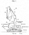
- Fig. 1 is a side view of a hybrid construction machine in accordance with a first embodiment of the present invention.
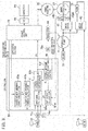
- Fig. 2 is a system configuration diagram of electric/hydraulic devices constituting the hybrid construction machine in accordance with the first embodiment of the present invention.
- Fig. 3 is a block diagram showing the system configuration and control blocks of the hybrid construction machine in accordance with the first embodiment of the present invention.
- an electrically-driven hydraulic excavator comprises a track structure 10, a swing structure 20 mounted on the track structure 10 to be rotatable, and an excavation mechanism 30 attached to the swing structure 20.
- the track structure 10 is made up of a symmetrical pair of crawlers 11 and a symmetrical pair of crawler frames 12 (shown only one each in Fig. 1 ), a pair of track hydraulic motors 13 and 14 for performing drive control of the crawlers 11 independently of one another, and a speed reduction mechanism working in conjunction with the track hydraulic motors 13 and 14.
- the swing structure 20 includes a swing frame 21, an engine 22 (as a prime mover) mounted on the swing frame 21, an assist power generation motor 23 driven by the engine 22, a swing electric motor 25, a capacitor 24 (as an electrical storage device connected to the assist power generation motor 23 and the swing electric motor 25), a speed reduction mechanism 26 for decelerating the rotation of the swing electric motor 25, etc.
- the driving force of the swing electric motor 25 is transmitted via the speed reduction mechanism 26, by which the swing structure 20 (swing frame 21) is driven and rotated with respect to the track structure 10.
- the swing structure 20 is equipped with the excavation mechanism (front device) 30.
- the excavation mechanism 30 includes a boom 31, a boom cylinder 32 for driving the boom 31, an arm 33 supported by a distal end part of the boom 31 to be rotatable around an axis, an arm cylinder 34 for driving the arm 33, a bucket 35 supported by the distal end of the arm 33 to be rotatable around an axis, a bucket cylinder 36 for driving the bucket 35, etc.
- a hydraulic system 40 for driving hydraulic actuators (such as the travel hydraulic motors 13 and 14, a swing hydraulic motor 27, the boom cylinder 32, the arm cylinder 34 and the bucket cylinder 36) is mounted on the swing frame 21 of the swing structure 20.
- the hydraulic system 40 includes a hydraulic pump 41 (see Fig. 2 ) as a hydraulic pressure source for generating the hydraulic pressure and a control valve 42 (see Fig. 2 ) for driving and controlling the actuators.
- the hydraulic pump 41 is driven by the engine 22.
- the control valve 42 controls the flow rate and the direction of the hydraulic oil supplied to the swing hydraulic motor 27 by operating a swing spool 61 (see Fig. 3 ) according to a swing operation command (hydraulic pilot signal) inputted from a swing operating lever device 72 (see Fig. 3 ).
- the control valve 42 also controls the flow rate and the direction of the hydraulic oil supplied to each of the boom cylinder 32, the arm cylinder 34, the bucket cylinder 36 and the travel hydraulic motors 13 and 14 by operating various spools according to operation commands (hydraulic pilot signals) inputted from operating lever devices for operations other than the swinging.
- An electric system of the hydraulic excavator is made up of the assist power generation motor 23, the capacitor 24, the swing electric motor 25, a power control unit 55, a main contactor 56, etc.
- the power control unit 55 includes a chopper 51, inverters 52 and 53, a smoothing capacitor 54, etc.
- the main contactor 56 includes a main relay 57, an inrush current prevention circuit 58, etc.
- the voltage of DC power supplied from the capacitor 24 is boosted by the chopper 51 to a predetermined bus voltage and is inputted to the inverter 52 (for driving the swing electric motor 25) and the inverter 53 (for driving the assist power generation motor 23).
- the smoothing capacitor 54 is used for stabilizing the bus voltage.
- the capacitor 24 is charged or discharged depending on the driving status (regenerating or power running) of the assist power generation motor 23 and the swing electric motor 25.
- a controller 80 generates control commands for the control valve 42 and the power control unit 55 by using various operation command signals, pressure signals of the swing hydraulic motor 27, an angular speed signal of the swing electric motor 25, etc. and thereby executes torque control of the swing electric motor 25, discharge flow rate control of the hydraulic pump 41, etc.
- Fig. 3 is a block diagram showing the system configuration and control blocks of the hydraulic excavator. While the system configuration of the electric/hydraulic devices shown in Fig. 3 is basically identical with that in Fig. 2 , devices, control means, control signals, etc. necessary for carrying out the swing control in accordance with the present invention are shown in detail in Fig. 3 .
- the hybrid hydraulic excavator shown in Fig. 3 is equipped with the aforementioned controller 80 and units (hydraulic-electric conversion units 74a, 74bL, 74bR and 74c and an electric-hydraulic conversion unit 75a) related to the input/output of the controller 80. These components constitute a swing control system.
- the hydraulic-electric conversion units 74a, 74bL, 74bR and 74c are implemented by pressure sensors, for example.
- the electric-hydraulic conversion unit 75a is implemented by a solenoid-operated proportional pressure-reducing valve, for example.
- the controller 80 includes a target power-running power calculation block 83a, a target power-running torque calculation block 83b, a limit gain calculation block 83c, a limit torque calculation block 83d, a torque command value calculation block 83e, a hydraulic pump power reduction control block 83f, etc.
- the hydraulic pilot signal generated according to the operator's input to the swing operating lever device 72 is converted by the hydraulic-electric conversion unit 74a into an electric signal and inputted to the limit gain calculation block 83c.
- a hydraulic pilot signal generated according to the operator's input to a boom operating lever device 78 (as an operating lever device for an operation other than the swinging) is converted by the hydraulic-electric conversion unit 74c into an electric signal and inputted to the limit gain calculation block 83c.
- Operating pressures of the swing hydraulic motor 27 are converted by the hydraulic-electric conversion units 74bR and 74bL into electric signals and inputted to the limit torque calculation block 83d.
- the torque command value calculation block 83e calculates command torque for the swing electric motor 25 as explained later and outputs a torque command EA to the power control unit 55.
- a torque reduction command EB for reducing the output torque of the hydraulic pump 41 by the torque outputted by the swing electric motor 25 is outputted from the hydraulic pump power reduction control block 83f to the electric-hydraulic conversion unit 75a.
- a hydraulic pilot signal from the electric-hydraulic conversion unit 75a is inputted to a regulator 64 which controls the discharge flow rate of the hydraulic pump 41.
- the hydraulic pilot signal generated according to the operator's input to the swing operating lever device 72 is inputted also to the control valve 42, by which the spool 61 for the swing hydraulic motor 27 is switched from its neutral position, the hydraulic oil discharged from the hydraulic pump 41 is supplied to the swing hydraulic motor 27, and consequently, the swing hydraulic motor 27 is also driven at the same time.
- the hydraulic pilot signal generated according to the operator's input to the boom operating lever device 78 is inputted also to the control valve 42, by which a spool 62 for the boom is switched and the hydraulic oil discharged from the hydraulic pump 41 is supplied to the boom cylinder 32 to drive the boom 31.
- the hydraulic pump 41 is a variable displacement pump. By the operation of the regulator 64, the tilting angle of the hydraulic pump 41 is changed, the displacement (capacity) of the hydraulic pump 41 is changed, and consequently, the discharge flow rate and the torque of the hydraulic pump 41 are changed.
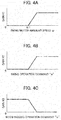
- Fig. 4 shows control gain characteristic diagrams of the controller constituting the hybrid construction machine in accordance with the first embodiment of the present invention, wherein Fig. 4(A) is a characteristic diagram of gain K1, Fig. 4(B) is a characteristic diagram of gain K2, and Fig. 4(C) is a characteristic diagram of gain K3.
- Fig. 5 is a characteristic diagram showing torque control characteristics of the hydraulic pump in the hybrid construction machine in accordance with the first embodiment of the present invention.
- Reference characters in Figs. 4 and 5 identical with those in Figs. 1 - 3 represent components identical or corresponding to those in Figs. 1 - 3 , and thus repeated explanation thereof is omitted for brevity.
- the target power-running power calculation block 83a receives the voltage value Vc of the capacitor 24 from the power control unit 55 as an input signal, compares the voltage value Vc with a preset operational threshold Vp for permitting the operation of the swing electric motor 25, and outputs an output value P.
- a positive value is outputted as the output value P.
- the electric amount is small (i.e., when the capacitor voltage Vc is lower than the operational threshold Vp)
- the output value P may be changed depending on the difference between the capacitor voltage Vc and the operational threshold Vp.
- the operational threshold Vp of the swing electric motor 25 is a voltage value of the capacitor 24 at/above which the balance between the charging and the discharging of the capacitor 24 can be maintained during the regeneration and the power running for preset operational patterns of the swing electric motor 25.
- the operational threshold Vp of the swing electric motor 25 has been set higher than the operation guarantee minimum voltage value of the capacitor 24 and lower than the operation guarantee maximum voltage value of the capacitor 24.
- the operational threshold Vp may be set at 120 V when the operation guarantee minimum voltage value of the capacitor 24 is 100 V.
- the capacitor voltage Vc tends to fall below the operation guarantee minimum voltage of the capacitor 24 since the driving of the swing electric motor 25 is possible (permitted) as long as the capacitor voltage Vc is 100 V or higher.
- the operation of the swing electric motor 25 is permitted only above the voltage value at which the balance between charging and the discharging of the capacitor 24 can be maintained.
- the target power-running torque calculation block 83b receives the angular speed signal ⁇ of the swing electric motor 25 from the power control unit 55 and the aforementioned output value P from the target power-running power calculation block 83a as input signals, calculates target power-running torque T by dividing the output value P by the angular speed signal ⁇ , and outputs the calculated target power-running torque T.
- the value of the target power-running torque T is restricted within the range of torque that can be generated by the swing electric motor 25.
- the limit gain calculation block 83c receives the angular speed signal ⁇ of the swing electric motor 25 from the power control unit 55, the swing operation command converted into an electric signal by the hydraulic-electric conversion unit 74a, and a boom raising operation command converted into an electric signal by the hydraulic-electric conversion unit 74c as input signals.
- the limit gain calculation block 83c calculates gain outputs K1 - K3 from these values, calculates a limit gain K by multiplying the gain outputs K1 - K3 together, and outputs the calculated limit gain K.
- An example of characteristic tables for determining these gains K1 - K3 is shown in Figs. 4(A), 4(B) and 4(C) .
- Fig. 4(A) shows a characteristic table for determining the gain K1.
- the gain K1 is determined for a signal representing the absolute value of the angular speed signal ⁇ of the swing electric motor 25.
- the angular speed ⁇ 1 represents the angular speed at which the gain K1 becomes higher than 0 (startup permissible angular speed of the swing electric motor 25). Since the swing electric motor 25 and the swing hydraulic motor 27 are connected together by the rotating shaft, the angular speed ⁇ of the swing electric motor 25 equals the angular speed of the swing hydraulic motor 27.
- Fig. 4(B) shows a characteristic table for determining the gain K2. By use of the table, the gain K2 is determined for the swing operation command signal (is).
- Fig. 4(C) shows a characteristic table for determining the gain K3.
- the gain K3 is determined for the boom raising operation command signal (ib).
- the gain K3 decreases with the increase in the value of the boom raising operation command signal "ib" as shown in Fig. 4(C) .
- the limit gain K is the product of the gains K1 - K3
- the limit gain K decreases with the increase in the value of the boom raising operation command signal "ib" and is eventually fixed at zero output.
- the limit torque calculation block 83d receives the operating pressure signal of the swing hydraulic motor 27 and the aforementioned limit gain K (output value of the limit gain calculation block 83c) as input signals.
- the limit torque calculation block 83d calculates and outputs limit torque KL by multiplying the torque of the swing hydraulic motor 27 (calculated from the operating pressure signal of the swing hydraulic motor 27) by the limit gain K.
- the torque command value calculation block 83e receives the target power-running torque T calculated by the target power-running torque calculation block 83b and the limit torque KL calculated by the limit torque calculation block 83d as input signals.
- the torque command value calculation block 83e executes a calculation for limiting the target power-running torque T by the value of the limit torque KL and outputs a torque command value EA as the result of the calculation to the power control unit 55 and the hydraulic pump power reduction control block 83f.
- the power control unit 55 makes the swing electric motor 25 generate torque according to the torque command value EA.
- the hydraulic pump power reduction control block 83f receives the torque command value EA calculated by the torque command value calculation block 83e as an input signal and outputs a power reduction command EB (for reducing the discharge flow rate of the hydraulic pump 41) so that the torque of the swing hydraulic motor 27 is reduced by the added torque of the swing electric motor 25.
- the hydraulic pump power reduction command EB is outputted from the hydraulic pump power reduction control block 83f to the electric-hydraulic conversion unit 75a.
- the electric-hydraulic conversion unit 75a outputs control pressure corresponding to this electric signal to the regulator 64.
- the regulator 64 controls the tilting angle of the swash plate of the hydraulic pump 41 according to the control pressure, by which the maximum power of the hydraulic pump 41 is reduced. Consequently, the torque of the swing hydraulic motor 27 decreases.
- Fig. 5 shows the torque control characteristics of the hydraulic pump 41, wherein the horizontal axis represents the discharge pressure Pp of the hydraulic pump 41 and the vertical axis represents the pump displacement Pv of the hydraulic pump 41.
- the control pressure from the electric-hydraulic conversion unit 75a is high.
- the setting of the regulator 64 is changed to the characteristics of the solid line PT where the maximum output torque is lower than that represented by the solid line PTS.
- the setting of the regulator 64 changes from the characteristics of the solid line PT to the characteristics of the solid line PTS, by which the maximum output torque of the hydraulic pump 41 is increased by the area of the hatching.
- Fig. 6 is a characteristic diagram showing an example of the relationship among the electric motor torque, the hydraulic motor torque, the swing angular speed, etc. in the swinging of the hybrid construction machine in accordance with the first embodiment of the present invention.
- Fig. 7 is a characteristic diagram showing an example of the relationship among the electric motor torque, the hydraulic motor torque, the swing angular speed, etc. in the swing boom raising operation of hybrid construction machine.
- Fig. 8 is a characteristic diagram showing an example of the relationship between a boom raising level and a swing angle determined from the characteristic diagram of Fig. 7 .
- Fig. 9 is a characteristic diagram showing an example of the relationship among the electric motor torque, the hydraulic motor torque, the swing angular speed, etc. in the swing boom raising operation of the hybrid construction machine in accordance with the first embodiment of the present invention.
- Fig. 6 shows characteristics of the hybrid construction machine when only the swing operation is performed.
- the broken lines represent the operation when the voltage value Vc of the capacitor 24 is lower than the operational threshold Vp and the solid lines represent the operation when the voltage value Vc is higher than the operational threshold Vp.
- the total torque Tt and the swing motor angular speed ⁇ the broken line and the solid line coincide with each other.
- the gain K1 of the limit gain calculation block 83c shown in Fig. 4(A) becomes higher than 0.
- the gain K3 is also higher than 0 as shown in Fig. 4(C) since the gain K2 determined from the swing operation command signal "is” is higher than 0 as shown in Fig. 4(B) and the boom raising operation command "ib" has not been inputted. Therefore, the limit gain K determined as the product of the gains K1 - K3 becomes higher than 0. Consequently, the limit torque KL outputted from the limit torque calculation block 83d shown in Fig. 3 is higher than or equal to 0.
- the hydraulic pump power reduction control block 83f shown in Fig. 3 outputs the power reduction command EB (for reducing the discharge flow rate of the hydraulic pump 41) so that the torque of the swing hydraulic motor 27 is reduced by the added torque Te of the swing electric motor 25. Therefore, as shown in Fig. 6 , the torque To of the swing hydraulic motor 27 in this case is lower than the torque To in the case where the voltage value Vc of the capacitor 24 is lower than the operational threshold Vp (broken line) by the torque Te of the swing electric motor 25.
- the total torque Tt of the swing hydraulic motor 27 and the swing electric motor 25 takes on the same value in both cases (irrespective of whether the voltage value Vc of the capacitor 24 is higher or lower than the operational threshold Vp), and the swing motor angular speed ⁇ also takes on the same value in both cases.
- the swing angular speed ⁇ of the swing structure 20 does not change irrespective of whether or not the voltage value Vc of the capacitor 24 is less than the operational threshold Vp. Therefore, the hybrid construction machine of this embodiment is easy to operate for the operator. Further, the fuel consumption of the engine 22 can be reduced since the power of the hydraulic pump 41 can be reduced when the voltage value Vc of the capacitor 24 is the operational threshold Vp or higher.
- Fig. 7 is a characteristic diagram showing an example of the relationship among the torque Te of the swing electric motor 25, the torque To of the swing hydraulic motor 27, the swing angular speed ⁇ , etc. in the swing boom raising operation of hybrid construction machine.
- Fig. 7 shows an example of the combined operation of the swing operation of the swing structure 20 and the boom raising operation of the boom 31 in a case where the limit gain calculation block 83c shown in Fig. 3 is operated in a mode not changing the limit gain depending on the boom raising operation amount (i.e., when the gain K3 shown in Fig.
- the limit gain K determined as the product of the gains K1 - K3 becomes higher than 0. Consequently, the limit torque KL outputted from the limit torque calculation block 83d shown in Fig. 3 is higher than or equal to 0.
- the hydraulic pump power reduction control block 83f shown in Fig. 3 outputs the power reduction command EB (for reducing the discharge flow rate of the hydraulic pump 41) so that the torque of the swing hydraulic motor 27 is reduced by the added torque Te of the swing electric motor 25. Therefore, as shown in Fig. 7 , the torque To of the swing hydraulic motor 27 in this case is lower than the torque To in the case where the voltage value Vc of the capacitor 24 is lower than the operational threshold Vp (broken line). Further, since the hydraulic pump 41 supplies the hydraulic oil to both the swing hydraulic motor 27 and the boom cylinder 32, both the torque To of the swing hydraulic motor 27 and the bottom pressure Pb of the boom cylinder 32 decrease. Due to the decrease in the bottom pressure Pb of the boom cylinder 32, the decrease in the torque To of the swing hydraulic motor 27 becomes smaller than that in Fig. 6 .
- the total torque Tt of the swing hydraulic motor 27 and the swing electric motor 25 when the voltage value Vc of the capacitor 24 is higher than the operational threshold Vp (solid line) becomes higher than that when the voltage value Vc is lower than the operational threshold Vp (broken line).
- the swing motor angular speed ⁇ also becomes higher in the same way.
- the boom raising level Db when the voltage value Vc of the capacitor 24 is higher than the operational threshold Vp (solid line) becomes lower than that when the voltage value Vc is lower than the operational threshold Vp (broken line) due to the decrease in the bottom pressure Pb of the boom cylinder 32.
- the horizontal axis represents the swing angle ⁇ of the swing structure 20 calculated from the swing motor angular speed ⁇ shown in Fig. 7 (the integral of swing speed calculated as the product of the swing motor angular speed ⁇ and the reduction ratio) and the vertical axis represents the boom raising level Db shown in Fig. 7 .
- the boom raising level Db corresponding to the same swing angle ⁇ is higher than that when the voltage value Vc is higher than the operational threshold Vp (solid line).
- the following accident can occur in the operation of loading earth and sand onto a dump truck by performing the swing operation of the swing structure 20 and the boom raising operation of the boom 31 at the same time: If the operator performs the operation by assuming boom raising levels of the case where the voltage value Vc of the capacitor 24 is lower than the operational threshold Vp when the voltage value Vc is actually higher than the operational threshold Vp, the bucket of the hybrid construction machine can collide with the bed of the dump truck since the swing angular speed ⁇ of the swing structure 20 is fast in comparison with the raising speed of the boom 31. Even if the collision can be avoided, the operator is required to carry out the operation more carefully than usual and feels difficulty in the operation.
- the limit gain K is modified by use of the gain K3 corresponding to the boom raising operation amount.
- An operation of the hybrid construction machine in accordance with the first embodiment of the present invention is shown in Fig. 9.
- Fig. 9 shows an example of the swing boom raising operation.
- the torque command EA for the swing electric motor 25 is limited when the value of the boom raising operation command "ib" gets high. Therefore, satisfactory operability in the combined operation of the swing operation of the swing structure 20 and the boom raising operation of the boom 31 can be secured irrespective of the operating status of the swing electric motor 25.
- the actuator operated simultaneously with the swinging of the swing structure 20 is not restricted to the boom cylinder 32; this embodiment is applicable also to various combined operations of the swing operation and operations of other actuators.
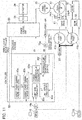
- Fig. 10 is a block diagram showing the system configuration and control blocks of the hybrid construction machine in accordance with the second embodiment of the present invention.
- Reference characters in Fig. 10 identical with those in Figs. 1 - 9 represent components identical or corresponding to those in Figs. 1 - 9 , and thus repeated explanation thereof is omitted for brevity.
- This embodiment differs from the first embodiment in that a hydraulic pump 41a for supplying the hydraulic oil to the swing hydraulic motor 27 and a hydraulic pump 41b for supplying the hydraulic oil to the boom cylinder 32 are provided separately.
- the hydraulic pump 41a is controlled by the controller 80 via the regulator 64.
- the functional block inside of the controller 80 differing from that in the first embodiment is the limit gain calculation block 83c.
- the limit gain calculation block 83c in this embodiment receives the angular speed signal ⁇ of the swing electric motor 25 from the power control unit 55 and the swing operation command "is” converted into an electric signal by the hydraulic-electric conversion unit 74a as input signals, calculates gain outputs K1 and K2 from these values, calculates a limit gain K by multiplying the gain outputs and K2 together, and outputs the calculated limit gain K.
- the limit gain calculation block 83c in this embodiment determines the limit gain K from the angular speed signal ⁇ of the swing electric motor 25 and the swing operation command "is” only, without referring to the boom raising operation command "ib".
- the bottom pressure of the boom cylinder 32 does not decrease even though the torque To of the swing hydraulic motor 27 is reduced by the added torque of the swing electric motor 25.
- the total torque Tt of the swing hydraulic motor 27 and the swing electric motor 25 does not change, nor does the bottom pressure Pb of the boom cylinder 32. Consequently, the hybrid construction machine of this embodiment is easy to operate for the operator since the relationship between the swing motor angular speed ⁇ and the boom raising level Db does not change even when the voltage value Vc of the capacitor 24 gets higher or lower than the operational threshold Vp.
- the hydraulic pump 41a for supplying the hydraulic oil to the swing hydraulic motor 27 and the hydraulic pump 41b for supplying the hydraulic oil to the boom cylinder 32 are provided separately. Even when both the swing operation of the swing structure 20 and the boom raising operation of the boom 31 are under way, the control for generating the torque of the swing electric motor 25 and reducing the power of the hydraulic pump 41a by an amount corresponding to the added torque of the swing electric motor 25 is carried out if the voltage value Vc of the capacitor 24 is higher than the operational threshold Vp. Therefore, satisfactory operability in the combined operation of the swing operation of the swing structure 20 and the boom raising operation of the boom 31 can be secured irrespective of the operating status of the swing electric motor 25.
- Fig. 11 is a block diagram showing the system configuration and control blocks of the hybrid construction machine in accordance with the third embodiment of the present invention.
- Reference characters in Fig. 11 identical with those in Figs. 1 - 10 represent components identical or corresponding to those in Figs. 1 - 10 , and thus repeated explanation thereof is omitted for brevity.
- the hydraulic pump 41a for supplying the hydraulic oil to the swing hydraulic motor 27 and the hydraulic pump 41b for supplying the hydraulic oil to the boom cylinder 32 are provided separately in the same way as the second embodiment.
- This embodiment differs from the second embodiment in that the hydraulic pump 41b is controlled by the controller 80 via the regulator 64.
- the functional block inside of the controller 80 differing from that in the first embodiment is the hydraulic pump power reduction control block 83f.
- the hydraulic pump power reduction control block 83f receives the torque command value EA calculated by the torque command value calculation block 83e as an input signal and outputs the power reduction command EB (for reducing the discharge flow rate of the hydraulic pump 41) so that the torque of the swing hydraulic motor 27 is reduced by the added torque of the swing electric motor 25.
- This embodiment differs from the first embodiment in that the hydraulic pump power reduction control block 83f receives the torque command value EA calculated by the torque command value calculation block 83e as an input signal and outputs a power enhancement command EB for increasing the discharge flow rate of the hydraulic pump 41b (supplying the hydraulic oil to the boom cylinder 32) by the added torque of the swing electric motor 25.
- the control in this embodiment is executed so as to enhance the power of the hydraulic pump 41b when the torque of the swing electric motor 25 is increased, and to reduce the power of the hydraulic pump 41b when the torque of the swing electric motor 25 is reduced.
- the limit gain calculation block 83c of the controller 80 determines the limit gain K from the angular speed signal ⁇ of the swing electric motor 25 and the swing operation command "is” only, without referring to the boom raising operation command "ib".
- the hydraulic pump 41a for supplying the hydraulic oil to the swing hydraulic motor 27 and the hydraulic pump 41b for supplying the hydraulic oil to the boom cylinder 32 are provided separately. Even when the swing boom raising operation is under way, the control for generating the torque of the swing electric motor 25 and enhancing the power of the hydraulic pump 41b by an amount corresponding to the added torque of the swing electric motor 25 is carried out if the voltage value Vc of the capacitor 24 is higher than the operational threshold Vp. Therefore, satisfactory operability in the combined operation of the swing operation of the swing structure 20 and the boom raising operation of the boom 31 can be secured irrespective of the operating status of the swing electric motor 25.
Applications Claiming Priority (2)
| Application Number | Priority Date | Filing Date | Title |
|---|---|---|---|
| JP2011022083A JP5356427B2 (ja) | 2011-02-03 | 2011-02-03 | ハイブリッド式建設機械 |
| PCT/JP2012/050128 WO2012105279A1 (ja) | 2011-02-03 | 2012-01-05 | ハイブリッド式建設機械 |
Publications (3)
| Publication Number | Publication Date |
|---|---|
| EP2672025A1 EP2672025A1 (en) | 2013-12-11 |
| EP2672025A4 EP2672025A4 (en) | 2018-04-04 |
| EP2672025B1 true EP2672025B1 (en) | 2019-10-23 |
Family
ID=46602500
Family Applications (1)
| Application Number | Title | Priority Date | Filing Date |
|---|---|---|---|
| EP12742161.8A Active EP2672025B1 (en) | 2011-02-03 | 2012-01-05 | Hybrid construction machine |
Country Status (6)
| Country | Link |
|---|---|
| US (1) | US8958958B2 (ko) |
| EP (1) | EP2672025B1 (ko) |
| JP (1) | JP5356427B2 (ko) |
| KR (1) | KR101834598B1 (ko) |
| CN (1) | CN103348065B (ko) |
| WO (1) | WO2012105279A1 (ko) |
Families Citing this family (18)
| Publication number | Priority date | Publication date | Assignee | Title |
|---|---|---|---|---|
| JP5356427B2 (ja) * | 2011-02-03 | 2013-12-04 | 日立建機株式会社 | ハイブリッド式建設機械 |
| JP5928065B2 (ja) * | 2012-03-27 | 2016-06-01 | コベルコ建機株式会社 | 制御装置及びこれを備えた建設機械 |
| KR101955751B1 (ko) * | 2012-11-08 | 2019-03-07 | 히다찌 겐끼 가부시키가이샤 | 건설 기계 |
| KR20140101279A (ko) * | 2013-02-08 | 2014-08-19 | 스미토모 겐키 가부시키가이샤 | 쇼벨 및 쇼벨의 제어방법 |
| JP5873456B2 (ja) * | 2013-04-05 | 2016-03-01 | 川崎重工業株式会社 | 作業機械の駆動制御システム、それを備える作業機械、及びその駆動制御方法 |
| JP5969437B2 (ja) * | 2013-08-22 | 2016-08-17 | 日立建機株式会社 | 建設機械 |
| JP6214327B2 (ja) * | 2013-10-18 | 2017-10-18 | 日立建機株式会社 | ハイブリッド式建設機械 |
| JP6091444B2 (ja) * | 2014-02-03 | 2017-03-08 | 日立建機株式会社 | ハイブリッド建設機械 |
| JP6150740B2 (ja) * | 2014-02-20 | 2017-06-21 | 日立建機株式会社 | 建設機械 |
| KR101756572B1 (ko) * | 2014-06-04 | 2017-07-10 | 가부시키가이샤 고마쓰 세이사쿠쇼 | 건설 기계의 제어 시스템, 건설 기계, 및 건설 기계의 제어 방법 |
| JP6190763B2 (ja) * | 2014-06-05 | 2017-08-30 | 日立建機株式会社 | ハイブリッド式建設機械 |
| CA2897097C (en) | 2014-07-15 | 2022-07-26 | Harnischfeger Technologies, Inc. | Adaptive load compensation for an industrial machine |
| US9283949B2 (en) * | 2014-07-22 | 2016-03-15 | Google Inc. | Hybrid hydraulic and electrically actuated mobile robot |
| JP6692568B2 (ja) * | 2015-01-06 | 2020-05-13 | 住友重機械工業株式会社 | 建設機械 |
| CN107306500B (zh) * | 2016-02-29 | 2020-07-10 | 株式会社小松制作所 | 作业机械的控制装置、作业机械以及作业机械的控制方法 |
| JP6400220B2 (ja) * | 2016-03-11 | 2018-10-03 | 日立建機株式会社 | 建設機械の制御装置 |
| JP6630257B2 (ja) * | 2016-09-30 | 2020-01-15 | 日立建機株式会社 | 建設機械 |
| WO2017126182A1 (ja) * | 2016-10-28 | 2017-07-27 | 株式会社小松製作所 | 積込機械の制御システム及び積込機械の制御方法 |
Family Cites Families (23)
| Publication number | Priority date | Publication date | Assignee | Title |
|---|---|---|---|---|
| WO1989011041A1 (en) * | 1988-05-10 | 1989-11-16 | Hitachi Construction Machinery Co., Ltd. | Hydraulic drive unit for construction machinery |
| JP3647319B2 (ja) | 1999-06-28 | 2005-05-11 | 株式会社神戸製鋼所 | 油圧駆動装置 |
| JP4024120B2 (ja) | 2002-09-30 | 2007-12-19 | 日立建機株式会社 | 油圧建設機械のエネルギ回生装置 |
| JP2004360216A (ja) * | 2003-06-02 | 2004-12-24 | Sumitomo (Shi) Construction Machinery Manufacturing Co Ltd | 建設機械の旋回駆動装置 |
| JP4517703B2 (ja) * | 2004-04-01 | 2010-08-04 | コベルコ建機株式会社 | 旋回式作業機械 |
| JP4171467B2 (ja) * | 2005-01-20 | 2008-10-22 | 株式会社小松製作所 | 建設機械の制御モード切換装置および建設機械 |
| DE112006002887B4 (de) * | 2005-10-31 | 2017-11-16 | Komatsu Ltd. | Steuergerät für eine Arbeitsmaschine |
| JP4851802B2 (ja) * | 2006-02-01 | 2012-01-11 | 日立建機株式会社 | 建設機械の旋回駆動装置 |
| JP4732284B2 (ja) * | 2006-09-09 | 2011-07-27 | 東芝機械株式会社 | 慣性体の有する運動エネルギを電気エネルギに変換するハイブリッド型建設機械 |
| JP4892057B2 (ja) * | 2007-03-28 | 2012-03-07 | 株式会社小松製作所 | ハイブリッド建設機械の制御方法およびハイブリッド建設機械 |
| JP5351471B2 (ja) * | 2008-09-12 | 2013-11-27 | 住友建機株式会社 | 作業機械の駆動装置 |
| JP4609567B2 (ja) * | 2008-10-29 | 2011-01-12 | コベルコ建機株式会社 | ハイブリッド作業機械 |
| KR101112135B1 (ko) * | 2009-07-28 | 2012-02-22 | 볼보 컨스트럭션 이큅먼트 에이비 | 전기모터를 이용한 건설기계의 선회 제어시스템 및 방법 |
| KR101112136B1 (ko) * | 2009-07-29 | 2012-02-22 | 볼보 컨스트럭션 이큅먼트 에이비 | 하이브리드식 건설기계의 제어시스템 및 방법 |
| JP5171888B2 (ja) * | 2010-06-09 | 2013-03-27 | 日立建機株式会社 | 建設機械 |
| CN103052754B (zh) * | 2010-10-22 | 2015-11-25 | 日立建机株式会社 | 电动式工程机械 |
| CN103249894B (zh) * | 2010-12-07 | 2016-03-16 | 沃尔沃建造设备有限公司 | 用于混合动力施工机械的回转控制系统 |
| JP5356427B2 (ja) * | 2011-02-03 | 2013-12-04 | 日立建機株式会社 | ハイブリッド式建設機械 |
| JP5562272B2 (ja) * | 2011-03-01 | 2014-07-30 | 日立建機株式会社 | ハイブリッド式建設機械 |
| JP5509433B2 (ja) * | 2011-03-22 | 2014-06-04 | 日立建機株式会社 | ハイブリッド式建設機械及びこれに用いる補助制御装置 |
| JP5476555B2 (ja) * | 2011-03-25 | 2014-04-23 | 日立建機株式会社 | ハイブリッド式建設機械 |
| JP5647052B2 (ja) * | 2011-03-25 | 2014-12-24 | 日立建機株式会社 | ハイブリッド式建設機械 |
| US20120283919A1 (en) * | 2011-05-04 | 2012-11-08 | Caterpillar Inc. | Electric swing drive control system and method |
-
2011
- 2011-02-03 JP JP2011022083A patent/JP5356427B2/ja active Active
-
2012
- 2012-01-05 EP EP12742161.8A patent/EP2672025B1/en active Active
- 2012-01-05 KR KR1020137018916A patent/KR101834598B1/ko active IP Right Grant
- 2012-01-05 US US13/982,563 patent/US8958958B2/en active Active
- 2012-01-05 CN CN201280007457.4A patent/CN103348065B/zh active Active
- 2012-01-05 WO PCT/JP2012/050128 patent/WO2012105279A1/ja active Application Filing
Non-Patent Citations (1)
| Title |
|---|
| None * |
Also Published As
| Publication number | Publication date |
|---|---|
| WO2012105279A1 (ja) | 2012-08-09 |
| EP2672025A1 (en) | 2013-12-11 |
| JP2012162861A (ja) | 2012-08-30 |
| JP5356427B2 (ja) | 2013-12-04 |
| CN103348065B (zh) | 2015-10-14 |
| KR101834598B1 (ko) | 2018-04-13 |
| EP2672025A4 (en) | 2018-04-04 |
| KR20140009290A (ko) | 2014-01-22 |
| US8958958B2 (en) | 2015-02-17 |
| US20140199148A1 (en) | 2014-07-17 |
| CN103348065A (zh) | 2013-10-09 |
Similar Documents
| Publication | Publication Date | Title |
|---|---|---|
| EP2672025B1 (en) | Hybrid construction machine | |
| EP2573281B1 (en) | Hybrid construction machinery | |
| KR101834589B1 (ko) | 선회체를 갖는 건설 기계 | |
| CN102301583B (zh) | 混合式工作机械及伺服控制系统 | |
| KR101818284B1 (ko) | 선회체를 갖는 건설 기계 | |
| US9777463B2 (en) | Construction machine | |
| JP2008291522A (ja) | ハイブリッド型駆動装置を備えた建設機械 | |
| US10272900B2 (en) | Hybrid wheel loader | |
| WO2015030143A1 (ja) | 作業機械 | |
| JP6771487B2 (ja) | 作業機械 | |
| EP3085969B1 (en) | Construction machine | |
| KR20130114871A (ko) | 굴삭기 전기 동력시스템 | |
| WO2020039862A1 (ja) | ハイブリッド建設機械 | |
| JP2016127728A (ja) | 作業機械の駆動制御システム、それを備える作業機械、及びその駆動制御方法 | |
| JP5723947B2 (ja) | 旋回体を有する建設機械 | |
| JP2020141477A (ja) | 作業機械 | |
| JP5198048B2 (ja) | 建設機械 | |
| JP2014231297A (ja) | ハイブリッド作業機械 |
Legal Events
| Date | Code | Title | Description |
|---|---|---|---|
| PUAI | Public reference made under article 153(3) epc to a published international application that has entered the european phase |
Free format text: ORIGINAL CODE: 0009012 |
|
| 17P | Request for examination filed |
Effective date: 20130903 |
|
| AK | Designated contracting states |
Kind code of ref document: A1 Designated state(s): AL AT BE BG CH CY CZ DE DK EE ES FI FR GB GR HR HU IE IS IT LI LT LU LV MC MK MT NL NO PL PT RO RS SE SI SK SM TR |
|
| DAX | Request for extension of the european patent (deleted) | ||
| RA4 | Supplementary search report drawn up and despatched (corrected) |
Effective date: 20180306 |
|
| RIC1 | Information provided on ipc code assigned before grant |
Ipc: E02F 9/12 20060101ALI20180228BHEP Ipc: E02F 9/22 20060101ALI20180228BHEP Ipc: E02F 9/20 20060101AFI20180228BHEP |
|
| RIC1 | Information provided on ipc code assigned before grant |
Ipc: E02F 9/20 20060101AFI20190222BHEP Ipc: E02F 9/12 20060101ALI20190222BHEP Ipc: E02F 9/22 20060101ALI20190222BHEP |
|
| GRAP | Despatch of communication of intention to grant a patent |
Free format text: ORIGINAL CODE: EPIDOSNIGR1 |
|
| STAA | Information on the status of an ep patent application or granted ep patent |
Free format text: STATUS: GRANT OF PATENT IS INTENDED |
|
| INTG | Intention to grant announced |
Effective date: 20190627 |
|
| RIN1 | Information on inventor provided before grant (corrected) |
Inventor name: IMURA SHINYA Inventor name: NISHIKAWA SHINJI Inventor name: ISHIKAWA KOUJI Inventor name: EDAMURA MANABU Inventor name: SATAKE HIDETOSHI Inventor name: OOKI TAKATOSHI |
|
| GRAS | Grant fee paid |
Free format text: ORIGINAL CODE: EPIDOSNIGR3 |
|
| GRAA | (expected) grant |
Free format text: ORIGINAL CODE: 0009210 |
|
| STAA | Information on the status of an ep patent application or granted ep patent |
Free format text: STATUS: THE PATENT HAS BEEN GRANTED |
|
| RIN1 | Information on inventor provided before grant (corrected) |
Inventor name: NISHIKAWA SHINJI Inventor name: OOKI TAKATOSHI Inventor name: SATAKE HIDETOSHI Inventor name: ISHIKAWA KOUJI Inventor name: IMURA SHINYA Inventor name: EDAMURA MANABU |
|
| AK | Designated contracting states |
Kind code of ref document: B1 Designated state(s): AL AT BE BG CH CY CZ DE DK EE ES FI FR GB GR HR HU IE IS IT LI LT LU LV MC MK MT NL NO PL PT RO RS SE SI SK SM TR |
|
| RAP1 | Party data changed (applicant data changed or rights of an application transferred) |
Owner name: HITACHI CONSTRUCTION MACHINERY CO., LTD. |
|
| REG | Reference to a national code |
Ref country code: GB Ref legal event code: FG4D |
|
| REG | Reference to a national code |
Ref country code: CH Ref legal event code: EP |
|
| REG | Reference to a national code |
Ref country code: IE Ref legal event code: FG4D |
|
| REG | Reference to a national code |
Ref country code: DE Ref legal event code: R096 Ref document number: 602012065083 Country of ref document: DE |
|
| REG | Reference to a national code |
Ref country code: AT Ref legal event code: REF Ref document number: 1193756 Country of ref document: AT Kind code of ref document: T Effective date: 20191115 |
|
| REG | Reference to a national code |
Ref country code: NL Ref legal event code: MP Effective date: 20191023 |
|
| REG | Reference to a national code |
Ref country code: LT Ref legal event code: MG4D |
|
| PG25 | Lapsed in a contracting state [announced via postgrant information from national office to epo] |
Ref country code: ES Free format text: LAPSE BECAUSE OF FAILURE TO SUBMIT A TRANSLATION OF THE DESCRIPTION OR TO PAY THE FEE WITHIN THE PRESCRIBED TIME-LIMIT Effective date: 20191023 Ref country code: LV Free format text: LAPSE BECAUSE OF FAILURE TO SUBMIT A TRANSLATION OF THE DESCRIPTION OR TO PAY THE FEE WITHIN THE PRESCRIBED TIME-LIMIT Effective date: 20191023 Ref country code: SE Free format text: LAPSE BECAUSE OF FAILURE TO SUBMIT A TRANSLATION OF THE DESCRIPTION OR TO PAY THE FEE WITHIN THE PRESCRIBED TIME-LIMIT Effective date: 20191023 Ref country code: NL Free format text: LAPSE BECAUSE OF FAILURE TO SUBMIT A TRANSLATION OF THE DESCRIPTION OR TO PAY THE FEE WITHIN THE PRESCRIBED TIME-LIMIT Effective date: 20191023 Ref country code: GR Free format text: LAPSE BECAUSE OF FAILURE TO SUBMIT A TRANSLATION OF THE DESCRIPTION OR TO PAY THE FEE WITHIN THE PRESCRIBED TIME-LIMIT Effective date: 20200124 Ref country code: PL Free format text: LAPSE BECAUSE OF FAILURE TO SUBMIT A TRANSLATION OF THE DESCRIPTION OR TO PAY THE FEE WITHIN THE PRESCRIBED TIME-LIMIT Effective date: 20191023 Ref country code: BG Free format text: LAPSE BECAUSE OF FAILURE TO SUBMIT A TRANSLATION OF THE DESCRIPTION OR TO PAY THE FEE WITHIN THE PRESCRIBED TIME-LIMIT Effective date: 20200123 Ref country code: NO Free format text: LAPSE BECAUSE OF FAILURE TO SUBMIT A TRANSLATION OF THE DESCRIPTION OR TO PAY THE FEE WITHIN THE PRESCRIBED TIME-LIMIT Effective date: 20200123 Ref country code: FI Free format text: LAPSE BECAUSE OF FAILURE TO SUBMIT A TRANSLATION OF THE DESCRIPTION OR TO PAY THE FEE WITHIN THE PRESCRIBED TIME-LIMIT Effective date: 20191023 Ref country code: LT Free format text: LAPSE BECAUSE OF FAILURE TO SUBMIT A TRANSLATION OF THE DESCRIPTION OR TO PAY THE FEE WITHIN THE PRESCRIBED TIME-LIMIT Effective date: 20191023 Ref country code: PT Free format text: LAPSE BECAUSE OF FAILURE TO SUBMIT A TRANSLATION OF THE DESCRIPTION OR TO PAY THE FEE WITHIN THE PRESCRIBED TIME-LIMIT Effective date: 20200224 |
|
| PG25 | Lapsed in a contracting state [announced via postgrant information from national office to epo] |
Ref country code: IS Free format text: LAPSE BECAUSE OF FAILURE TO SUBMIT A TRANSLATION OF THE DESCRIPTION OR TO PAY THE FEE WITHIN THE PRESCRIBED TIME-LIMIT Effective date: 20200224 Ref country code: RS Free format text: LAPSE BECAUSE OF FAILURE TO SUBMIT A TRANSLATION OF THE DESCRIPTION OR TO PAY THE FEE WITHIN THE PRESCRIBED TIME-LIMIT Effective date: 20191023 Ref country code: HR Free format text: LAPSE BECAUSE OF FAILURE TO SUBMIT A TRANSLATION OF THE DESCRIPTION OR TO PAY THE FEE WITHIN THE PRESCRIBED TIME-LIMIT Effective date: 20191023 |
|
| PG25 | Lapsed in a contracting state [announced via postgrant information from national office to epo] |
Ref country code: AL Free format text: LAPSE BECAUSE OF FAILURE TO SUBMIT A TRANSLATION OF THE DESCRIPTION OR TO PAY THE FEE WITHIN THE PRESCRIBED TIME-LIMIT Effective date: 20191023 |
|
| REG | Reference to a national code |
Ref country code: DE Ref legal event code: R097 Ref document number: 602012065083 Country of ref document: DE |
|
| PG2D | Information on lapse in contracting state deleted |
Ref country code: IS |
|
| PG25 | Lapsed in a contracting state [announced via postgrant information from national office to epo] |
Ref country code: RO Free format text: LAPSE BECAUSE OF FAILURE TO SUBMIT A TRANSLATION OF THE DESCRIPTION OR TO PAY THE FEE WITHIN THE PRESCRIBED TIME-LIMIT Effective date: 20191023 Ref country code: EE Free format text: LAPSE BECAUSE OF FAILURE TO SUBMIT A TRANSLATION OF THE DESCRIPTION OR TO PAY THE FEE WITHIN THE PRESCRIBED TIME-LIMIT Effective date: 20191023 Ref country code: DK Free format text: LAPSE BECAUSE OF FAILURE TO SUBMIT A TRANSLATION OF THE DESCRIPTION OR TO PAY THE FEE WITHIN THE PRESCRIBED TIME-LIMIT Effective date: 20191023 Ref country code: CZ Free format text: LAPSE BECAUSE OF FAILURE TO SUBMIT A TRANSLATION OF THE DESCRIPTION OR TO PAY THE FEE WITHIN THE PRESCRIBED TIME-LIMIT Effective date: 20191023 Ref country code: IS Free format text: LAPSE BECAUSE OF FAILURE TO SUBMIT A TRANSLATION OF THE DESCRIPTION OR TO PAY THE FEE WITHIN THE PRESCRIBED TIME-LIMIT Effective date: 20200223 |
|
| REG | Reference to a national code |
Ref country code: AT Ref legal event code: MK05 Ref document number: 1193756 Country of ref document: AT Kind code of ref document: T Effective date: 20191023 |
|
| PLBE | No opposition filed within time limit |
Free format text: ORIGINAL CODE: 0009261 |
|
| STAA | Information on the status of an ep patent application or granted ep patent |
Free format text: STATUS: NO OPPOSITION FILED WITHIN TIME LIMIT |
|
| PG25 | Lapsed in a contracting state [announced via postgrant information from national office to epo] |
Ref country code: SM Free format text: LAPSE BECAUSE OF FAILURE TO SUBMIT A TRANSLATION OF THE DESCRIPTION OR TO PAY THE FEE WITHIN THE PRESCRIBED TIME-LIMIT Effective date: 20191023 Ref country code: SK Free format text: LAPSE BECAUSE OF FAILURE TO SUBMIT A TRANSLATION OF THE DESCRIPTION OR TO PAY THE FEE WITHIN THE PRESCRIBED TIME-LIMIT Effective date: 20191023 Ref country code: IT Free format text: LAPSE BECAUSE OF FAILURE TO SUBMIT A TRANSLATION OF THE DESCRIPTION OR TO PAY THE FEE WITHIN THE PRESCRIBED TIME-LIMIT Effective date: 20191023 Ref country code: MC Free format text: LAPSE BECAUSE OF FAILURE TO SUBMIT A TRANSLATION OF THE DESCRIPTION OR TO PAY THE FEE WITHIN THE PRESCRIBED TIME-LIMIT Effective date: 20191023 |
|
| REG | Reference to a national code |
Ref country code: CH Ref legal event code: PL |
|
| 26N | No opposition filed |
Effective date: 20200724 |
|
| REG | Reference to a national code |
Ref country code: BE Ref legal event code: MM Effective date: 20200131 |
|
| PG25 | Lapsed in a contracting state [announced via postgrant information from national office to epo] |
Ref country code: FR Free format text: LAPSE BECAUSE OF NON-PAYMENT OF DUE FEES Effective date: 20200131 Ref country code: LU Free format text: LAPSE BECAUSE OF NON-PAYMENT OF DUE FEES Effective date: 20200105 |
|
| PG25 | Lapsed in a contracting state [announced via postgrant information from national office to epo] |
Ref country code: SI Free format text: LAPSE BECAUSE OF FAILURE TO SUBMIT A TRANSLATION OF THE DESCRIPTION OR TO PAY THE FEE WITHIN THE PRESCRIBED TIME-LIMIT Effective date: 20191023 Ref country code: LI Free format text: LAPSE BECAUSE OF NON-PAYMENT OF DUE FEES Effective date: 20200131 Ref country code: CH Free format text: LAPSE BECAUSE OF NON-PAYMENT OF DUE FEES Effective date: 20200131 Ref country code: AT Free format text: LAPSE BECAUSE OF FAILURE TO SUBMIT A TRANSLATION OF THE DESCRIPTION OR TO PAY THE FEE WITHIN THE PRESCRIBED TIME-LIMIT Effective date: 20191023 Ref country code: BE Free format text: LAPSE BECAUSE OF NON-PAYMENT OF DUE FEES Effective date: 20200131 |
|
| PG25 | Lapsed in a contracting state [announced via postgrant information from national office to epo] |
Ref country code: IE Free format text: LAPSE BECAUSE OF NON-PAYMENT OF DUE FEES Effective date: 20200105 |
|
| PG25 | Lapsed in a contracting state [announced via postgrant information from national office to epo] |
Ref country code: TR Free format text: LAPSE BECAUSE OF FAILURE TO SUBMIT A TRANSLATION OF THE DESCRIPTION OR TO PAY THE FEE WITHIN THE PRESCRIBED TIME-LIMIT Effective date: 20191023 Ref country code: MT Free format text: LAPSE BECAUSE OF FAILURE TO SUBMIT A TRANSLATION OF THE DESCRIPTION OR TO PAY THE FEE WITHIN THE PRESCRIBED TIME-LIMIT Effective date: 20191023 Ref country code: CY Free format text: LAPSE BECAUSE OF FAILURE TO SUBMIT A TRANSLATION OF THE DESCRIPTION OR TO PAY THE FEE WITHIN THE PRESCRIBED TIME-LIMIT Effective date: 20191023 |
|
| PG25 | Lapsed in a contracting state [announced via postgrant information from national office to epo] |
Ref country code: MK Free format text: LAPSE BECAUSE OF FAILURE TO SUBMIT A TRANSLATION OF THE DESCRIPTION OR TO PAY THE FEE WITHIN THE PRESCRIBED TIME-LIMIT Effective date: 20191023 |
|
| PGFP | Annual fee paid to national office [announced via postgrant information from national office to epo] |
Ref country code: DE Payment date: 20221130 Year of fee payment: 12 |
|
| PGFP | Annual fee paid to national office [announced via postgrant information from national office to epo] |
Ref country code: GB Payment date: 20231130 Year of fee payment: 13 |