EP2668487B1 - Devices, systems, and methods for extracting a material from a material sample - Google Patents
Devices, systems, and methods for extracting a material from a material sample Download PDFInfo
- Publication number
- EP2668487B1 EP2668487B1 EP11857029.0A EP11857029A EP2668487B1 EP 2668487 B1 EP2668487 B1 EP 2668487B1 EP 11857029 A EP11857029 A EP 11857029A EP 2668487 B1 EP2668487 B1 EP 2668487B1
- Authority
- EP
- European Patent Office
- Prior art keywords
- liquid
- cutting tip
- support substrate
- biological material
- biological sample
- Prior art date
- Legal status (The legal status is an assumption and is not a legal conclusion. Google has not performed a legal analysis and makes no representation as to the accuracy of the status listed.)
- Active
Links
Images


Classifications
-
- G—PHYSICS
- G01—MEASURING; TESTING
- G01N—INVESTIGATING OR ANALYSING MATERIALS BY DETERMINING THEIR CHEMICAL OR PHYSICAL PROPERTIES
- G01N33/00—Investigating or analysing materials by specific methods not covered by groups G01N1/00 - G01N31/00
- G01N33/48—Biological material, e.g. blood, urine; Haemocytometers
-
- G—PHYSICS
- G01—MEASURING; TESTING
- G01N—INVESTIGATING OR ANALYSING MATERIALS BY DETERMINING THEIR CHEMICAL OR PHYSICAL PROPERTIES
- G01N1/00—Sampling; Preparing specimens for investigation
- G01N1/28—Preparing specimens for investigation including physical details of (bio-)chemical methods covered elsewhere, e.g. G01N33/50, C12Q
- G01N1/30—Staining; Impregnating ; Fixation; Dehydration; Multistep processes for preparing samples of tissue, cell or nucleic acid material and the like for analysis
- G01N1/31—Apparatus therefor
-
- G—PHYSICS
- G01—MEASURING; TESTING
- G01N—INVESTIGATING OR ANALYSING MATERIALS BY DETERMINING THEIR CHEMICAL OR PHYSICAL PROPERTIES
- G01N1/00—Sampling; Preparing specimens for investigation
- G01N1/02—Devices for withdrawing samples
- G01N1/04—Devices for withdrawing samples in the solid state, e.g. by cutting
-
- G—PHYSICS
- G01—MEASURING; TESTING
- G01N—INVESTIGATING OR ANALYSING MATERIALS BY DETERMINING THEIR CHEMICAL OR PHYSICAL PROPERTIES
- G01N1/00—Sampling; Preparing specimens for investigation
- G01N1/02—Devices for withdrawing samples
- G01N1/10—Devices for withdrawing samples in the liquid or fluent state
-
- G—PHYSICS
- G01—MEASURING; TESTING
- G01N—INVESTIGATING OR ANALYSING MATERIALS BY DETERMINING THEIR CHEMICAL OR PHYSICAL PROPERTIES
- G01N1/00—Sampling; Preparing specimens for investigation
- G01N1/28—Preparing specimens for investigation including physical details of (bio-)chemical methods covered elsewhere, e.g. G01N33/50, C12Q
- G01N1/286—Preparing specimens for investigation including physical details of (bio-)chemical methods covered elsewhere, e.g. G01N33/50, C12Q involving mechanical work, e.g. chopping, disintegrating, compacting, homogenising
- G01N2001/2873—Cutting or cleaving
-
- G—PHYSICS
- G01—MEASURING; TESTING
- G01N—INVESTIGATING OR ANALYSING MATERIALS BY DETERMINING THEIR CHEMICAL OR PHYSICAL PROPERTIES
- G01N1/00—Sampling; Preparing specimens for investigation
- G01N1/28—Preparing specimens for investigation including physical details of (bio-)chemical methods covered elsewhere, e.g. G01N33/50, C12Q
- G01N1/38—Diluting, dispersing or mixing samples
- G01N2001/383—Diluting, dispersing or mixing samples collecting and diluting in a flow of liquid
Definitions
- WO 2009/008843 A1 and WO 00/57153 A1 relate to a method for selectively extracting biological material from a biological sample and an extraction device for use in extracting biological material from a biological sample.
- these documents describe a method for selectively extracting biological material from a biological sample, comprising: I
- the present disclosure provides devices, systems, and associated methods for selectively extracting a material from a sample. More specifically, the present invention provides a method for selectively extracting biological material from a biological sample in accordance with claim 1. Further, the present invention provides for the use of an extraction device in a system for selectively extracting biological material from a biological sample in accordance with claim 2. Additionally, the present invention provides a system for selectively extracting biological material from a biological sample in accordance with claim 3.
- the scope of the present invention is defined by the claims. Any subject matter disclosed hereinafter that falls outside of the scope of the claims is provided for information purposes only.
- Described hereinafter is a method for selectively extracting a biological material from a biological sample, which includes identifying a region of material to be extracted from a sample, applying an extraction tool to the region of material to disrupt material from the sample, and dispensing a liquid at the region of material.
- the method includes aspirating the liquid and the disrupted material from the sample.
- the extraction tool imparts a cutting motion to the region of material; the cutting motion is rotating.
- the liquid is dispensed at an interface between the region of material and the extraction tool.
- disrupted material is readily mixed with the liquid as it is disrupted.
- the liquid is dispensed and aspirated simultaneously.
- the disrupted material can be quickly removed by the aspirated liquid from the sample.
- the liquid is dispensed and aspirated by the extraction tool, or in other words, the liquid is dispensed and aspirated from ports coupled to, or otherwise associated with, or formed integrally with, the extraction tool.
- identifying a region of material further includes obtaining a real time digital image of the sample and defining an area of interest on the digital image corresponding to the region of material, where movement of the sample is reflected by movement of the area of interest and/or the digital image to maintain position of the area of interest relative to the material.
- the sample is a series of sections, and the area of interest is defined on one section that corresponds to the region of material from a different section.
- An extraction device for selectively extracting a biological material from a biological sample includes a housing and at least one cutting tip rotatably coupled to the housing and configured to be rotatably driven by a motor.
- the cutting tip is operable to disrupt material from a region of a sample.
- the device further includes at least one liquid dispensing port coupled to the housing and located proximal to the cutting tip, where the liquid dispensing port is operable to dispense liquid at the cutting tip.
- At least one liquid aspiration port is coupled to the housing and located proximal to the cutting tip, where the liquid aspiration port is operable to aspirate liquid and disrupted biological material from a region proximal to the cutting tip.
- the at least one liquid dispensing port and the at least one liquid aspiration port rotate with the cutting tip. The at least one liquid dispensing port and the at least one liquid aspiration port are operable to function simultaneously.
- the cutting tip can be of any size, depending on the desired cutting task.
- the cutting tip is sized to disrupt an area of biological material of from about 10 ⁇ m in size to about 1 mm in size.
- the cutting tip is sized to disrupt an area of material of from about 100 ⁇ m in size to about 250 ⁇ m in size.
- a system for selectively extracting biological material from a biological sample that includes an extraction device as has been described herein positioned to operationally face a support substrate and to engage a sample disposed on the support substrate.
- a motor is operationally coupled to the extraction device and operable to rotate the cutting tip.
- a fluidics system is coupled to the extraction device and operable to deliver fluid to the liquid dispensing port and withdraw fluid from the liquid removal port.
- a positional movement system is coupled to the extraction device and operable to move either the cutting tip of the extraction device relative to the support substrate or the support substrate relative to the cutting tip.
- a visualization system is included and is positioned to provide a visual display of a sample, such as a biological sample, placed on the support substrate.
- the visualization system can include a variety of visualization devices, including without limitation, digital imagers, optical imagers, microscopes, inverted microscopes, and the like, including combinations thereof.
- the support substrate is transparent.
- the visualization system is an inverted microscope positioned to provide the visual display from a side of the transparent support substrate opposite the cutting tip.
- the visualization system is operable to provide a real time visual display of the cutting tip during an extraction procedure.
- the system for selectively extracting biological material from a biological sample can further include a manual manipulation system.
- This manual system is functionally coupled to the positional movement system and is operable to allow a user to move the cutting tip and/or the support substrate relative to one another.
- the system for selectively extracting biological material from a biological sample can further include an automatic manipulation system.
- an automatic system is functionally coupled to the positional movement system and is operable to automatically move the cutting tip and/or the support substrate relative to one another.
- the automatic system further includes a processing system functionally coupled to the automatic manipulation system. The processing system is operable to identify and locate a predetermined region of material to be extracted from a sample and move the cutting tip and/or support substrate relative to one another to extract the biological material via the automatic manipulation system.
- the term “substantially” refers to the complete or nearly complete extent or degree of an action, characteristic, property, state, structure, item, or result.
- the exact allowable degree of deviation from absolute completeness may in some cases depend on the specific context. However, generally speaking the nearness of completion will be so as to have the same overall result as if absolute and total completion were obtained.
- the use of “substantially” is equally applicable when used in a negative connotation to refer to the complete or near complete lack of an action, characteristic, property, state, structure, item, or result.
- a composition that is "substantially free of” particles would either completely lack particles, or so nearly completely lack particles that the effect would be the same as if it completely lacked particles.
- a composition that is "substantially free of" an ingredient or element may still actually contain such item as long as there is no measurable effect on the property of interest thereof.
- the term “about” is used to provide flexibility to a numerical range endpoint by providing that a given value may be “a little above” or “a little below” the endpoint with a degree of flexibility as would be generally recognized by those skilled in the art. Further, the term about explicitly includes the exact endpoint, unless specifically stated otherwise.
- the present disclosure relates to devices, systems, and methods for removing material from a material sample.
- the material that has been extracted is saved for further processing or analysis. Such may be the case for procedures involved in forensics, testing of material purity, histopathology, core sampling, and the like.
- serial sections of a material sample can be generated that allows a destructive sampling of one section while retaining structural features from adjacent sections for further analysis.
- One example of where such testing can be beneficial is in the area of histopathology or other biological fields whereby biological material is removed from a biological sample.
- a method for selectively extracting biological material from a biological sample is provided.
- a region of biological material to be extracted from a biological sample is identified.
- the biological sample is disposed on a surface, such as for example, a substantially planar or planar surface.
- the biological sample can be in the form of a block or other three dimensional object.
- the biological material can be any type of biological material, and can be derived from a variety of biological organisms, including animals, humans, plants, fungus, and the like.
- the biological sample itself can include any material derived from a biological organism, including tissue, tissue sections, organs, organ sections, cells, cultured cells, cultured tissue, plant matter, secretions, excretions, and the like, including combinations thereof.
- the biological material can also be embedded in a matrix such as plastic, paraffin, a gel, or any other material or agent useful to present the material in a solid, semisolid, or suspended form, and can include fresh or frozen biological sample or sample sections.
- the region of biological material is an area from which biological material is to be extracted from the biological sample.
- the method further includes applying an extraction tool to the region of biological material to disrupt biological material from the biological sample.
- the extraction tool contacts the biological sample in the identified region and disrupts biological material therefrom.
- a variety of disruptive motions are contemplated.
- the disruptive motion is a cutting motion.
- Non-limiting examples of cutting motions include rotating, vibrating, slicing, and the like, including combinations thereof.
- the cutting motion is rotation.
- the method also includes dispensing a liquid at the region of biological material.
- the liquid can be dispensed on a portion of the biological sample, or it can be dispensed over the entire or substantially the entire sample. In one aspect, the liquid is dispensed at an interface between the region of biological material and the extraction tool.
- the liquid can be any liquid that is beneficial for extracting biological material from a biological sample.
- the liquid can include any liquid medium capable of mixing with the disrupted biological material. In some cases, the liquid can be designed to merely mix with the biological material. In other cases, the liquid can be formulated to react with the biological material and/or the biological sample.
- the liquid can contain enzymes or other chemical moieties to facilitate the disruption and/or breakdown of the biological material. As such, further processing steps can be facilitated as the biological material is being extracted from the biological sample.
- the liquid can contain one or more of various solvents, enzymes, buffers, and the like.
- the liquid can be water or purified water.
- the method also includes removing the liquid and at least a portion of the disrupted biological material from the biological sample.
- both the liquid and the biological material can be removed for further processing or disposal.
- the liquid thus creates a slurry or suspension of the biological material in order to facilitate removal from the sample. Removal can occur via a variety of mechanisms, including without limitation, aspiration, wicking, gravity flow, and the like.
- the removal is by aspiration.
- the removal of the liquid can occur sequentially with the dispensing of the liquid or the removal can occur simultaneously with the dispensing.
- the liquid is dispensed and aspirated simultaneously.
- the liquid is dispensed and aspirated by the extraction tool.
- disrupted material can be removed from the surface using a vacuum and recovered on an air filter.
- an extraction device for selectively extracting biological material from a biological sample.
- a device includes a housing 12 for containing the various components of the device and at least one cutting tip 14.
- the cutting tip 14 can disrupt biological material from the biological sample using a cutting motion.
- the cutting motion is rotational.
- the cutting tip 14 is rotatably coupled to the housing 12 and configured to be coupled 16 to and rotatably driven by a motor (not shown).
- a motor not shown
- the extraction device additionally includes at least one liquid dispensing port 18 coupled to the housing 12 and located in a position that is proximal to the cutting tip 14. As such, the liquid dispensing port 18 dispenses liquid at the cutting tip 14, and in doing so may reduce the volume of liquid required to perform a cutting procedure. Furthermore, the extraction device includes at least one liquid aspiration port 19 coupled to the housing 12 and located in a position that is proximal to the cutting tip 14. As such, the liquid aspiration port 19 aspirates liquid and disrupted biological material from a region proximal to the cutting tip 14, thus minimizing the contact of liquid and biological material at other regions of the biological sample.
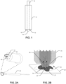
- FIG. 2A shows one aspect having an extraction device 20 with a cutting tip 22, a liquid dispensing port 24, and a liquid aspiration port 26 associated with the cutting tip 22. It should be noted that both the liquid dispensing ports 24 and the liquid aspiration port 26 are associated with the cutting tip 22 in such a way that they rotate with the cutting tip. Liquid thus dispensed during a procedure will be located at an interface between the cutting tip and the biological sample.
- the arrow in FIG. 2A represents the path of the flow of liquid from the liquid dispensing port 24 to the liquid aspiration port 26 during use.
- FIG. 2B shows a cross section of the excision device of FIG. 2A while in use.
- a biological sample 27 is disposed on a substantially planar surface 28 and a rotating 25 cutting tip 22 is brought into contact with the biological sample.
- a liquid is dispensed from the liquid dispensing ports 24 associated with the cutting tip 22 to provide liquid at the interface between the cutting tip 22 and the biological sample 27.
- Biological material is disrupted from the biological sample and is mixed with the liquid at the interface.
- the liquid and biological material mixture is aspirated from the interface via the liquid aspiration port 26.
- Arrows 29 show the liquid and the biological material being aspirated through the liquid aspiration port 26 and through the extraction device.
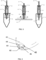
- the liquid dispensing port and the liquid aspiration port are operable to function simultaneously. It is noted that numerous designs can be utilized to achieve such functionality, and any such design is considered to be within the present scope. For example, in one aspect separate pumps can be utilized to simultaneously pump fluid out of the liquid dispensing port and aspirate liquid in through the liquid aspiration port. In other aspects, a single pump can be utilized having sufficient fluidics to allow simultaneous functionality. In one exemplary aspect shown in FIG. 3 , the internal configuration of the extraction tool can allow such simultaneous functionality. In the left panel of FIG. 3 , an extraction device 30 is positioned into a liquid holding vessel 31 to contact a liquid 32. A plunger 33 creating a seal within the extraction device 30 is depressed in a direction toward the liquid dispensing vessel 32.
- This depression causes the liquid 32 to move through a liquid dispensing port and an associated dispensing channel 34 to fill a liquid dispensing reservoir 35 within the extraction tool.
- the negative pressure created by the movement of the plunger 33 thus fills the liquid dispensing reservoir 35 with liquid.
- the extraction tool 30 is then placed against a biological sample on a substantially planar surface and rotated to disrupt biological material. While the device is rotating, the plunger 33 can be withdrawn in a direction away from the substantially planar surface 36 in order to create positive pressure in the liquid dispensing reservoir 35. This positive pressure dispenses liquid through the dispensing channel 34 and out of the liquid dispensing port at the interface 37 between the biological sample and the excision device.
- the withdrawal of the plunger 33 causes a negative pressure within a liquid aspiration reservoir 38 that causes liquid at the interface 37 to be aspirated through the liquid aspiration port and associated aspiration channel 39 to thus fill the liquid aspiration reservoir with liquid and disrupted biological material.
- the right panel of FIG. 3 shows the plunger 33 being depressed toward the cutting tip 40, thus producing a positive pressure in the liquid aspiration reservoir 38 and expelling the liquid and biological material into a liquid holding vessel 31.
- the liquid holding vessel can be the same or different from the liquid holding vessel from which the extraction device was filled.
- the various components of the excision device can be made from a variety of materials such as metals, polymers, rubbers, and the like.
- the seals can be made from a compliant material such as soft plastic or rubber
- the syringe tubes and cutting tip can be made of rigid materials such as, for example, hard plastic or metal
- the plunger can be made from a moderately compliant material. It can be useful for materials that will be in contact with liquid to have some degree of non-reactivity toward the liquid being used.
- FIG. 4 shows an extraction device housing 42 into which a rotatable cutting tip 44 is coupled.
- the cutting tip has at least one side-oriented opening 46 having an associated cutting bit 48.
- the cutting bit protrudes slightly from the underside surface 49 of the cutting tip 44.
- the broken circular cutting tip 44 functions effectively as a retaining "dam".
- Liquid is dispensed out of a liquid dispensing port 45 positioned in the housing 42.
- the liquid enters the "dam" through the opening 46, as well as between the underside surface 49 and the support substrate such as a slide.
- the liquid is then aspirated through the center of the cutting tip in proximity to the cutting bit 48 (aspiration holes not shown).
- the material such as biological material
- the cutting tip can lack an opening, and the liquid will primarily be drawn into the interior of the cutting tip 44 between the underside surface 49 and the support substrate. Such a design may minimize the loss of disrupted material on the support substrate surface.
- the size of the cutting tip can also vary widely depending on the desired use of the device. As such, any size of cutting tip is considered to be within the present scope. In one aspect, however, the cutting tip is sized to disrupt an area of biological material of from about 10 ⁇ m in size to about 1 mm in size. In another aspect, the cutting tip is sized to disrupt an area of biological material of from about 100 ⁇ m in size to about 250 ⁇ m in size.
- the present disclosure includes systems, devices, and methods for dissecting specific areas of interest from slide mounted biological material, such as tissue sections, and recovering tissue fragments for downstream biochemical analysis.
- an extraction device can be utilized as has been described herein to facilitate such dissections.
- a system including the extraction device can further include a platform to hold a substantially planar substrate such as a slide and move it in both X and Y axis directions.
- the system can further include a head piece positioned above the slide, which is capable of Z-axis movement to which the extraction device is coupled.
- the extraction device can displace very specific regions of biological material from the slide surface.
- a microscope can be positioned below the slide in an orientation to allow viewing of the cutting process.
- specialized software can be incorporated to designate an area of interest to be displaced.
- a specialized cutting bit can be similar to a mill bit in that rotational movement of the bit displaces material from a sample or from a surface.
- the cutting bit includes a liquid dispensing port and a liquid aspirating port
- the cutting bit is capable of simultaneously dispensing and aspirating liquid directly on the cutting surface in order to recover displaced fragments of biological material in the aspirated liquid.
- the cutting bit can be a modified syringe where the seal of the syringe plunger divides the syringe body into two chambers, one on either side of the plunger seal.
- liquid from the plunger side chamber is displaced and routed through channels on the outside of the syringe body and dispensed on the slide in the immediate vicinity of the cutting tip, which is located on the opposite end of the syringe body from the plunger.
- the action of withdrawing the plunger also aspirates the dispensed liquid from the slide into the syringe chamber in the syringe body.
- the cutting bit is rotated as well as moved in X and Y directions on the slide surface, displacing tissue fragments.
- tissue is cut from the slide surface it is picked up by the flow of liquid and captured by the cutting bit.
- the plunger can be depressed to expel the cutting fluid into a tube and thus allow recovery of the cut and aspirated tissue fragments. (See for example, FIG. 3 ). Multiple sizes of cutting bits can allow either more precise or more rapid cutting. Of course such a syringe-type embodiment is merely exemplary, and should not be seen as limiting.
- a system for selectively extracting biological material from a biological sample includes an extraction device 52 positioned to operationally face a support substrate 54 and to engage a biological sample disposed on the support substrate 54.
- the support substrate 54 can be any substrate capable of supporting the biological sample and functioning as outlined herein. Non-limiting examples can include microscope slides, clamps, Petri dishes, solid support surfaces, and the like.
- the support substrate can be at least substantially planar.
- the support substrate can be transparent or translucent. Such a transparent substrate allows viewing of the cutting procedure from beneath the substrate.
- the system also includes a motor 56 operationally coupled to the extraction device 52.
- the motor is configured to rotate a cutting tip 57. Any motor capable of such rotation is contemplated, and any such is considered to be within the present scope. Such motors can include single speed, variable speed, reversible, and the like, including combinations thereof.
- the motor 56 can be operationally coupled to the extraction device 52 via any functional type of connection, including belts, direct drive, gears, and the like.
- the system also includes a fluidics system 55 coupled to the extraction device 52 that is operable to deliver fluid to the liquid dispensing port and withdraw fluid from the liquid removal port (not shown).
- the fluidics system 55 can be incorporated into the extraction device 52 as is, for example, described herein. In other aspects, the fluidics system 55 can be separate from the extraction device and be fluidically coupled thereto.
- the system includes a positional movement system 53 coupled to the extraction device 52 and operable to move either the cutting tip 57 of the extraction device 52 relative to the support substrate 54 or the support substrate 54 relative to the cutting tip 57.
- 53a shows a positional movement system coupled to the extraction device 52
- 53b shows a positional movement system coupled to the support substrate 54.
- a given system can have either or both of these positional movements systems.
- the positional movement system can move the extraction device, the support substrate, or both the extraction device and the support substrate relative to one another.
- the positional movement system can be under manual control or automatic control. In one aspect, for example, the positional movement system can be under manual control. In such cases the user can have control of the axial movement (e.g.
- FIG. 5 shows an inverted microscope 58 or other imaging device positioned to observe the extraction procedure from beneath the support substrate 54.
- the user can also have control over Z-axis positioning of the cutting bit such that the bit can be lowered onto a specific region of the biological sample utilizing a positional movement system such as shown at 53a. Following cutting of a region, the cutting bit can be raised and moved to a second region, then a third region, etc.
- Bit pressure on the support substrate can be controlled by a variety of mechanisms. In one aspect, such control can be imparted by the weight of the instrument head, which rides on and thus is regulated by tension such as, for example, spring tension.
- the rotation of the cutting bit can be controlled by a motor coupled to the cutting bit.
- withdraw and depression of the plunger can be controlled by a Z-axis actuator.
- the rate of plunger withdraw is timed to the rate of X and Y axis movement; the faster the rate of travel in the X and Y axis, the faster the rate of plunger withdraw. It is also possible to cut and recover tissue without X and Y movement simply by lowering the bit on a region. In this case, the plunger will be withdrawn slightly as the bit makes contact with the slide, but further plunger withdraw can be dependent on X and Y movement.
- the positional movement system can be moved automatically.
- an automatic manipulation system 55 can be functionally coupled to the positional movement system 53a, b.
- Such an automatic manipulation system can automatically move the extraction device and/or the support substrate relative to one another.
- the automatic manipulation system can be a computer control source or other processing system.
- a processing system can be functionally coupled to the automatic manipulation system. The processing system can thus be operable to identify and locate a predetermined region of biological material to be extracted from a biological sample and to move the cutting tip and/or support substrate relative to one another to extract the biological material via the automatic manipulation system. It is also contemplated that a highly automated multiple slide capacity version of the system in which movement in all three axis will be computer controlled can be implemented, as will the loading of the cutting fluid liquid and the recovery of fragments from the cutting bit.
- a visualization system 58 can be positioned to provide a visual display of a biological sample placed on the support substrate.
- Any visualization system known is considered to be within the present scope, non-limiting examples of which include digital imagers, optical imagers, microscopes, inverted microscopes, and the like, including combinations thereof.
- the visualization system is an inverted microscope positioned to provide the visual display from a side of the support substrate opposite the cutting tip. In other words, the inverted microscope allows the viewing of the cutting procedure from beneath a transparent support substrate.
- the visualization system is operable to provide a real time visual display of the cutting tip during an extraction procedure.
- the visual system also allows the ability to indicate digitally a region or area of interest to be processed or excised on the live image of a biological sample. This area of interest can then be optionally locked in position relative to the biological sample section and moved with the live image as the slide is moved under the cutting bit.
- the area of interest can be generated for a different biological sample section from a series of sections cut from the same sample (e.g. a tissue block). Because the sections are cut very thin, neighboring tissue sections have a very similar in overall morphology, although they may not be identical.
- the advantage of generating the area of interest from a neighboring section is that one section can be stained with a first type of stain and cover slipped for optimal viewing, while the neighboring section is stained with a second type of stain but not cover slipped for optimal recovery and downstream biochemical testing.
- the system can be used to dissect and recover specific areas of tissue from slide mounted tissue sections for further biochemical analysis.
- additional uses for the system are contemplated.
- FISH Fluorescent In Situ Hybridization
- the system can be used to dissect thin layers of biological material other than tissue sections immobilized on standard laboratory slides.
- layers derived from biological material either randomly spread or cultured on the slide surface can be processed.
- the biological material can be immobilized on a transparent surface other than a slide, for example a tissue culture dish.
- the layers are non-biological material, for example thin geological or semiconductor layers.
- microdissection procedures can be carried out on sequentially sliced sections of tissue.
- Tissue sections on slides are typically very thin (for example 3 microns) and are cut sequentially from the same block of tissue.
- the block of tissue is chemically fixed, dehydrated, and embedded in paraffin wax.
- Sequentially cut tissue sections are termed neighboring tissue sections, and they are very similar, but not identical in overall morphology.
- FFPE formalin fixed, paraffin embedded
- Tumors are generally heterogeneous in composition, requiring dissection of neoplastic tissue from the surrounding non-neoplastic tissue in order to obtain a sufficiently high percentage of tumor cells for optimal analytic sensitivity of downstream testing.
- dissection can be accomplished using a laser cutting tool or a variety of mechanical cutting tools under direct microscopic visualization (collectively termed “microdissection”), or by gross visualization of an area previously identified and marked under a microscope (“macrodissection”).
- Laser directed methods collectively termed laser capture microdissection (LCM), include laser cutting and either thermoplastic film or "catapulting" to capture areas of tissue selected by real-time microscopic visualization.
- LCM is spatially very precise allowing capture of areas down to a few microns in size, but the technique has several drawbacks: the equipment is very expensive, and the procedure is very time consuming because it requires real-time histologic interpretation by the pathologist. The latter drawback may in fact be the main reason why LCM has not been adopted by most laboratories.
- Macrodissection is done under a microscope using needles, sonic chisels, or other scraping tools.
- the precision can approach that of LCM, but the equipment can be fairly expensive and like LCM the technique requires significant operator time and expertise particularly if the area has not been pre-selected by a pathologist.
- Macrodissection is done with the unaided eye using devices such as scalpels; the process is relatively easy and equipment expenses are often negligible, but precision is typically a few millimeters or more.
- Macrodissection is currently a popular method in many laboratories with a high test volume, because the procedure can be performed by a laboratory technologist without any training in histopathology. The pathologist simply circles the area to be tested on a slide and the laboratory technologist performs the actual macrodissection as well as downstream testing on a companion slide from the same FFPE tissue block.
- the present devices and techniques overcome many of these problems and provide a system whereby such processes can be automated.
- the present device is relatively inexpensive to produce and operate, and can semi-automate or fully automate slide based tissue macrodissection and provide spatial resolution (smallest region recoverable) of 1 mm or less and positional accuracy of 0.1 mm or less (closer to microdissection than to manual macrodissection).
- the various devices and systems described herein can be incorporated with a software system that allows a user to indicate an area of interest on a digital image of a tissue section immobilized on a particular slide of a series of slides.
- the software system then can transfer that area of interest to the analogous location of a digital image of a tissue section immobilized on an adjacent slide (directly adjacent or further along in the slide series), and generate area of interest location information to a system for disrupting and extracting the tissue from the slide.
- a slide based process and software system can function as follows: A user can specify an area of interest on a tissue section immobilized on a first slide, possibly by generating a digital annotation on a digital image of the tissue section.
- the area of interest can be digitally transferred to an analogous region of a neighboring tissue section on another slide, or in some cases the area of interest can be transferred to a separate section on the same slide.
- the software specifies the X and Y coordinates of the area of interest relative to the slide and generates location information.
- the software can then direct the extraction device to disrupt and recover the tissue located at the area of interest on the second slide, while the morphology of the tissue is maintained on the first slide.
- two slides each supporting a sequential tissue section from the same tissue sample are treated with different stains.
- One stain is used for visualization of the tissue section and the second stain is more compatible with tissue recovery and downstream biochemical analysis.
- H&E stain could be used for visualization slide
- Analine Blue stain could be used for tissue recovery slide.
- a high resolution digital image can be generated from the tissue visualization slide using a digital or other microscope.
- a user such as a pathologist outlines an area of interest on the microscopic digital image from the tissue section visualization slide.
- the software also generates a digital image silhouette of the tissue section and positions the area of interest generated by the pathologist relative to the tissue section silhouette.
- digital images in some cases lower resolution digital images, of the entire slide including the tissue sections and slide edges can be generated from both the visualization and tissue recovery slides, in one aspect by a standard digital camera.
- the software can generate digital image silhouettes of the tissue sections and position them relative to the edges of the slide. It is also possible to incorporate bar code reading software algorithms for database interactions.
- the tissue section silhouettes from the low and high resolution visualization slide images are aligned by the operator or using image recognition algorithms and the location of the area of interest is transferred to the recovery tissue section image.
- the software then generates location information that is sent to the material extraction system, which allows it to recover tissue corresponding to the area of interest.
- a digital camera or barcode reader mounted on the extraction device checks bar codes on the slides and tubes to verify correct placement. After extraction is complete, the digital camera takes a picture of the tissue section to document the tissue region that was recovered.
- such a software implementation can include a variety of software modules, such as command modules, image recognition modules, mechanical movement modules, barcode reading modules, graphical user interface modules, and the like.
- software and software modules would be resident in hardware within the extraction system or in an associated computer system or network.
- FIG. 6a shows an example of a tissue section image 91 captured by a digital microscope and displayed on a computer screen.
- a composite image 93 of the tissue section stitched together from a series of individual images generated by the digital microscope.
- the area currently being viewed live is indicated 92 on the composite image.
- FIG. 6b shows a digitally indicated area of interest superimposed on the live image.
- the areas of interest can be of any size and shape, larger or smaller than the field of view, and multiple areas of interest can be created on a particular tissue section.
- the area of interest is "locked” in position relative to the tissue section such that when the tissue section is moved in the X and Y axis directions, the area of interest moves with the live image ( FIG. 6c ). In this way, the area of interest can guide the user to microdissect the proper region of tissue 95 using the cutting tip 96. Once complete, the area of interest is now devoid of tissue 95, which has been recovered by the cutting tip ( FIG. 6D ).
- the software can generate an area of interest from a neighboring tissue section.
- the advantage of generating the area of interest from a neighboring section is the preparation conditions of the neighboring section can be chosen for optimal viewing. For example, the use of a glued on coverslip, and the use of multiple tissue stains, which provide significantly more biological information, but are inhibitory to the downstream biochemistries typically performed on microdissected tissue.
- FIG. 7a shows an area of interest 94 positioned on an image from a cover slipped H&E stained tissue section 99.
- FIG. 7b shows an image of a neighboring tissue section 91 optimized for tissue microdissection (for example stained with a non-inhibitory stain such as Analine Blue and not cover slipped).
- a copy of the area of interest 94 has been positioned on the corresponding region of tissue, as determined by tissue morphology shared by the neighboring tissue sections.
- FIG. 8 A material extraction device is shown in FIG. 8 .
- Various parts are made using an injection molding or sinter molding process and therefore are made of plastic or fused metal powder. The components are listed below.
- Example 2 Material extraction system.
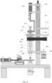
- FIG. 9 A material extraction system is shown in FIG. 9 .
- the instrument head assembly 161 is mounted on a set of rails 162, which are mounted perpendicularly to the plane of the slide. Z-axis movement of the instrument head on the rails is controlled by a linear actuator 163, which controls contact of the cutting bit with the slide. The pressure of the cutting bit on the slide surface is created by the weight of the instrument head assembly riding on an adjustable spring 164.
- the instrument head assembly contains a rotational assembly with the axis of rotation oriented vertically and passing through the center of focus of the digital camera.
- the rotational assembly is comprised of an outer cylinder 165 with a Morris taper 166 on the axis of rotation that matches the taper of the cutting bit.
- the outer cylinder is supported by bearings 167, which are held mounted in the instrument head assembly.
- the rotational assembly is also comprised of an inner cylinder 168, which is movable along the axis of rotation by a linear actuator 169.
- the linear actuator is mounted to the instrument head assembly and is rotationally decoupled from the rotational assembly by a bearing 170.
- the inner cylinder contains a grasping cassette 171, which allows reversible grasping of the cutting bit plunger 101. Control of the grasping cassette is via a rod 172, depression of which releases the grip of the grasping cassette on the plunger of the cutting bit and ejects the cutting bit from the Morris taper. Rotational force of the rotational assembly is generated by a motor 173, which is mounted on the instrument head assembly.
Landscapes
- Life Sciences & Earth Sciences (AREA)
- Health & Medical Sciences (AREA)
- Chemical & Material Sciences (AREA)
- General Physics & Mathematics (AREA)
- Pathology (AREA)
- Physics & Mathematics (AREA)
- Immunology (AREA)
- Analytical Chemistry (AREA)
- Biochemistry (AREA)
- General Health & Medical Sciences (AREA)
- Engineering & Computer Science (AREA)
- Biomedical Technology (AREA)
- Molecular Biology (AREA)
- Hydrology & Water Resources (AREA)
- Hematology (AREA)
- Urology & Nephrology (AREA)
- Food Science & Technology (AREA)
- Medicinal Chemistry (AREA)
- Sampling And Sample Adjustment (AREA)
- Investigating Or Analysing Materials By Optical Means (AREA)
- Microscoopes, Condenser (AREA)
- Measuring Or Testing Involving Enzymes Or Micro-Organisms (AREA)
Applications Claiming Priority (3)
| Application Number | Priority Date | Filing Date | Title |
|---|---|---|---|
| US201161461925P | 2011-01-24 | 2011-01-24 | |
| US201161491829P | 2011-05-31 | 2011-05-31 | |
| PCT/US2011/061075 WO2012102779A2 (en) | 2011-01-24 | 2011-11-16 | Devices, systems, and methods for extracting a material from a material sample |
Publications (3)
| Publication Number | Publication Date |
|---|---|
| EP2668487A2 EP2668487A2 (en) | 2013-12-04 |
| EP2668487A4 EP2668487A4 (en) | 2017-09-27 |
| EP2668487B1 true EP2668487B1 (en) | 2024-11-06 |
Family
ID=46581327
Family Applications (1)
| Application Number | Title | Priority Date | Filing Date |
|---|---|---|---|
| EP11857029.0A Active EP2668487B1 (en) | 2011-01-24 | 2011-11-16 | Devices, systems, and methods for extracting a material from a material sample |
Country Status (7)
| Country | Link |
|---|---|
| US (3) | US10866170B2 (enExample) |
| EP (1) | EP2668487B1 (enExample) |
| JP (2) | JP6039872B2 (enExample) |
| KR (1) | KR101858780B1 (enExample) |
| CN (1) | CN103443609B (enExample) |
| CA (1) | CA2825612C (enExample) |
| WO (1) | WO2012102779A2 (enExample) |
Families Citing this family (35)
| Publication number | Priority date | Publication date | Assignee | Title |
|---|---|---|---|---|
| WO2014065101A1 (ja) * | 2012-10-24 | 2014-05-01 | オリンパス株式会社 | 基板回収装置 |
| US20140125790A1 (en) * | 2012-11-08 | 2014-05-08 | Wisconsin Alumni Research Foundation | Device And Method For Three Dimensional Imaging Of Biological Sample |
| US9946953B2 (en) | 2013-05-10 | 2018-04-17 | Koninklijke Philips N.V. | Apparatus and method for processing images of tissue samples |
| GB2513916B (en) * | 2013-05-10 | 2016-03-02 | Pathxl Ltd | Identifying a Tissue Boundary of a Tumour Region of a Tissue Sample |
| US9625355B2 (en) | 2014-12-01 | 2017-04-18 | General Electric Company | Extraction of materials from regions of interest in a sample |
| EP3250901A1 (en) | 2015-01-31 | 2017-12-06 | Roche Diagnostics GmbH | Systems and methods for meso-dissection |
| WO2016120434A1 (en) * | 2015-01-31 | 2016-08-04 | Roche Diagnostics Gmbh | Systems and methods for meso-dissection |
| JP6759550B2 (ja) * | 2015-03-04 | 2020-09-23 | ソニー株式会社 | 情報処理装置、プログラム、情報処理方法及び観察システム |
| WO2017009337A1 (en) * | 2015-07-16 | 2017-01-19 | Koninklijke Philips N.V. | Information transformation in digital pathology |
| CN205785992U (zh) * | 2016-05-20 | 2016-12-07 | 青海师范大学 | 一种叶表皮刮削仪 |
| CN106023225B (zh) * | 2016-05-30 | 2019-03-08 | 武汉沃亿生物有限公司 | 生物样本显微成像的自动修改成像区间方法 |
| EP3519005B1 (en) * | 2016-10-03 | 2023-09-13 | Terumo BCT, Inc. | Centrifugal fluid separation device |
| EP3532985B1 (en) | 2016-10-28 | 2023-07-12 | Beckman Coulter, Inc. | Substance preparation evaluation system |
| US10876933B2 (en) | 2016-11-09 | 2020-12-29 | Ventana Medical Systems, Inc. | Automated tissue dissection instrument and methods of using the same |
| US10758410B2 (en) | 2017-10-13 | 2020-09-01 | Surgical Design Corporation | Surgical hand piece with ultrasonic knife |
| US10709603B2 (en) | 2017-10-13 | 2020-07-14 | Surgical Design Corporation | Dual lumen surgical hand-piece with ultrasonic knife |
| US11207094B2 (en) * | 2017-11-22 | 2021-12-28 | Surgical Design Corporation | Single piece connecting member and work tip for surgical hand piece |
| CN107988208A (zh) * | 2017-12-26 | 2018-05-04 | 东莞赛尔生物科技有限公司 | 用于从ffpe组织切片中提取样品的取样装置及取样方法 |
| CN108510845B (zh) * | 2018-03-17 | 2021-01-15 | 长江大学 | 一种地质沉积相学习用辅助工具 |
| KR20210003287A (ko) * | 2018-06-21 | 2021-01-11 | 게노믹 헬쓰, 인코포레이티드 | 자동화된 샘플 준비 시스템 및 그 어플리케이션들 |
| US11573156B2 (en) * | 2019-01-15 | 2023-02-07 | Westinghouse Electric Company Llc | Minimally invasive microsampler for intact removal of surface deposits and substrates |
| EP3754322A1 (en) * | 2019-06-18 | 2020-12-23 | Xyall B.V. | Tissue sample dissection apparatus |
| EP3761032A1 (en) | 2019-07-03 | 2021-01-06 | Xyall B.V. | Determining region(s) for tissue dissection in pathology slides |
| TW202111303A (zh) | 2019-07-24 | 2021-03-16 | 捷絡生物科技股份有限公司 | 組織切片系統 |
| KR20220033093A (ko) * | 2020-09-08 | 2022-03-16 | 바이오뱅크 주식회사 | 반응효율이 향상된 휴대용 실시간 유전자 분석시스템 및 이에 사용되는 그라인딩유닛 |
| US20240027305A1 (en) * | 2020-09-22 | 2024-01-25 | Xyall BV. | Method, tool and apparatus for dissecting and transferring biological material |
| EP3971549A1 (en) | 2020-09-22 | 2022-03-23 | Xyall B.V. | Method, tool and apparatus for dissecting and transferring biological material |
| CN116368363A (zh) * | 2020-11-06 | 2023-06-30 | 赛默环境设备有限责任公司 | 用于自动收集气溶胶颗粒的系统和方法 |
| CN113358432A (zh) * | 2021-05-31 | 2021-09-07 | 东南大学 | 一种用于组织切片的微区样本采集装置 |
| EP4352483B1 (en) | 2021-06-11 | 2025-01-29 | Xyall B.V. | Apparatus comprising an interface for detachable coupling of a dissection tool |
| EP4177662A1 (en) | 2021-11-09 | 2023-05-10 | Roche Diagnostics GmbH | Instrument for automatically dissecting a biological specimen on a slide |
| WO2023137340A1 (en) * | 2022-01-11 | 2023-07-20 | TriMetis Life Sciences, LLC | Tissue coring and analysis system |
| CN121014059A (zh) | 2023-04-14 | 2025-11-25 | Xyall私人有限公司 | 解剖设备 |
| DE102023126498A1 (de) * | 2023-09-28 | 2025-04-03 | Analytik Jena Gmbh+Co. Kg | Vorrichtung zur Gewinnung von Probenmaterial |
| CN119000154B (zh) * | 2024-10-23 | 2025-01-24 | 绵阳师范学院 | 一种植物根系分泌物提取装置及方法 |
Citations (1)
| Publication number | Priority date | Publication date | Assignee | Title |
|---|---|---|---|---|
| US20100224013A1 (en) * | 2009-03-05 | 2010-09-09 | Van Berkel Gary J | Method and system for formation and withdrawal of a sample from a surface to be analyzed |
Family Cites Families (93)
| Publication number | Priority date | Publication date | Assignee | Title |
|---|---|---|---|---|
| US281695A (en) | 1883-07-24 | Combe | ||
| US3238889A (en) | 1963-06-03 | 1966-03-08 | Aero Spray Inc | Piston drive mechanism |
| JPS477506Y1 (enExample) * | 1967-03-20 | 1972-03-21 | ||
| US3732858A (en) * | 1968-09-16 | 1973-05-15 | Surgical Design Corp | Apparatus for removing blood clots, cataracts and other objects from the eye |
| US3906954A (en) * | 1973-09-14 | 1975-09-23 | Nasa | Ophthalmic liquifaction pump |
| US4320761A (en) * | 1979-02-06 | 1982-03-23 | Haddad Heskel M | Surgical device for excision of tissue |
| JPS6145957A (ja) | 1984-08-10 | 1986-03-06 | Hitachi Ltd | 組織物抽出装置 |
| US4679446A (en) | 1985-09-09 | 1987-07-14 | Baxter Travenol Laboratories, Inc. | Multi-volume displacement pipette |
| JPS62292144A (ja) | 1986-06-12 | 1987-12-18 | 旭光学工業株式会社 | 内視鏡用生検鉗子 |
| US5267955A (en) * | 1990-05-10 | 1993-12-07 | Lake Region Manufacturing Company, Inc. | Atherectomy device |
| US5218645A (en) | 1991-03-29 | 1993-06-08 | Cell Analysis Systems, Inc. | Method and apparatus for separating cell objects for analysis |
| US5428690A (en) | 1991-09-23 | 1995-06-27 | Becton Dickinson And Company | Method and apparatus for automated assay of biological specimens |
| JP3075315B2 (ja) | 1992-02-06 | 2000-08-14 | オリンパス光学工業株式会社 | 顕微鏡システム |
| JPH07184908A (ja) | 1993-12-27 | 1995-07-25 | Sumitomo Bakelite Co Ltd | 組織サンプル採取管付き外科手術用具 |
| US6251516B1 (en) | 1994-03-01 | 2001-06-26 | The United States Of America As Represented By The Department Of Health And Human Services | Isolation of cellular material under microscopic visualization |
| US5843657A (en) | 1994-03-01 | 1998-12-01 | The United States Of America As Represented By The Department Of Health And Human Services | Isolation of cellular material under microscopic visualization |
| US5843644A (en) | 1994-03-01 | 1998-12-01 | The United States Of America As Represented By The Secretary Of The Department Of Health And Human Services | Isolation of cellular material under microscopic visualization using an adhesive/extraction reagent tipped probe |
| US5456125A (en) * | 1994-03-31 | 1995-10-10 | Millipore Corporation | Membrane cutter and retriever |
| US5511556A (en) | 1994-04-11 | 1996-04-30 | Desantis; Stephen A. | Needle core biopsy instrument |
| CA2198544A1 (en) | 1996-03-21 | 1997-09-22 | Bayer Corporation | Apparatus for simultaneous aspiration and dispensation of fluids |
| EP0926998B8 (en) | 1997-06-23 | 2004-04-14 | Koninklijke Philips Electronics N.V. | Image guided surgery system |
| WO1999015875A1 (en) | 1997-09-25 | 1999-04-01 | Macquarie Research Ltd. | Apparatus for removing a sample from an array of samples and a cutting tool for use with that apparatus |
| DE19818425A1 (de) | 1997-10-18 | 1999-07-15 | Malte Dr Med Boehm | Vorrichtung zur Handhabung von Proben für die membrangestützte Mikrodissektion |
| US7473401B1 (en) | 1997-12-04 | 2009-01-06 | Mds Analytical Technologies (Us) Inc. | Fluidic extraction of microdissected samples |
| US5925834A (en) | 1997-12-16 | 1999-07-20 | Waters Investments Limited | Autosampler syringe with compression sealing |
| US6090572A (en) | 1998-06-26 | 2000-07-18 | Biostar, Incorporated | Filtration and extraction device and method of using the same |
| KR100271053B1 (ko) | 1998-09-21 | 2000-11-01 | 이정용 | 현미경을 이용한 종양세포 미세 절제장치 |
| AUPP930099A0 (en) | 1999-03-19 | 1999-04-15 | Campbell Corporation Pty Ltd | Improvements in apparatus and method for removing samples |
| DE19932032C2 (de) | 1999-07-09 | 2003-07-24 | Eppendorf Ag | Vorrichtung zur Mikro-Dissektion von Gewebe |
| TW451193B (en) * | 1999-11-30 | 2001-08-21 | Via Tech Inc | A method to determine the timing setting value of dynamic random access memory |
| US6342143B1 (en) | 2000-01-06 | 2002-01-29 | Carnegie Mellon University | Cutting tool for multiple sample retrieval from gelatinous material |
| US20010031981A1 (en) * | 2000-03-31 | 2001-10-18 | Evans Michael A. | Method and device for locating guidewire and treating chronic total occlusions |
| US6565728B1 (en) | 2000-06-08 | 2003-05-20 | Elchrom Scientific | Gel cutting and recovering device |
| US6790636B1 (en) | 2000-06-14 | 2004-09-14 | The United States Of America As Represented By The Department Of Health And Human Services | Rapid fluorescent labeling of tissue for microdissection using fluorescent specific binding agents |
| US20020090122A1 (en) | 2000-11-03 | 2002-07-11 | Baer Thomas M. | Road map image guide for automated microdissection |
| ATE499989T1 (de) | 2000-12-18 | 2011-03-15 | Protedyne Corp | Extrudieren von gel für gel elektrophorese |
| US20020091441A1 (en) | 2001-01-05 | 2002-07-11 | Guzik Donald S. | Focused beam cutting of materials |
| US6602071B1 (en) | 2001-01-13 | 2003-08-05 | M. Edmund Ellion | Hand-held self-contained cleaning system |
| DE10102034A1 (de) | 2001-01-18 | 2002-08-08 | Leica Microsystems | Objektträger, Mikrodissektionseinrichtung mit Objektträger und Verfahren zur Mikrodissektion |
| US6817256B2 (en) | 2001-02-27 | 2004-11-16 | Alfa Wassermann, Inc. | Pipette sampling system |
| US20040053326A1 (en) | 2001-03-14 | 2004-03-18 | Emmert-Buck Michael R. | Transfer microdessection |
| CA2345911C (en) | 2001-05-02 | 2009-02-17 | Joel S. Harris | Sampling apparatus for material collection |
| KR100422278B1 (ko) | 2001-05-04 | 2004-03-10 | 박용원 | 유전자 분석용 디엔에이 함유 겔 단편 자동 추출장치 및그것을 채용한 유브이 일루미네이터 |
| US6702990B1 (en) | 2002-02-05 | 2004-03-09 | The Gel Company | Spot picker |
| US20030179916A1 (en) | 2002-02-06 | 2003-09-25 | Magnuson Terry R. | High-throughput cell identification and isolation method and apparatus |
| US7468161B2 (en) | 2002-04-15 | 2008-12-23 | Ventana Medical Systems, Inc. | Automated high volume slide processing system |
| ES2556242T3 (es) | 2002-04-26 | 2016-01-14 | Ventana Medical Systems, Inc. | Aparato de patología molecular automatizado que tiene plataformas de portaobjetos fijas |
| US20040142488A1 (en) * | 2002-07-15 | 2004-07-22 | Gierde Douglas T. | Method and device for extracting an analyte |
| EP1521637B1 (en) | 2002-07-15 | 2011-10-19 | Phynexus, Inc. | Extraction column device |
| JP2004069666A (ja) * | 2002-08-08 | 2004-03-04 | Tsuerun:Kk | パラフィン切片の部分切り取りと整列させる技術 |
| DE10254229B4 (de) | 2002-11-20 | 2004-10-28 | P.A.L.M. Microlaser Technologies Ag | Positioniervorrichtung zum Positionieren einerAuffangvorrichtung eines Laser-Mikrodissektionssystems |
| US7850912B2 (en) * | 2003-05-14 | 2010-12-14 | Dako Denmark A/S | Method and apparatus for automated pre-treatment and processing of biological samples |
| JP3877213B2 (ja) | 2003-02-07 | 2007-02-07 | 康彦 北山 | アレイブロック作成方法とこれに使用される組織くりぬき装置 |
| US7025732B2 (en) | 2003-02-25 | 2006-04-11 | Ethicon Endo-Surgery, Inc. | Biopsy device with variable speed cutter advance |
| US7185551B2 (en) | 2003-05-22 | 2007-03-06 | Schwartz H Donald | Pipetting module |
| US20080235055A1 (en) | 2003-07-17 | 2008-09-25 | Scott Mattingly | Laboratory instrumentation information management and control network |
| US8034003B2 (en) * | 2003-09-11 | 2011-10-11 | Depuy Mitek, Inc. | Tissue extraction and collection device |
| KR100498275B1 (ko) | 2003-09-16 | 2005-06-29 | 주식회사 정우인터내셔날 | 미세 절제 시스템용 수집함 홀더 및 이를 채용한 미세절제 시스템용 스테이지 장치 |
| KR100536462B1 (ko) | 2003-09-16 | 2005-12-14 | 주식회사 정우인터내셔날 | 미세 절제 시스템의 스테이지 장치 이동용 매니퓰레이터 |
| IE20030856A1 (en) * | 2003-11-14 | 2005-06-15 | Enfer Technology Ltd | Sample homogeniser |
| US7641859B2 (en) | 2004-02-11 | 2010-01-05 | Matrix Technologies Corporation | Pipette tip mounting and ejection assembly and associated pipette tip |
| CN101018502A (zh) | 2004-04-28 | 2007-08-15 | 塞西斯医药股份有限公司 | 非侵入式分析仪取样探针接口方法和装置 |
| JP2007209360A (ja) | 2004-07-29 | 2007-08-23 | Nikkyo Technos Kk | 試料採取具 |
| US7276032B2 (en) | 2004-09-29 | 2007-10-02 | Ethicon Endo-Surgery, Inc. | Biopsy apparatus and method |
| RU2305270C2 (ru) | 2005-05-18 | 2007-08-27 | Андрей Алексеевич Климов | Способ флуоресцентной наноскопии (варианты) |
| DE102005061561A1 (de) | 2005-12-22 | 2007-06-28 | P.A.L.M. Microlaser Technologies Ag | Laser-Mikrodissektionsverfahren, Steuersystem für eine Laser-Mikrodissektionsvorrichtung und Trägervorrichtung |
| DE102006000934A1 (de) | 2006-01-05 | 2007-07-12 | P.A.L.M. Microlaser Technologies Ag | Mikrodissektionsverfahren und Mikrodissektionssystem |
| FR2895920B1 (fr) | 2006-01-06 | 2008-04-18 | Gilson Sas Soc Par Actions Sim | Pipette multivolumes. |
| JP2007286697A (ja) | 2006-04-12 | 2007-11-01 | Mastercard Internatl Japan Inc | 支払い処理支援装置及び支払い処理支援方法 |
| DE102006034245C5 (de) | 2006-07-21 | 2014-05-28 | Stratec Biomedical Systems Ag | Positioniereinrichtung zur Positionierung von Pipetten |
| US7794664B2 (en) | 2006-11-16 | 2010-09-14 | Idexx Laboratories, Inc. | Pipette tip |
| US9697582B2 (en) | 2006-11-16 | 2017-07-04 | Visiopharm A/S | Methods for obtaining and analyzing images |
| TWI347176B (en) | 2006-12-21 | 2011-08-21 | Ind Tech Res Inst | Dissecting device and method for cell and tissue |
| TWI316853B (en) | 2006-12-29 | 2009-11-11 | Ind Tech Res Inst | Dissection device with tool changer |
| WO2009008843A1 (en) | 2007-07-10 | 2009-01-15 | National University Of Singapore | Apparatus for forming a tissue array |
| EP2053377A1 (de) | 2007-10-22 | 2009-04-29 | MMI GmbH | Verfahren und Vorrichtung zur dreimimensionalen Mikrodissektion |
| CN201262598Y (zh) | 2008-04-21 | 2009-06-24 | 浙江大学 | 一种伺服超声振动显微切割装置 |
| US8545517B2 (en) | 2008-06-06 | 2013-10-01 | Restoration Robotics, Inc. | Systems and methods for improving follicular unit harvesting |
| WO2010021744A1 (en) | 2008-08-21 | 2010-02-25 | California Institute Of Technology | Microscope coupled tissue sectioning system |
| CN102271595A (zh) * | 2008-11-06 | 2011-12-07 | 恩克斯特拉公司 | 用于bph的治疗的系统和方法 |
| CA2752617A1 (en) | 2009-02-13 | 2010-08-19 | Samir Mitragotri | System, method and device for tissue-based diagnosis |
| EP2425401A2 (en) | 2009-04-28 | 2012-03-07 | Koninklijke Philips Electronics N.V. | Microdissection method and information processing system |
| JP2010267092A (ja) | 2009-05-14 | 2010-11-25 | Canon Inc | 情報処理装置、情報処理方法 |
| NL1037348C2 (en) * | 2009-10-02 | 2011-04-05 | Univ Eindhoven Tech | Surgical robot, instrument manipulator, combination of an operating table and a surgical robot, and master-slave operating system. |
| US8784021B2 (en) | 2009-11-05 | 2014-07-22 | O'brien Dental Lab, Inc. | Jig device and apparatus and method of making a dental prosthesis or pattern therefor |
| WO2012068142A2 (en) | 2010-11-15 | 2012-05-24 | Tissuevision, Inc. | Systems and methods for imaging and processing tissue |
| JP2013195133A (ja) | 2012-03-16 | 2013-09-30 | Olympus Corp | 画像作成装置、画像作成方法および画像作成プログラム |
| JP6105859B2 (ja) | 2012-05-24 | 2017-03-29 | 日本無線株式会社 | 埋設物探査装置 |
| US20130344500A1 (en) | 2012-06-20 | 2013-12-26 | Aratome, LLC | Tissue adhesive substrates |
| US9798918B2 (en) | 2012-10-05 | 2017-10-24 | Cireca Theranostics, Llc | Method and system for analyzing biological specimens by spectral imaging |
| DE102012218382B4 (de) | 2012-10-09 | 2015-04-23 | Leica Microsystems Cms Gmbh | Verfahren zum Festlegen eines Lasermikrodissektionsbereichs und zugehöriges Lasermikrodissektionssystem |
| US9818190B2 (en) | 2013-03-14 | 2017-11-14 | Ventana Medical Systems, Inc. | Whole slide image registration and cross-image annotation devices, systems and methods |
| US9984457B2 (en) | 2014-03-26 | 2018-05-29 | Sectra Ab | Automated grossing image synchronization and related viewers and workstations |
-
2011
- 2011-11-16 KR KR1020137022449A patent/KR101858780B1/ko active Active
- 2011-11-16 US US13/981,541 patent/US10866170B2/en active Active
- 2011-11-16 WO PCT/US2011/061075 patent/WO2012102779A2/en not_active Ceased
- 2011-11-16 JP JP2013550465A patent/JP6039872B2/ja active Active
- 2011-11-16 CN CN201180069499.6A patent/CN103443609B/zh active Active
- 2011-11-16 EP EP11857029.0A patent/EP2668487B1/en active Active
- 2011-11-16 CA CA2825612A patent/CA2825612C/en active Active
-
2016
- 2016-11-05 JP JP2016216803A patent/JP6585577B2/ja active Active
-
2020
- 2020-11-12 US US17/096,667 patent/US20210181074A1/en active Pending
-
2023
- 2023-03-30 US US18/129,032 patent/US20230375443A1/en active Pending
Patent Citations (1)
| Publication number | Priority date | Publication date | Assignee | Title |
|---|---|---|---|---|
| US20100224013A1 (en) * | 2009-03-05 | 2010-09-09 | Van Berkel Gary J | Method and system for formation and withdrawal of a sample from a surface to be analyzed |
Also Published As
| Publication number | Publication date |
|---|---|
| CA2825612A1 (en) | 2012-08-02 |
| CN103443609A (zh) | 2013-12-11 |
| CN103443609B (zh) | 2016-01-20 |
| US20140329269A1 (en) | 2014-11-06 |
| EP2668487A2 (en) | 2013-12-04 |
| JP6039872B2 (ja) | 2016-12-07 |
| CA2825612C (en) | 2021-02-16 |
| KR101858780B1 (ko) | 2018-05-16 |
| US20210181074A1 (en) | 2021-06-17 |
| US10866170B2 (en) | 2020-12-15 |
| KR20140033340A (ko) | 2014-03-18 |
| US20230375443A1 (en) | 2023-11-23 |
| WO2012102779A2 (en) | 2012-08-02 |
| EP2668487A4 (en) | 2017-09-27 |
| JP6585577B2 (ja) | 2019-10-02 |
| JP2014504728A (ja) | 2014-02-24 |
| JP2017122710A (ja) | 2017-07-13 |
| WO2012102779A3 (en) | 2012-09-13 |
Similar Documents
| Publication | Publication Date | Title |
|---|---|---|
| US20230375443A1 (en) | Devices, systems, and methods for extracting a material from a material sample | |
| US5817032A (en) | Means and method for harvesting and handling tissue samples for biopsy analysis | |
| JP6640238B2 (ja) | 試料採取システム | |
| CN102414716B (zh) | 显微剖切方法和信息处理系统 | |
| CN1255527C (zh) | 用于构筑组织阵列的仪器 | |
| JP5244801B2 (ja) | 細胞及び/又は細胞コロニーの自動化した除去のための方法及び装置 | |
| US8464619B2 (en) | Device for dissecting thin samples and methods thereof | |
| US20190353579A1 (en) | System and method for retrieving and analyzing particles | |
| CA3053184A1 (en) | Systems and methods for automated preparation of biological specimens | |
| CN105358971A (zh) | 激光显微切割系统和用于含有核酸的样本的检查方法 | |
| US20240280596A1 (en) | Sample processing systems, methods, and devices | |
| JP7039261B2 (ja) | 組織切片の特定領域からの生体分子採取方法および装置 | |
| Ahmed | Laser microdissection: application to carcinogenesis | |
| US20190391055A1 (en) | Automated sample preparation system and applications thereof | |
| Tayade et al. | Laser capture microdissection | |
| US10494627B2 (en) | Extraction of materials from regions of interest in a sample | |
| Goyal et al. | Tissue Microarrays-A Review | |
| CN118159826A (zh) | 样本处理系统、方法和装置 | |
| TW200927061A (en) | Selecting apparatus and dividing mechanism thereof |
Legal Events
| Date | Code | Title | Description |
|---|---|---|---|
| PUAI | Public reference made under article 153(3) epc to a published international application that has entered the european phase |
Free format text: ORIGINAL CODE: 0009012 |
|
| 17P | Request for examination filed |
Effective date: 20130809 |
|
| AK | Designated contracting states |
Kind code of ref document: A2 Designated state(s): AL AT BE BG CH CY CZ DE DK EE ES FI FR GB GR HR HU IE IS IT LI LT LU LV MC MK MT NL NO PL PT RO RS SE SI SK SM TR |
|
| DAX | Request for extension of the european patent (deleted) | ||
| A4 | Supplementary search report drawn up and despatched |
Effective date: 20170829 |
|
| RIC1 | Information provided on ipc code assigned before grant |
Ipc: G01N 33/48 20060101ALI20170823BHEP Ipc: G01N 1/04 20060101AFI20170823BHEP |
|
| STAA | Information on the status of an ep patent application or granted ep patent |
Free format text: STATUS: EXAMINATION IS IN PROGRESS |
|
| 17Q | First examination report despatched |
Effective date: 20190513 |
|
| GRAP | Despatch of communication of intention to grant a patent |
Free format text: ORIGINAL CODE: EPIDOSNIGR1 |
|
| STAA | Information on the status of an ep patent application or granted ep patent |
Free format text: STATUS: GRANT OF PATENT IS INTENDED |
|
| INTG | Intention to grant announced |
Effective date: 20240126 |
|
| GRAS | Grant fee paid |
Free format text: ORIGINAL CODE: EPIDOSNIGR3 |
|
| GRAA | (expected) grant |
Free format text: ORIGINAL CODE: 0009210 |
|
| STAA | Information on the status of an ep patent application or granted ep patent |
Free format text: STATUS: THE PATENT HAS BEEN GRANTED |
|
| AK | Designated contracting states |
Kind code of ref document: B1 Designated state(s): AL AT BE BG CH CY CZ DE DK EE ES FI FR GB GR HR HU IE IS IT LI LT LU LV MC MK MT NL NO PL PT RO RS SE SI SK SM TR |
|
| RAP1 | Party data changed (applicant data changed or rights of an application transferred) |
Owner name: UNIVERSITY OF UTAH RESEARCH FOUNDATION Owner name: ROCHE MOLECULAR SYSTEMS, INC. |
|
| REG | Reference to a national code |
Ref country code: GB Ref legal event code: FG4D |
|
| RIN1 | Information on inventor provided before grant (corrected) |
Inventor name: PARRY, ROBERT J. Inventor name: HERRMANN, MARK Inventor name: GEIERSBACH, KATHERINE B. Inventor name: ADEY, NILS B. |
|
| REG | Reference to a national code |
Ref country code: CH Ref legal event code: EP |
|
| REG | Reference to a national code |
Ref country code: DE Ref legal event code: R096 Ref document number: 602011075085 Country of ref document: DE |
|
| REG | Reference to a national code |
Ref country code: IE Ref legal event code: FG4D |
|
| REG | Reference to a national code |
Ref country code: LT Ref legal event code: MG9D |
|
| REG | Reference to a national code |
Ref country code: NL Ref legal event code: MP Effective date: 20241106 |
|
| PG25 | Lapsed in a contracting state [announced via postgrant information from national office to epo] |
Ref country code: IS Free format text: LAPSE BECAUSE OF FAILURE TO SUBMIT A TRANSLATION OF THE DESCRIPTION OR TO PAY THE FEE WITHIN THE PRESCRIBED TIME-LIMIT Effective date: 20250306 Ref country code: PT Free format text: LAPSE BECAUSE OF FAILURE TO SUBMIT A TRANSLATION OF THE DESCRIPTION OR TO PAY THE FEE WITHIN THE PRESCRIBED TIME-LIMIT Effective date: 20250306 Ref country code: HR Free format text: LAPSE BECAUSE OF FAILURE TO SUBMIT A TRANSLATION OF THE DESCRIPTION OR TO PAY THE FEE WITHIN THE PRESCRIBED TIME-LIMIT Effective date: 20241106 |
|
| PG25 | Lapsed in a contracting state [announced via postgrant information from national office to epo] |
Ref country code: FI Free format text: LAPSE BECAUSE OF FAILURE TO SUBMIT A TRANSLATION OF THE DESCRIPTION OR TO PAY THE FEE WITHIN THE PRESCRIBED TIME-LIMIT Effective date: 20241106 Ref country code: NL Free format text: LAPSE BECAUSE OF FAILURE TO SUBMIT A TRANSLATION OF THE DESCRIPTION OR TO PAY THE FEE WITHIN THE PRESCRIBED TIME-LIMIT Effective date: 20241106 |
|
| REG | Reference to a national code |
Ref country code: AT Ref legal event code: MK05 Ref document number: 1739828 Country of ref document: AT Kind code of ref document: T Effective date: 20241106 |
|
| PG25 | Lapsed in a contracting state [announced via postgrant information from national office to epo] |
Ref country code: BG Free format text: LAPSE BECAUSE OF FAILURE TO SUBMIT A TRANSLATION OF THE DESCRIPTION OR TO PAY THE FEE WITHIN THE PRESCRIBED TIME-LIMIT Effective date: 20241106 |
|
| PG25 | Lapsed in a contracting state [announced via postgrant information from national office to epo] |
Ref country code: ES Free format text: LAPSE BECAUSE OF FAILURE TO SUBMIT A TRANSLATION OF THE DESCRIPTION OR TO PAY THE FEE WITHIN THE PRESCRIBED TIME-LIMIT Effective date: 20241106 |
|
| PG25 | Lapsed in a contracting state [announced via postgrant information from national office to epo] |
Ref country code: NO Free format text: LAPSE BECAUSE OF FAILURE TO SUBMIT A TRANSLATION OF THE DESCRIPTION OR TO PAY THE FEE WITHIN THE PRESCRIBED TIME-LIMIT Effective date: 20250206 |
|
| PG25 | Lapsed in a contracting state [announced via postgrant information from national office to epo] |
Ref country code: AT Free format text: LAPSE BECAUSE OF FAILURE TO SUBMIT A TRANSLATION OF THE DESCRIPTION OR TO PAY THE FEE WITHIN THE PRESCRIBED TIME-LIMIT Effective date: 20241106 Ref country code: LV Free format text: LAPSE BECAUSE OF FAILURE TO SUBMIT A TRANSLATION OF THE DESCRIPTION OR TO PAY THE FEE WITHIN THE PRESCRIBED TIME-LIMIT Effective date: 20241106 Ref country code: GR Free format text: LAPSE BECAUSE OF FAILURE TO SUBMIT A TRANSLATION OF THE DESCRIPTION OR TO PAY THE FEE WITHIN THE PRESCRIBED TIME-LIMIT Effective date: 20250207 |
|
| PG25 | Lapsed in a contracting state [announced via postgrant information from national office to epo] |
Ref country code: PL Free format text: LAPSE BECAUSE OF FAILURE TO SUBMIT A TRANSLATION OF THE DESCRIPTION OR TO PAY THE FEE WITHIN THE PRESCRIBED TIME-LIMIT Effective date: 20241106 |
|
| PG25 | Lapsed in a contracting state [announced via postgrant information from national office to epo] |
Ref country code: RS Free format text: LAPSE BECAUSE OF FAILURE TO SUBMIT A TRANSLATION OF THE DESCRIPTION OR TO PAY THE FEE WITHIN THE PRESCRIBED TIME-LIMIT Effective date: 20250206 |
|
| REG | Reference to a national code |
Ref country code: CH Ref legal event code: PL |
|
| PG25 | Lapsed in a contracting state [announced via postgrant information from national office to epo] |
Ref country code: SM Free format text: LAPSE BECAUSE OF FAILURE TO SUBMIT A TRANSLATION OF THE DESCRIPTION OR TO PAY THE FEE WITHIN THE PRESCRIBED TIME-LIMIT Effective date: 20241106 |
|
| PG25 | Lapsed in a contracting state [announced via postgrant information from national office to epo] |
Ref country code: DK Free format text: LAPSE BECAUSE OF FAILURE TO SUBMIT A TRANSLATION OF THE DESCRIPTION OR TO PAY THE FEE WITHIN THE PRESCRIBED TIME-LIMIT Effective date: 20241106 |
|
| PG25 | Lapsed in a contracting state [announced via postgrant information from national office to epo] |
Ref country code: LU Free format text: LAPSE BECAUSE OF NON-PAYMENT OF DUE FEES Effective date: 20241116 |
|
| REG | Reference to a national code |
Ref country code: CH Ref legal event code: PL |
|
| PG25 | Lapsed in a contracting state [announced via postgrant information from national office to epo] |
Ref country code: EE Free format text: LAPSE BECAUSE OF FAILURE TO SUBMIT A TRANSLATION OF THE DESCRIPTION OR TO PAY THE FEE WITHIN THE PRESCRIBED TIME-LIMIT Effective date: 20241106 |
|
| PG25 | Lapsed in a contracting state [announced via postgrant information from national office to epo] |
Ref country code: CH Free format text: LAPSE BECAUSE OF NON-PAYMENT OF DUE FEES Effective date: 20241130 |
|
| PG25 | Lapsed in a contracting state [announced via postgrant information from national office to epo] |
Ref country code: RO Free format text: LAPSE BECAUSE OF FAILURE TO SUBMIT A TRANSLATION OF THE DESCRIPTION OR TO PAY THE FEE WITHIN THE PRESCRIBED TIME-LIMIT Effective date: 20241106 |
|
| PG25 | Lapsed in a contracting state [announced via postgrant information from national office to epo] |
Ref country code: SK Free format text: LAPSE BECAUSE OF FAILURE TO SUBMIT A TRANSLATION OF THE DESCRIPTION OR TO PAY THE FEE WITHIN THE PRESCRIBED TIME-LIMIT Effective date: 20241106 |
|
| PG25 | Lapsed in a contracting state [announced via postgrant information from national office to epo] |
Ref country code: CZ Free format text: LAPSE BECAUSE OF FAILURE TO SUBMIT A TRANSLATION OF THE DESCRIPTION OR TO PAY THE FEE WITHIN THE PRESCRIBED TIME-LIMIT Effective date: 20241106 |
|
| PG25 | Lapsed in a contracting state [announced via postgrant information from national office to epo] |
Ref country code: IT Free format text: LAPSE BECAUSE OF FAILURE TO SUBMIT A TRANSLATION OF THE DESCRIPTION OR TO PAY THE FEE WITHIN THE PRESCRIBED TIME-LIMIT Effective date: 20241106 |
|
| REG | Reference to a national code |
Ref country code: DE Ref legal event code: R097 Ref document number: 602011075085 Country of ref document: DE |
|
| REG | Reference to a national code |
Ref country code: BE Ref legal event code: MM Effective date: 20241130 |
|
| PG25 | Lapsed in a contracting state [announced via postgrant information from national office to epo] |
Ref country code: SE Free format text: LAPSE BECAUSE OF FAILURE TO SUBMIT A TRANSLATION OF THE DESCRIPTION OR TO PAY THE FEE WITHIN THE PRESCRIBED TIME-LIMIT Effective date: 20241106 |
|
| PLBE | No opposition filed within time limit |
Free format text: ORIGINAL CODE: 0009261 |
|
| STAA | Information on the status of an ep patent application or granted ep patent |
Free format text: STATUS: NO OPPOSITION FILED WITHIN TIME LIMIT |
|
| PG25 | Lapsed in a contracting state [announced via postgrant information from national office to epo] |
Ref country code: MC Free format text: LAPSE BECAUSE OF FAILURE TO SUBMIT A TRANSLATION OF THE DESCRIPTION OR TO PAY THE FEE WITHIN THE PRESCRIBED TIME-LIMIT Effective date: 20241106 |
|
| 26N | No opposition filed |
Effective date: 20250807 |
|
| PG25 | Lapsed in a contracting state [announced via postgrant information from national office to epo] |
Ref country code: BE Free format text: LAPSE BECAUSE OF NON-PAYMENT OF DUE FEES Effective date: 20241130 |
|
| PG25 | Lapsed in a contracting state [announced via postgrant information from national office to epo] |
Ref country code: FR Free format text: LAPSE BECAUSE OF NON-PAYMENT OF DUE FEES Effective date: 20250106 |
|
| PG25 | Lapsed in a contracting state [announced via postgrant information from national office to epo] |
Ref country code: IE Free format text: LAPSE BECAUSE OF NON-PAYMENT OF DUE FEES Effective date: 20241116 |
|
| GBPC | Gb: european patent ceased through non-payment of renewal fee |
Effective date: 20250206 |
|
| PGFP | Annual fee paid to national office [announced via postgrant information from national office to epo] |
Ref country code: DE Payment date: 20251022 Year of fee payment: 15 |
|
| PG25 | Lapsed in a contracting state [announced via postgrant information from national office to epo] |
Ref country code: GB Free format text: LAPSE BECAUSE OF NON-PAYMENT OF DUE FEES Effective date: 20250206 |