EP2667264A2 - Befestigungsmechanismus eines optischen Abtasters und Bilderzeugungsvorrichtung - Google Patents
Befestigungsmechanismus eines optischen Abtasters und Bilderzeugungsvorrichtung Download PDFInfo
- Publication number
- EP2667264A2 EP2667264A2 EP13168550.5A EP13168550A EP2667264A2 EP 2667264 A2 EP2667264 A2 EP 2667264A2 EP 13168550 A EP13168550 A EP 13168550A EP 2667264 A2 EP2667264 A2 EP 2667264A2
- Authority
- EP
- European Patent Office
- Prior art keywords
- face
- projection
- optical scanner
- positioning boss
- depression
- Prior art date
- Legal status (The legal status is an assumption and is not a legal conclusion. Google has not performed a legal analysis and makes no representation as to the accuracy of the status listed.)
- Granted
Links
- 230000003287 optical effect Effects 0.000 title claims abstract description 27
- 238000003780 insertion Methods 0.000 claims abstract description 9
- 230000037431 insertion Effects 0.000 claims abstract description 9
- 239000003086 colorant Substances 0.000 description 5
- 238000000034 method Methods 0.000 description 5
- 230000000149 penetrating effect Effects 0.000 description 4
- 238000005452 bending Methods 0.000 description 2
- 230000008901 benefit Effects 0.000 description 2
- 238000004140 cleaning Methods 0.000 description 2
- 238000010586 diagram Methods 0.000 description 2
- 230000010355 oscillation Effects 0.000 description 2
- 230000003068 static effect Effects 0.000 description 2
- 238000003756 stirring Methods 0.000 description 2
- 238000010276 construction Methods 0.000 description 1
- 230000003247 decreasing effect Effects 0.000 description 1
- 238000010348 incorporation Methods 0.000 description 1
- 230000036544 posture Effects 0.000 description 1
Images




Classifications
-
- G—PHYSICS
- G03—PHOTOGRAPHY; CINEMATOGRAPHY; ANALOGOUS TECHNIQUES USING WAVES OTHER THAN OPTICAL WAVES; ELECTROGRAPHY; HOLOGRAPHY
- G03G—ELECTROGRAPHY; ELECTROPHOTOGRAPHY; MAGNETOGRAPHY
- G03G21/00—Arrangements not provided for by groups G03G13/00 - G03G19/00, e.g. cleaning, elimination of residual charge
- G03G21/16—Mechanical means for facilitating the maintenance of the apparatus, e.g. modular arrangements
- G03G21/1661—Mechanical means for facilitating the maintenance of the apparatus, e.g. modular arrangements means for handling parts of the apparatus in the apparatus
- G03G21/1666—Mechanical means for facilitating the maintenance of the apparatus, e.g. modular arrangements means for handling parts of the apparatus in the apparatus for the exposure unit
-
- G—PHYSICS
- G03—PHOTOGRAPHY; CINEMATOGRAPHY; ANALOGOUS TECHNIQUES USING WAVES OTHER THAN OPTICAL WAVES; ELECTROGRAPHY; HOLOGRAPHY
- G03G—ELECTROGRAPHY; ELECTROPHOTOGRAPHY; MAGNETOGRAPHY
- G03G21/00—Arrangements not provided for by groups G03G13/00 - G03G19/00, e.g. cleaning, elimination of residual charge
- G03G21/16—Mechanical means for facilitating the maintenance of the apparatus, e.g. modular arrangements
- G03G21/1604—Arrangement or disposition of the entire apparatus
- G03G21/1619—Frame structures
Definitions
- the present disclosure relates to an attachment mechanism of an optical scanner in an image forming apparatus, such as a copying machine, a printer or a multifunction machine, and the image forming apparatus.
- An image forming apparatus typified by a copying machine, a printer or a multifunction machine is provided with a unit structure.
- a laser scanning unit (LSU) as an optical scanner is positioned and fixed.
- an image forming apparatus is configured to fix LSUs 40 arranged for respective colors of four types of toners (developers) to a rectangular-liked frame 42 by fixing members 41.
- LSUs 40 arranged for respective colors of four types of toners (developers)
- fixing members 41 on one side face of each LSU 40 in a longitudinal direction, a pair of positioning bosses 43 with round-shaped sections are formed.
- openings 44 (refer to FIG. 11 ) capable of insertion of the positioning bosses 43 are formed.
- the fixing member 41 is formed in a horizontally long rectangular plate-liked shape and, in an upper part of the fixing member 41, a pair of annular parts 45a and 45b are formed side by side.
- a back extending part 46 extending backward is formed and an outer circumference face of the back extending part 46 is configured to be capable of fitting to an internal circumference face of the opening 44.
- a plurality of ribs 47 projected slightly inward are formed and the ribs 47 are configured to be capable of fitting to outer circumference faces of the positioning bosses 43.
- a projection 48 is provided outside and adjacent to the other annular part 45b and configured to capable of fixing a penetrating hole 49 correspondingly bored adjacent to the opening 44 of the frame 42.
- the projection 48 is inserted in the penetrating hole 49 and the annular parts 45a and 45b are inserted between the positioning bosses 43 and the openings 44. Then, the outer circumference face of the back extending part 46 is fitted to the internal circumference face of the opening 44 and the ribs 47 are fitted to the outer circumference faces of the positioning bosses 43.
- the LSUs 40 are fixed to the frame 42 by screws 50 and a header pin 51 (refer to FIG. 10 ).
- transverse sections of respective opposite faces of the rib 47 and positioning boss 43 are formed in a straight line-liked shape. Therefore, when accuracy of these dimensions becomes uneven, a groove between these is caused to increase backlash in the attachment. Thereby, it is fear that accuracy of positioning the LSU is decreased and that, under the influence of oscillation, an image error is caused.
- another image forming apparatus is configured, when the LSU is located on an active position, to put a pair of left and right positioning axes in contact with positioning grooves of left and right side plates and to put a supporting projection in contact with a rear side plate. Subsequently, in a situation of putting the LSU in non-contact with a rotating axis, the LSU is supported to an apparatus main body.
- the LSUs are located side by side between a front side plate and the rear side plate and partitioned by a stay fixed between the front side plate and rear side plate.
- an attachment member is attached between the side plates and the stay is also fixed to the attachment member. Subsequently, the attachment member is rotated in a situation of being applied to a stopper, thereby bringing the positioning of the attachment member.
- a position adjusting part adjusts a positioning gap of an LSU attached to a block
- the block with the positioning adjusted LSU is installed to a frame.
- an attachment mechanism of an optical scanner includes a supporting structure and a fixing member.
- the fixing member is configured to position and fix the optical scanner in which a positioning boss held by the opening is formed.
- the fixing member also includes an annular part having an outer circumference face capable of fitting in the opening and an internal circumference face capable of fitting on the positioning boss.
- One of the internal circumference face of the annular part and an outer circumference face of the positioning boss includes a projection and another includes a depression capable of insertion of the projection. At least one of a top face of the projection and a bottom face of the depression slopes to one side on the circumference of the annular part and positioning boss.
- an image forming apparatus includes an attachment mechanism of an optical scanner.
- the attachment mechanism includes a supporting structure and a fixing member.
- the fixing member is configured to position and fix the optical scanner in which a positioning boss held by the opening is formed.
- the fixing member also includes an annular part having an outer circumference face capable of fitting in the opening and an internal circumference face capable of fitting on the positioning boss.
- One of the internal circumference face of the annular part and an outer circumference face of the positioning boss includes a projection and another includes a depression capable of insertion of the projection. At least one of a top face of the projection and a bottom face of the depression slopes to one side on the circumference of the annular part and positioning boss.
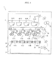
- FIG. 1 is a schematic diagram schematically showing an image forming apparatus according to an embodiment of the present disclosure.
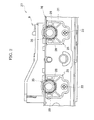
- FIG. 2 is an enlarged front view showing a schematic configuration of a unit structure according to the embodiment of the present disclosure.
- FIG. 3 is a perspective view showing a schematic configuration of a positioning boss and a positioning member of an LSU according to the embodiment of the present disclosure.
- FIG. 4 is a left top perspective view showing the schematic configuration of the positioning boss of the LSU according to the embodiment of the present disclosure.
- FIG. 5 is a right bottom perspective view showing the schematic configuration of the positioning boss of the LSU according to the embodiment of the present disclosure.
- FIG. 6 is a front view showing the schematic configuration of the positioning boss of the LSU according to the embodiment of the present disclosure.
- FIG. 7 is a front view showing the schematic configuration of a fixing member according to the embodiment of the present disclosure.
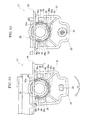
- FIG. 8A is a front view showing the LSU and fixing member before positioning and fixing in the embodiment of the present disclosure
- FIG. 8B is a front view showing the LSU and fixing member after positioning and fixing in the embodiment of the present disclosure.
- FIG. 9 is a front view showing a schematic configuration of a unit structure.
- FIG. 10 is an enlarged front view showing the schematic configuration of the unit structure.
- FIG. 11 is an enlarged back perspective view showing a fixing member before attaching to a frame.
- FIG. 12 is an enlarged horizontally sectional view showing the frame and an LSU after attaching to each other by the fixing member.
- FIG. 1 is a schematic diagram schematically showing the color printer according to an embodiment of the present disclosure.
- the reference characters "Y”, “C”, “M” and “K” appeared suitably in the specification and figure indicate colors of yellow, cyan, magenta and black.
- the color printer 1 includes a box-formed case 2.
- a sheet feeding cartridge 3 configured to store sheets for transferring (not shown) is installed and, in an upper part of the case 2, an ejected sheet tray 4 is formed.
- an intermediate transferring belt 5 as an image carrier is bridged over a pluralityof rollers.
- an exposure device 10 is installed below the intermediate transferring belt 5.
- the exposure device 10 consists of four laser scanning units (LSU) 9(Y), 9(C), 9(M) and 9(K) (hereinafter, collectively indicated by “LSU 9") arranged for respective colors of toners (developers).
- LSU 9 laser scanning units
- image forming unit 6 is installed for respective colors of toners.
- each image forming unit 6 a photosensitive drum 7 is rotatably attached.
- a charger 8 Around the photosensitive drum 7, a charger 8, a development device 11, a first transferring unit 12, a cleaning device 13 and a static eliminator 14 are located.
- a pair of stirring rollers 15 are installed, diagonally above of the stirring rollers 15, a magnetic roller 16 is installed and, diagonally above of the magnetic roller 16, a developing roller 17 is installed.
- a developing roller 17 is installed above the development device 11.
- four containers 18(Y), 18(C), 18(M) and 18(K) (hereinafter, collectively indicated by “container 18") as toner cases corresponding to the image forming units 6 are installed for respective colors of the toners.
- a sheet conveying path 20 of the sheet is arranged.
- a sheet feeder 21 is positioned.
- a second transferring unit 22 is positioned in contact with one end (a right end of the figure) of the intermediate transferring belt 5.
- a fixing unit 23 is positioned and, at a lower stream end of the conveying path 20, an ejection opening 24 is positioned.
- the surface of the photosensitive drum 7 is electrically charged by the charger 8. Then, exposure corresponding to the image data on the photosensitive drum 7 is carried out by a laser (refer to arrow P) from the exposure device 10, thereby forming an electrostatic latent image on the surface of the photosensitive drum 7.
- the electrostatic latent image is developed to a toner image having a correspondent color with the toner in the development device 11.
- the toner image is first-transferred onto the surface of the intermediate transferring belt 5 in the first transferring unit 12. The above-mentioned operation is repeated in order by the image forming units 6, thereby forming the toner image having full color onto the intermediate transferring belt 5. Toner and electric charge remained on the photosensitive drum 7 are eliminated by the cleaning device 13 and static eliminator 14.
- the sheet fed from the sheet feeding cartridge 3 or a manual bypass tray (not shown) by the sheet feeder 21 is conveyed to the second transferring unit 22 in a suitable timing for the above-mentioned image forming operation. Then, in the second transferring unit 22, the toner image having full color on the intermediate transferring belt 5 is second-transferred onto the sheet.
- the sheet with the second-transferred toner image is conveyed to a lower stream on the conveying path 20 to enter the fixing unit 23, and then, the toner image is fixed on the sheet in the fixing unit 23.
- the sheet with the fixed toner image is ejected from the ejection opening 24 onto the ejected sheet tray 4.
- the unit structure 27 configured to position and fix the above-mentioned LSUs 9 to the frame 26 as a supporting structure by fixing members 25 will be described.
- the unit structure 27 includes the four LSUs 9, frame 26 and fixing members 25.
- positioning bosses 28 are formed in the LSUs 9, positioning bosses 28 are formed in the frame 26, openings 29 holding the positioning bosses 28 are formed.
- the fixing members 25 respectively positions and fixes the LSUs 9 to the frame 26.
- the LSU 9 is formed in a longitudinal box-liked shape. As shown in FIG. 2 , in a front side (one side) of the LSU 9 in the longitudinal direction, a pair of positioning bosses 28 are formed side by side. The positioning bosses 28 are formed in a cylinder-liked shape. On the other hand, in a rear side (another side) of the LSU 9 in the longitudinal direction, other positioning bosses not shown are formed.
- groove-liked depressions 30 are formed to extend from a top edge of the positioning boss 28 backward.
- the depressions 30 are respectively arranged at three positions on the outer circumference face of each positioning boss 28.
- the depressions 30 are also located at equal intervals in a circumferential direction of each positioning boss 28.
- a bottom face 30a of the depression 30 slopes upward in a clockwise direction in a front view. That is, the depth of the depression 30 gradually shallows in the clockwise direction in the front view.
- the frame 26 is attached, as shown in FIG. 1 , inside the case 2.
- This frame 26 is configured, as shown in FIG. 2 , in a rectangular frame-liked shape in a planer view by a front side plate 31, a rear side plate, a right side plate and a left side plate (not shown).
- An upper end and a lower end of the front side plate 31 are bent forward (laterally).
- the openings 29 capable of insertion of the positioning bosses 28 are formed in shapes and a positions respectively corresponding to the positioning bosses 28.
- the opening 29 is formed by a cut-out over the bending part of the front side plate 31.
- An inside diameter of the opening 29 is determined greater than an outside diameter of the positioning boss 28.
- other openings (not shown) capable of insertion of the other positioning bosses in the rear side of the LSU 9 in the longitudinal direction is formed.
- the fixing member 25 is formed, as shown in FIGS. 3 and 7 , in a shape liked a plate which has a lower end cut out inward at both sides.
- a penetrating hole 34 capable of insertion of a screw 33 (refer to FIGS. 2 and 8B ) is bored, while, in an upper part of the fixing member 25, a cylinder-liked annular part 35 is formed.
- An upper part of the annular part 35 is configured to protrude from an upper end of the fixing member 25, and, in a lower part of the annular part 35, a half cylinder-liked back extending part 35a (refer to FIG. 3 ) extending backward is formed.
- An outer circumference face of the back extending part 35a is configured in the dimensions capable of fitting to an internal circumference face of the opening 29.
- an internal circumference face of the annular part 35 is configured in the dimensions capable of fitting to an outer circumference face of the positioning boss 28.
- projections 36 insertable in the depressions 30 of the positioning boss 28 are formed on the internal circumference face of the annular part 35 .
- the projections 36 are arranged at three positions on the internal circumference face of the annular part 35 corresponding to the depressions 30 and the projections 36 are located at equal intervals in a circumferential direction.
- a top face 36a of the projection 36 slopes downward in the same direction as the bottom face 30a of the depression 30 (the clockwise direction) in the front view. That is, the height of the projection 36 gradually lowers in the clockwise direction in the front view of the annular part 35.
- the annular part 35 is pushed further, and simultaneously, the fixing member 25 is turned in the clockwise direction in the front view (this turning direction is indicated by a reference character A). Accordingly, the outer circumference face of the back extending part 35a is fitted to the internal circumference face of the opening 29 and a gap between the top face 36a of the projection 36 and bottom face 30a of the depression 30 is closed. Thereby, the internal circumference face of the annular part 35 is fitted on the outer circumference face of the positioning boss 28. Thereafter, as shown in FIG. 8B , the screw 33 is inserted in the penetrating hole 34 and the screw 33 is screwed to a tapped hole 26a (refer to FIG. 8A ) of the frame 26. Thereby, the LSU 9 is positioned and fixed to the frame 26 by the fixing member 25.
- both the top face 36a of the projection 36 and bottom face 30a of the depression 30 slope in the same direction on the respective circumferences in the front view. Accordingly, even if accuracy of the dimensions of the annular part 35 and positioning boss 28 become uneven, by turning the fixing member in a direction of narrowing a gap between the top face of the projection and bottom face of the depression, the top face of the projection is fastened to the bottom face of the depression. It is therefore possible to fit the annular part and positioning boss to each other without any gap. Thereby, it is possible to fix the optical scanner to the supporting structure with great accuracy of the positioning.
- the projections 36 are arranged at three positions at equal intervals in the circumferential direction and, on the outer circumference face of the positioning boss 28, the depressions 30 are arranged, according to the projections 36, at three positions at equal intervals in the circumferential direction. Therefore, because the positioning boss 28 can be positioned and fixed over the entire circumference, it is possible to more increase the accuracy of the positioning of the LSU 9 to the frame 26.
- a pair of the positioning bosses 28 are arranged side by side and a pair of the fixing members 25 are respectively provided according to the positioning bosses 28. Therefore, because the positioning bosses 28 can be separately positioned, it is possible to furthermore increase the accuracy of the positioning of the LSU 9 to the frame 26.
- the above-mentioned embodiment was described about a case where the projections 36 are formed on the internal circumference face of the annular part 35 and the depressions 30 are formed on the outer circumference face of the positioning boss 28.
- the depressions 30 may be formed on the internal circumference face of the annular part 35 and the projections 36 may be formed on the outer circumference face of the positioning boss 28.
- any one of the top face 36a of the projection 36 and bottom face 30a of the depression 30 may slope to one side on the circumference in the front view.
- the above-mentioned embodiment was described about a case where the top face 36a of the projection 36 slopes downward in the clockwise direction in the front view and the bottom face 30a of the depression 30 slopes upward in the clockwise direction in the front view.
- the slope directions of the top face 36a of the projection 36 and bottom face 30a of the depression 30 may be the reverse of the above-mentioned case.
- the fixing member 25 may be turned in a counterclockwise direction in the front view. That is, the fixing member 25 may be turned in a direction of narrowing a gap between the top face 36a of the projection 36 and bottom face 30a of the depression30.
- each of the projection 36 and depression 30 may be formed at one position. That is, it is preferable to provide one or more pairs of the projection 36 and depression 30.
Landscapes
- Physics & Mathematics (AREA)
- General Physics & Mathematics (AREA)
- Electrophotography Configuration And Component (AREA)
- Exposure Or Original Feeding In Electrophotography (AREA)
- Mechanical Optical Scanning Systems (AREA)
Applications Claiming Priority (1)
| Application Number | Priority Date | Filing Date | Title |
|---|---|---|---|
| JP2012118484A JP5678003B2 (ja) | 2012-05-24 | 2012-05-24 | 光走査装置の取付構造 |
Publications (3)
| Publication Number | Publication Date |
|---|---|
| EP2667264A2 true EP2667264A2 (de) | 2013-11-27 |
| EP2667264A3 EP2667264A3 (de) | 2017-08-23 |
| EP2667264B1 EP2667264B1 (de) | 2018-04-25 |
Family
ID=48482940
Family Applications (1)
| Application Number | Title | Priority Date | Filing Date |
|---|---|---|---|
| EP13168550.5A Not-in-force EP2667264B1 (de) | 2012-05-24 | 2013-05-21 | Befestigungsmechanismus eines optischen Abtasters und Bilderzeugungsvorrichtung |
Country Status (4)
| Country | Link |
|---|---|
| US (1) | US8760484B2 (de) |
| EP (1) | EP2667264B1 (de) |
| JP (1) | JP5678003B2 (de) |
| CN (1) | CN103425012B (de) |
Families Citing this family (1)
| Publication number | Priority date | Publication date | Assignee | Title |
|---|---|---|---|---|
| USD743397S1 (en) * | 2014-06-20 | 2015-11-17 | Datalogic Ip Tech S.R.L. | Optical scanner |
Family Cites Families (10)
| Publication number | Priority date | Publication date | Assignee | Title |
|---|---|---|---|---|
| US3874752A (en) * | 1974-01-18 | 1975-04-01 | Yasutaka Imazaike | Synthetic resin-made bearing |
| JPH11194281A (ja) | 1997-12-26 | 1999-07-21 | Fuji Xerox Co Ltd | レーザ記録装置及びレーザ走査装置の取付方法 |
| JP3592526B2 (ja) | 1998-05-25 | 2004-11-24 | 株式会社リコー | フレーム構造及びこれを有する画像形成装置 |
| KR20080006391A (ko) * | 2006-07-12 | 2008-01-16 | 삼성전자주식회사 | 변형제한영역을 갖는 화상형성장치 |
| JP4498407B2 (ja) * | 2006-12-22 | 2010-07-07 | キヤノン株式会社 | プロセスカートリッジ、電子写真画像形成装置、及び、電子写真感光体ドラムユニット |
| JP5060889B2 (ja) | 2007-09-25 | 2012-10-31 | 株式会社リコー | 画像形成装置 |
| JP2010081755A (ja) * | 2008-09-26 | 2010-04-08 | Fuji Xerox Co Ltd | モーター取付構造及びこれを用いた画像形成装置 |
| JP2011209557A (ja) | 2010-03-30 | 2011-10-20 | Kyocera Mita Corp | 光走査装置の固定機構及び画像形成装置 |
| JP5111559B2 (ja) * | 2010-05-28 | 2013-01-09 | 京セラドキュメントソリューションズ株式会社 | 支持構造及び画像形成装置 |
| JP5397328B2 (ja) * | 2010-06-28 | 2014-01-22 | 株式会社リコー | 画像形成装置 |
-
2012
- 2012-05-24 JP JP2012118484A patent/JP5678003B2/ja not_active Expired - Fee Related
-
2013
- 2013-05-21 EP EP13168550.5A patent/EP2667264B1/de not_active Not-in-force
- 2013-05-21 US US13/899,390 patent/US8760484B2/en not_active Expired - Fee Related
- 2013-05-22 CN CN201310193065.8A patent/CN103425012B/zh not_active Expired - Fee Related
Non-Patent Citations (1)
| Title |
|---|
| None |
Also Published As
| Publication number | Publication date |
|---|---|
| US20130314485A1 (en) | 2013-11-28 |
| EP2667264B1 (de) | 2018-04-25 |
| US8760484B2 (en) | 2014-06-24 |
| CN103425012A (zh) | 2013-12-04 |
| CN103425012B (zh) | 2016-06-01 |
| JP5678003B2 (ja) | 2015-02-25 |
| EP2667264A3 (de) | 2017-08-23 |
| JP2013246238A (ja) | 2013-12-09 |
Similar Documents
| Publication | Publication Date | Title |
|---|---|---|
| JP5414171B2 (ja) | 画像形成装置 | |
| EP2146256B1 (de) | Bilderzeugungsvorrichtung | |
| EP2138908A1 (de) | In einer Bilderzeugungsvorrichtung herausnehmbar eingesetzte tandemartige Prozesseinheit | |
| CN108345203B (zh) | 显影装置、处理盒和成像设备 | |
| US10054898B2 (en) | Image forming apparatus | |
| US9494910B2 (en) | Image forming apparatus comprising board holding member configured to have surface to which board is fixed | |
| JP2008310120A (ja) | 画像形成装置 | |
| US20240369966A1 (en) | Image forming apparatus having improved mountability of a cartridge while conserving space | |
| JP5353936B2 (ja) | 画像形成装置 | |
| US20190094793A1 (en) | Image forming apparatus | |
| JP6615402B2 (ja) | カートリッジおよび画像形成装置 | |
| JP2009075442A (ja) | 画像形成装置 | |
| JP6029393B2 (ja) | プロセスカートリッジ | |
| US8760484B2 (en) | Attachment mechanism of optical scanner and image forming apparatus | |
| US10067463B2 (en) | Image forming apparatus | |
| JP5139818B2 (ja) | 現像装置及びこれを備えた画像形成装置 | |
| JP7210318B2 (ja) | プロセスカートリッジ及び画像形成装置 | |
| JP7218167B2 (ja) | 画像形成装置 | |
| JP2018049198A (ja) | 画像形成装置及び装置本体 | |
| US9342043B2 (en) | Unit assembly and image forming apparatus | |
| JP4730470B2 (ja) | 画像形成装置 | |
| JP5970621B2 (ja) | 画像形成装置 | |
| US20070065176A1 (en) | Developing unit and an image forming apparatus including the developing unit | |
| US20190354065A1 (en) | Developing device and image forming apparatus including the same | |
| JPH0635245A (ja) | プロセスユニット |
Legal Events
| Date | Code | Title | Description |
|---|---|---|---|
| PUAI | Public reference made under article 153(3) epc to a published international application that has entered the european phase |
Free format text: ORIGINAL CODE: 0009012 |
|
| AK | Designated contracting states |
Kind code of ref document: A2 Designated state(s): AL AT BE BG CH CY CZ DE DK EE ES FI FR GB GR HR HU IE IS IT LI LT LU LV MC MK MT NL NO PL PT RO RS SE SI SK SM TR |
|
| AX | Request for extension of the european patent |
Extension state: BA ME |
|
| PUAL | Search report despatched |
Free format text: ORIGINAL CODE: 0009013 |
|
| AK | Designated contracting states |
Kind code of ref document: A3 Designated state(s): AL AT BE BG CH CY CZ DE DK EE ES FI FR GB GR HR HU IE IS IT LI LT LU LV MC MK MT NL NO PL PT RO RS SE SI SK SM TR |
|
| AX | Request for extension of the european patent |
Extension state: BA ME |
|
| RIC1 | Information provided on ipc code assigned before grant |
Ipc: G03G 21/16 20060101AFI20170719BHEP |
|
| STAA | Information on the status of an ep patent application or granted ep patent |
Free format text: STATUS: REQUEST FOR EXAMINATION WAS MADE |
|
| 17P | Request for examination filed |
Effective date: 20171218 |
|
| RBV | Designated contracting states (corrected) |
Designated state(s): AL AT BE BG CH CY CZ DE DK EE ES FI FR GB GR HR HU IE IS IT LI LT LU LV MC MK MT NL NO PL PT RO RS SE SI SK SM TR |
|
| GRAP | Despatch of communication of intention to grant a patent |
Free format text: ORIGINAL CODE: EPIDOSNIGR1 |
|
| STAA | Information on the status of an ep patent application or granted ep patent |
Free format text: STATUS: GRANT OF PATENT IS INTENDED |
|
| INTG | Intention to grant announced |
Effective date: 20180213 |
|
| GRAA | (expected) grant |
Free format text: ORIGINAL CODE: 0009210 |
|
| GRAS | Grant fee paid |
Free format text: ORIGINAL CODE: EPIDOSNIGR3 |
|
| STAA | Information on the status of an ep patent application or granted ep patent |
Free format text: STATUS: THE PATENT HAS BEEN GRANTED |
|
| AK | Designated contracting states |
Kind code of ref document: B1 Designated state(s): AL AT BE BG CH CY CZ DE DK EE ES FI FR GB GR HR HU IE IS IT LI LT LU LV MC MK MT NL NO PL PT RO RS SE SI SK SM TR |
|
| REG | Reference to a national code |
Ref country code: GB Ref legal event code: FG4D |
|
| REG | Reference to a national code |
Ref country code: CH Ref legal event code: EP |
|
| REG | Reference to a national code |
Ref country code: AT Ref legal event code: REF Ref document number: 993543 Country of ref document: AT Kind code of ref document: T Effective date: 20180515 |
|
| REG | Reference to a national code |
Ref country code: IE Ref legal event code: FG4D |
|
| REG | Reference to a national code |
Ref country code: DE Ref legal event code: R096 Ref document number: 602013036352 Country of ref document: DE |
|
| REG | Reference to a national code |
Ref country code: FR Ref legal event code: PLFP Year of fee payment: 6 |
|
| REG | Reference to a national code |
Ref country code: NL Ref legal event code: MP Effective date: 20180425 |
|
| REG | Reference to a national code |
Ref country code: LT Ref legal event code: MG4D |
|
| PG25 | Lapsed in a contracting state [announced via postgrant information from national office to epo] |
Ref country code: NL Free format text: LAPSE BECAUSE OF FAILURE TO SUBMIT A TRANSLATION OF THE DESCRIPTION OR TO PAY THE FEE WITHIN THE PRESCRIBED TIME-LIMIT Effective date: 20180425 |
|
| PG25 | Lapsed in a contracting state [announced via postgrant information from national office to epo] |
Ref country code: SE Free format text: LAPSE BECAUSE OF FAILURE TO SUBMIT A TRANSLATION OF THE DESCRIPTION OR TO PAY THE FEE WITHIN THE PRESCRIBED TIME-LIMIT Effective date: 20180425 Ref country code: PL Free format text: LAPSE BECAUSE OF FAILURE TO SUBMIT A TRANSLATION OF THE DESCRIPTION OR TO PAY THE FEE WITHIN THE PRESCRIBED TIME-LIMIT Effective date: 20180425 Ref country code: LT Free format text: LAPSE BECAUSE OF FAILURE TO SUBMIT A TRANSLATION OF THE DESCRIPTION OR TO PAY THE FEE WITHIN THE PRESCRIBED TIME-LIMIT Effective date: 20180425 Ref country code: ES Free format text: LAPSE BECAUSE OF FAILURE TO SUBMIT A TRANSLATION OF THE DESCRIPTION OR TO PAY THE FEE WITHIN THE PRESCRIBED TIME-LIMIT Effective date: 20180425 Ref country code: BG Free format text: LAPSE BECAUSE OF FAILURE TO SUBMIT A TRANSLATION OF THE DESCRIPTION OR TO PAY THE FEE WITHIN THE PRESCRIBED TIME-LIMIT Effective date: 20180725 Ref country code: NO Free format text: LAPSE BECAUSE OF FAILURE TO SUBMIT A TRANSLATION OF THE DESCRIPTION OR TO PAY THE FEE WITHIN THE PRESCRIBED TIME-LIMIT Effective date: 20180725 Ref country code: FI Free format text: LAPSE BECAUSE OF FAILURE TO SUBMIT A TRANSLATION OF THE DESCRIPTION OR TO PAY THE FEE WITHIN THE PRESCRIBED TIME-LIMIT Effective date: 20180425 |
|
| PG25 | Lapsed in a contracting state [announced via postgrant information from national office to epo] |
Ref country code: GR Free format text: LAPSE BECAUSE OF FAILURE TO SUBMIT A TRANSLATION OF THE DESCRIPTION OR TO PAY THE FEE WITHIN THE PRESCRIBED TIME-LIMIT Effective date: 20180726 Ref country code: LV Free format text: LAPSE BECAUSE OF FAILURE TO SUBMIT A TRANSLATION OF THE DESCRIPTION OR TO PAY THE FEE WITHIN THE PRESCRIBED TIME-LIMIT Effective date: 20180425 Ref country code: RS Free format text: LAPSE BECAUSE OF FAILURE TO SUBMIT A TRANSLATION OF THE DESCRIPTION OR TO PAY THE FEE WITHIN THE PRESCRIBED TIME-LIMIT Effective date: 20180425 Ref country code: HR Free format text: LAPSE BECAUSE OF FAILURE TO SUBMIT A TRANSLATION OF THE DESCRIPTION OR TO PAY THE FEE WITHIN THE PRESCRIBED TIME-LIMIT Effective date: 20180425 |
|
| REG | Reference to a national code |
Ref country code: CH Ref legal event code: PL |
|
| REG | Reference to a national code |
Ref country code: AT Ref legal event code: MK05 Ref document number: 993543 Country of ref document: AT Kind code of ref document: T Effective date: 20180425 |
|
| PG25 | Lapsed in a contracting state [announced via postgrant information from national office to epo] |
Ref country code: PT Free format text: LAPSE BECAUSE OF FAILURE TO SUBMIT A TRANSLATION OF THE DESCRIPTION OR TO PAY THE FEE WITHIN THE PRESCRIBED TIME-LIMIT Effective date: 20180827 |
|
| REG | Reference to a national code |
Ref country code: DE Ref legal event code: R097 Ref document number: 602013036352 Country of ref document: DE |
|
| REG | Reference to a national code |
Ref country code: BE Ref legal event code: MM Effective date: 20180531 |
|
| PG25 | Lapsed in a contracting state [announced via postgrant information from national office to epo] |
Ref country code: SK Free format text: LAPSE BECAUSE OF FAILURE TO SUBMIT A TRANSLATION OF THE DESCRIPTION OR TO PAY THE FEE WITHIN THE PRESCRIBED TIME-LIMIT Effective date: 20180425 Ref country code: MC Free format text: LAPSE BECAUSE OF FAILURE TO SUBMIT A TRANSLATION OF THE DESCRIPTION OR TO PAY THE FEE WITHIN THE PRESCRIBED TIME-LIMIT Effective date: 20180425 Ref country code: AT Free format text: LAPSE BECAUSE OF FAILURE TO SUBMIT A TRANSLATION OF THE DESCRIPTION OR TO PAY THE FEE WITHIN THE PRESCRIBED TIME-LIMIT Effective date: 20180425 Ref country code: DK Free format text: LAPSE BECAUSE OF FAILURE TO SUBMIT A TRANSLATION OF THE DESCRIPTION OR TO PAY THE FEE WITHIN THE PRESCRIBED TIME-LIMIT Effective date: 20180425 Ref country code: CZ Free format text: LAPSE BECAUSE OF FAILURE TO SUBMIT A TRANSLATION OF THE DESCRIPTION OR TO PAY THE FEE WITHIN THE PRESCRIBED TIME-LIMIT Effective date: 20180425 Ref country code: RO Free format text: LAPSE BECAUSE OF FAILURE TO SUBMIT A TRANSLATION OF THE DESCRIPTION OR TO PAY THE FEE WITHIN THE PRESCRIBED TIME-LIMIT Effective date: 20180425 Ref country code: EE Free format text: LAPSE BECAUSE OF FAILURE TO SUBMIT A TRANSLATION OF THE DESCRIPTION OR TO PAY THE FEE WITHIN THE PRESCRIBED TIME-LIMIT Effective date: 20180425 |
|
| REG | Reference to a national code |
Ref country code: IE Ref legal event code: MM4A |
|
| PG25 | Lapsed in a contracting state [announced via postgrant information from national office to epo] |
Ref country code: LI Free format text: LAPSE BECAUSE OF NON-PAYMENT OF DUE FEES Effective date: 20180531 Ref country code: SM Free format text: LAPSE BECAUSE OF FAILURE TO SUBMIT A TRANSLATION OF THE DESCRIPTION OR TO PAY THE FEE WITHIN THE PRESCRIBED TIME-LIMIT Effective date: 20180425 Ref country code: CH Free format text: LAPSE BECAUSE OF NON-PAYMENT OF DUE FEES Effective date: 20180531 Ref country code: IT Free format text: LAPSE BECAUSE OF FAILURE TO SUBMIT A TRANSLATION OF THE DESCRIPTION OR TO PAY THE FEE WITHIN THE PRESCRIBED TIME-LIMIT Effective date: 20180425 |
|
| PLBE | No opposition filed within time limit |
Free format text: ORIGINAL CODE: 0009261 |
|
| STAA | Information on the status of an ep patent application or granted ep patent |
Free format text: STATUS: NO OPPOSITION FILED WITHIN TIME LIMIT |
|
| PG25 | Lapsed in a contracting state [announced via postgrant information from national office to epo] |
Ref country code: LU Free format text: LAPSE BECAUSE OF NON-PAYMENT OF DUE FEES Effective date: 20180521 |
|
| 26N | No opposition filed |
Effective date: 20190128 |
|
| PG25 | Lapsed in a contracting state [announced via postgrant information from national office to epo] |
Ref country code: IE Free format text: LAPSE BECAUSE OF NON-PAYMENT OF DUE FEES Effective date: 20180521 |
|
| PG25 | Lapsed in a contracting state [announced via postgrant information from national office to epo] |
Ref country code: BE Free format text: LAPSE BECAUSE OF NON-PAYMENT OF DUE FEES Effective date: 20180531 Ref country code: SI Free format text: LAPSE BECAUSE OF FAILURE TO SUBMIT A TRANSLATION OF THE DESCRIPTION OR TO PAY THE FEE WITHIN THE PRESCRIBED TIME-LIMIT Effective date: 20180425 |
|
| PG25 | Lapsed in a contracting state [announced via postgrant information from national office to epo] |
Ref country code: AL Free format text: LAPSE BECAUSE OF FAILURE TO SUBMIT A TRANSLATION OF THE DESCRIPTION OR TO PAY THE FEE WITHIN THE PRESCRIBED TIME-LIMIT Effective date: 20180425 |
|
| PG25 | Lapsed in a contracting state [announced via postgrant information from national office to epo] |
Ref country code: MT Free format text: LAPSE BECAUSE OF NON-PAYMENT OF DUE FEES Effective date: 20180521 |
|
| PG25 | Lapsed in a contracting state [announced via postgrant information from national office to epo] |
Ref country code: TR Free format text: LAPSE BECAUSE OF FAILURE TO SUBMIT A TRANSLATION OF THE DESCRIPTION OR TO PAY THE FEE WITHIN THE PRESCRIBED TIME-LIMIT Effective date: 20180425 |
|
| PG25 | Lapsed in a contracting state [announced via postgrant information from national office to epo] |
Ref country code: HU Free format text: LAPSE BECAUSE OF FAILURE TO SUBMIT A TRANSLATION OF THE DESCRIPTION OR TO PAY THE FEE WITHIN THE PRESCRIBED TIME-LIMIT; INVALID AB INITIO Effective date: 20130521 |
|
| PG25 | Lapsed in a contracting state [announced via postgrant information from national office to epo] |
Ref country code: CY Free format text: LAPSE BECAUSE OF FAILURE TO SUBMIT A TRANSLATION OF THE DESCRIPTION OR TO PAY THE FEE WITHIN THE PRESCRIBED TIME-LIMIT Effective date: 20180425 Ref country code: MK Free format text: LAPSE BECAUSE OF NON-PAYMENT OF DUE FEES Effective date: 20180425 |
|
| PG25 | Lapsed in a contracting state [announced via postgrant information from national office to epo] |
Ref country code: IS Free format text: LAPSE BECAUSE OF FAILURE TO SUBMIT A TRANSLATION OF THE DESCRIPTION OR TO PAY THE FEE WITHIN THE PRESCRIBED TIME-LIMIT Effective date: 20180825 |
|
| P01 | Opt-out of the competence of the unified patent court (upc) registered |
Effective date: 20230420 |
|
| PGFP | Annual fee paid to national office [announced via postgrant information from national office to epo] |
Ref country code: FR Payment date: 20230420 Year of fee payment: 11 Ref country code: DE Payment date: 20230419 Year of fee payment: 11 |
|
| PGFP | Annual fee paid to national office [announced via postgrant information from national office to epo] |
Ref country code: GB Payment date: 20230420 Year of fee payment: 11 |
|
| REG | Reference to a national code |
Ref country code: DE Ref legal event code: R119 Ref document number: 602013036352 Country of ref document: DE |
|
| GBPC | Gb: european patent ceased through non-payment of renewal fee |
Effective date: 20240521 |
|
| PG25 | Lapsed in a contracting state [announced via postgrant information from national office to epo] |
Ref country code: DE Free format text: LAPSE BECAUSE OF NON-PAYMENT OF DUE FEES Effective date: 20241203 |
|
| PG25 | Lapsed in a contracting state [announced via postgrant information from national office to epo] |
Ref country code: FR Free format text: LAPSE BECAUSE OF NON-PAYMENT OF DUE FEES Effective date: 20240531 |
|
| PG25 | Lapsed in a contracting state [announced via postgrant information from national office to epo] |
Ref country code: GB Free format text: LAPSE BECAUSE OF NON-PAYMENT OF DUE FEES Effective date: 20240521 |