EP2666452B1 - Stationswagen, insbesondere Visiten- und Pflegewagen - Google Patents
Stationswagen, insbesondere Visiten- und Pflegewagen Download PDFInfo
- Publication number
- EP2666452B1 EP2666452B1 EP13167806.2A EP13167806A EP2666452B1 EP 2666452 B1 EP2666452 B1 EP 2666452B1 EP 13167806 A EP13167806 A EP 13167806A EP 2666452 B1 EP2666452 B1 EP 2666452B1
- Authority
- EP
- European Patent Office
- Prior art keywords
- cable
- trolley
- space
- monitor
- storage space
- Prior art date
- Legal status (The legal status is an assumption and is not a legal conclusion. Google has not performed a legal analysis and makes no representation as to the accuracy of the status listed.)
- Active
Links
Images




Classifications
-
- A—HUMAN NECESSITIES
- A61—MEDICAL OR VETERINARY SCIENCE; HYGIENE
- A61G—TRANSPORT, PERSONAL CONVEYANCES, OR ACCOMMODATION SPECIALLY ADAPTED FOR PATIENTS OR DISABLED PERSONS; OPERATING TABLES OR CHAIRS; CHAIRS FOR DENTISTRY; FUNERAL DEVICES
- A61G12/00—Accommodation for nursing, e.g. in hospitals, not covered by groups A61G1/00 - A61G11/00, e.g. trolleys for transport of medicaments or food; Prescription lists
- A61G12/001—Trolleys for transport of medicaments, food, linen, nursing supplies
-
- A—HUMAN NECESSITIES
- A61—MEDICAL OR VETERINARY SCIENCE; HYGIENE
- A61B—DIAGNOSIS; SURGERY; IDENTIFICATION
- A61B50/00—Containers, covers, furniture or holders specially adapted for surgical or diagnostic appliances or instruments, e.g. sterile covers
- A61B50/10—Furniture specially adapted for surgical or diagnostic appliances or instruments
- A61B50/13—Trolleys, e.g. carts
-
- A—HUMAN NECESSITIES
- A61—MEDICAL OR VETERINARY SCIENCE; HYGIENE
- A61B—DIAGNOSIS; SURGERY; IDENTIFICATION
- A61B50/00—Containers, covers, furniture or holders specially adapted for surgical or diagnostic appliances or instruments, e.g. sterile covers
- A61B50/10—Furniture specially adapted for surgical or diagnostic appliances or instruments
- A61B50/15—Mayo stands; Tables
-
- A—HUMAN NECESSITIES
- A61—MEDICAL OR VETERINARY SCIENCE; HYGIENE
- A61B—DIAGNOSIS; SURGERY; IDENTIFICATION
- A61B50/00—Containers, covers, furniture or holders specially adapted for surgical or diagnostic appliances or instruments, e.g. sterile covers
- A61B50/10—Furniture specially adapted for surgical or diagnostic appliances or instruments
- A61B50/18—Cupboards; Drawers therefor
-
- A—HUMAN NECESSITIES
- A61—MEDICAL OR VETERINARY SCIENCE; HYGIENE
- A61B—DIAGNOSIS; SURGERY; IDENTIFICATION
- A61B50/00—Containers, covers, furniture or holders specially adapted for surgical or diagnostic appliances or instruments, e.g. sterile covers
- A61B50/30—Containers specially adapted for packaging, protecting, dispensing, collecting or disposing of surgical or diagnostic appliances or instruments
- A61B50/34—Baskets
-
- F—MECHANICAL ENGINEERING; LIGHTING; HEATING; WEAPONS; BLASTING
- F16—ENGINEERING ELEMENTS AND UNITS; GENERAL MEASURES FOR PRODUCING AND MAINTAINING EFFECTIVE FUNCTIONING OF MACHINES OR INSTALLATIONS; THERMAL INSULATION IN GENERAL
- F16M—FRAMES, CASINGS OR BEDS OF ENGINES, MACHINES OR APPARATUS, NOT SPECIFIC TO ENGINES, MACHINES OR APPARATUS PROVIDED FOR ELSEWHERE; STANDS; SUPPORTS
- F16M11/00—Stands or trestles as supports for apparatus or articles placed thereon ; Stands for scientific apparatus such as gravitational force meters
- F16M11/02—Heads
- F16M11/04—Means for attachment of apparatus; Means allowing adjustment of the apparatus relatively to the stand
- F16M11/06—Means for attachment of apparatus; Means allowing adjustment of the apparatus relatively to the stand allowing pivoting
- F16M11/10—Means for attachment of apparatus; Means allowing adjustment of the apparatus relatively to the stand allowing pivoting around a horizontal axis
-
- F—MECHANICAL ENGINEERING; LIGHTING; HEATING; WEAPONS; BLASTING
- F16—ENGINEERING ELEMENTS AND UNITS; GENERAL MEASURES FOR PRODUCING AND MAINTAINING EFFECTIVE FUNCTIONING OF MACHINES OR INSTALLATIONS; THERMAL INSULATION IN GENERAL
- F16M—FRAMES, CASINGS OR BEDS OF ENGINES, MACHINES OR APPARATUS, NOT SPECIFIC TO ENGINES, MACHINES OR APPARATUS PROVIDED FOR ELSEWHERE; STANDS; SUPPORTS
- F16M11/00—Stands or trestles as supports for apparatus or articles placed thereon ; Stands for scientific apparatus such as gravitational force meters
- F16M11/20—Undercarriages with or without wheels
- F16M11/2007—Undercarriages with or without wheels comprising means allowing pivoting adjustment
- F16M11/2014—Undercarriages with or without wheels comprising means allowing pivoting adjustment around a vertical axis
-
- F—MECHANICAL ENGINEERING; LIGHTING; HEATING; WEAPONS; BLASTING
- F16—ENGINEERING ELEMENTS AND UNITS; GENERAL MEASURES FOR PRODUCING AND MAINTAINING EFFECTIVE FUNCTIONING OF MACHINES OR INSTALLATIONS; THERMAL INSULATION IN GENERAL
- F16M—FRAMES, CASINGS OR BEDS OF ENGINES, MACHINES OR APPARATUS, NOT SPECIFIC TO ENGINES, MACHINES OR APPARATUS PROVIDED FOR ELSEWHERE; STANDS; SUPPORTS
- F16M11/00—Stands or trestles as supports for apparatus or articles placed thereon ; Stands for scientific apparatus such as gravitational force meters
- F16M11/20—Undercarriages with or without wheels
- F16M11/24—Undercarriages with or without wheels changeable in height or length of legs, also for transport only, e.g. by means of tubes screwed into each other
-
- F—MECHANICAL ENGINEERING; LIGHTING; HEATING; WEAPONS; BLASTING
- F16—ENGINEERING ELEMENTS AND UNITS; GENERAL MEASURES FOR PRODUCING AND MAINTAINING EFFECTIVE FUNCTIONING OF MACHINES OR INSTALLATIONS; THERMAL INSULATION IN GENERAL
- F16M—FRAMES, CASINGS OR BEDS OF ENGINES, MACHINES OR APPARATUS, NOT SPECIFIC TO ENGINES, MACHINES OR APPARATUS PROVIDED FOR ELSEWHERE; STANDS; SUPPORTS
- F16M11/00—Stands or trestles as supports for apparatus or articles placed thereon ; Stands for scientific apparatus such as gravitational force meters
- F16M11/42—Stands or trestles as supports for apparatus or articles placed thereon ; Stands for scientific apparatus such as gravitational force meters with arrangement for propelling the support stands on wheels
-
- A—HUMAN NECESSITIES
- A47—FURNITURE; DOMESTIC ARTICLES OR APPLIANCES; COFFEE MILLS; SPICE MILLS; SUCTION CLEANERS IN GENERAL
- A47B—TABLES; DESKS; OFFICE FURNITURE; CABINETS; DRAWERS; GENERAL DETAILS OF FURNITURE
- A47B31/00—Service or tea tables, trolleys, or wagons
- A47B2031/003—Service or tea tables, trolleys, or wagons with drawers, trays or shelves
-
- A—HUMAN NECESSITIES
- A47—FURNITURE; DOMESTIC ARTICLES OR APPLIANCES; COFFEE MILLS; SPICE MILLS; SUCTION CLEANERS IN GENERAL
- A47B—TABLES; DESKS; OFFICE FURNITURE; CABINETS; DRAWERS; GENERAL DETAILS OF FURNITURE
- A47B31/00—Service or tea tables, trolleys, or wagons
- A47B2031/006—Medication carts
-
- A—HUMAN NECESSITIES
- A61—MEDICAL OR VETERINARY SCIENCE; HYGIENE
- A61B—DIAGNOSIS; SURGERY; IDENTIFICATION
- A61B50/00—Containers, covers, furniture or holders specially adapted for surgical or diagnostic appliances or instruments, e.g. sterile covers
- A61B50/10—Furniture specially adapted for surgical or diagnostic appliances or instruments
- A61B2050/105—Cabinets
-
- A—HUMAN NECESSITIES
- A61—MEDICAL OR VETERINARY SCIENCE; HYGIENE
- A61B—DIAGNOSIS; SURGERY; IDENTIFICATION
- A61B50/00—Containers, covers, furniture or holders specially adapted for surgical or diagnostic appliances or instruments, e.g. sterile covers
- A61B50/10—Furniture specially adapted for surgical or diagnostic appliances or instruments
- A61B50/18—Cupboards; Drawers therefor
- A61B2050/185—Drawers
-
- A—HUMAN NECESSITIES
- A61—MEDICAL OR VETERINARY SCIENCE; HYGIENE
- A61B—DIAGNOSIS; SURGERY; IDENTIFICATION
- A61B50/00—Containers, covers, furniture or holders specially adapted for surgical or diagnostic appliances or instruments, e.g. sterile covers
- A61B50/30—Containers specially adapted for packaging, protecting, dispensing, collecting or disposing of surgical or diagnostic appliances or instruments
- A61B50/33—Trays
-
- A—HUMAN NECESSITIES
- A61—MEDICAL OR VETERINARY SCIENCE; HYGIENE
- A61G—TRANSPORT, PERSONAL CONVEYANCES, OR ACCOMMODATION SPECIALLY ADAPTED FOR PATIENTS OR DISABLED PERSONS; OPERATING TABLES OR CHAIRS; CHAIRS FOR DENTISTRY; FUNERAL DEVICES
- A61G12/00—Accommodation for nursing, e.g. in hospitals, not covered by groups A61G1/00 - A61G11/00, e.g. trolleys for transport of medicaments or food; Prescription lists
- A61G12/002—Supply appliances, e.g. columns for gas, fluid, electricity supply
- A61G12/008—Supply appliances, e.g. columns for gas, fluid, electricity supply mounted on a mobile base, e.g. on a trolley
-
- F—MECHANICAL ENGINEERING; LIGHTING; HEATING; WEAPONS; BLASTING
- F16—ENGINEERING ELEMENTS AND UNITS; GENERAL MEASURES FOR PRODUCING AND MAINTAINING EFFECTIVE FUNCTIONING OF MACHINES OR INSTALLATIONS; THERMAL INSULATION IN GENERAL
- F16M—FRAMES, CASINGS OR BEDS OF ENGINES, MACHINES OR APPARATUS, NOT SPECIFIC TO ENGINES, MACHINES OR APPARATUS PROVIDED FOR ELSEWHERE; STANDS; SUPPORTS
- F16M2200/00—Details of stands or supports
- F16M2200/06—Arms
- F16M2200/065—Arms with a special structure, e.g. reinforced or adapted for space reduction
Definitions
- a station wagon of the aforementioned, ie generic type is known from the prior art per se.
- Such a station cart discloses the US 2005/0001395 A1 , It is the peculiarity of the prior station car is that he has adjustable and variable in position partitions that allow to customize a placement of the station wagon with utensils patient-related.
- Further station wagons are for example from the DE 297 14 981 , of the DE 20 2005 013 115 , of the DE 20 2005 013 114 , of the DE 20 2008 015 373 as well as the DE 20 2011 051 973 known.
- a cover On the upper side of the cabinet part is usually provided a cover that is used in everyday practice, for example, as a writing pad and / or the inclusion of patient documents.
- station wagon which are equipped with a computer system and for this purpose have arranged on the station wagon monitor.
- a station wagon is for example from the DE 20 2011 051 973 known.
- a station wagon of the type mentioned above is proposed with the invention is characterized by a valve disposed on the cabinet part and accessible from the outside energy management system, the energy management system configured encapsulated and bottom sides of a bottom plate of the enclosure part is arranged, and through a pivotable on the enclosure part arranged monitor, wherein the monitor is supported by a tube which protrudes with its remote end into the cable space, wherein the monitor is arranged with interposition of a joint on the pipe, wherein the joint is covered by a spout.
- the cabinet part according to the station trolley according to the invention has a storage space in a conventional manner. This serves to accommodate utensils.
- a cable space is provided, which is provided by the cabinet part.
- the volume space provided by the cabinet part is accordingly formed from a storage space on the one hand and a cable space on the other hand.
- the cable space is formed lying in the loading direction of the cabinet part behind the storage space.
- the storage space and the cable space are separated by an intermediate wall, so that a front-side access to the cable space on the user side is not possible.
- the partition can also be referred to as a partition, which serves to shield the cable space from front access by a user.
- the storage space provides a storage compartment.
- This storage compartment has access to the cable compartment. There is therefore an accessibility or direct access to the cable compartment via the storage compartment provided by the storage compartment.
- the above-described embodiment makes it possible to record a computer system in an optimized manner, which may also permanently housed disturbing wiring permanently, which in particular simplifies handling.
- the development of the encapsulated version of the monitor and the concealed cable routing takes into account the increased hygiene and cleaning requirements demanded by the hospital.
- any failures, damage and / or the like By cable breakage and / or loosening cables are largely excluded because the cable space constructively ensures a proper and protected from external influences arrangement and storage of the cables of the computer system.
- the storage compartment provided by the storage space serves to accommodate the computer of the computer system. It is preferably provided in this context that the storage compartment at the front, i. Access side equipped by means of a storage door. This can be lockable equipped by means of a lock, so that an unwanted access to the computer recorded by the storage compartment is prevented.
- the cabinet part swivels a monitor. This one is in itself known manner connected via a cable connection to the computer arranged in the storage compartment.
- cable management is used in the loading direction of the cabinet part behind the storage space cable space.
- an access from the storage compartment to the cable compartment is provided according to the invention. This access may be an opening or a breakthrough in the intermediate space separating the storage space from the cable space.
- the monitor is preferably carried by a tube formed of aluminum or aluminum alloy.
- the monitor remote end of the tube protrudes into the cable space. This allows the cable routed from the computer into the cable compartment to be inaccessible from outside through the tube carrying the monitor to the connection sockets of the monitor.
- the power supply cable to be provided for the monitor can also be routed via the tube carrying the monitor into the cable space.
- the transition region between the monitor on the one hand and the tube on the other hand can be covered by a preferably made of plastic spout or sleeve.
- a likewise covered by the spout or the cuff joint is provided for the arrangement of the monitor on the pipe, so that the monitor can be selectively aligned in its inclination to the pipe.
- the monitor is height-adjustable arranged on the cabinet part of the station wagon.
- This height adjustment can for example be realized that the monitor carrying the tube is held vertically adjustable by a guide of the cabinet part.
- a height adjustment of the monitor can thus be effected by a corresponding height adjustment of the tube. It is provided in an advantageous manner to provide the height-adjustable recording of the tube within the cable space, which is not only the cables of the computer system, but also the monitor height adjustment of the cable compartment safely and protected against external influences added.
- the station wagon proposed by the invention may be referred to as encapsulated in its entirety.
- the monitor height adjustment and the cable guide are housed in a separately formed and separated from the storage compartment of the cabinet part cable space. External access is not without Further possible, and also an impairment in everyday practical use by exposed cables is avoided.
- the cabinet part has a removable rear wall.
- This rear wall can be removed on the user side both in the case of, for example, a first-time installation and / or in the case of a repair and / or retrofit, whereby access to the cable space and thus to the cabling accommodated therefrom is possible.
- the rear wall can be made lockable, so that a manipulative access is prevented by unauthorized persons.
- a 230V IEC plug is integrated in the rear wall. This is used to connect a power supply cable and / or a charger.
- the IEC connector is in turn connected to the computer system and / or an energy management system, so that a power supply is made possible via this central connection.
- the switch-on as well as any control functions are carried out on the user side via the monitor arranged on the cabinet part, so that in the intended use, a user-side access to the computer recorded by the storage compartment is not required.
- the cabinet part provides a drawer preferably designed extendable, the recording of peripheral devices such. a keyboard and / or mouse. In this case, such peripherals can be coupled via radio communication with the computer.
- a wiring may be provided, in which case the cables are routed through the monitor supporting the tube and the cable compartment to the computer.
- the station wagon has an energy management system equipped with batteries.
- the energy management system can be housed in the cable room.
- a housing accommodating the energy management system is provided, which is arranged on the underside of the base plate of the cabinet part.
- About appropriate breakthroughs in the bottom plate is a cable-protected connection of the energy management system to the arranged in the storage compartment of the station car calculator.
- a station wagon is provided in total, which allows it thanks to its structural design to accommodate a computer system including any existing peripherals in such a way that a fully enclosed arrangement is achieved and in particular otherwise disturbing cables are housed completely protected.
- the handling of the station wagon is thus improved overall and it can be completely avoided by otherwise exposed cable damage.
- unauthorized access to the computer system is avoided, which improves the security against manipulation.
- the development of the encapsulated version of the monitor and the concealed cable routing takes into account the increased hygiene and cleaning requirements demanded by the hospital.
- Fig. 1 can be seen in a plan view from the front station car according to the invention 1 according to a first embodiment.
- the station cart 1 has a cupboard part 2.
- This cupboard part 2 has on its underside a bottom plate 3 and top side a cover 6.
- the bottom plate 3 is supported by four support rollers 4, which are preferably designed to be rotatable about its vertical axis.
- the station cart 1 is designed to be movable.
- the cabinet part 2 provides a storage space 19 ready. This is used to hold utensils, wherein for an orderly accommodation baskets 10 may be provided, as the embodiment according to Fig. 1 can be identified by way of example.
- the cabinet part 2 has the front side via a door 7, which has two door leaves 8 and 9 in the illustrated embodiment, each providing a handle 15 in the form of a handle.
- the representation after Fig. 1 shows the door 7 and the door leaves 8 and 9 in an unassembled state, which allows the front view of the storage space 19.
- the others Figures 2 and 3 show the door 7 in its properly mounted and locked position.
- side view Fig. 2 can be provided to support the cover 6 with respect to the bottom part 3 posts 21 may be provided. These may be formed integrated in the side wall 5, or the side wall 5 extends from one post 21 to the next.
- the storage space 19 also provides a separately designed storage compartment 12 ready. This is the front side by means of a storage door 13 formed closable. In order to prevent access to the storage compartment by unauthorized persons, corresponding locking mechanisms for locking the storage door can be provided, for example in the configuration of a profile cylinder lock.
- the station cart 1 further provides a monitor 17. This is preferably pivotally and / or rotatably supported by a tube 18.
- a corresponding joint may be provided, according to the embodiment shown Fig. 2 wrapped by a spout 20 or cuff and covered with it.
- the spout 20 or sleeve is preferably made of plastic, whereas the tube 18 is preferably formed of aluminum or an aluminum alloy.
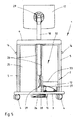
- the cabinet part 2 has a cable space 32. This is formed lying in the feed direction 31 of the cabinet part 2 behind the storage space 19, as in particular the rear view of the station cart 1 after Fig. 4 lets recognize.
- the storage space 19 and the cable space 32 are separated from each other by an intermediate wall 25. Due to this, front-side access to the cable space 32 through the storage space 19 is not possible.
- the storage compartment 12 provided by the storage compartment 19 provides access to the cable compartment 32, as shown in the illustration Fig. 5 results, after which the access is formed by an opening 33 in the intermediate wall 25.
- the storage compartment provided by the storage space 19 serves to receive a computer 27.
- the latter is coupled to the monitor 17 via a wiring 29.
- the wiring 29 is guided through the opening 33 in the inventively provided cable space 32 and from there through the pipe 18 to the terminals of the monitor 17. It shows Fig. 5 the better representation because not from the Figures 3 and 4 recognizable spout 20 or Cuff, which serves on the one hand, the cover of the monitor 17 to the pipe 18 connecting joint, but also the cover of the monitor-side cable connections.
- the tube 18 protrudes with its monitorentfernten end into the cable space 32, so in the final assembled state of the station cart 1 user side neither accessible nor visible. It is held by guide webs 26 or walls, which also allow a height adjustment of the tube 18 and thus of the monitor 17 relative to the cabinet part 2.
- the cabinet part 2 and thus the cable space 32 is closed at the rear by means of a rear wall 22, as shown in the illustration Fig. 4 lets recognize.
- the rear wall 22 integrally provides a plug 23 which serves as a central plug for the recorded from the station cart 1 computer system and is provided for connection to a power supply and / or a charger.
- the station cart 1 further has an energy management system 24, which is accommodated in the exemplary embodiment shown by a housing 16, which is arranged on the underside of the bottom plate 3 on the cabinet part 2.
- the energy management system 24 may have for the purpose of powering the computer system via replaceable batteries, so that an operation of the computer system without the direct connection to a power supply is permitted.
- the energy management system 24 is connected via a wiring 28 to the computer system, wherein the wiring 28 is guided by not shown in the figures openings in the bottom plate 3 in the cable space 32.
- the station cart 1 For receiving a keyboard, a mouse and / or the like.
- Peripheral devices the station cart 1 have a front accessible drawer 11, as can be seen for example from the illustration Fig. 1 or 3 results.
- Such peripheral devices may be in communication with the computer 27 via radio. It is also conceivable, however, a cable-based connection, in which case the cables of the peripheral devices are guided through a corresponding opening in the pipe 18 in selbiges and laid in the cable space 32.
- FIGS. 6 to 9 show a second embodiment of the invention, wherein the station cart 1 shown here instead of one accessible via a door 7 storage space 19 shows a fitted with drawers 30 storage space 19. Otherwise, the station cart 1 provides in the manner already described an encapsulated construction, according to a fully covered cable management is achieved with respect to the computer system.
Landscapes
- Health & Medical Sciences (AREA)
- Engineering & Computer Science (AREA)
- Life Sciences & Earth Sciences (AREA)
- General Engineering & Computer Science (AREA)
- Surgery (AREA)
- Biomedical Technology (AREA)
- Animal Behavior & Ethology (AREA)
- General Health & Medical Sciences (AREA)
- Public Health (AREA)
- Veterinary Medicine (AREA)
- Nuclear Medicine, Radiotherapy & Molecular Imaging (AREA)
- Mechanical Engineering (AREA)
- Heart & Thoracic Surgery (AREA)
- Medical Informatics (AREA)
- Molecular Biology (AREA)
- Nursing (AREA)
- Accommodation For Nursing Or Treatment Tables (AREA)
- Handcart (AREA)
Description
- Die Erfindung betrifft einen Stationswagen, insbesondere einen Visiten- und Pflegewagen für Krankenhäuser, Pflegeheime und sonstige Einrichtungen des Gesundheitswesens, mit einem fahrbar ausgebildeten Schrankteil, wobei das Schrankteil einen frontseitig zugänglichen Stauraum zur Aufnahme von Utensilien und einen in Beschickungsrichtung des Stauraums dahinterliegenden und vom Stauraum durch eine Zwischenwand getrennten Kabelraum aufweist, wobei der Stauraum ein Staufach bereitstellt, das einen Zugang zum Kabelraum aufweist.
- Ein Stationswagen der eingangs genannten, d.h. gattungsgemäßen Art ist aus dem Stand der Technik an sich bekannt. Einen solchen Stationswagen offenbart beispielsweise die
US 2005/0001395 A1 . Dabei besteht die Besonderheit des vorbekannten Stationswagens darin, dass er über verstellbare und in ihrer Position veränderliche Trennwände verfügt, die es gestatten, eine Bestückung des Stationswagens mit Utensilien patientenbezogen zu individualisieren. - Weitere Stationswagen sind beispielsweise aus der
DE 297 14 981 , derDE 20 2005 013 115 , derDE 20 2005 013 114 , derDE 20 2008 015 373 sowie derDE 20 2011 051 973 bekannt geworden. - Die aus dem Stand der Technik bekannten Stationswagen haben sich im alltäglichen Praxiseinsatz bewährt. Sie sind aus dem Schrankteil gebildet, das einen Stauraum bereitstellt. Dabei kann der Stauraum unterteilt ausgebildet sein. Der Stauraum dient dazu, Utensilien aufnehmen zu können, wobei für einen besseren Zugriff auf die Utensilien Schubladen, Körbe und/oder dgl. Fächer vorgesehen sein können.
- Unterseitig schließt das Schrankteil mit einer Bodenplatte ab. Diese ist unterseitig mit Tragrollen bestückt, womit der Stationswagen als solcher verfahrbar ist.
- Oberseitig des Schrankteils ist zumeist eine Abdeckung vorgesehen, die im alltäglichen Praxiseinsatz beispielsweise als Schreibunterlage und/oder der Aufnahme von Patientenunterlagen dient.
- Aus dem Stand der Technik sind auch solche Stationswagen bekannt geworden, die mit einer EDV-Anlage ausgerüstet sind und zu diesem Zweck über einen am Stationswagen angeordneten Monitor verfügen. Ein solcher Stationswagen ist beispielsweise aus der
DE 20 2011 051 973 bekannt geworden. - Obgleich sich die aus dem Stand der Technik vorbekannten Stationswagen im alltäglichen Praxiseinsatz bewährt haben, besteht Verbesserungsbedarf, insbesondere mit Blick auf eine vereinfachte Handhabung. Es ist deshalb die Aufgabe der Erfindung, einen Stationswagen bereitzustellen, der in seiner Handhabung verbessert ist, und dies bei gleichzeitiger Gewährleistung erhöhter Hygiene- und Reinigungsanforderungen
Zur Lösung dieser Aufgabe wird mit der Erfindung ein Stationswagen der eingangs genannten Art vorgeschlagen, der sich auszeichnet durch ein am Schrankteil angeordnetes und von außen zugängliches Energiemanagementsystem, wobei das Energiemanagementsystem gekapselt ausgebildet und unterseitig einer Bodenplatte des Schrankteils angeordnet ist, und durch einen verschwenkbar am Schrankteil angeordneten Monitor, wobei der Monitor von einem Rohr getragen ist, das mit seinem Monitor entfernten Ende in den Kabelraum hineinragt, wobei der Monitor unter Zwischenordnung eines Gelenks am Rohr angeordnet ist, wobei das Gelenk durch eine Tülle abgedeckt ist. - Das Schrankteil nach dem erfindungsgemäßen Stationswagen verfügt in an sich bekannter Weise über einen Stauraum. Dieser dient der Aufnahme von Utensilien. In Ergänzung zum Stauraum ist ein Kabelraum vorgesehen, der vom Schrankteil bereitgestellt ist. Der vom Schrankteil insgesamt bereitgestellte Volumenraum ist demnach aus einem Stauraum einerseits und einem Kabelraum andererseits gebildet.
- Dabei ist vorgesehen, dass der Kabelraum in Beschickungsrichtung des Schrankteils hinter dem Stauraum liegend ausgebildet ist. Der Stauraum und der Kabelraum sind durch eine Zwischenwand voneinander getrennt, so dass ein frontseitiger Zugriff auf den Kabelraum verwenderseitig nicht möglich ist. Insofern kann die Zwischenwand auch als Trennwand bezeichnet werden, die dazu dient, den Kabelraum vor einem frontseitigen Zugriff durch einen Verwender abzuschirmen.
- Der Stauraum stellt ein Staufach bereit. Dieses Staufach verfügt über einen Zugang zum Kabelraum. Es besteht mithin eine Zugriffsmöglichkeit bzw. ein direkter Zugang zum Kabelraum über das vom Stauraum des Schrankteils bereitgestellte Staufach.
- Die vorbeschriebene Ausgestaltung ermöglicht es, eine EDV-Anlage in optimierter Weise aufnehmen zu können, wobei auch unter Umständen störende Verkabelungen dauerhaft sicher untergebracht sind, was insbesondere die Handhabung vereinfacht. Zudem trägt die Entwicklung der gekapselten Ausführung des Monitors und der verdeckten Kabelführung den im Krankenhaus geforderten erhöhten Hygiene- und Reinigungsanforderungen Rechnung. Weiterhin sind etwaige Ausfälle, Beschädigungen und/oder dgl. durch Kabelbruch und/oder sich lösende Kabel weitestgehend ausgeschlossen, da der Kabelraum eine ordnungsgemäße und vor äußeren Einflüssen geschützte Anordnung und Aufbewahrung der Kabel der EDV-Anlage konstruktiv sicherstellt.
- Das vom Stauraum bereitgestellte Staufach dient der Aufnahme des Rechners der EDV-Anlage. Es ist bevorzugter Weise in diesem Zusammenhang vorgesehen, dass das Staufach frontseitig, d.h. zugriffsseitig mittels einer Staufachtür ausgerüstet ist. Diese kann mittels eines Schlosses abschließbar ausgerüstet sein, so dass ein ungewollter Zugriff auf den vom Staufach aufgenommenen Rechner unterbunden ist.
- Das Schrankteil trägt verschwenkbar einen Monitor. Dieser ist in an sich bekannter Weise über eine Kabelverbindung an den im Staufach angeordneten Rechner angeschlossen. Zum Zwecke der Kabelführung dient der in Beschickungsrichtung des Schrankteils hinter dem Stauraum ausgebildete Kabelraum. Zur Einführung der Kabel in den Kabelraum ist erfindungsgemäß ein Zugang vom Staufach zum Kabelraum vorgesehen. Bei diesem Zugang kann es sich um eine Öffnung oder einen Durchbruch in der den Stauraum vom Kabelraum trennenden Zwischenwand handeln.
- Der Monitor wird vorzugsweise von einem aus Aluminium oder einer Aluminiumlegierung gebildeten Rohr getragen. Dabei ragt das monitorentferne Ende des Rohrs in den Kabelraum hinein. Dies gestattet es, die vom Rechner in den Kabelraum geführten Kabel von außen unzugänglich durch das den Monitor tragende Rohr bis zu den Anschlussbuchsen des Monitors zu führen. Auch das für den Monitor vorzusehende Stromversorgungskabel kann über das den Monitor tragende Rohr bis in den Kabelraum geführt werden.
- Der Übergangsbereich zwischen Monitor einerseits und Rohr andererseits ist durch eine vorzugsweise aus Kunststoff gebildete Tülle oder Manschette abgedeckt sein. Dabei ist zur Anordnung des Monitors am Rohr ein ebenfalls von der Tülle oder der Manschette abgedecktes Gelenk vorgesehen sein, so dass der Monitor in seiner Neigung zum Rohr wahlweise ausgerichtet werden kann.
- Gemäß einem besonderen Vorteil der Erfindung ist der Monitor höhenverstellbar am Schrankteil des Stationswagens angeordnet. Diese Höhenverstellung kann beispielsweise dadurch realisiert sein, dass das den Monitor tragende Rohr höhenverstellbar von einer Führung des Schrankteils gehalten ist. Eine Höhenverstellung des Monitors kann also durch eine entsprechende Höhenverstellung des Rohres bewirkt werden. Dabei ist in vorteilhafter Weise vorgesehen, die höhenverstellbare Aufnahme des Rohres innerhalb des Kabelraums bereitzustellen, womit nicht nur die Kabel der EDV-Anlage, sondern auch die Monitorhöhenverstellung vom Kabelraum sicher und vor äußeren Einflüssen geschützt aufgenommen ist.
- Der mit der Erfindung vorgeschlagene Stationswagen kann insgesamt als gekapselt ausgebildet bezeichnet werden. Insbesondere die Monitorhöhenverstellung sowie die Kabelführung sind in einem separat ausgebildeten und vom Stauraum des Schrankteils getrennt ausgebildeten Kabelraum untergebracht. Ein Zugriff von außen ist nicht ohne Weiteres möglich, und auch eine Beeinträchtigung im alltäglichen Praxiseinsatz durch freiliegende Kabel ist vermieden.
- Ein Zugriff auf den Kabelraum ist gemäß einem weiteren Merkmal der Erfindung von der Rückseite des Schrankteils her möglich. Zu diesem Zweck verfügt das Schrankteil über eine entnehmbare Rückwand. Diese Rückwand kann verwenderseitig sowohl im Falle beispielsweise einer Ersteinrichtung und/oder im Falle einer Reparatur und/oder Nachrüstung entfernt werden, womit der Zugriff auf den Kabelraum und damit auf die davon aufgenommene Verkabelung möglich ist. Dabei kann die Rückwand abschließbar ausgebildet sein, so dass ein manipulativer Zugriff durch Nichtberechtigte unterbunden ist.
- Gemäß einem weiteren Merkmal der Erfindung ist vorgesehen, dass in die Rückwand ein 230V Kaltgerätstecker integriert ist. Dieser dient dem Anschluss eines Stromversorgungskabels und/oder eines Ladegerätes. Der Kaltgerätestecker ist seinerseits an die EDV-Anlage und/oder ein Energiemanagementsystem angeschlossen, so dass über diesen zentralen Anschluss eine Stromversorgung ermöglicht ist.
- Die Einschalt- sowie etwaige Steuerfunktionen erfolgen verwenderseitig über den am Schrankteil angeordneten Monitor, so dass im bestimmungsgemäßen Verwendungsfall ein verwenderseitiger Zugriff auf den vom Staufach aufgenommenen Rechner nicht erforderlich ist. Es kann darüber hinaus vorgesehen sein, dass das Schrankteil eine vorzugsweise ausziehbar ausgestaltete Schublade bereitstellt, die der Aufnahme von Peripheriegeräten wie z.B. einer Tastatur und/oder einer Maus dient. Dabei können derlei Peripheriegeräte über Funk mit dem Rechner kommunikationstechnisch gekoppelt sein. Alternativ kann auch eine Verkabelung vorgesehen sein, wobei in diesem Fall die Kabel über das den Monitor tragende Rohr und den Kabelraum bis hin zum Rechner geführt sind.
- Gemäß einem weiteren Merkmal der Erfindung verfügt der Stationswagen über ein Energiemanagementsystem, das mit Akkus ausgerüstet ist. Insofern ist auch ein vom Stromnetz getrennter Betrieb der EDV-Anlage gestattet. Das Energiemanagementsystem kann im Kabelraum untergebracht sein. Alternativ ist ein das Energiemanagementsystem aufnehmendes Gehäuse vorgesehen, das unterseitig der Bodenplatte des Schrankteils angeordnet ist. Über entsprechende Durchbrüche in der Bodenplatte erfolgt ein kabelgeschützter Anschluss des Energiemanagementsystems an den im Staufach des Stationswagens angeordneten Rechner.
- Mit der erfindungsgemäßen Ausgestaltung wird insgesamt ein Stationswagen bereitgestellt, der es dank seiner konstruktiven Ausgestaltung gestattet, eine EDV-Anlage samt ggf. vorhandener Peripheriegeräte in einer solchen Weise aufzunehmen, dass eine vollgekapselte Anordnung erreicht ist und insbesondere ansonsten störende Kabel vollständig geschützt untergebracht sind. Die Handhabung des Stationswagens ist damit insgesamt verbessert und es können Beeinträchtigungen durch ansonsten freiliegende Kabel vollends vermieden werden. Darüber hinaus ist ein unberechtigter Zugriff auf die Rechneranlage vermieden, was die Manipulationssicherheit verbessert. Zudem trägt die Entwicklung der gekapselten Ausführung des Monitors und der verdeckten Kabelführung den im Krankenhaus geforderten erhöhten Hygiene- und Reinigungsanforderungen Rechnung.
- Weitere Merkmale und Vorteile der Erfindung ergeben sich aus der nachfolgenden Beschreibung anhand der Figuren. Dabei zeigen
- Fig. 1 bis 5
- den erfindungsgemäßen Stationswagen gemäß einer ersten Ausführungsform in unterschiedlichen Ansichten und
- Fig. 6 bis 9
- den erfindungsgemäßen Stationswagen gemäß einer zweiten Ausführungsform in unterschiedlichen Ansichten.
-
Fig. 1 lässt in einer Draufsicht von vorn den erfindungsgemäßen Stationswagen 1 gemäß einer ersten Ausführungsform erkennen. - Der Stationswagen 1 verfügt über ein Schrankteil 2. Dieses Schrankteil 2 verfügt unterseitig über eine Bodenplatte 3 und oberseitig über eine Abdeckung 6. Es sind zudem Seitenwände 5 sowie eine Rückwand 22 vorgesehen, wobei die Rückwand 22 aus der rückwärtigen Ansicht des Stationswagens 1 nach
Fig. 4 zu erkennen ist. - Die Bodenplatte 3 stützt sich über vier Tragrollen 4 ab, die bevorzugter Weise um ihre Hochachse verdrehbar ausgebildet sind. Mittels der Tragrollen 4 ist der Stationswagen 1 verfahrbar ausgebildet.
- Das Schrankteil 2 stellt einen Stauraum 19 bereit. Dieser dient der Aufnahme von Utensilien, wobei für eine geordnete Unterbringung Körbe 10 vorgesehen sein können, wie dies die Ausführungsform nach
Fig. 1 beispielhaft erkennen lässt. - Das Schrankteil 2 verfügt frontseitig über eine Tür 7, die im gezeigten Ausführungsbeispiel über zwei Türflügel 8 und 9 verfügt, die jeweils eine Handhabe 15 in Form eines Griffes bereitstellen. Die Darstellung nach
Fig. 1 zeigt die Tür 7 bzw. die Türflügel 8 und 9 in einem nicht montierten Zustand, was den frontseitigen Einblick in den Stauraum 19 gestattet. Die weiterenFiguren 2 und3 zeigen die Tür 7 in ihrer ordnungsgemäß montierten und verschlossenen Stellung. - Wie insbesondere die Seitenansicht nach
Fig. 2 erkennen lässt, können zur Abstützung der Abdeckung 6 gegenüber dem Bodenteil 3 Pfosten 21 vorgesehen sein. Diese können in die Seitenwand 5 integriert ausgebildet sein, oder die Seitenwand 5 erstreckt sich von einem Pfosten 21 zum nächsten. - Für eine verbesserte Handhabe im Zuge einer Verfahrbewegung verfügt der Stationswagen 1 über Griffe 14, die im gezeigten Ausführungsbeispiel von den Seitenwänden 5 getragen sind, wie dies insbesondere die
Figuren 1 und3 erkennen lassen. - Der Stauraum 19 stellt ferner ein separat ausgebildetes Staufach 12 bereit. Dieses ist frontseitig mittels einer Staufachtür 13 verschließbar ausgebildet. Um einen Zugriff auf das Staufach durch Unberechtigte zu vermeiden, können entsprechende Schließmechanismen zur Verrieglung der Staufachtür vorgesehen sein, beispielsweise in der Ausgestaltung eines Profilzylinderschlosses.
- Der Stationswagen 1 stellt ferner einen Monitor 17 bereit. Dieser ist vorzugsweise verschwenk- und/oder verdrehbar von einem Rohr 18 gehalten. Zur verschwenkbaren Anordnung des Monitors 17 am Rohr 18 kann ein entsprechendes Gelenk vorgesehen sein, das im gezeigten Ausführungsbeispiel nach
Fig. 2 durch eine Tülle 20 oder Manschette umhüllt und damit abgedeckt ist. Dabei besteht die Tülle 20 oder Manschette vorzugsweise aus Kunststoff, wohingegen das Rohr 18 bevorzugterweise aus Aluminium oder einer Aluminiumlegierung gebildet ist. - Das Schrankteil 2 verfügt erfindungsgemäß über einen Kabelraum 32. Dieser ist in Beschickungsrichtung 31 des Schrankteils 2 hinter dem Stauraum 19 liegend ausgebildet, wie insbesondere die rückwärtige Ansicht des Stationswagens 1 nach
Fig. 4 erkennen lässt. Dabei sind der Stauraum 19 und der Kabelraum 32 durch eine Zwischenwand 25 voneinander getrennt. Aufgrund dessen ist ein frontseitiger Zugriff auf den Kabelraum 32 durch den Stauraum 19 hindurch nicht möglich. - Das vom Stauraum 19 bereitgestellte Staufach 12 stellt einen Zugang zum Kabelraum 32 bereit, was sich aus der Darstellung nach
Fig. 5 ergibt, wonach der Zugang durch eine Öffnung 33 in der Zwischenwand 25 gebildet ist. - Wie die Darstellung nach
Fig. 5 ferner erkennen lässt, dient das vom Stauraum 19 bereitgestellte Staufach der Aufnahme eines Rechners 27. Dieser ist über eine Verkabelung 29 mit dem Monitor 17 gekoppelt. Dabei wird die Verkabelung 29 durch die Öffnung 33 in den erfindungsgemäß vorgesehenen Kabelraum 32 und von dort aus durch das Rohr 18 bis hin zu den Anschlüssen des Monitors 17 geführt. Dabei zeigtFig. 5 der besseren Darstellung wegen nicht die aus denFiguren 3 und4 erkennbare Tülle 20 oder Manschette, die zum einen der Abdeckung des den Monitor 17 mit dem Rohr 18 verbindenden Gelenks, sondern auch der Abdeckung der monitorseitigen Kabelanschlüsse dient. - Das Rohr 18 ragt mit seinem monitorentfernten Ende in den Kabelraum 32 hinein, ist also im endmontierten Zustand des Stationswagens 1 verwenderseitig weder zugänglich noch sichtbar. Es ist von Führungsstegen 26 oder -wänden gehalten, die darüber hinaus eine Höhenverstellung des Rohres 18 und damit des Monitors 17 relativ gegenüber dem Schrankteil 2 ermöglichen.
- Im endfertig montierten Zustand ist das Schrankteil 2 und damit der Kabelraum 32 rückwärtig mittels einer Rückwand 22 verschlossen, wie dies die Darstellung nach
Fig. 4 erkennen lässt. Dabei stellt die Rückwand 22 einen Stecker 23 integrativ bereit, der als Zentralstecker für die vom Stationswagen 1 aufgenommene EDV-Anlage dient und für den Anschluss an eine Stromversorgung und/oder ein Ladegerät vorgesehen ist. - Der Stationswagen 1 verfügt des Weiteren über ein Energiemanagementsystem 24, das im gezeigten Ausführungsbeispiel von einem Gehäuse 16 aufgenommen ist, das unterseitig der Bodenplatte 3 am Schrankteil 2 angeordnet ist. Das Energiemanagementsystem 24 kann zum Zwecke der Stromversorgung der EDV-Anlage über austauschbare Akkus verfügen, so dass auch ein Betrieb der EDV-Anlage ohne den direkten Anschluss an eine Stromversorgung gestattet ist.
- Das Energiemanagementsystem 24 ist über eine Verkabelung 28 mit der EDV-Anlage verbunden, wobei die Verkabelung 28 durch in den Figuren nicht näher dargestellte Öffnungen in der Bodenplatte 3 in den Kabelraum 32 hineingeführt ist.
- Zur Aufnahme einer Tastatur, einer Maus und/oder dgl. Peripheriegeräte kann der Stationswagen 1 über eine frontseitig zugängliche Schublade 11 verfügen, wie sich dies beispielsweise aus der Darstellung nach
Fig. 1 oder3 ergibt. Derartige Peripheriegeräte können über Funk mit dem Rechner 27 in kommunikationstechnischer Verbindung stehen. Denkbar ist aber auch eine kabelgestützte Verbindung, wobei in diesem Fall die Kabel der Peripheriegeräte über eine entsprechende Öffnung im Rohr 18 in selbiges geführt und in den Kabelraum 32 verlegt sind. - Die weiteren
Figuren 6 bis 9 zeigen ein zweites Ausführungsbeispiel der Erfindung, wobei der hier dargestellte Stationswagen 1 anstelle eines über eine Tür 7 zugänglichen Stauraums 19 einen mit Schubladen 30 bestückten Stauraum 19 zeigt. Ansonsten stellt der Stationswagen 1 in der schon vorbeschriebenen Weise eine gekapselte Konstruktion bereit, dergemäß eine vollständig abgedeckte Kabelführung bezüglich der EDV-Anlage erreicht ist. -
- 1
- Stationswagen
- 2
- Schrankteil
- 3
- Bodenplatte
- 4
- Tragrolle
- 5
- Seitenwand
- 6
- Abdeckung
- 7
- Tür
- 8
- Türflügel
- 9
- Türflügel
- 10
- Korb
- 11
- Schublade
- 12
- Staufach
- 13
- Staufachtür
- 14
- Griff
- 15
- Handhabe
- 16
- Gehäuse
- 17
- Monitor
- 18
- Rohr
- 19
- Stauraum
- 20
- Tülle
- 21
- Pfosten
- 22
- Rückwand
- 23
- Stecker
- 24
- Energiemanagementsystem
- 25
- Zwischenwand
- 26
- Führungssteg
- 27
- Rechner
- 28
- Verkabelung
- 29
- Verkabelung
- 30
- Schublade
- 31
- Beschickungsöffnung
- 32
- Kabelraum
- 33
- Öffnung
Claims (5)
- Stationswagen, insbesondere Visiten- und Pflegewagen für Krankenhäuser, Pflegeheime und sonstige Einrichtungen des Gesundheitswesens, mit einem fahrbar ausgebildeten Schrankteil (2), wobei das Schrankteil (2) einen frontseitig zugänglichen Stauraum (19) zur Aufnahme von Utensilien und einen in Beschickungsrichtung (31) des Stauraums (19) dahinterliegenden und vom Stauraum (19) durch eine Zwischenwand (25) getrennten Kabelraum (32) aufweist, wobei der Stauraum (19) ein Staufach (12) bereitstellt, das einen Zugang zum Kabelraum (32) aufweist, gekennzeichnet durch ein am Schrankteil (2) angeordnetes und von außen zugängliches Energiemanagementsystem (24), wobei das Energiemanagementsystem (24) gekapselt ausgebildet und unterseitig einer Bodenplatte (3) des Schrankteils (2) angeordnet ist und durch einen verschwenkbar am Schrankteil (2) angeordneten Monitor (17), wobei der Monitor (17) von einem Rohr (18) getragen ist, das mit seinem Monitor entfernten Ende in den Kabelraum (32) hineinragt, wobei der Monitor (17) unter Zwischenordnung eines Gelenks am Rohr (18) angeordnet ist, wobei das Gelenk durch eine Tülle (20) abgedeckt ist.
- Stationswagen nach Anspruch 1, dadurch gekennzeichnet, dass das Schrankteil (2) rückseitig eine den Kabelraum (32) verschließende Rückwand (22) aufweist.
- Stationswagen nach Anspruch 2, dadurch gekennzeichnet, dass die Rückwand (22) einen von außen zugänglichen Stromanschlussstecker (23) bereitstellt.
- Stationswagen nach Anspruch 1 oder 2, dadurch gekennzeichnet, dass das Staufach (12) stauraumseitig der Bodenplatte (3) ausgebildet ist.
- Stationswagen nach Anspruch 4, dadurch gekennzeichnet, dass die Bodenplatte (3) im Überdeckungsbereich mit dem Staufach (12) einen Durchbruch aufweist.
Applications Claiming Priority (1)
| Application Number | Priority Date | Filing Date | Title |
|---|---|---|---|
| DE202012101860U DE202012101860U1 (de) | 2012-05-22 | 2012-05-22 | Stationswagen, insbesondere Visiten- und Pflegewagen |
Publications (2)
| Publication Number | Publication Date |
|---|---|
| EP2666452A1 EP2666452A1 (de) | 2013-11-27 |
| EP2666452B1 true EP2666452B1 (de) | 2016-11-30 |
Family
ID=46635663
Family Applications (1)
| Application Number | Title | Priority Date | Filing Date |
|---|---|---|---|
| EP13167806.2A Active EP2666452B1 (de) | 2012-05-22 | 2013-05-15 | Stationswagen, insbesondere Visiten- und Pflegewagen |
Country Status (2)
| Country | Link |
|---|---|
| EP (1) | EP2666452B1 (de) |
| DE (1) | DE202012101860U1 (de) |
Families Citing this family (8)
| Publication number | Priority date | Publication date | Assignee | Title |
|---|---|---|---|---|
| DE202012104316U1 (de) * | 2012-11-09 | 2012-11-28 | Optiplan Gesellschaft für optische Planungsgeräte mbH | Monitor |
| DE202015106146U1 (de) | 2015-11-13 | 2015-12-18 | Optiplan Gesellschaft für optische Planungsgeräte mit beschränkter Haftung | Stationswagen |
| EP3373883B1 (de) * | 2015-11-13 | 2022-01-05 | Humanscale Corporation | Medizinisch-technologische station und verfahren zur verwendung |
| CN109027577A (zh) * | 2018-09-19 | 2018-12-18 | 贵州省第三人民医院 | 一种具有旋转功能的电冰箱用放置架 |
| DE202021101860U1 (de) | 2021-04-07 | 2022-07-22 | Optiplan Gesellschaft für optische Planungsgeräte mit beschränkter Haftung | Stationswagen, insbesondere Visiten- und/oder Pflegewagen |
| DE202021102227U1 (de) | 2021-04-26 | 2022-07-29 | Optiplan Gesellschaft für optische Planungsgeräte mit beschränkter Haftung | Stationswagen, insbesondere Visiten- und/oder Pflegewagen |
| JP2023014464A (ja) * | 2021-07-19 | 2023-01-31 | 大王製紙株式会社 | 医療用カート内の物品管理システム |
| DE202021103941U1 (de) | 2021-07-23 | 2022-10-25 | Optiplan Gesellschaft für optische Planungsgeräte mit beschränkter Haftung | Stationswagen, insbesondere Visiten- und/oder Pflegewagen |
Family Cites Families (7)
| Publication number | Priority date | Publication date | Assignee | Title |
|---|---|---|---|---|
| DE29714981U1 (de) | 1997-08-21 | 1997-10-09 | Optiplan Gesellschaft für optische Planungsgeräte mbH, 40489 Düsseldorf | Pflegewagen |
| DE20005770U1 (de) * | 2000-03-30 | 2000-06-08 | Barkey, Volker, 33619 Bielefeld | Unterschrank für medizinische Geräte |
| US7338055B2 (en) * | 2003-07-01 | 2008-03-04 | Carl Fuentes | Method and workstation for single patient medical care |
| DE202005013115U1 (de) | 2005-08-17 | 2005-10-27 | Optiplan Gesellschaft für optische Planungsgeräte mbH | Pflegewagen |
| DE202005013114U1 (de) | 2005-08-17 | 2005-10-27 | Optiplan Gesellschaft für optische Planungsgeräte mbH | Pflegewagen, insbesondere für Krankenhäuser, Pflegeheime und sonstige Einrichtungen des Gesundheitswesens |
| DE202008015373U1 (de) | 2008-11-20 | 2009-01-22 | Optiplan Gesellschaft für optische Planungsgeräte mbH | Pflegewagen, insbesondere für Krankenhäuser |
| DE202011051973U1 (de) | 2011-11-15 | 2011-11-29 | Optiplan Gesellschaft für optische Planungsgeräte mbH | Stationswagen, insbesondere Visiten- und Pflegewagen |
-
2012
- 2012-05-22 DE DE202012101860U patent/DE202012101860U1/de not_active Expired - Lifetime
-
2013
- 2013-05-15 EP EP13167806.2A patent/EP2666452B1/de active Active
Non-Patent Citations (1)
| Title |
|---|
| None * |
Also Published As
| Publication number | Publication date |
|---|---|
| EP2666452A1 (de) | 2013-11-27 |
| DE202012101860U1 (de) | 2012-07-05 |
Similar Documents
| Publication | Publication Date | Title |
|---|---|---|
| EP2666452A1 (de) | Stationswagen, insbesondere Visiten- und Pflegewagen | |
| DE202012104323U1 (de) | Stationswagen, insbesondere Visiten- und Pflegewagen | |
| EP3008881B1 (de) | Ladestation für telekommunikationsendgeräte | |
| EP2010838A2 (de) | System zur sicherung von kippgefährdeten möbeln und gerätschaften | |
| DE19860440C1 (de) | Aufnahmegehäuse | |
| EP3058849B1 (de) | Sitzmöbel | |
| EP2730249B1 (de) | Stationswagen, insbesondere Visiten- und Pflegewagen | |
| DE202008015373U1 (de) | Pflegewagen, insbesondere für Krankenhäuser | |
| EP3318238B1 (de) | Stationswagen | |
| DE202013104565U1 (de) | Stationswagen, insbesondere Visiten- und Pflegewagen | |
| EP2862993A2 (de) | Korpusübergreifender Zentralverriegelungsbeschlag für aufeinander aufliegende Schubladenschränke | |
| DE102009005140A1 (de) | Kabelverteilerschrank mit Gehäuse und in diesem gelagerter Tür | |
| EP3099554A1 (de) | Systemwagen | |
| DE202005013114U1 (de) | Pflegewagen, insbesondere für Krankenhäuser, Pflegeheime und sonstige Einrichtungen des Gesundheitswesens | |
| DE202008009946U1 (de) | Schrankmöbel | |
| DE202009003926U1 (de) | Pflegewagen, insbesondere für Krankenhäuser | |
| DE202006009401U1 (de) | Steckdoseneinheit an einem Arbeitstisch | |
| DE202014105229U1 (de) | Stationswagen mit ausziehbarem Plattenelement | |
| EP4122438B1 (de) | Stationswagen, insbesondere visiten- und/oder pflegewagen | |
| EP2215927B1 (de) | Tischmöbel | |
| DE102008038422A1 (de) | Fahrzeugsitz | |
| EP4340678B1 (de) | Bildschirmarbeitsplatzmöbel | |
| DE202021101860U1 (de) | Stationswagen, insbesondere Visiten- und/oder Pflegewagen | |
| DE202009010646U1 (de) | Tischmöbel | |
| DE202013105103U1 (de) | Stromversorgungssäule |
Legal Events
| Date | Code | Title | Description |
|---|---|---|---|
| PUAI | Public reference made under article 153(3) epc to a published international application that has entered the european phase |
Free format text: ORIGINAL CODE: 0009012 |
|
| AK | Designated contracting states |
Kind code of ref document: A1 Designated state(s): AL AT BE BG CH CY CZ DE DK EE ES FI FR GB GR HR HU IE IS IT LI LT LU LV MC MK MT NL NO PL PT RO RS SE SI SK SM TR |
|
| AX | Request for extension of the european patent |
Extension state: BA ME |
|
| 17P | Request for examination filed |
Effective date: 20140122 |
|
| RBV | Designated contracting states (corrected) |
Designated state(s): AL AT BE BG CH CY CZ DE DK EE ES FI FR GB GR HR HU IE IS IT LI LT LU LV MC MK MT NL NO PL PT RO RS SE SI SK SM TR |
|
| 17Q | First examination report despatched |
Effective date: 20151221 |
|
| RIC1 | Information provided on ipc code assigned before grant |
Ipc: A47B 96/04 20060101ALI20160727BHEP Ipc: A61G 12/00 20060101AFI20160727BHEP Ipc: F16M 11/00 20060101ALI20160727BHEP Ipc: A61B 50/13 20160101ALI20160727BHEP |
|
| GRAP | Despatch of communication of intention to grant a patent |
Free format text: ORIGINAL CODE: EPIDOSNIGR1 |
|
| INTG | Intention to grant announced |
Effective date: 20160902 |
|
| GRAS | Grant fee paid |
Free format text: ORIGINAL CODE: EPIDOSNIGR3 |
|
| GRAA | (expected) grant |
Free format text: ORIGINAL CODE: 0009210 |
|
| AK | Designated contracting states |
Kind code of ref document: B1 Designated state(s): AL AT BE BG CH CY CZ DE DK EE ES FI FR GB GR HR HU IE IS IT LI LT LU LV MC MK MT NL NO PL PT RO RS SE SI SK SM TR |
|
| REG | Reference to a national code |
Ref country code: CH Ref legal event code: EP Ref country code: GB Ref legal event code: FG4D Free format text: NOT ENGLISH |
|
| REG | Reference to a national code |
Ref country code: AT Ref legal event code: REF Ref document number: 849109 Country of ref document: AT Kind code of ref document: T Effective date: 20161215 |
|
| REG | Reference to a national code |
Ref country code: IE Ref legal event code: FG4D Free format text: LANGUAGE OF EP DOCUMENT: GERMAN |
|
| REG | Reference to a national code |
Ref country code: DE Ref legal event code: R096 Ref document number: 502013005530 Country of ref document: DE |
|
| PG25 | Lapsed in a contracting state [announced via postgrant information from national office to epo] |
Ref country code: LV Free format text: LAPSE BECAUSE OF FAILURE TO SUBMIT A TRANSLATION OF THE DESCRIPTION OR TO PAY THE FEE WITHIN THE PRESCRIBED TIME-LIMIT Effective date: 20161130 |
|
| REG | Reference to a national code |
Ref country code: NL Ref legal event code: FP |
|
| REG | Reference to a national code |
Ref country code: LT Ref legal event code: MG4D |
|
| PG25 | Lapsed in a contracting state [announced via postgrant information from national office to epo] |
Ref country code: SE Free format text: LAPSE BECAUSE OF FAILURE TO SUBMIT A TRANSLATION OF THE DESCRIPTION OR TO PAY THE FEE WITHIN THE PRESCRIBED TIME-LIMIT Effective date: 20161130 Ref country code: GR Free format text: LAPSE BECAUSE OF FAILURE TO SUBMIT A TRANSLATION OF THE DESCRIPTION OR TO PAY THE FEE WITHIN THE PRESCRIBED TIME-LIMIT Effective date: 20170301 Ref country code: LT Free format text: LAPSE BECAUSE OF FAILURE TO SUBMIT A TRANSLATION OF THE DESCRIPTION OR TO PAY THE FEE WITHIN THE PRESCRIBED TIME-LIMIT Effective date: 20161130 Ref country code: NO Free format text: LAPSE BECAUSE OF FAILURE TO SUBMIT A TRANSLATION OF THE DESCRIPTION OR TO PAY THE FEE WITHIN THE PRESCRIBED TIME-LIMIT Effective date: 20170228 |
|
| REG | Reference to a national code |
Ref country code: FR Ref legal event code: PLFP Year of fee payment: 5 |
|
| PG25 | Lapsed in a contracting state [announced via postgrant information from national office to epo] |
Ref country code: PT Free format text: LAPSE BECAUSE OF FAILURE TO SUBMIT A TRANSLATION OF THE DESCRIPTION OR TO PAY THE FEE WITHIN THE PRESCRIBED TIME-LIMIT Effective date: 20170330 Ref country code: RS Free format text: LAPSE BECAUSE OF FAILURE TO SUBMIT A TRANSLATION OF THE DESCRIPTION OR TO PAY THE FEE WITHIN THE PRESCRIBED TIME-LIMIT Effective date: 20161130 Ref country code: FI Free format text: LAPSE BECAUSE OF FAILURE TO SUBMIT A TRANSLATION OF THE DESCRIPTION OR TO PAY THE FEE WITHIN THE PRESCRIBED TIME-LIMIT Effective date: 20161130 Ref country code: ES Free format text: LAPSE BECAUSE OF FAILURE TO SUBMIT A TRANSLATION OF THE DESCRIPTION OR TO PAY THE FEE WITHIN THE PRESCRIBED TIME-LIMIT Effective date: 20161130 Ref country code: PL Free format text: LAPSE BECAUSE OF FAILURE TO SUBMIT A TRANSLATION OF THE DESCRIPTION OR TO PAY THE FEE WITHIN THE PRESCRIBED TIME-LIMIT Effective date: 20161130 Ref country code: HR Free format text: LAPSE BECAUSE OF FAILURE TO SUBMIT A TRANSLATION OF THE DESCRIPTION OR TO PAY THE FEE WITHIN THE PRESCRIBED TIME-LIMIT Effective date: 20161130 |
|
| PG25 | Lapsed in a contracting state [announced via postgrant information from national office to epo] |
Ref country code: RO Free format text: LAPSE BECAUSE OF FAILURE TO SUBMIT A TRANSLATION OF THE DESCRIPTION OR TO PAY THE FEE WITHIN THE PRESCRIBED TIME-LIMIT Effective date: 20161130 Ref country code: CZ Free format text: LAPSE BECAUSE OF FAILURE TO SUBMIT A TRANSLATION OF THE DESCRIPTION OR TO PAY THE FEE WITHIN THE PRESCRIBED TIME-LIMIT Effective date: 20161130 Ref country code: EE Free format text: LAPSE BECAUSE OF FAILURE TO SUBMIT A TRANSLATION OF THE DESCRIPTION OR TO PAY THE FEE WITHIN THE PRESCRIBED TIME-LIMIT Effective date: 20161130 Ref country code: DK Free format text: LAPSE BECAUSE OF FAILURE TO SUBMIT A TRANSLATION OF THE DESCRIPTION OR TO PAY THE FEE WITHIN THE PRESCRIBED TIME-LIMIT Effective date: 20161130 Ref country code: SK Free format text: LAPSE BECAUSE OF FAILURE TO SUBMIT A TRANSLATION OF THE DESCRIPTION OR TO PAY THE FEE WITHIN THE PRESCRIBED TIME-LIMIT Effective date: 20161130 |
|
| PG25 | Lapsed in a contracting state [announced via postgrant information from national office to epo] |
Ref country code: BG Free format text: LAPSE BECAUSE OF FAILURE TO SUBMIT A TRANSLATION OF THE DESCRIPTION OR TO PAY THE FEE WITHIN THE PRESCRIBED TIME-LIMIT Effective date: 20170228 Ref country code: SM Free format text: LAPSE BECAUSE OF FAILURE TO SUBMIT A TRANSLATION OF THE DESCRIPTION OR TO PAY THE FEE WITHIN THE PRESCRIBED TIME-LIMIT Effective date: 20161130 |
|
| REG | Reference to a national code |
Ref country code: DE Ref legal event code: R097 Ref document number: 502013005530 Country of ref document: DE |
|
| PLBE | No opposition filed within time limit |
Free format text: ORIGINAL CODE: 0009261 |
|
| STAA | Information on the status of an ep patent application or granted ep patent |
Free format text: STATUS: NO OPPOSITION FILED WITHIN TIME LIMIT |
|
| 26N | No opposition filed |
Effective date: 20170831 |
|
| PG25 | Lapsed in a contracting state [announced via postgrant information from national office to epo] |
Ref country code: SI Free format text: LAPSE BECAUSE OF FAILURE TO SUBMIT A TRANSLATION OF THE DESCRIPTION OR TO PAY THE FEE WITHIN THE PRESCRIBED TIME-LIMIT Effective date: 20161130 |
|
| GBPC | Gb: european patent ceased through non-payment of renewal fee |
Effective date: 20170515 |
|
| PG25 | Lapsed in a contracting state [announced via postgrant information from national office to epo] |
Ref country code: MC Free format text: LAPSE BECAUSE OF FAILURE TO SUBMIT A TRANSLATION OF THE DESCRIPTION OR TO PAY THE FEE WITHIN THE PRESCRIBED TIME-LIMIT Effective date: 20161130 |
|
| REG | Reference to a national code |
Ref country code: DE Ref legal event code: R082 Ref document number: 502013005530 Country of ref document: DE Representative=s name: BRINKMANN & PARTNER PATENTANWAELTE PARTNERSCHA, DE Ref country code: DE Ref legal event code: R082 Ref document number: 502013005530 Country of ref document: DE Representative=s name: RAUSCH WANISCHECK-BERGMANN BRINKMANN PARTNERSC, DE |
|
| REG | Reference to a national code |
Ref country code: IE Ref legal event code: MM4A |
|
| PG25 | Lapsed in a contracting state [announced via postgrant information from national office to epo] |
Ref country code: GB Free format text: LAPSE BECAUSE OF NON-PAYMENT OF DUE FEES Effective date: 20170515 Ref country code: IE Free format text: LAPSE BECAUSE OF NON-PAYMENT OF DUE FEES Effective date: 20170515 |
|
| REG | Reference to a national code |
Ref country code: FR Ref legal event code: PLFP Year of fee payment: 6 |
|
| PG25 | Lapsed in a contracting state [announced via postgrant information from national office to epo] |
Ref country code: MT Free format text: LAPSE BECAUSE OF FAILURE TO SUBMIT A TRANSLATION OF THE DESCRIPTION OR TO PAY THE FEE WITHIN THE PRESCRIBED TIME-LIMIT Effective date: 20161130 |
|
| PG25 | Lapsed in a contracting state [announced via postgrant information from national office to epo] |
Ref country code: HU Free format text: LAPSE BECAUSE OF FAILURE TO SUBMIT A TRANSLATION OF THE DESCRIPTION OR TO PAY THE FEE WITHIN THE PRESCRIBED TIME-LIMIT; INVALID AB INITIO Effective date: 20130515 |
|
| PG25 | Lapsed in a contracting state [announced via postgrant information from national office to epo] |
Ref country code: CY Free format text: LAPSE BECAUSE OF NON-PAYMENT OF DUE FEES Effective date: 20161130 |
|
| PG25 | Lapsed in a contracting state [announced via postgrant information from national office to epo] |
Ref country code: MK Free format text: LAPSE BECAUSE OF FAILURE TO SUBMIT A TRANSLATION OF THE DESCRIPTION OR TO PAY THE FEE WITHIN THE PRESCRIBED TIME-LIMIT Effective date: 20161130 |
|
| PG25 | Lapsed in a contracting state [announced via postgrant information from national office to epo] |
Ref country code: TR Free format text: LAPSE BECAUSE OF FAILURE TO SUBMIT A TRANSLATION OF THE DESCRIPTION OR TO PAY THE FEE WITHIN THE PRESCRIBED TIME-LIMIT Effective date: 20161130 |
|
| PG25 | Lapsed in a contracting state [announced via postgrant information from national office to epo] |
Ref country code: AL Free format text: LAPSE BECAUSE OF FAILURE TO SUBMIT A TRANSLATION OF THE DESCRIPTION OR TO PAY THE FEE WITHIN THE PRESCRIBED TIME-LIMIT Effective date: 20161130 Ref country code: IS Free format text: LAPSE BECAUSE OF FAILURE TO SUBMIT A TRANSLATION OF THE DESCRIPTION OR TO PAY THE FEE WITHIN THE PRESCRIBED TIME-LIMIT Effective date: 20170330 |
|
| P01 | Opt-out of the competence of the unified patent court (upc) registered |
Effective date: 20230517 |
|
| PGFP | Annual fee paid to national office [announced via postgrant information from national office to epo] |
Ref country code: LU Payment date: 20240522 Year of fee payment: 12 |
|
| PGFP | Annual fee paid to national office [announced via postgrant information from national office to epo] |
Ref country code: NL Payment date: 20240521 Year of fee payment: 12 |
|
| PGFP | Annual fee paid to national office [announced via postgrant information from national office to epo] |
Ref country code: CH Payment date: 20240602 Year of fee payment: 12 |
|
| PGFP | Annual fee paid to national office [announced via postgrant information from national office to epo] |
Ref country code: FR Payment date: 20240528 Year of fee payment: 12 |
|
| PGFP | Annual fee paid to national office [announced via postgrant information from national office to epo] |
Ref country code: BE Payment date: 20240521 Year of fee payment: 12 |
|
| PGFP | Annual fee paid to national office [announced via postgrant information from national office to epo] |
Ref country code: IT Payment date: 20240524 Year of fee payment: 12 |
|
| PGFP | Annual fee paid to national office [announced via postgrant information from national office to epo] |
Ref country code: DE Payment date: 20250623 Year of fee payment: 13 |
|
| PGFP | Annual fee paid to national office [announced via postgrant information from national office to epo] |
Ref country code: AT Payment date: 20250522 Year of fee payment: 13 |
|
| REG | Reference to a national code |
Ref country code: CH Ref legal event code: H13 Free format text: ST27 STATUS EVENT CODE: U-0-0-H10-H13 (AS PROVIDED BY THE NATIONAL OFFICE) Effective date: 20251223 |
|
| REG | Reference to a national code |
Ref country code: NL Ref legal event code: MM Effective date: 20250601 |
|
| PG25 | Lapsed in a contracting state [announced via postgrant information from national office to epo] |
Ref country code: LU Free format text: LAPSE BECAUSE OF NON-PAYMENT OF DUE FEES Effective date: 20250515 |
|
| PG25 | Lapsed in a contracting state [announced via postgrant information from national office to epo] |
Ref country code: CH Free format text: LAPSE BECAUSE OF NON-PAYMENT OF DUE FEES Effective date: 20250531 |
|
| REG | Reference to a national code |
Ref country code: BE Ref legal event code: MM Effective date: 20250531 |
|
| PG25 | Lapsed in a contracting state [announced via postgrant information from national office to epo] |
Ref country code: NL Free format text: LAPSE BECAUSE OF NON-PAYMENT OF DUE FEES Effective date: 20250601 |
|
| PG25 | Lapsed in a contracting state [announced via postgrant information from national office to epo] |
Ref country code: BE Free format text: LAPSE BECAUSE OF NON-PAYMENT OF DUE FEES Effective date: 20250531 Ref country code: IT Free format text: LAPSE BECAUSE OF NON-PAYMENT OF DUE FEES Effective date: 20250515 |
|
| PG25 | Lapsed in a contracting state [announced via postgrant information from national office to epo] |
Ref country code: FR Free format text: LAPSE BECAUSE OF NON-PAYMENT OF DUE FEES Effective date: 20250531 |