EP4122438B1 - Stationswagen, insbesondere visiten- und/oder pflegewagen - Google Patents
Stationswagen, insbesondere visiten- und/oder pflegewagen Download PDFInfo
- Publication number
- EP4122438B1 EP4122438B1 EP22159800.6A EP22159800A EP4122438B1 EP 4122438 B1 EP4122438 B1 EP 4122438B1 EP 22159800 A EP22159800 A EP 22159800A EP 4122438 B1 EP4122438 B1 EP 4122438B1
- Authority
- EP
- European Patent Office
- Prior art keywords
- column
- cabinet body
- connecting device
- recess
- desk
- Prior art date
- Legal status (The legal status is an assumption and is not a legal conclusion. Google has not performed a legal analysis and makes no representation as to the accuracy of the status listed.)
- Active
Links
Images





Classifications
-
- A—HUMAN NECESSITIES
- A61—MEDICAL OR VETERINARY SCIENCE; HYGIENE
- A61G—TRANSPORT, PERSONAL CONVEYANCES, OR ACCOMMODATION SPECIALLY ADAPTED FOR PATIENTS OR DISABLED PERSONS; OPERATING TABLES OR CHAIRS; CHAIRS FOR DENTISTRY; FUNERAL DEVICES
- A61G12/00—Accommodation for nursing, e.g. in hospitals, not covered by groups A61G1/00 - A61G11/00, e.g. trolleys for transport of medicaments or food; Prescription lists
- A61G12/001—Trolleys for transport of medicaments, food, linen, nursing supplies
-
- F—MECHANICAL ENGINEERING; LIGHTING; HEATING; WEAPONS; BLASTING
- F16—ENGINEERING ELEMENTS AND UNITS; GENERAL MEASURES FOR PRODUCING AND MAINTAINING EFFECTIVE FUNCTIONING OF MACHINES OR INSTALLATIONS; THERMAL INSULATION IN GENERAL
- F16M—FRAMES, CASINGS OR BEDS OF ENGINES, MACHINES OR APPARATUS, NOT SPECIFIC TO ENGINES, MACHINES OR APPARATUS PROVIDED FOR ELSEWHERE; STANDS; SUPPORTS
- F16M11/00—Stands or trestles as supports for apparatus or articles placed thereon ; Stands for scientific apparatus such as gravitational force meters
- F16M11/20—Undercarriages with or without wheels
- F16M11/22—Undercarriages with or without wheels with approximately constant height, e.g. with constant length of column or of legs
-
- F—MECHANICAL ENGINEERING; LIGHTING; HEATING; WEAPONS; BLASTING
- F16—ENGINEERING ELEMENTS AND UNITS; GENERAL MEASURES FOR PRODUCING AND MAINTAINING EFFECTIVE FUNCTIONING OF MACHINES OR INSTALLATIONS; THERMAL INSULATION IN GENERAL
- F16M—FRAMES, CASINGS OR BEDS OF ENGINES, MACHINES OR APPARATUS, NOT SPECIFIC TO ENGINES, MACHINES OR APPARATUS PROVIDED FOR ELSEWHERE; STANDS; SUPPORTS
- F16M11/00—Stands or trestles as supports for apparatus or articles placed thereon ; Stands for scientific apparatus such as gravitational force meters
- F16M11/42—Stands or trestles as supports for apparatus or articles placed thereon ; Stands for scientific apparatus such as gravitational force meters with arrangement for propelling the support stands on wheels
-
- A—HUMAN NECESSITIES
- A61—MEDICAL OR VETERINARY SCIENCE; HYGIENE
- A61G—TRANSPORT, PERSONAL CONVEYANCES, OR ACCOMMODATION SPECIALLY ADAPTED FOR PATIENTS OR DISABLED PERSONS; OPERATING TABLES OR CHAIRS; CHAIRS FOR DENTISTRY; FUNERAL DEVICES
- A61G2203/00—General characteristics of devices
- A61G2203/10—General characteristics of devices characterised by specific control means, e.g. for adjustment or steering
- A61G2203/20—Displays or monitors
Definitions
- the invention relates to a ward trolley, in particular in the design as a ward and/or nursing trolley for hospitals, nursing homes and other healthcare facilities, with a cabinet part which has a front-accessible storage space for accommodating utensils, and with a monitor arranged on the cabinet part which is supported by a column, wherein the cabinet part has a cabinet body providing the storage space and a desk supported by the cabinet body.
- a station wagon of the type mentioned above, i.e. of the generic type, is from the DE 20 2012 101 860 U1 Alternatives are known from US2005/062238 , US2015/227127 , US2009/309466 , US2002/013640 or US2012/323362 .
- the cabinet body of the cabinet section not only has storage space for utensils, but also a cable compartment.
- the cable compartment is located behind the storage space in the loading direction of the storage space and separated from the storage space by a partition.
- the cable compartment serves to accommodate cables, particularly those leading to the monitor supported by the column.
- the column is designed like a tube and provides a hollow space for cable routing.
- the end of the column remote from the monitor extends into the cabinet body, specifically into the cable compartment provided by the cabinet body.
- the cabinet body is closed at the rear by a curved rear panel, so that the end of the column extending into the cable compartment is neither accessible nor visible to the user.
- the column is thus arranged on the inside of the cabinet body.
- the cabinet body provides two guide bars running vertically in the cable compartment, on which the column is arranged, with the guide bars holding the column between them.
- the object of the invention is to further develop a station trolley of the generic type in such a way that, due to its design, simplified handling by the user is possible.
- the invention proposes a station trolley of the type mentioned at the outset, which is characterized in that the column has a connecting device on the cabinet part side, with the column being arranged on the outside of the cabinet body on the desk.
- the invention uses a connecting device by means of which the column is positioned with its end remote from the monitor outside the cabinet body, i.e., on the outside thereof.
- the column therefore does not protrude into the interior space provided by the cabinet body, and is therefore not positioned inside it.
- the column is arranged on the cabinet part with the connecting device interposed, whereby two alternatives are provided according to the invention.
- the column can be arranged either on the cabinet body or on the console with the connecting device interposed. In both cases, the column does not protrude into the interior space provided by the cabinet body, as already described.
- the inventive design completely eliminates the need for the protruding design of the prior art, in which the cabinet body has two vertically extending guide bars between which the end of the column remote from the monitor is arranged.
- the cable compartment provided for accommodating the column in the prior art is also no longer necessary, as any cables can be routed directly from the storage space of the cabinet body through the column to the monitor.
- the inventive trolley is thus designed to be less bulky while maintaining the same amount of storage space, which allows for easier handling by the user, especially when maneuvering. Furthermore, the inventive trolley requires less floor space, which is particularly advantageous when not in use, as the required parking space is minimized.
- the design according to the invention also allows for simplified handling because the station trolley can be securely positioned with its rear side against a building wall. Unlike the prior art, there is no curved rear wall, which would prevent such secure contact with a room wall. Unlike the prior art design, the design according to the invention allows for the design of a crash barrier provided at the rear of the station trolley to be plane-parallel to a room wall. A crash barrier design is not possible with the prior art design.
- the alternative according to the invention arranging the column on the cabinet side with a connecting device interposed on the console, is preferred. This is because it provides a particularly simple construction that enables simplified and thus cost-effective production and is also easier to assemble and disassemble, especially in the event of repairs. In particular, the accessibility of the connecting device is improved when it is arranged on the console.
- the column and the connecting device are formed as one piece or quasi-one piece.
- the one-piece or quasi-one-piece design of the column and connecting device enables, in particular, simplified final assembly.
- the column and the connecting device are thus pre-assembled as a single component, so that a proper arrangement of the column on the cabinet part is easily achieved by arranging the column, with the connecting device interposed, on the outside of the cabinet body, either on the cabinet body itself or on the console. This arrangement is achieved by screwing.
- the column is designed like a tube open on one side and has a recess formed in a column wall on the connecting device side. Cables from the cabinet section can be routed through this recess into the column up to the monitor supported by it. It is particularly preferred to use a so-called all-in-one monitor as the monitor, i.e. a monitor whose monitor housing also houses a computer unit, a battery-backed power supply, and an energy management system. In this case, only a cable connection to the monitor is required for any peripheral devices, such as a keyboard and/or mouse. Such peripheral devices can also be connected wirelessly to the computer unit accommodated in the monitor housing, so that in this case no cables are required.
- the connecting device comprises a flange plate with a recess into which the column is inserted with its end section remote from the monitor.
- the flange plate can be formed as a simple flat material.
- the recess provided for receiving the end section of the column remote from the monitor is preferably designed as a bore, in particular as a slotted bore, which simplifies insertion of the end section of the column remote from the monitor into the recess.
- the column is at least partially surrounded by the edge delimiting the recess in the flange plate, so that a connection between the flange plate and the column can take place in this contact area, for example by welding and/or gluing.
- the flange plate enables the load-bearing forces and moments that occur during normal use to be introduced over a large area, thus avoiding excessive peak loads with the advantage that the flange plate is reliably prevented from tearing out or being torn off the desk.
- the desk has a recess on the cabinet body side that corresponds to the flange plate.
- the flange plate is inserted into this recess in the final assembled state, so that a flush finish preferably results between the flange plate and the desk rear wall facing the cabinet body.
- the recess serves as Assembly aid, which advantageously ensures a secure positional alignment of the connecting device and the associated column.
- the connecting device is screwed to the console.
- the flange plate has holes through which the connecting screws are guided in the final assembled state. Screwing the connecting device and console together is particularly preferred for reasons of disassembly in the event of repairs.
- console replacement is also made possible in a simple manner.
- the console is disassembled not only in the event of repairs, but also for hygienic reasons.
- the design according to the invention therefore makes it possible to easily replace a console both when specifically needed and in a standardized manner during maintenance, particularly for hygienic reasons. This option is not available in designs known from the prior art because they typically feature non-detachable connections, in particular welded connections.
- the design according to the invention is therefore advantageously distinguished from the prior art by its sustainability. This is because it is not necessary to replace the entire station trolley either in the event of repairs or for hygiene reasons.
- the cabinet part can be reused and, if necessary, equipped with a new desk.
- a panel is provided that covers the recess on the cabinet body side. This provides a visually appealing finish and also ensures that dirt cannot accidentally penetrate the hollow column.
- the connecting device does not have a flange plate of the type described above, but rather two mutually perpendicular contact surfaces.
- the design of such a connecting device is preferred if the column is arranged on the cabinet body, not on the desk, with the connecting device interposed.
- the contact surfaces of the connecting device rest against corresponding mating surfaces of the cabinet body, thus ensuring an overall permanently secure and stable arrangement of the column supporting the monitor on the cabinet part. Since the contact surfaces are perpendicular to each other, torsional and bending stresses can be absorbed in all directions and transferred into the cabinet body.
- the cabinet body has a frame with a frame, on which frame a flat rear wall is arranged.
- the flat rear wall is advantageously implemented because, as already described, there is no need for additional space in addition to the storage space to accommodate the end of the column remote from the monitor.
- the column is arranged on the outside of the cabinet body, either on the cabinet body or on the desk, so that instead of the cable space provided in the prior art, a free space is created vertically below the connecting device.
- the rear wall can be flat as a result of this design, since there is no need to cover this free space on the outside.
- the flat rear wall is arranged directly on the frame of the cabinet body, thus ensuring a simple structure and thus easy assembly.
- the frame has a stiffening strut on the connecting device side.
- the stiffening strut of the frame also ensures a permanently secure and stable design of the cabinet section as a whole, which supports a secure positioning of the column on the cabinet section. Furthermore, the torsional rigidity of the frame is increased, so that any transverse loads can be better absorbed.
- the connecting device rests with its contact surfaces against the stiffening strut on the one hand and against a frame member on the other. This ensures the previously described permanently secure and stable arrangement of the connecting device on the cabinet body.
- the connecting device is screwed to the stiffening strut and the spar This ensures simple assembly and, at the same time, easy disassembly, especially in the event of repairs.
- the connecting device is screwed to the beam with the rear wall interposed.
- This design feature also further facilitates simplified assembly.
- the rear wall can be equipped with a notch for the connecting device.
- the stiffening strut provides an opening. If necessary, cabling extending into the column can be routed through this opening.
- the opening provided by the stiffening strut interacts with the recess on the column side. This results in an overall compact and space-saving design. Any cable can be routed from the storage space through the opening provided by the stiffening strut directly through the recess on the column side into the column. This ensures a short cable path.
- the console covers the connecting device on top. This essentially conceals the connecting device beneath the console, so that it is not visible to the user from above. This ensures a visually appealing appearance. Furthermore, this design results in the connecting device being arranged at least partially between the cabinet-side frame on the one hand and the console on the other, which is advantageous for stability reasons.
- the console has an opening on the connecting device side for the passage of the column.
- the connecting device When the connecting device is arranged on the cabinet body, the console therefore does not perform any load-bearing or supporting function with respect to the column.
- Only the connecting device provided according to the invention serves to arrange the column on the cabinet body, with the console covering the top of the cabinet body and providing a corresponding opening for the passage of the column.
- the connecting device is arranged directly on the console, in which case it assumes a load-bearing and supporting function. Forces and/or moments introduced into the console via the connecting device are transferred to the frame of the cabinet body, since the console is connected to it, preferably by screws.
- final assembly is carried out in a simple manner as follows.
- the rear panel provided for covering the rear of the cabinet body is attached to the frame of the cabinet body.
- the column is then attached to the console using the connecting device according to the invention.
- the console can then be attached to the frame of the cabinet body together with the column and the monitor carried by it.
- the column is first arranged on the cabinet body using the connecting device designed accordingly.
- the console is then mounted and placed onto the cabinet body from above, with the already mounted column being guided through the opening provided by the console.
- the monitor is then attached to the free end of the column.
- the connecting device comprises a closure element covering the front opening of the column on the cabinet part side.
- This closure element can be designed like a cap and serves to cover the column, which is open at the front. This prevents unhindered access to any cables housed in the column.
- the rear panel has an inspection opening.
- This inspection opening provides access, in particular, to the storage space of the cabinet body located directly below the desk. In the case of any peripheral devices accommodated in the cabinet body, this allows for simplified access to any cables leading to the peripheral devices.
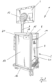
- FIGS. 1 to 5 show different views of a station trolley 1 according to the invention according to a first embodiment.
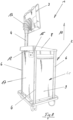
- a station trolley 1 according to the invention according to a second embodiment is shown in the Figures 6 to 12 , each also in different views.
- the two embodiments differ in particular with regard to a connecting device 18, which will be described in more detail below.
- the ward trolley 1 has, in a manner known per se, a cabinet part 2.
- This cabinet part 2 has a cabinet body 41 and a desk 8 supported by the cabinet body 41.
- a monitor 3 is provided, which is arranged on the cabinet part 2 by means of a column 4.
- the cabinet body 41 of the cabinet part 2 provides storage space for utensils.
- drawers 5 are provided for accommodating such utensils, which are arranged one above the other in the vertical direction 10.
- the cabinet body 41 has a total of four support struts 6 extending in the vertical direction 10, each of which is equipped with a support roller 7 to enable the cabinet part 2 to be moved. Opposite the support rollers 7 is the desk 8, supported by the support struts 6, which closes the top of the cabinet body 41.
- the cabinet body 41 further comprises side walls 9 and a rear wall 17, as can be seen from the first embodiment Fig. 2 and with regard to the second embodiment from Fig. 8
- the Figures 2 and 8 also recognize that the rear wall 17, in contrast to the prior art, is designed according to the DE 20 2012 101 860 U1 is not curved but flat.
- the cabinet body 41 also has handles 11 attached to the side walls 9.
- a crash barrier 12 is also provided, which is designed as a circumferential frame part. Unlike in the prior art, the rear section of the crash barrier 12 is not curved, but rather straight. This allows the station trolley 1, in a parked position, to be brought into linear contact with a This allows the device to be parked securely, which is possible with the state-of-the-art design according to DE 20 2012 101 860 U1 is not possible.
- the monitor 3 is arranged at the end of the column 4, the connecting area between column 4 and monitor 3 being covered by a sleeve 13, which is particularly advantageous for hygienic reasons.
- the column 4 has a connecting device 18 on the cabinet part side, with the column 4 being arranged outside the cabinet body 41 either on the cabinet body 41 or on the console 8.
- the arrangement of the connecting device 18 on the console is shown in the embodiment according to the Figures 1 to 5 , whereas the embodiment according to the Figures 6 to 12 shows the arrangement of the connecting device on the cabinet body 41.
- the arrangement of the connecting device 18 on the console 8 is according to the Figures 1 to 5 preferred.
- the connecting device 18 has a flange plate 42.
- This flange plate 42 is equipped with a recess 43 into which the column is inserted with its end section 44 remote from the monitor.
- the column 4 and the flange plate 42 are welded together.
- the console 8 On the cabinet body side, the console 8 has a recess 45 corresponding to the flange plate 42. The flange plate 42 is inserted into this recess 45 in the final assembled state. Screws 48 are provided to connect the flange plate 42 to the console 8.
- the flange plate 42 is flush with the underside of the console 8 facing the cabinet body.
- a cover 46 serves to cover the connecting device 18 in the final assembled state, as shown in Fig. 3 can be seen.
- the panel 46 is screwed to the console 8 using screws 47.
- the desk 8 preferably has a support plate 49 made of a wood material and a Cover 50 made of plastic.
- the cover 50 accommodates the carrier plate 49 in the manner of a hood open on one side.
- FIG. 12 The alternative embodiment according to the invention is shown in the Figures 6 to 12 Then a connecting device 18 is used, which is preferably as shown in Fig. 12 In the final assembled state, the connecting device 18 is arranged on the outside of the cabinet body 41, as can be seen, for example, from the detailed illustration according to Fig. 10 results.
- the cabinet body 41 of the cabinet part 2 has a frame 24, as shown in Fig. 11
- This frame 24 has two frames 25, each having an upper beam 27 in the vertical direction 10.
- the beams 27 are connected to one another with the interposition of two struts 26.
- Support struts 30 are also provided to connect the two beams 27, on which the console 8 rests in the final assembled state.
- the frames 25 also have lateral beams 28, each equipped with grooves 29. In these grooves 29, the Fig. 11 support struts 6 of the cabinet body 41, not shown in detail.
- the frame 24 has another brace, namely the stiffening brace 31.
- This brace is arranged on the corresponding beam 27 of the rear frame 25 on the one hand and on the support struts 30 on the other.
- This stiffening provides a permanently secure and stable arrangement of the column 4 on the cabinet body 41, as will be described in more detail below.
- the stiffening strut 31 has an opening 32 which is centrally positioned in the embodiment shown.
- the connecting device 18 is used to arrange the column 4 on the cabinet body 41, as they are particularly in Fig. 12 is shown.
- the connecting device 18 in turn has a flat material 34. This provides a first contact surface 35.
- two flat parts 37 are provided, which are welded to the flat material 34.
- the flat parts 37 with their underside facing the flat material 34, provide a second contact surface, namely the contact surface 38.
- Triangular side elements 40 are provided for additional reinforcement of the connecting device 18 and for additional connection of the flat material 34 to the flat parts 37. These are welded to both the flat material 34 and the flat parts 37.
- the connecting device 18 is preferably screwed to the frame 24 of the cabinet body 41, for which purpose both the flat material 34 and the flat parts 37 have corresponding bores 36 and 39, respectively.
- the column 4 has a recess 33 which is formed in the outer surface of the column 4.
- the final assembled state of the connecting device 18 is shown in particular in the illustration according to Fig. 10
- the connecting device 18 is arranged on the outside of the cabinet body 41.
- the contact surfaces 35 and 38 provided by the connecting device 18 rest against corresponding mating surfaces of the frame 24.
- the connecting device 18 is covered by the panel 8 protruding beyond the rear wall 17, so that it is not visible to a consumer from above.
- the connecting device 18 is arranged on the frame 24 with the rear wall 17 interposed, i.e., the rear wall 17 is located between the associated beam 27 of the frame 25 and the flat material 34 of the connecting device 18.
- Fig. 10 also shows that the rear wall 17 is provided with an inspection opening 16 through which any cables 22 housed in the storage space of the cabinet body 41 are accessible. Such cables 22 can reach up to the monitor 3, for which purpose the cables 22 are to be led through the opening 32 of the stiffening strut 31 and the recess 33 of the column 4.
- both the inspection opening 16 is covered by a flap 15 and the connecting device 18 is covered by a closure element 19.
- Corresponding screws 20 and 21 are provided for arranging the closure element 19 on the connecting device 18 and for arranging the flap 15 on the rear wall 17.
- the above-described construction offers the particular advantage that a flat rear wall 17 is used instead of a curved rear wall.
Landscapes
- Engineering & Computer Science (AREA)
- General Engineering & Computer Science (AREA)
- Health & Medical Sciences (AREA)
- Mechanical Engineering (AREA)
- Life Sciences & Earth Sciences (AREA)
- Nursing (AREA)
- Biomedical Technology (AREA)
- Animal Behavior & Ethology (AREA)
- General Health & Medical Sciences (AREA)
- Public Health (AREA)
- Veterinary Medicine (AREA)
- Casings For Electric Apparatus (AREA)
- Assembled Shelves (AREA)
Description
- Die Erfindung betrifft einen Stationswagen, insbesondere in der Ausgestaltung als Visiten- und/oder Pflegewagen für Krankenhäuser, Pflegeheime und sonstige Einrichtungen des Gesundheitswesens, mit einem Schrankteil, das einen frontseitig zugänglichen Stauraum zur Aufnahme von Utensilien aufweist, und mit einem am Schrankteil angeordneten Monitor, der von einer Säule getragen ist, wobei das Schrankteil einen den Stauraum bereitstellenden Schrankkorpus und ein vom Schrankkorpus getragenes Pult aufweist.
- Ein Stationswagen der eingangs genannten, das heißt gattungsgemäßen Art ist aus der
DE 20 2012 101 860 U1 bekannt. Alternativen sind bekannt ausUS2005/062238 ,US2015/227127 ,US2009/309466 ,US2002/013640 oderUS2012/323362 . - Gemäß dem aus der
DE 20 2012 101 860 U1 vorbekannten Stationswagen verfügt der Schrankkorpus des Schrankteils nicht nur über einen Stauraum zur Aufnahme von Utensilien, sondern auch über einen Kabelraum. Dabei ist der Kabelraum in Beschickungsrichtung des Stauraums hinter dem Stauraum angeordnet und vom Stauraum durch eine Zwischenwand getrennt. Der Kabelraum dient der Aufnahme von Kabeln, insbesondere von solchen, die bis zu dem von der Säule getragenen Monitor führen. Dabei ist die Säule nach Art eines Rohres ausgebildet und stellt zur Kabelführung ihrerseits einen Hohlraum bereit. - Zur sicheren Anordnung der den Monitor tragenden Säule am Schrankteil ragt die Säule mit ihrem monitorentfernten Ende bis in den Schrankkorpus hinein, und zwar bis in den vom Schrankkorpus bereitgestellten Kabelraum hinein. Dabei ist der Schrankkorpus rückwärtig von einer gebogen ausgebildeten Rückwand verschlossen, so dass das in den Kabelraum hineinragende Säulenende verwenderseitig weder zugänglich, noch sichtbar ist. Die Säule ist mithin innenseitig des Schrankkorpus am Schrankkorpus angeordnet.
- Der Schrankkorpus stellt zwei im Kabelraum in Höhenrichtung verlaufende Führungsstege bereit, an denen die Säule angeordnet ist, wobei die Führungsstege die Säule zwischen sich aufnehmen.
- Obgleich sich der aus der
DE 20 2012 101 860 U1 vorbekannte Stationswagen im alltäglichen Praxiseinsatz bewährt hat, ist dieser nicht frei von Nachteilen. So wird die nur eingeschränkte Manövrierfähigkeit als nachteilig empfunden, die sich dadurch ergibt, dass die zur Abdeckung der vom Schrankkorpus aufgenommenen Säule einschließlich der die Säule abstützenden Führungsstege vorgesehene Rückwand des Schrankteils gebogen, und zwar mit Bezug auf den Stauraum des Schrankkorpus nach außen gewölbt ausgebildet ist. - Es ist deshalb ausgehend vom vorbeschriebenen Stand der Technik die Aufgabe der Erfindung, einen Stationswagen der gattungsgemäßen Art dahingehend weiterzuentwickeln, dass konstruktionsbedingt eine vereinfachte verwenderseitige Handhabung ermöglicht ist.
- Zur Lösung dieser Aufgabe wird mit der Erfindung ein Stationswagen der eingangs genannten Art vorgeschlagen, der sich dadurch auszeichnet, dass die Säule schrankteilseitig eine Verbindungseinrichtung aufweist, unter deren Zwischenordnung die Säule außenseitig des Schrankkorpus am Pult angeordnet ist.
- Zur Anordnung der den Monitor tragenden Säule am Schrankteil kommt erfindungsgemäß eine Verbindungseinrichtung zum Einsatz, mittels welcher die Säule mit ihrem monitorentfernten Ende außerhalb des Schrankkorpus, das heißt außenseitig desselben positioniert ist. Die Säule ragt mithin nicht in den vom Schrankkorpus bereitgestellten Innenraum hinein, ist mithin nicht innenseitig desselben positioniert.
- Die Säule ist unter Zwischenordnung der Verbindungseinrichtung am Schrankteil angeordnet, wobei erfindungsgemäß zwei Alternativen vorgesehen sind. Die Säule kann unter Zwischenordnung der Verbindungseinrichtung entweder am Schrankkorpus oder am Pult angeordnet sein. In beiden Fällen ragt die Säule in schon vorbeschriebener Weise nicht in den vom Schrankkorpus bereitgestellten Innenraum hinein.
- In vorteilhafter Weise kann aufgrund der erfindungsgemäßen Konstruktion auf die ausladende Ausgestaltung nach dem Stand der Technik, wonach der Schrankkorpus über zwei in Höhenrichtung verlaufende Führungsstege verfügt, zwischen denen das monitorentfernte Ende der Säule angeordnet ist, vollends verzichtet werden. Auch der zur Unterbringung der Säule nach dem Stand der Technik vorgesehene Kabelraum ist nicht mehr vonnöten, da etwaige Kabel direkt aus den Stauraum des Schrankkorpus kommend durch die Säule bis zum Monitor geführt werden können.
- Der erfindungsgemäße Stationswagen ist damit bei gleichbleibend großem Stauraum weniger ausladend ausgebildet, was eine verwenderseitige vereinfachte Handhabung ermöglicht, insbesondere beim Manövrieren. Darüber hinaus benötigt der erfindungsgemäße Stationswagen weniger Stellfläche, was insbesondere im Falle des Nichtgebrauchs von Vorteil ist, da die benötigte Parkfläche minimiert ist.
- Die erfindungsgemäße Konstruktion erlaubt darüber hinaus auch deshalb eine vereinfachte Handhabung, weil der Stationswagen mit seiner rückwärtigen Seite sicher an einer Gebäudewand positioniert werden kann. Denn im Unterschied zum Stand der Technik fehlt es an einer gewölbt ausgebildeten Rückwand, die einen solch positionssicheren Berührungskontakt mit einer Raumwand nicht gestattet. Denn anders als die nach dem Stand der Technik vorbekannte Konstruktion ermöglicht es die erfindungsgemäße Ausgestaltung, einen rückwärtig des Stationswagens vorgesehenen Rammschutz planparallel zu einer Raumwand auszubilden. Eine Rammschutzausgestaltung ist nach der aus dem Stand der Technik vorbekannten Konstruktion nicht möglich.
- Die erfindungsgemäße Alternative, die Säule schrankteilseitig unter Zwischenordnung einer Verbindungseinrichtung am Pult anzuordnen, ist bevorzugt. Dies deshalb, weil so eine besonders einfache Konstruktion gegeben ist, die eine vereinfachte und damit preisgünstige Herstellung ermöglicht und die ferner insbesondere im Reparaturfall montage- bzw. demontagefreundlicher ist. Insbesondere die Zugänglichkeit der Verbindungseinrichtung ist bei einer Anordnung derselben am Pult verbessert.
- Gemäß einem weiteren Merkmal der Erfindung ist vorgesehen, dass die Säule und die Verbindungseinrichtung einstückig oder quasi einstückig ausgebildet sind. Die einstückige oder quasi einstückige Ausgestaltung von Säule und Verbindungseinrichtung ermöglicht insbesondere eine vereinfachte Endmontage. Die Säule und die Verbindungseinrichtung liegen mithin als einstückiges Bauteil vormontiert vor, so dass eine bestimmungsgemäße Anordnung der Säule am Schrankteil in einfacher Weise dadurch ermöglicht ist, dass die Säule unter Zwischenordnung der Verbindungseinrichtung außenseitig des Schrankkorpus entweder am Schrankkorpus selbst oder am Pult angeordnet wird. Eine solche Anordnung erfolgt durch Verschrauben.
- Gemäß der Erfindung ist vorgesehen, dass die Säule nach Art eines einseitig offenen Rohres ausgebildet ist und verbindungseinrichtungsseitig eine in einer Säulenwandung ausgebildete Ausnehmung aufweist. Durch diese Ausnehmung können schrankteilseitige Kabel in die Säule bis zum davon getragenen Monitor geführt werden. Dabei ist es besonders bevorzugt, als Monitor einen sogenannten All-in-one-Monitor zu verwenden, das heißt einen Monitor, in dessen Monitorgehäuse auch eine Rechnereinheit, eine batteriegestützte Stromversorgung sowie ein Energiemanagementsystem untergebracht sind. In diesem Fall bedarf es nur noch einer Kabelverbindung zum Monitor für etwaige Peripheriegeräte, wie zum Beispiel Tastatur und/oder Mouse. Derartige Peripheriegeräte können aber auch über Funk mit der vom Monitorgehäuse aufgenommenen Rechnereinheit in kommunikationstechnischer Verbindung stehen, so dass es in diesem Fall keinerlei Kabel bedarf.
- Gemäß der Erfindung weist die Verbindungseinrichtung eine Flanschplatte mit einer Ausnehmung auf, in welche Ausnehmung die Säule mit ihrem monitorentfernten Endabschnitt eingesetzt ist. Die Flanschplatte kann als einfaches Flachmaterial ausgebildet sein. Die zur Aufnahme des monitorentfernten Endabschnitts der Säule vorgesehene Ausnehmung ist bevorzugterweise als Bohrung ausgeführt, insbesondere als geschlitzte Bohrung, was ein Einführen des monitorentfernten Endabschnittes der Säule in die Ausnehmung vereinfacht. Im endmontierten Zustand ist der Säule von der die Ausnehmung der Flanschplatte begrenzenden Randkante zumindest teilweise umgeben, so dass in diesem Kontaktbereich eine Verbindung von Flanschplatte und Säule beispielsweise durch Schweißen und/oder Kleben stattfinden kann.
- Die Flanschplatte ermöglicht ein flächenhaftes Einleiten von im bestimmungsgemäßen Verwendungsfall auftretenden Tragkräften und -momenten, womit eine zu hohe Spitzenbelastung mit dem Vorteil vermieden ist, dass ein aus- oder abreißen der Flanschplatte vom Pult sicher vermieden ist.
- Gemäß einem weiteren Merkmal der Erfindung ist vorgesehen, dass das Pult schrankkorpusseitig eine korrespondierend zur Flanschplatte ausgebildete Vertiefung aufweist. In diese Vertiefung ist die Flanschplatte im endmontierten Zustand eingesetzt, so dass sich vorzugsweise ein bündiger Abschluss zwischen der Flanschplatte und der dem Schrankkorpus zugewandten Pultrückwand ergibt. Zudem dient die Vertiefung als Montagehilfe, was eine positionssichere Ausrichtung der Verbindungseinrichtung und der damit verbundenen Säule in vorteilhafter Weise sicherstellt.
- Gemäß einem weiteren Merkmal der Erfindung ist vorgesehen, dass die Verbindungseinrichtung mit dem Pult verschraubt ist. Die Flanschplatte weist zu diesem Zweck Bohrungen auf, durch die hindurch die Verbindungsschrauben im endmontierten Zustand geführt sind. Ein Verschrauben von Verbindungseinrichtung und Pult ist insbesondere aus Gründen der Demontierbarkeit im Reparaturfall bevorzugt. Aber auch ein Pultaustausch ist so in einfacher Weise ermöglicht. Dabei findet eine Demontage des Pults nicht nur im Reparaturfall statt, sondern auch aus hygienischen Gründen. Die erfindungsgemäße Ausgestaltung ermöglicht es mithin, ein Pult sowohl im konkreten Bedarfsfall als auch standardisiert im Wartungsfall insbesondere aus hygienischen Gründen in einfacher Weise austauschen zu können. Die Möglichkeit des Austausches ist bei aus dem Stand der Technik bekannten Konstruktionen nicht gegeben, weil hier typischerweise nicht lösbare Verbindungen, insbesondere Schweiß-Verbindungen vorgesehen sind. Die erfindungsgemäße Ausgestaltung zeichnet sich deshalb in vorteilhafter Weise gegenüber dem Stand der Technik durch ihre Nachhaltigkeit aus. Denn es ist weder im Reparaturfall noch aus Hygienegründen erforderlich, den gesamten Stationswagen auszutauschen. Das Schrankteil kann vielmehr wiederverwendet und im Bedarfsfall mit einem neuen Pult ausgerüstet werden.
- Gemäß einem weiteren Merkmal der Erfindung ist eine die Vertiefung schrankkorpusseitig abdeckende Blende vorgesehen. Es ist so ein visuell ansprechender Abschluss gegeben und zudem sichergestellt, dass nicht ungewollt Verschmutzungen in die hohl ausgebildete Säule eindringen können.
- Gemäß einer alternativen Ausgestaltung der Erfindung ist vorgesehen, dass die Verbindungseinrichtung nicht über eine Flanschplatte der vorbeschriebenen Art, sondern über zwei senkrecht zueinander ausgerichtete Anlageflächen verfügt. Die Ausgestaltung einer solchen Verbindungseinrichtung ist bevorzugt, wenn die Säule unter Zwischenordnung der Verbindungseinrichtung nicht am Pult, sondern am Schrankkorpus angeordnet ist. Im endmontierten Zustand liegen bei dieser Ausgestaltungsform die Anlageflächen der Verbindungseinrichtung an entsprechenden Gegenflächen des Schrankkorpus an, so dass eine insgesamt dauerhaft sichere und stabile Anordnung der den Monitor tragenden Säule am Schrankteil sichergestellt ist. Da die Anlageflächen senkrecht zueinanderstehen, können als sämtlichen Richtungen Torsions- und Biegebeanspruchungen aufgenommen und in den Schrankkorpus überführt werden.
- Gemäß einem weiteren Merkmal der Erfindung ist vorgesehen, dass der Schrankkorpus ein Gestell mit einem Rahmen aufweist, an welchem Rahmen eine ebenflächig ausgebildete Rückwand angeordnet ist.
- Die ebenflächig ausgebildete Rückwand ist in vorteilhafter Weise deshalb realisierbar, weil in schon vorbeschriebener Weise auf einen zum Stauraum zusätzlichen Raum zur Aufnahme des monitorentfernten Endes der Säule verzichtet ist. Mittels der erfindungsgemäß vorgesehenen Verbindungseinrichtung ist die Säule außenseitig des Schrankkorpus entweder am Schrankkorpus oder am Pult angeordnet, so dass sich anstelle des nach dem Stand der Technik vorgesehenen Kabelraums in Höhenrichtung unterhalb der Verbindungseinrichtung ein Freiraum einstellt. Im Unterschied zum Stand der Technik kann die Rückwand infolge dieser Ausgestaltung ebenflächig ausgebildet sein, da es einer außenseitigen Abdeckung dieses Freiraumes nicht bedarf. Dabei ist die ebenflächig ausgebildete Rückwand direkt am Gestell des Schrankkorpus angeordnet, womit ein einfacher Aufbau und eine damit einhergehende einfache Montage gegeben sind.
- Gemäß einem weiteren Merkmal der Erfindung ist vorgesehen, dass das Gestell verbindungseinrichtungsseitig über eine Aussteifungsstrebe verfügt. Die Aussteifungsstrebe des Gestells sorgt zusätzlich für eine dauerhaft sichere und stabile Ausgestaltung des Schrankteils insgesamt, was eine positionssichere Anordnung der Säule am Schrankteil unterstützt. Zudem wird die Verwindungssteifigkeit des Gestells erhöht, so dass auch etwaige Querbelastungen besser aufgenommen werden können.
- Gemäß einem weiteren Merkmal der Erfindung ist vorgesehen, dass die Verbindungseinrichtung gemäß der alternativen Ausführungsform mit ihren Anlageflächen an der Aussteifungsstrebe einerseits und an einem Holm des Rahmens andererseits anliegt. Es ist so die schon vorbeschriebene dauerhaft sichere und stabile Anordnung der Verbindungseinrichtung am Schrankkorpus gewährleistet.
- Gemäß einem weiteren Merkmal der Erfindung ist in diesem Zusammenhang vorgesehen, dass die Verbindungseinrichtung mit der Aussteifungsstrebe und dem Holm verschraubt ist. Es ist so eine einfache Montage gewährleistet, und dies bei gleichzeitiger Möglichkeit einer einfachen Demontage, insbesondere im Reparaturfall.
- Gemäß einem weiteren Merkmal der Erfindung ist in diesem Zusammenhang ferner vorgesehen, dass die Verbindungseinrichtung unter Zwischenschaltung der Rückwand mit dem Holm verschraubt ist. Auch durch diese konstruktive Maßnahme wird eine vereinfachte Montage zusätzlich unterstützt. Alternativ kann die Rückwand mit einer Ausklinkung für Verbindungseinrichtung ausgerüstet sein.
- Gemäß einem weiteren Merkmal der Erfindung wird in diesem Zusammenhang ferner vorgeschlagen, dass die Aussteifungsstrebe eine Öffnung bereitstellt. Durch diese Öffnung kann im Bedarfsfall eine bis in die Säule reichende Verkabelung geführt werden. Zu diesem Zweck ist gemäß einem weiteren Merkmal der Erfindung vorgesehen, dass die von der Aussteifungsstrebe bereitgestellte Öffnung mit der säulenseitigen Ausnehmung zusammenwirkt. Es ist so ein insgesamt kompakter und platzsparender Aufbau gegeben. Ein etwaiges Kabel kann aus dem Stauraum durch die von der Aussteifungstrebe bereitgestellte Öffnung hindurch direkt durch die säulenseitige Ausnehmung in die Säule geführt werden. Es ist so eine kurze Kabelwegstrecke sichergestellt.
- Gemäß der Erfindungsalternative ist es bevorzugterweise des Weiteren vorgesehen, dass das Pult die Verbindungseinrichtung oberseitig abdeckt. Damit ist die Verbindungseinrichtung quasi unterhalb des Pults versteckt angeordnet, so dass sie von oben für einen Verbraucher nicht einsehbar ist. Es ist so ein optisch ansprechender Eindruck sichergestellt. Ferner ergibt sich durch diese Konstruktion, dass die Verbindungseinrichtung zumindest abschnittsweise zwischen dem korpusseitigen Gestell einerseits und dem Pult andererseits angeordnet ist, was aus Stabilitätsgründen von Vorteil ist.
- Gemäß einem weiteren Merkmal der Erfindung ist vorgesehen, dass das Pult verbindungseinrichtungsseitig eine Öffnung zur Durchführung der Säule aufweist. Bei einer Anordnung der Verbindungseinrichtung am Schrankkorpus übernimmt das Pult mithin hinsichtlich der Säule keine tragende oder abstützende Funktion. Allein die erfindungsgemäß vorgesehene Verbindungseinrichtung dient der Anordnung der Säule am Schrankkorpus, wobei das Pult den Schrankkorpus oberseitig abdeckt und zur Hindurchführung der Säule eine entsprechende Öffnung bereitstellt.
- Gemäß der bevorzugten Ausführungsform ist die Verbindungseinrichtung direkt am Pult angeordnet, in welchem Fall eine tragende und abstützende Funktion aufnimmt. Dabei werden über die Verbindungseinrichtung in das Pult eingeleitete Kräfte und/oder Momente in das Gestell des Schrankkorpus abgeleitet, da das Pult mit diesem verbunden, vorzugsweise verschraubt ist.
- Mit Blick auf die erfindungsgemäße Ausgestaltung geht eine Endmontage in einfacher Weise wie folgt vonstatten. In einem ersten Montageschritt ist zur rückwärtigen Abdeckung des Schrankkorpus die dafür vorgesehene Rückwand am Gestell des Schrankkorpus anzubringen. Gemäß der bevorzugten Ausführungsform ist alsdann die Säule unter Zwischenordnung der erfindungsgemäßen Verbindungseinrichtung am Pult anzubringen. Alsdann kann das Pult zusammen mit der Säule und dem davon getragenen Monitor am Gestell des Schrankkorpus angebracht werden. Gemäß der alternativen Ausführungsform erfolgt in einem zweiten Montageschritt zunächst die Anordnung der Säule am Schrankkorpus, und zwar unter Verwendung der hierfür entsprechend ausgebildeten Verbindungseinrichtung. Alsdann ist das Pult zu montieren, das von oben auf den Schrankkorpus aufzusetzen ist, wobei die schon montierte Säule durch die vom Pult bereitgestellte Öffnung zu führen ist. In einem letzten Montageschritt ist dann der Monitor am freien Ende der Säule anzubringen.
- Gemäß einem weiteren Merkmal der Erfindung ist vorgesehen, dass die Verbindungseinrichtung ein die schrankteilseitige Stirnöffnung der Säule abdeckendes Verschlusselement aufweist. Dieses Verschlusselement kann nach Art einer Kappe ausgebildet sein und dient dazu, die stirnseitig offen ausgebildete Säule abzudecken. Ein ungehinderter Zugriff auf etwaige von der Säule beherbergte Kabel ist so vermieden.
- Gemäß einem weiteren Merkmal der Erfindung ist vorgesehen, dass die Rückwand eine Revisionsöffnung aufweist. Durch diese Revisionsöffnung ist insbesondere der direkt unterhalb des Pults befindliche Stauraum des Schrankkorpus zugänglich. Im Falle etwaiger vom Schrankkorpus aufgenommener Peripheriegeräte ist so ein vereinfachter Zugriff auf etwaige zu den Peripheriegeräten führende Kabel ermöglicht.
- Weitere Merkmale und Vorteile der Erfindung ergeben sich aus der nachfolgenden Beschreibung anhand der Figuren. Dabei zeigen:
- Fig. 1
- in schematisch perspektivischer Frontansicht einen erfindungsgemäßen Stationswagen gemäß einer ersten Ausführungsform;
- Fig. 2
- in schematisch perspektivischer Rückansicht den Stationswagen nach
Fig. 1 ; - Fig. 3
- in schematischer Detailansicht einen Ausschnitt des Stationswagens nach
Fig. 2 ; - Fig. 4
- in einer schematischen Detailansicht den Ausschnitt nach
Fig. 3 mit abgenommener Blende; - Fig. 5
- in schematischer Draufsicht von unten das Pult des Stationswagens nach
Fig. 1 ; - Fig. 6
- in schematisch perspektivischer Frontansicht einen erfindungsgemäßen Stationswagen gemäß einer zweiten Ausführungsform;
- Fig. 7
- in schematischer Seitenansicht den Stationswagen nach
Fig. 6 ; - Fig. 8
- in schematisch perspektivischer Rückansicht den Stationswagen nach
Fig. 6 ; - Fig. 9
- in schematischer Detailansicht einen Ausschnitt des Stationswagens nach
Fig. 8 ; - Fig. 10
- in einer weiteren Detailansicht den Stationswagen nach
Fig. 8 ; - Fig. 11
- in schematischer Perspektivdarstellung ein Gestell des erfindungsgemäßen Stationswagens und
- Fig. 12
- in schematischer Perspektivansicht ausschnittsweise eine Säule einschließlich einer Verbindungseinrichtung gemäß der zweiten Ausführungsform.
- Die
Figuren 1 bis 5 lassen in unterschiedlichen Ansichten einen erfindungsgemäßen Stationswagen 1 gemäß einer ersten Ausführungsform erkennen. Einen erfindungsgemäßen Stationswagen 1 gemäß einer zweiten Ausführungsform zeigen dieFiguren 6 bis 12 , jeweils ebenfalls in unterschiedlichen Ansichten. Die beiden Ausführungsformen unterscheiden sich insbesondere hinsichtlich einer im Weiteren noch näher beschriebenen Verbindungseinrichtung 18. - Der erfindungsgemäße Stationswagen 1 verfügt in an sich bekannter Weise über ein Schrankteil 2. Dieses Schrankteil 2 weist seinerseits einen Schrankkorpus 41 und ein vom Schrankkorpus 41 getragenes Pult 8 auf. Es ist ferner ein Monitor 3 vorgesehen, der mittels einer Säule 4 am Schrankteil 2 angeordnet ist.
- Der Schrankkorpus 41 des Schrankteils 2 stellt einen Stauraum zur Aufnahme von Utensilien bereit. Gemäß der gezeigten Ausführungsbeispiele sind zur Aufnahme derlei Utensilien Schubladen 5 vorgesehen, die in Höhenrichtung 10 übereinander angeordnet sind.
- Der Schrankkorpus 41 verfügt über insgesamt vier sich in Höhenrichtung 10 erstreckende Tragstreben 6, die jeweils zur verfahrbaren Ausgestaltung des Schrankteils 2 mit einer Tragrolle 7 ausgerüstet sind. Den Tragrollen 7 gegenüberliegend ist das von den Tragstreben 6 abgestützt Pult 8 vorgesehen, welches den Schrankkorpus 41 oberseitig verschließt.
- Der Schrankkorpus 41 verfügt des Weiteren über Seitenwände 9 sowie über eine Rückwand 17, wie sich dies hinsichtlich des ersten Ausführungsbeispiels aus
Fig. 2 und hinsichtlich des zweiten Ausführungsbeispiels ausFig. 8 ergibt. Dabei lassen dieFiguren 2 und8 jeweils auch erkennen, dass die Rückwand 17 im Unterschied zum Stand der Technik nach derDE 20 2012 101 860 U1 nicht gewölbt, sondern ebenflächig ausgebildet ist. - Für eine bessere Manövrierfähigkeit verfügt der Schrankkorpus 41 zudem über an den Seitenwänden 9 angebrachte Griffe 11.
- Für einen Schutz des Schrankkorpus 41 vor möglichen Kollisionen ist zudem ein Rammschutz 12 vorgesehen, der als umlaufendes Rahmenteil ausgebildet ist. Dabei ist der rückwärtige Abschnitt des Rammschutzes 12 im Unterschied zum Stand der Technik nicht gebogen, sondern gradlinig verlaufend ausgebildet. Dies gestattet es, den Stationswagen 1 in einer Parkposition in einen linienförmigen Berührungskontakt mit einer Raumwand zu bringen. Dies ermöglicht die Einnahme einer positionssicheren Parkstellung, was bei der Konstruktion nach dem Stand der Technik gemäß der
DE 20 2012 101 860 U1 nicht möglich ist. - Wie sich insbesondere aus einer Zusammenschau der
Figuren 2 einerseits und 7 bzw. 8 andererseits ergibt, ist der Monitor 3 endseitig der Säule 4 angeordnet, wobei der Verbindungsbereich zwischen Säule 4 und Monitor 3 durch eine Manschette 13 abgedeckt ist, was insbesondere aus hygienischen Gründen von Vorteil ist. - Die Säule 4 weist erfindungsgemäß schrankteilseitig eine Verbindungseinrichtung 18 auf, unter deren Zwischenordnung die Säule 4 außenseitig des Schrankkorpus 41 entweder am Schrankkorpus 41 oder am Pult 8 angeordnet ist. Die Anordnung der Verbindungseinrichtung 18 am Pult zeigt das Ausführungsbeispiel nach den
Figuren 1 bis 5 , wohingegen das Ausführungsbeispiel nach denFiguren 6 bis 12 die Anordnung der Verbindungseinrichtung am Schrankkorpus 41 zeigt. Dabei ist die Anordnung der Verbindungseinrichtung 18 am Pult 8 gemäß derFiguren 1 bis 5 bevorzugt. - Wie sich aus einer Zusammenschau insbesondere der
Figuren 4 und5 ergibt, weist die Verbindungseinrichtung 18 eine Flanschplatte 42 auf. Diese Flanschplatte 42 ist mit einer Ausnehmung 43 ausgerüstet, in die die Säule mit ihrem monitorentfernten Endabschnitt 44 eingesetzt ist. Zwecks quasi einstückiger Ausbildung sind die Säule 4 und die Flanschplatte 42 miteinander verschweißt. - Das Pult 8 weist schrankkorpusseitig eine korrespondierend zur Flanschplatte 42 ausgebildete Vertiefung 45 auf. In diese Vertiefung 45 ist die Flanschplatte 42 im endmontierten Zustand eingesetzt. Zur Verbindung der Flanschplatte 42 mit dem Pult 8 ist eine Verschraubung mittels der Schrauben 48 vorgesehen.
- Wie insbesondere die Darstellung nach
Fig. 4 erkennen lässt, schließt die Flanschplatte 42 bündig mit der Schrankkorpus zugewandten Unterseite des Pults 8 ab. Zur Abdeckung der Verbindungseinrichtung 18 im endmontierten Zustand dient eine Blende 46, wie inFig. 3 zu erkennen ist. Dabei ist die Blende 46 mittels Schrauben 47 mit dem Pult 8 verschraubt. - Das Pult 8 weist sowohl gemäß der ersten als auch gemäß der zweiten Ausführungsform vorzugsweise eine Trägerplatte 49 aus einem Holzwerkstoff und eine damit verklebte Abdeckung 50 aus Kunststoff auf. Dabei nimmt die Abdeckung 50 die Trägerplatte 49 nach Art einer einseitig offen ausgebildeten Haube auf.
- Im alltäglichen Praxisgebrauch kommt es häufig insbesondere zu einer Abnutzung und/oder Verschmutzung der Haube 50 des Pults 8. Die erfindungsgemäße Ausgestaltung vereinfacht einen Pultaustausch, da es für eine Demontierung lediglich erforderlich ist, die Schrauben 48 zu lösen, mittels welcher die Flanschplatte 42 am Pult 8 angebracht ist.
- Die nach der Erfindung alternative Ausgestaltung ist in den
Figuren 6 bis 12 gezeigt. Danach kommt eine Verbindungseinrichtung 18 zum Einsatz, die vorzugsweise wie inFig. 12 dargestellt ausgebildet ist. Im endmontierten Zustand ist die Verbindungseinrichtung 18 außenseitig des Schrankkorpus 41 am Schrankkorpus 41 angeordnet, wie sich dies beispielsweise aus der Detaildarstellung nachFig. 10 ergibt. - Der Schrankkorpus 41 des Schrankteils 2 verfügt über ein Gestell 24, wie dieses in
Fig. 11 dargestellt ist. Dieses Gestell 24 verfügt über zwei Rahmen 25, die jeweils einen in Höhenrichtung 10 oberen Holm 27 aufweisen. Dabei sind die Holme 27 unter Zwischenordnung zweiter Streben 26 miteinander verbunden. Zur Verbindung der beiden Holme 27 sind des Weiteren Stützstreben 30 vorgesehen, auf denen im endmontierten Zustand das Pult 8 aufliegt. - Die Rahmen 25 verfügen des Weiteren über seitliche Holme 28, die jeweils mit Nuten 29 ausgerüstet sind. In diesen Nuten 29 kommen im endmontierten Zustand die in
Fig. 11 nicht näher dargestellten Tragstreben 6 des Schrankkorpus 41 zu liegen. - Da Gestell 24 verfügt über eine weitere Strebe, nämlich die Aussteifungsstrebe 31. Diese ist am zugehörigen Holm 27 des rückwärtigen Rahmens 25 einerseits und an den Stützstreben 30 andererseits angeordnet. Es findet so eine Aussteifung statt, die, wie dies im Weiteren noch näher beschrieben werden wird, einer dauerhaft sicheren und stabilen Anordnung der Säule 4 am Schrankkorpus 41 dient.
- Wie aus
Fig. 11 ferner ersichtlich ist, verfügt die Aussteifungsstrebe 31 über eine im gezeigten Ausführungsbeispiel mittig platzierte Öffnung 32. - Zur Anordnung der Säule 4 am Schrankkorpus 41 dient die Verbindungseinrichtung 18, wie sie insbesondere in
Fig. 12 dargestellt ist. - Die Verbindungseinrichtung 18 verfügt ihrerseits über ein Flachmaterial 34. Dieses stellt eine erste Anlagefläche 35 bereit.
- Es sind des Weiteren zwei Flachteile 37 vorgesehen, die mit dem Flachmaterial 34 verschweißt sind. Die Flachteile 37 stellen mit ihrer dem Flachmaterial 34 zugewandten Unterseite eine zweite Anlagefläche bereit, nämlich die Anlagefläche 38.
- Für eine zusätzliche Aussteifung der Verbindungseinrichtung 18 sowie für eine zusätzliche Verbindung des Flachmaterials 34 mit den Flachteilen 37 sind dreieckförmig ausgebildete Seitenelemente 40 vorgesehen. Diese sind sowohl mit dem Flachmaterial 34 als auch mit den Flachteilen 37 verschweißt.
- Im endmontierten Zustand ist die Verbindungseinrichtung 18 bevorzugterweise mit dem Gestell 24 des Schrankkorpus 41 verschraubt, zu welchem Zweck sowohl das Flachmaterial 34 als auch die Flachteile 37 entsprechende Bohrungen 36 bzw. 39 aufweisen.
- Wie sich aus
Fig. 12 des Weiteren ergibt, weist die Säule 4 eine Ausnehmung 33 auf, die in der Mantelfläche der Säule 4 ausgebildet ist. - Der endmontierte Zustand der Verbindungseinrichtung 18 ergibt sich insbesondere aus der Darstellung nach
Fig. 10 . Wie diese Figur erkennen lässt, ist die Verbindungseinrichtung 18 außenseitig des Schrankkorpus 41 am Schrankkorpus 41 angeordnet. Dabei liegen die von der Verbindungseinrichtung 18 bereitgestellten Anlageflächen 35 und 38 an entsprechenden Gegenflächen des Gestells 24 an. Oberseitig ist die Verbindungseinrichtung 18 mittels des über die Rückwand 17 hinaus vorstehenden Pults 8 abgedeckt, so dass sie von oben für einen Verbraucher nicht sichtbar ist. Im gezeigten Ausführungsbeispiel ist die Verbindungseinrichtung 18 unter Zwischenordnung der Rückwand 17 am Gestell 24 angeordnet, das heißt die Rückwand 17 befindet sich zwischen dem zugehörigen Holm 27 des Rahmens 25 und dem Flachmaterial 34 der Verbindungseinrichtung 18. -
Fig. 10 lässt ferner erkennen, dass die Rückwand 17 mit einer Revisionsöffnung 16 ausgerüstet ist, durch die hindurch etwaige vom Stauraum des Schrankkorpus 41 beherbergte Kabel 22 zugänglich sind. Derartige Kabel 22 können bis zum Monitor 3 reichen, zu welchem Zweck die Kabel 22 durch die Öffnung 32 der Aussteifungsstrebe 31 und die Ausnehmung 33 der Säule 4 zu führen sind. Über eine solche Revisionsöffnung 16 kann auch die schon vorbeschriebenen Ausführungsform nach denFiguren 1 bis 5 verfügen, wie in den Figuren dargestellt ist. -
Fig. 9 lässt schließlich noch erkennen, dass im endmontierten Zustand sowohl die Revisionsöffnung 16 mittels einer Klappe 15 als auch die Verbindungseinrichtung 18 mittels eines Verschlusselements 19 abgedeckt sind. Zur Anordnung des Verschlusselements 19 an der Verbindungseinrichtung 18 bzw. zur Anordnung der Klappe 15 an der Rückwand 17 sind entsprechende Schrauben 20 bzw. 21 vorgesehen. - Wie insbesondere die Darstellung nach den
Figuren 7 und8 erkennen lässt, erbringt die vorbeschriebene Konstruktion insbesondere den Vorteil mit sich, dass anstelle einer gebogenen Rückwand eine ebenflächig ausgebildete Rückwand 17 zum Einsatz kommt. Dadurch entsteht in Höhenrichtung 10 unterhalb der Säule 4 ein Freiraum 14, so dass der erfindungsgemäße Stationswagen 1 im Unterschied zum Stand der Technik weniger ausladend ausgebildet ist und bei gleich großem Stauraum in Beschickungsrichtung des Stauraums in seinen geometrischen Abmessungen kleiner ausgebildet ist. Dies erbringt eine verbesserte Manövrierfähigkeit und minimiert die im Nichtgebrauchsfall benötigte Parkfläche. -
- 1
- Stationswagen
- 2
- Schrankteil
- 3
- Monitor
- 4
- Säule
- 5
- Schublade
- 6
- Tragstrebe
- 7
- Tragrolle
- 8
- Pult
- 9
- Seitenwand
- 10
- Höhenrichtung
- 11
- Griff
- 12
- Rammschutz
- 13
- Manschette
- 14
- Freiraum
- 15
- Klappe
- 16
- Revisionsöffnung
- 17
- Rückwand
- 18
- Verbindungseinrichtung
- 19
- Verschlusselement
- 20
- Schraube
- 21
- Schraube
- 22
- Kabel
- 23
- Schraube
- 24
- Gestell
- 25
- Rahmen
- 26
- Strebe
- 27
- Holm
- 28
- Holm
- 29
- Nut
- 30
- Stützstrebe
- 31
- Aussteifungsstrebe
- 32
- Öffnung
- 33
- Ausnehmung
- 34
- Flachmaterial
- 35
- Anlagefläche
- 36
- Bohrung
- 37
- Flachteil
- 38
- Anlagefläche
- 39
- Bohrung
- 40
- Seitenelement
- 41
- Schrankkorpus
- 42
- Flanschplatte
- 43
- Ausnehmung
- 44
- Endabschnitt
- 45
- Vertiefung
- 46
- Blende
- 47
- Schraube
- 48
- Schraube
- 49
- Trägerplatte
- 50
- Abdeckung
Claims (6)
- Stationswagen, insbesondere Visiten- und/oder Pflegewagen für Krankenhäuser, Pflegeheime und sonstige Einrichtungen des Gesundheitswesens, mit einem Schrankteil (2), das einen frontseitig zugänglichen Stauraum zur Aufnahme von Utensilien aufweist, und mit einem am Schrankteil (2) angeordneten Monitor (3), der von einer Säule (4) getragen ist, wobei das Schrankteil (2) einen den Stauraum bereitstellenden Schrankkorpus (41) und ein vom Schrankkorpus (41) getragenes Pult (8) aufweist und wobei die Säule (4) schrankteilseitig eine Verbindungseinrichtung (18) aufweist, unter deren Zwischenordnung die Säule (4) außenseitig des Schrankkorpus (41) am Pult (8) angeordnet ist,
dadurch gekennzeichnet,
dass die Säule (4) nach Art eines einseitig offenen Rohres ausgebildet ist und verbindungseinrichtungsseitig eine in einer Säulenwandung ausgebildete Ausnehmung (33) aufweist und dass die Verbindungseinrichtung (18) eine Flanschplatte (42) mit einer Ausnehmung (43) aufweist, in welche Ausnehmung (43) die Säule (4) mit ihrem monitorentfernten Endabschnitt (44) eingesetzt ist, wobei das Pult (8) schrankkorpusseitig eine korrespondierend zur Flanschplatte (42) ausgebildete Vertiefung (45) aufweist, in die die Flanschplatte (42) eingesetzt ist, so dass sich ein bündiger Abschluss zwischen der Flanschplatte (42) und der dem Schrankkorpus (41) zugewandten Pultrückwand ergibt, und wobei die Flanschplatte (42) mit dem Pult (8) verschraubt ist. - Stationswagen nach Anspruch 1, dadurch gekennzeichnet, dass die Säule (4) und die Verbindungseinrichtung (18) einstückig oder quasi einstückig ausgebildet sind.
- Stationswagen nach Anspruch 1, gekennzeichnet durch eine die Vertiefung (45) schrankkorpusseitig abdeckende Blende (46).
- Stationswagen nach einem der vorhergehenden Ansprüche, dadurch gekennzeichnet, dass der Schrankkorpus (41) ein Gestell (24) mit einem Rahmen (25) aufweist, an welchem Rahmen (25) eine ebenflächig ausgebildete Rückwand (17) angeordnet ist.
- Stationswagen nach Anspruch 4, dadurch gekennzeichnet, dass das Gestell (24) verbindungseinrichtungsseitig über eine Aussteifungsstrebe (31) verfügt.
- Stationswagen nach einem der vorhergehenden Ansprüche, dadurch gekennzeichnet, dass das Pult (8) eine Trägerplatte (49) aus einem Holzwerkstoff und eine damit verklebte Abdeckung (50) aus Kunststoff aufweist, wobei die Abdeckung (50) die Trägerplatte (49) nach Art einer einseitig offen ausgebildeten Haube aufnimmt.
Applications Claiming Priority (1)
| Application Number | Priority Date | Filing Date | Title |
|---|---|---|---|
| DE202021103941.8U DE202021103941U1 (de) | 2021-07-23 | 2021-07-23 | Stationswagen, insbesondere Visiten- und/oder Pflegewagen |
Publications (2)
| Publication Number | Publication Date |
|---|---|
| EP4122438A1 EP4122438A1 (de) | 2023-01-25 |
| EP4122438B1 true EP4122438B1 (de) | 2025-05-14 |
Family
ID=80625137
Family Applications (1)
| Application Number | Title | Priority Date | Filing Date |
|---|---|---|---|
| EP22159800.6A Active EP4122438B1 (de) | 2021-07-23 | 2022-03-02 | Stationswagen, insbesondere visiten- und/oder pflegewagen |
Country Status (2)
| Country | Link |
|---|---|
| EP (1) | EP4122438B1 (de) |
| DE (1) | DE202021103941U1 (de) |
Family Cites Families (8)
| Publication number | Priority date | Publication date | Assignee | Title |
|---|---|---|---|---|
| US6339732B1 (en) * | 1998-10-16 | 2002-01-15 | Pyxis Corporation | Apparatus and method for storing, tracking and documenting usage of anesthesiology items |
| WO2004088463A2 (en) * | 2003-03-28 | 2004-10-14 | Cardinal Health 301, Inc. | Point of care station |
| US8708352B2 (en) * | 2008-06-11 | 2014-04-29 | Bracco Diagnostics Inc. | Cabinet structure configurations for infusion systems |
| US9355219B2 (en) * | 2011-05-02 | 2016-05-31 | Omnicell, Inc. | Dispensing cabinet with articulating arm |
| DE202012101860U1 (de) | 2012-05-22 | 2012-07-05 | Optiplan Gesellschaft für optische Planungsgeräte mbH | Stationswagen, insbesondere Visiten- und Pflegewagen |
| US9367061B2 (en) * | 2014-02-07 | 2016-06-14 | Enovate Medical, Llc | Medical cart for dispensing medication |
| DE202015106146U1 (de) | 2015-11-13 | 2015-12-18 | Optiplan Gesellschaft für optische Planungsgeräte mit beschränkter Haftung | Stationswagen |
| DE102018006682A1 (de) | 2018-08-23 | 2020-02-27 | Dirk Maurer | Vorrichtung zum Halten mehrere Monitore |
-
2021
- 2021-07-23 DE DE202021103941.8U patent/DE202021103941U1/de not_active Expired - Lifetime
-
2022
- 2022-03-02 EP EP22159800.6A patent/EP4122438B1/de active Active
Also Published As
| Publication number | Publication date |
|---|---|
| EP4122438A1 (de) | 2023-01-25 |
| DE202021103941U1 (de) | 2022-10-25 |
Similar Documents
| Publication | Publication Date | Title |
|---|---|---|
| EP2611331B1 (de) | Möbelauszugsteil | |
| EP3316734B1 (de) | Schublade mit einer bodenplatte, zwei seitenwänden, einer rückwand und einer blende | |
| EP0940105A2 (de) | Ausziehvorrichtung für Hochschränke | |
| EP1716779B1 (de) | Bodenlose Schublade und Aufnahmerahmen dafür | |
| EP2643181B1 (de) | Frontendmodul-anordnung für eine karosserie eines personenkraftwagens | |
| EP0179410A2 (de) | Tisch, insbesondere reihfähiger Konferenztisch | |
| DE102010017174A1 (de) | Gelenk und klappbares Möbelteil | |
| EP2666452A1 (de) | Stationswagen, insbesondere Visiten- und Pflegewagen | |
| EP0663166B1 (de) | Schublade | |
| EP1793702A1 (de) | Möbelschublade | |
| EP2774634B1 (de) | Dialysemaschine mit selbsttragendem Maschinengehäuse | |
| EP3318238B1 (de) | Stationswagen | |
| EP2063735B1 (de) | Tisch, insbesondere schülertisch | |
| EP3426527B1 (de) | Fahrzeug für den öffentlichen personenverkehr | |
| EP4122438A1 (de) | Stationswagen, insbesondere visiten- und/oder pflegewagen | |
| DE102017114389A1 (de) | Anordnung aus einem Schaltschranksockel und einem darauf montierten Schaltschrankrahmengestell sowie eine entsprechende Schaltschrankreihe | |
| EP1676500B1 (de) | Bodenseitiger Schubkasten für ein Stellmöbel | |
| EP3804562B1 (de) | Unterbauschublade | |
| DE69019104T2 (de) | Aufbau-Möbeleinheit. | |
| EP3685705B1 (de) | Betriebseinrichtung mit zwei profilen und einer wand | |
| EP0632980B1 (de) | Beschlag für klappbare Möbelstücke | |
| DE8525402U1 (de) | Bausatz für eine rollbare Transportplattform | |
| DE102014109712B4 (de) | Schrankmöbel und Verfahren zur Montage eines Schrankmöbels | |
| EP1144271B1 (de) | Verpackung fur die bestandteile eines zerlegten schaltschrankes | |
| EP3623632B1 (de) | Modulares rahmensystem für vakuumpumpen |
Legal Events
| Date | Code | Title | Description |
|---|---|---|---|
| PUAI | Public reference made under article 153(3) epc to a published international application that has entered the european phase |
Free format text: ORIGINAL CODE: 0009012 |
|
| STAA | Information on the status of an ep patent application or granted ep patent |
Free format text: STATUS: THE APPLICATION HAS BEEN PUBLISHED |
|
| AK | Designated contracting states |
Kind code of ref document: A1 Designated state(s): AL AT BE BG CH CY CZ DE DK EE ES FI FR GB GR HR HU IE IS IT LI LT LU LV MC MK MT NL NO PL PT RO RS SE SI SK SM TR |
|
| P01 | Opt-out of the competence of the unified patent court (upc) registered |
Effective date: 20230517 |
|
| STAA | Information on the status of an ep patent application or granted ep patent |
Free format text: STATUS: REQUEST FOR EXAMINATION WAS MADE |
|
| 17P | Request for examination filed |
Effective date: 20230621 |
|
| RBV | Designated contracting states (corrected) |
Designated state(s): AL AT BE BG CH CY CZ DE DK EE ES FI FR GB GR HR HU IE IS IT LI LT LU LV MC MK MT NL NO PL PT RO RS SE SI SK SM TR |
|
| GRAP | Despatch of communication of intention to grant a patent |
Free format text: ORIGINAL CODE: EPIDOSNIGR1 |
|
| STAA | Information on the status of an ep patent application or granted ep patent |
Free format text: STATUS: GRANT OF PATENT IS INTENDED |
|
| INTG | Intention to grant announced |
Effective date: 20250103 |
|
| GRAS | Grant fee paid |
Free format text: ORIGINAL CODE: EPIDOSNIGR3 |
|
| GRAA | (expected) grant |
Free format text: ORIGINAL CODE: 0009210 |
|
| STAA | Information on the status of an ep patent application or granted ep patent |
Free format text: STATUS: THE PATENT HAS BEEN GRANTED |
|
| AK | Designated contracting states |
Kind code of ref document: B1 Designated state(s): AL AT BE BG CH CY CZ DE DK EE ES FI FR GB GR HR HU IE IS IT LI LT LU LV MC MK MT NL NO PL PT RO RS SE SI SK SM TR |
|
| REG | Reference to a national code |
Ref country code: GB Ref legal event code: FG4D Free format text: NOT ENGLISH |
|
| REG | Reference to a national code |
Ref country code: CH Ref legal event code: EP |
|
| REG | Reference to a national code |
Ref country code: DE Ref legal event code: R096 Ref document number: 502022003921 Country of ref document: DE |
|
| REG | Reference to a national code |
Ref country code: IE Ref legal event code: FG4D Free format text: LANGUAGE OF EP DOCUMENT: GERMAN |
|
| REG | Reference to a national code |
Ref country code: NL Ref legal event code: FP |
|
| PG25 | Lapsed in a contracting state [announced via postgrant information from national office to epo] |
Ref country code: PT Free format text: LAPSE BECAUSE OF FAILURE TO SUBMIT A TRANSLATION OF THE DESCRIPTION OR TO PAY THE FEE WITHIN THE PRESCRIBED TIME-LIMIT Effective date: 20250915 Ref country code: FI Free format text: LAPSE BECAUSE OF FAILURE TO SUBMIT A TRANSLATION OF THE DESCRIPTION OR TO PAY THE FEE WITHIN THE PRESCRIBED TIME-LIMIT Effective date: 20250514 Ref country code: ES Free format text: LAPSE BECAUSE OF FAILURE TO SUBMIT A TRANSLATION OF THE DESCRIPTION OR TO PAY THE FEE WITHIN THE PRESCRIBED TIME-LIMIT Effective date: 20250514 |
|
| REG | Reference to a national code |
Ref country code: LT Ref legal event code: MG9D |
|
| PG25 | Lapsed in a contracting state [announced via postgrant information from national office to epo] |
Ref country code: NO Free format text: LAPSE BECAUSE OF FAILURE TO SUBMIT A TRANSLATION OF THE DESCRIPTION OR TO PAY THE FEE WITHIN THE PRESCRIBED TIME-LIMIT Effective date: 20250814 Ref country code: GR Free format text: LAPSE BECAUSE OF FAILURE TO SUBMIT A TRANSLATION OF THE DESCRIPTION OR TO PAY THE FEE WITHIN THE PRESCRIBED TIME-LIMIT Effective date: 20250815 |
|
| PG25 | Lapsed in a contracting state [announced via postgrant information from national office to epo] |
Ref country code: PL Free format text: LAPSE BECAUSE OF FAILURE TO SUBMIT A TRANSLATION OF THE DESCRIPTION OR TO PAY THE FEE WITHIN THE PRESCRIBED TIME-LIMIT Effective date: 20250514 |
|
| PG25 | Lapsed in a contracting state [announced via postgrant information from national office to epo] |
Ref country code: BG Free format text: LAPSE BECAUSE OF FAILURE TO SUBMIT A TRANSLATION OF THE DESCRIPTION OR TO PAY THE FEE WITHIN THE PRESCRIBED TIME-LIMIT Effective date: 20250514 |
|
| PG25 | Lapsed in a contracting state [announced via postgrant information from national office to epo] |
Ref country code: HR Free format text: LAPSE BECAUSE OF FAILURE TO SUBMIT A TRANSLATION OF THE DESCRIPTION OR TO PAY THE FEE WITHIN THE PRESCRIBED TIME-LIMIT Effective date: 20250514 |
|
| PG25 | Lapsed in a contracting state [announced via postgrant information from national office to epo] |
Ref country code: RS Free format text: LAPSE BECAUSE OF FAILURE TO SUBMIT A TRANSLATION OF THE DESCRIPTION OR TO PAY THE FEE WITHIN THE PRESCRIBED TIME-LIMIT Effective date: 20250814 |
|
| PG25 | Lapsed in a contracting state [announced via postgrant information from national office to epo] |
Ref country code: IS Free format text: LAPSE BECAUSE OF FAILURE TO SUBMIT A TRANSLATION OF THE DESCRIPTION OR TO PAY THE FEE WITHIN THE PRESCRIBED TIME-LIMIT Effective date: 20250914 |
|
| PG25 | Lapsed in a contracting state [announced via postgrant information from national office to epo] |
Ref country code: LV Free format text: LAPSE BECAUSE OF FAILURE TO SUBMIT A TRANSLATION OF THE DESCRIPTION OR TO PAY THE FEE WITHIN THE PRESCRIBED TIME-LIMIT Effective date: 20250514 |
|
| PG25 | Lapsed in a contracting state [announced via postgrant information from national office to epo] |
Ref country code: SM Free format text: LAPSE BECAUSE OF FAILURE TO SUBMIT A TRANSLATION OF THE DESCRIPTION OR TO PAY THE FEE WITHIN THE PRESCRIBED TIME-LIMIT Effective date: 20250514 Ref country code: DK Free format text: LAPSE BECAUSE OF FAILURE TO SUBMIT A TRANSLATION OF THE DESCRIPTION OR TO PAY THE FEE WITHIN THE PRESCRIBED TIME-LIMIT Effective date: 20250514 |
|
| PG25 | Lapsed in a contracting state [announced via postgrant information from national office to epo] |
Ref country code: CZ Free format text: LAPSE BECAUSE OF FAILURE TO SUBMIT A TRANSLATION OF THE DESCRIPTION OR TO PAY THE FEE WITHIN THE PRESCRIBED TIME-LIMIT Effective date: 20250514 |
|
| PG25 | Lapsed in a contracting state [announced via postgrant information from national office to epo] |
Ref country code: EE Free format text: LAPSE BECAUSE OF FAILURE TO SUBMIT A TRANSLATION OF THE DESCRIPTION OR TO PAY THE FEE WITHIN THE PRESCRIBED TIME-LIMIT Effective date: 20250514 |
|
| PG25 | Lapsed in a contracting state [announced via postgrant information from national office to epo] |
Ref country code: SK Free format text: LAPSE BECAUSE OF FAILURE TO SUBMIT A TRANSLATION OF THE DESCRIPTION OR TO PAY THE FEE WITHIN THE PRESCRIBED TIME-LIMIT Effective date: 20250514 |
|
| PG25 | Lapsed in a contracting state [announced via postgrant information from national office to epo] |
Ref country code: IT Free format text: LAPSE BECAUSE OF FAILURE TO SUBMIT A TRANSLATION OF THE DESCRIPTION OR TO PAY THE FEE WITHIN THE PRESCRIBED TIME-LIMIT Effective date: 20250514 |
|
| REG | Reference to a national code |
Ref country code: DE Ref legal event code: R097 Ref document number: 502022003921 Country of ref document: DE |
|
| PLBE | No opposition filed within time limit |
Free format text: ORIGINAL CODE: 0009261 |
|
| STAA | Information on the status of an ep patent application or granted ep patent |
Free format text: STATUS: NO OPPOSITION FILED WITHIN TIME LIMIT |
|
| REG | Reference to a national code |
Ref country code: CH Ref legal event code: L10 Free format text: ST27 STATUS EVENT CODE: U-0-0-L10-L00 (AS PROVIDED BY THE NATIONAL OFFICE) Effective date: 20260325 |
|
| PGFP | Annual fee paid to national office [announced via postgrant information from national office to epo] |
Ref country code: AT Payment date: 20260301 Year of fee payment: 5 |
|
| PGFP | Annual fee paid to national office [announced via postgrant information from national office to epo] |
Ref country code: NL Payment date: 20260319 Year of fee payment: 5 |
|
| 26N | No opposition filed |
Effective date: 20260217 |