EP2666179B1 - Magnetron - Google Patents
Magnetron Download PDFInfo
- Publication number
- EP2666179B1 EP2666179B1 EP12702064.2A EP12702064A EP2666179B1 EP 2666179 B1 EP2666179 B1 EP 2666179B1 EP 12702064 A EP12702064 A EP 12702064A EP 2666179 B1 EP2666179 B1 EP 2666179B1
- Authority
- EP
- European Patent Office
- Prior art keywords
- magnetron
- jacket
- cooling circuit
- water
- insulating sleeve
- Prior art date
- Legal status (The legal status is an assumption and is not a legal conclusion. Google has not performed a legal analysis and makes no representation as to the accuracy of the status listed.)
- Not-in-force
Links
Images


Classifications
-
- H—ELECTRICITY
- H01—ELECTRIC ELEMENTS
- H01J—ELECTRIC DISCHARGE TUBES OR DISCHARGE LAMPS
- H01J25/00—Transit-time tubes, e.g. klystrons, travelling-wave tubes, magnetrons
- H01J25/50—Magnetrons, i.e. tubes with a magnet system producing an H-field crossing the E-field
-
- H—ELECTRICITY
- H01—ELECTRIC ELEMENTS
- H01J—ELECTRIC DISCHARGE TUBES OR DISCHARGE LAMPS
- H01J23/00—Details of transit-time tubes of the types covered by group H01J25/00
- H01J23/005—Cooling methods or arrangements
-
- H—ELECTRICITY
- H01—ELECTRIC ELEMENTS
- H01J—ELECTRIC DISCHARGE TUBES OR DISCHARGE LAMPS
- H01J23/00—Details of transit-time tubes of the types covered by group H01J25/00
-
- H—ELECTRICITY
- H01—ELECTRIC ELEMENTS
- H01J—ELECTRIC DISCHARGE TUBES OR DISCHARGE LAMPS
- H01J23/00—Details of transit-time tubes of the types covered by group H01J25/00
- H01J23/12—Vessels; Containers
-
- H—ELECTRICITY
- H01—ELECTRIC ELEMENTS
- H01J—ELECTRIC DISCHARGE TUBES OR DISCHARGE LAMPS
- H01J25/00—Transit-time tubes, e.g. klystrons, travelling-wave tubes, magnetrons
-
- H—ELECTRICITY
- H01—ELECTRIC ELEMENTS
- H01J—ELECTRIC DISCHARGE TUBES OR DISCHARGE LAMPS
- H01J25/00—Transit-time tubes, e.g. klystrons, travelling-wave tubes, magnetrons
- H01J25/50—Magnetrons, i.e. tubes with a magnet system producing an H-field crossing the E-field
- H01J25/52—Magnetrons, i.e. tubes with a magnet system producing an H-field crossing the E-field with an electron space having a shape that does not prevent any electron from moving completely around the cathode or guide electrode
- H01J25/58—Magnetrons, i.e. tubes with a magnet system producing an H-field crossing the E-field with an electron space having a shape that does not prevent any electron from moving completely around the cathode or guide electrode having a number of resonators; having a composite resonator, e.g. a helix
- H01J25/587—Multi-cavity magnetrons
Definitions
- This invention relates to a magnetron, especially having means to reduce stray radiation therefrom.
- EP 1003198 discloses a magnetron having a cooling jacket comprising a grounded metal filter case to shield stray radiation.
- a dielectric liquid within the cooling jacket provides cooling and electrical insulation.
- EP2023371 discloses a magnetron having a cooling jacket formed of a high thermal conductivity metal surrounding the anode cylinder, with a metal filter case surrounding the cathode stem terminals.
- US2001/012508 discloses a magnetron having a cooling jacket formed of a high thermal conductivity metal surrounding the anode cylinder for high thermal heat dissipation, with a metal filter case surrounding the cathode stem terminals.
- GB2259181 discloses a magnetron having a cooling jacket provided by the metal anode itself, while a metal shielding arrangement surrounds the cathode stem terminals.
- Such an absorber provided in said magnetron can absorb stray microwave radiation over a wide frequency range, and may be arranged to have a high thermal capacity.
- the first magnetron has an anode body 1 through which a cathode (not shown) extends, mounted in a waveguide 2.
- the axial magnetic field through the magnetron is generated by an electromagnet (not shown) which surrounds the anode body, in conjunction with pole pieces 3, 4.
- An additional pole piece (not shown) surrounds the pole piece 3 and is bolted to the electromagnet.
- the cathode is connected at one end to supply terminal 5, while a filament region of the cathode which emits electrons extends through the usual interaction region in the anode body.
- the anode body includes vanes (not shown), the lower ends of which are connected to an antenna contained in a ceramic dome 6 forming part of the vacuum envelope of the magnetron, which antenna launches the microwaves generated by the magnetron into the waveguide 2, which is shown partly cut-away.
- the body of the magnetron is typically grounded, and the cathode supply terminals are typically at tens of kilovolts of negative potential.
- the vacuum envelope of the magnetron includes a sleeve 7 of ceramic material holding off this potential difference, and the sleeve is co-extensive with the part of the cathode which supports the filament region and connects to the supply terminals.
- a considerable quantity of heat is generated in the anode body 1, both due to the cathode and due to the electromagnet, and it is customary to have water-cooling by means of cooling passages in the body.
- the inlet to the cooling circuit is a water pipe 8, and the outlet an identical pipe 9 which is hidden behind the pipe 8 in Figure 1 .
- the bottom ends of the pipes are in communication with cooling passages in the anode body.
- the pipes are secured to a bracket 10 which is bolted onto pole-piece 3 by means of bolts 11, 12, compressing O-rings therebetween to prevent leakage
- the microwaves generated by the magnetron are launched into the waveguide 2, but the region of the magnetron above the anode body 1 may also be capable of radiating power, since the ceramic sleeve 7 is essentially transparent to microwave power. It would be usual to provide chokes within the region of the magnetron within the sleeve 7, to reduce the stray power radiated along the cathode in the direction away from the antenna, but this is not always sufficient to reduce the radiated power to a sufficiently low level.
- the magnetron may be as described in our published International patent application WO 2011117654 , in which the axis of the anode extends in the upright direction (as seen in Figure 1 of the present patent application), in which the cathode is formed by a helical filament extending parallel to the axis of the anode, and in which the filament is supplied with voltage via coaxial supply/support arms which extend through the sleeve 7.
- stray radiation through the sleeve 7 can be a serious problem.
- Stray radiation may be emitted at the upper end of the magnetron (as seen in the drawing) at the operating frequency of the magnetron, but also at other frequencies. This is because the part of the cathode that extends through the sleeve 7 which supports the filament region on the one hand, and connects to the supply terminal 5 on the other hand, may create resonances at frequencies other than the basic design frequency of the magnetron. Other components of the magnetron, for example, those provided for conducting heat away, may produce the same effect. The result is that the sleeve 7 may radiate stray radiation at many different frequencies. This stray radiation can render electronic equipment in the vicinity non-functional.
- the sleeve 7 is surrounded by a water-containing non-metallic hollow jacket 13.
- the water-containing jacket includes a cooling circuit having a coiled inlet pipe 14 and a coiled outlet pipe 15. The water is able to absorb radiation over a wide frequency range.
- the cooling circuit comprises a coiled pipe 18 which connects to the pipe 14 at the inlet and to pipe 15 at the outlet, even though the surrounding space within the jacket is also filled with water.
- a coiled pipe 18 which connects to the pipe 14 at the inlet and to pipe 15 at the outlet, even though the surrounding space within the jacket is also filled with water.
- the flowing water is wholly contained in pipes 14 - 18.
- These pipes can all be made of metal, for example, copper, in order that they can withstand a high pressure without risk of leakage.
- the diameter of the pipes is much less than that of the pipe 8 in order to restrict water flow, and a flow restrictor may be provided in T-junction 16 to limit the flow through the jacket 13 further.
- the hollow jacket 13 is spaced from the sleeve 7 in the radial direction, since it would be undesirable to have sufficiently close arrangement that moisture created by condensation could build up.
- the hollow jacket 13 may be made of plastics material.
- the invention is also applicable as a retro-fit arrangement, which would be particularly easy to accomplish if the magnetron was already provided with a bracket 10 for the anode body cooling circuit.
- the jacket 13 could be made of other non-metallic materials apart from plastics material, for example, ceramics material.
- the jacket in the case where no flow takes place, could be made of two halves which are brought together to surround the sleeve 11. This is particularly advantageous in a retro-fit arrangement since it would not be necessary to modify the anode body cooling circuit at all.
- Additives such as salt may be added to the water, so as to vary the absorption characteristics of the dielectric. Further, the dielectric material in the jacket does not have to be water, other dielectric liquids could be used.
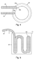
- the second magnetron includes an anode block 19 which is water-cooled by a water circuit consisting of an inlet pipe 20, and an outlet pipe which is hidden in the view of Figure 3 by the inlet pipe.
- the ceramic dome containing the antenna is not shown, and the ceramic sleeve leading to the HT supply terminals, generally referred to as the sidearm, is shown schematically and denoted by the reference numeral 21.
- a non-metallic water-containing jacket indicated generally by the reference numeral 22 is arranged between the inlet pipe 20 and the sidearm 21.
- the water-containing jacket 22 contains a cooling circuit, the inlet to which is from pipe 23, and the outlet from pipe 24. These pipes are tapped from the respective anode cooling inlet and outlet pipes.
- the diameter of the pipes leading to and from the water jacket is much narrower than those leading to and from the anode cooling circuit. Hence, the incoming water flow has a low impedance path to the anode cooling circuit, and a high impedance cooling path to the cooling circuit in the radiation absorbing jacket 22. Only a relatively small amount of cooling of the absorber is needed, and the main flow is to the anode block.
- the water jacket 22 has outer 22a and inner 22b walls, containing water.
- the high impedance cooling circuit 22c is undulating in form and shaped in a cylindrical configuration, so it can be a push-fit in the space between the inner and outer walls 22a, 22b.
- the space is filled with water and sealed with an annulus 22d at the top.
Landscapes
- Microwave Tubes (AREA)
Applications Claiming Priority (2)
| Application Number | Priority Date | Filing Date | Title |
|---|---|---|---|
| GBGB1101062.6A GB201101062D0 (en) | 2011-01-21 | 2011-01-21 | Electron tube |
| PCT/GB2012/050099 WO2012098391A1 (en) | 2011-01-21 | 2012-01-18 | Electron tube |
Publications (2)
| Publication Number | Publication Date |
|---|---|
| EP2666179A1 EP2666179A1 (en) | 2013-11-27 |
| EP2666179B1 true EP2666179B1 (en) | 2014-10-08 |
Family
ID=43769412
Family Applications (1)
| Application Number | Title | Priority Date | Filing Date |
|---|---|---|---|
| EP12702064.2A Not-in-force EP2666179B1 (en) | 2011-01-21 | 2012-01-18 | Magnetron |
Country Status (7)
| Country | Link |
|---|---|
| US (1) | US9236214B2 (ja) |
| EP (1) | EP2666179B1 (ja) |
| JP (1) | JP6182459B2 (ja) |
| CN (1) | CN103430274B (ja) |
| AU (1) | AU2012208363B2 (ja) |
| GB (2) | GB201101062D0 (ja) |
| WO (1) | WO2012098391A1 (ja) |
Families Citing this family (1)
| Publication number | Priority date | Publication date | Assignee | Title |
|---|---|---|---|---|
| US10439291B2 (en) | 2017-04-04 | 2019-10-08 | The Johns Hopkins University | Radio frequency surface wave attenuator structures and associated methods |
Family Cites Families (18)
| Publication number | Priority date | Publication date | Assignee | Title |
|---|---|---|---|---|
| JPS61284031A (ja) * | 1985-06-10 | 1986-12-15 | Nec Corp | クライストロン |
| EP0438738B1 (de) | 1990-01-15 | 1994-07-13 | Asea Brown Boveri Ag | Quasi-optische Komponente für Mikrowellenstrahlung |
| GB9118593D0 (en) | 1991-08-30 | 1991-10-16 | Eev Ltd | Magnetron |
| US6440390B2 (en) | 1992-06-05 | 2002-08-27 | Commonwealth Scientific And Industrial Research Organisation | Formulations containing a phosphide for use in the controlled generation of phosphine |
| US5469024A (en) | 1994-01-21 | 1995-11-21 | Litton Systems, Inc. | Leaky wall filter for use in extended interaction klystron |
| JPH08102263A (ja) * | 1994-08-05 | 1996-04-16 | Japan Atom Energy Res Inst | ジャイロトロン装置 |
| JPH1140068A (ja) * | 1997-07-22 | 1999-02-12 | Toshiba Corp | 加速器用マグネトロン |
| JP2000156171A (ja) * | 1998-11-18 | 2000-06-06 | Matsushita Electronics Industry Corp | マグネトロン装置およびその製造方法 |
| GB2372147A (en) | 2001-02-13 | 2002-08-14 | Marconi Applied Techn Ltd | Magnetron with radiation absorbing dielectric resonator |
| US20050230387A1 (en) * | 2004-04-14 | 2005-10-20 | Michael Regan | Insulated RF suppressor for industrial magnetrons |
| CN100485855C (zh) | 2004-12-28 | 2009-05-06 | 佛山市美的日用家电集团有限公司 | 用于磁控管的散热水套及其制备方法 |
| CN2791869Y (zh) * | 2005-02-23 | 2006-06-28 | 佛山市美的日用家电集团有限公司 | 一种水冷式磁控管 |
| US20070095823A1 (en) * | 2005-10-27 | 2007-05-03 | Sedlmayr Steven R | Microwave nucleon-electron-bonding spin alignment and alteration of materials |
| KR100700554B1 (ko) * | 2005-12-30 | 2007-03-28 | 엘지전자 주식회사 | 마그네트론 |
| JP5201711B2 (ja) * | 2007-08-08 | 2013-06-05 | パナソニック株式会社 | マグネトロン |
| US8264150B2 (en) * | 2009-07-17 | 2012-09-11 | Fusion Uv Systems, Inc. | Modular magnetron |
| CN201478250U (zh) * | 2009-08-25 | 2010-05-19 | 美的集团有限公司 | 一种磁控管 |
| GB2478990A (en) * | 2010-03-26 | 2011-09-28 | E2V Tech | Magnetron with high gfrequency cathode heater power supply |
-
2011
- 2011-01-21 GB GBGB1101062.6A patent/GB201101062D0/en not_active Ceased
-
2012
- 2012-01-18 WO PCT/GB2012/050099 patent/WO2012098391A1/en active Application Filing
- 2012-01-18 CN CN201280013253.1A patent/CN103430274B/zh not_active Expired - Fee Related
- 2012-01-18 AU AU2012208363A patent/AU2012208363B2/en not_active Ceased
- 2012-01-18 GB GB1314918.2A patent/GB2502018A/en not_active Withdrawn
- 2012-01-18 EP EP12702064.2A patent/EP2666179B1/en not_active Not-in-force
- 2012-01-18 JP JP2013549883A patent/JP6182459B2/ja not_active Expired - Fee Related
- 2012-01-18 US US13/980,260 patent/US9236214B2/en not_active Expired - Fee Related
Also Published As
| Publication number | Publication date |
|---|---|
| CN103430274B (zh) | 2017-04-12 |
| US20140021859A1 (en) | 2014-01-23 |
| JP2014506712A (ja) | 2014-03-17 |
| AU2012208363B2 (en) | 2016-04-21 |
| GB2502018A (en) | 2013-11-13 |
| GB201101062D0 (en) | 2011-03-09 |
| WO2012098391A1 (en) | 2012-07-26 |
| EP2666179A1 (en) | 2013-11-27 |
| US9236214B2 (en) | 2016-01-12 |
| CN103430274A (zh) | 2013-12-04 |
| JP6182459B2 (ja) | 2017-08-16 |
| GB201314918D0 (en) | 2013-10-02 |
Similar Documents
| Publication | Publication Date | Title |
|---|---|---|
| JP4670027B2 (ja) | マグネトロン | |
| US11011339B2 (en) | Magnetron | |
| US9697977B2 (en) | Magnetron and high-frequency heating apparatus having the same | |
| US6917022B2 (en) | Continuous flow microwave heater | |
| EP2666179B1 (en) | Magnetron | |
| AU2012208363A1 (en) | Electron tube | |
| US3748513A (en) | High frequency beam tube having an r.f. shielded and insulated collector | |
| WO1997005756A1 (en) | Liquid heating in interaction region of microwave generator | |
| CN106099326B (zh) | 一种基于等离子体介质调制的磁偶极子天线 | |
| KR100765948B1 (ko) | 마그네트론의 냉각장치 | |
| GB2325780A (en) | A choke for a magnetron of a microwave oven | |
| JP2011070867A (ja) | 電子レンジおよび電子レンジ用マグネトロン | |
| KR0139343Y1 (ko) | 마그네트론의 음극부구조 | |
| CN112786409A (zh) | 一种磁控管滤波组件、磁控管以及家用电器 | |
| KR102279747B1 (ko) | 용액 증류 시스템 | |
| JP2015049943A (ja) | マイクロ波加熱装置 | |
| KR100451235B1 (ko) | 마그네트론의 입력부 차폐구조 | |
| CN112786408A (zh) | 磁控管滤波组件、磁控管以及家用电器 | |
| CN108278641A (zh) | 一种半导体微波发生器连接结构 | |
| JP2014067615A (ja) | マグネトロン | |
| JP2001230067A (ja) | マグネトロン入力部における不要放射波漏洩抑制装置 | |
| KR100446973B1 (ko) | 마그네트론의 출력부 구조 | |
| KR970011499B1 (ko) | 변형된 노이즈필터 및 필터박스를 갖는 마그네트론 | |
| CN104253009A (zh) | 微波炉用磁控管的天线固定结构 | |
| JP2006127767A (ja) | マイクロ波発振素子 |
Legal Events
| Date | Code | Title | Description |
|---|---|---|---|
| PUAI | Public reference made under article 153(3) epc to a published international application that has entered the european phase |
Free format text: ORIGINAL CODE: 0009012 |
|
| 17P | Request for examination filed |
Effective date: 20130821 |
|
| AK | Designated contracting states |
Kind code of ref document: A1 Designated state(s): AL AT BE BG CH CY CZ DE DK EE ES FI FR GB GR HR HU IE IS IT LI LT LU LV MC MK MT NL NO PL PT RO RS SE SI SK SM TR |
|
| DAX | Request for extension of the european patent (deleted) | ||
| GRAP | Despatch of communication of intention to grant a patent |
Free format text: ORIGINAL CODE: EPIDOSNIGR1 |
|
| INTG | Intention to grant announced |
Effective date: 20140602 |
|
| GRAS | Grant fee paid |
Free format text: ORIGINAL CODE: EPIDOSNIGR3 |
|
| GRAA | (expected) grant |
Free format text: ORIGINAL CODE: 0009210 |
|
| AK | Designated contracting states |
Kind code of ref document: B1 Designated state(s): AL AT BE BG CH CY CZ DE DK EE ES FI FR GB GR HR HU IE IS IT LI LT LU LV MC MK MT NL NO PL PT RO RS SE SI SK SM TR |
|
| REG | Reference to a national code |
Ref country code: GB Ref legal event code: FG4D |
|
| REG | Reference to a national code |
Ref country code: AT Ref legal event code: REF Ref document number: 691019 Country of ref document: AT Kind code of ref document: T Effective date: 20141015 Ref country code: CH Ref legal event code: EP |
|
| REG | Reference to a national code |
Ref country code: IE Ref legal event code: FG4D |
|
| REG | Reference to a national code |
Ref country code: DE Ref legal event code: R096 Ref document number: 602012003349 Country of ref document: DE Effective date: 20141120 |
|
| REG | Reference to a national code |
Ref country code: NL Ref legal event code: VDEP Effective date: 20141008 |
|
| REG | Reference to a national code |
Ref country code: AT Ref legal event code: MK05 Ref document number: 691019 Country of ref document: AT Kind code of ref document: T Effective date: 20141008 |
|
| REG | Reference to a national code |
Ref country code: LT Ref legal event code: MG4D |
|
| PG25 | Lapsed in a contracting state [announced via postgrant information from national office to epo] |
Ref country code: NL Free format text: LAPSE BECAUSE OF FAILURE TO SUBMIT A TRANSLATION OF THE DESCRIPTION OR TO PAY THE FEE WITHIN THE PRESCRIBED TIME-LIMIT Effective date: 20141008 |
|
| PG25 | Lapsed in a contracting state [announced via postgrant information from national office to epo] |
Ref country code: ES Free format text: LAPSE BECAUSE OF FAILURE TO SUBMIT A TRANSLATION OF THE DESCRIPTION OR TO PAY THE FEE WITHIN THE PRESCRIBED TIME-LIMIT Effective date: 20141008 Ref country code: IS Free format text: LAPSE BECAUSE OF FAILURE TO SUBMIT A TRANSLATION OF THE DESCRIPTION OR TO PAY THE FEE WITHIN THE PRESCRIBED TIME-LIMIT Effective date: 20150208 Ref country code: LT Free format text: LAPSE BECAUSE OF FAILURE TO SUBMIT A TRANSLATION OF THE DESCRIPTION OR TO PAY THE FEE WITHIN THE PRESCRIBED TIME-LIMIT Effective date: 20141008 Ref country code: FI Free format text: LAPSE BECAUSE OF FAILURE TO SUBMIT A TRANSLATION OF THE DESCRIPTION OR TO PAY THE FEE WITHIN THE PRESCRIBED TIME-LIMIT Effective date: 20141008 Ref country code: NO Free format text: LAPSE BECAUSE OF FAILURE TO SUBMIT A TRANSLATION OF THE DESCRIPTION OR TO PAY THE FEE WITHIN THE PRESCRIBED TIME-LIMIT Effective date: 20150108 Ref country code: PT Free format text: LAPSE BECAUSE OF FAILURE TO SUBMIT A TRANSLATION OF THE DESCRIPTION OR TO PAY THE FEE WITHIN THE PRESCRIBED TIME-LIMIT Effective date: 20150209 |
|
| PG25 | Lapsed in a contracting state [announced via postgrant information from national office to epo] |
Ref country code: GR Free format text: LAPSE BECAUSE OF FAILURE TO SUBMIT A TRANSLATION OF THE DESCRIPTION OR TO PAY THE FEE WITHIN THE PRESCRIBED TIME-LIMIT Effective date: 20150109 Ref country code: CY Free format text: LAPSE BECAUSE OF FAILURE TO SUBMIT A TRANSLATION OF THE DESCRIPTION OR TO PAY THE FEE WITHIN THE PRESCRIBED TIME-LIMIT Effective date: 20141008 Ref country code: HR Free format text: LAPSE BECAUSE OF FAILURE TO SUBMIT A TRANSLATION OF THE DESCRIPTION OR TO PAY THE FEE WITHIN THE PRESCRIBED TIME-LIMIT Effective date: 20141008 Ref country code: SE Free format text: LAPSE BECAUSE OF FAILURE TO SUBMIT A TRANSLATION OF THE DESCRIPTION OR TO PAY THE FEE WITHIN THE PRESCRIBED TIME-LIMIT Effective date: 20141008 Ref country code: LV Free format text: LAPSE BECAUSE OF FAILURE TO SUBMIT A TRANSLATION OF THE DESCRIPTION OR TO PAY THE FEE WITHIN THE PRESCRIBED TIME-LIMIT Effective date: 20141008 Ref country code: RS Free format text: LAPSE BECAUSE OF FAILURE TO SUBMIT A TRANSLATION OF THE DESCRIPTION OR TO PAY THE FEE WITHIN THE PRESCRIBED TIME-LIMIT Effective date: 20141008 Ref country code: PL Free format text: LAPSE BECAUSE OF FAILURE TO SUBMIT A TRANSLATION OF THE DESCRIPTION OR TO PAY THE FEE WITHIN THE PRESCRIBED TIME-LIMIT Effective date: 20141008 Ref country code: AT Free format text: LAPSE BECAUSE OF FAILURE TO SUBMIT A TRANSLATION OF THE DESCRIPTION OR TO PAY THE FEE WITHIN THE PRESCRIBED TIME-LIMIT Effective date: 20141008 |
|
| PG25 | Lapsed in a contracting state [announced via postgrant information from national office to epo] |
Ref country code: BE Free format text: LAPSE BECAUSE OF NON-PAYMENT OF DUE FEES Effective date: 20150131 |
|
| REG | Reference to a national code |
Ref country code: DE Ref legal event code: R097 Ref document number: 602012003349 Country of ref document: DE |
|
| PG25 | Lapsed in a contracting state [announced via postgrant information from national office to epo] |
Ref country code: DK Free format text: LAPSE BECAUSE OF FAILURE TO SUBMIT A TRANSLATION OF THE DESCRIPTION OR TO PAY THE FEE WITHIN THE PRESCRIBED TIME-LIMIT Effective date: 20141008 Ref country code: RO Free format text: LAPSE BECAUSE OF FAILURE TO SUBMIT A TRANSLATION OF THE DESCRIPTION OR TO PAY THE FEE WITHIN THE PRESCRIBED TIME-LIMIT Effective date: 20141008 Ref country code: SK Free format text: LAPSE BECAUSE OF FAILURE TO SUBMIT A TRANSLATION OF THE DESCRIPTION OR TO PAY THE FEE WITHIN THE PRESCRIBED TIME-LIMIT Effective date: 20141008 Ref country code: EE Free format text: LAPSE BECAUSE OF FAILURE TO SUBMIT A TRANSLATION OF THE DESCRIPTION OR TO PAY THE FEE WITHIN THE PRESCRIBED TIME-LIMIT Effective date: 20141008 Ref country code: CZ Free format text: LAPSE BECAUSE OF FAILURE TO SUBMIT A TRANSLATION OF THE DESCRIPTION OR TO PAY THE FEE WITHIN THE PRESCRIBED TIME-LIMIT Effective date: 20141008 |
|
| PLBE | No opposition filed within time limit |
Free format text: ORIGINAL CODE: 0009261 |
|
| STAA | Information on the status of an ep patent application or granted ep patent |
Free format text: STATUS: NO OPPOSITION FILED WITHIN TIME LIMIT |
|
| REG | Reference to a national code |
Ref country code: CH Ref legal event code: PL |
|
| PG25 | Lapsed in a contracting state [announced via postgrant information from national office to epo] |
Ref country code: LU Free format text: LAPSE BECAUSE OF FAILURE TO SUBMIT A TRANSLATION OF THE DESCRIPTION OR TO PAY THE FEE WITHIN THE PRESCRIBED TIME-LIMIT Effective date: 20150118 |
|
| 26N | No opposition filed |
Effective date: 20150709 |
|
| PG25 | Lapsed in a contracting state [announced via postgrant information from national office to epo] |
Ref country code: MC Free format text: LAPSE BECAUSE OF FAILURE TO SUBMIT A TRANSLATION OF THE DESCRIPTION OR TO PAY THE FEE WITHIN THE PRESCRIBED TIME-LIMIT Effective date: 20141008 |
|
| PG25 | Lapsed in a contracting state [announced via postgrant information from national office to epo] |
Ref country code: LI Free format text: LAPSE BECAUSE OF NON-PAYMENT OF DUE FEES Effective date: 20150131 Ref country code: CH Free format text: LAPSE BECAUSE OF NON-PAYMENT OF DUE FEES Effective date: 20150131 |
|
| REG | Reference to a national code |
Ref country code: IE Ref legal event code: MM4A |
|
| REG | Reference to a national code |
Ref country code: FR Ref legal event code: PLFP Year of fee payment: 5 |
|
| PG25 | Lapsed in a contracting state [announced via postgrant information from national office to epo] |
Ref country code: IE Free format text: LAPSE BECAUSE OF NON-PAYMENT OF DUE FEES Effective date: 20150118 |
|
| PG25 | Lapsed in a contracting state [announced via postgrant information from national office to epo] |
Ref country code: SI Free format text: LAPSE BECAUSE OF FAILURE TO SUBMIT A TRANSLATION OF THE DESCRIPTION OR TO PAY THE FEE WITHIN THE PRESCRIBED TIME-LIMIT Effective date: 20141008 |
|
| REG | Reference to a national code |
Ref country code: FR Ref legal event code: PLFP Year of fee payment: 6 |
|
| PG25 | Lapsed in a contracting state [announced via postgrant information from national office to epo] |
Ref country code: MT Free format text: LAPSE BECAUSE OF FAILURE TO SUBMIT A TRANSLATION OF THE DESCRIPTION OR TO PAY THE FEE WITHIN THE PRESCRIBED TIME-LIMIT Effective date: 20141008 |
|
| PG25 | Lapsed in a contracting state [announced via postgrant information from national office to epo] |
Ref country code: SM Free format text: LAPSE BECAUSE OF FAILURE TO SUBMIT A TRANSLATION OF THE DESCRIPTION OR TO PAY THE FEE WITHIN THE PRESCRIBED TIME-LIMIT Effective date: 20141008 Ref country code: HU Free format text: LAPSE BECAUSE OF FAILURE TO SUBMIT A TRANSLATION OF THE DESCRIPTION OR TO PAY THE FEE WITHIN THE PRESCRIBED TIME-LIMIT; INVALID AB INITIO Effective date: 20120118 Ref country code: BG Free format text: LAPSE BECAUSE OF FAILURE TO SUBMIT A TRANSLATION OF THE DESCRIPTION OR TO PAY THE FEE WITHIN THE PRESCRIBED TIME-LIMIT Effective date: 20141008 |
|
| PG25 | Lapsed in a contracting state [announced via postgrant information from national office to epo] |
Ref country code: TR Free format text: LAPSE BECAUSE OF FAILURE TO SUBMIT A TRANSLATION OF THE DESCRIPTION OR TO PAY THE FEE WITHIN THE PRESCRIBED TIME-LIMIT Effective date: 20141008 |
|
| REG | Reference to a national code |
Ref country code: FR Ref legal event code: PLFP Year of fee payment: 7 |
|
| REG | Reference to a national code |
Ref country code: DE Ref legal event code: R082 Ref document number: 602012003349 Country of ref document: DE Representative=s name: PATENTANWALTSKANZLEI MEYER, DE Ref country code: DE Ref legal event code: R081 Ref document number: 602012003349 Country of ref document: DE Owner name: TELEDYNE UK LTD., CHELMSFORD, GB Free format text: FORMER OWNER: E2V TECHNOLOGIES (UK) LTD., CHELMSFORD, ESSEX, GB Ref country code: DE Ref legal event code: R081 Ref document number: 602012003349 Country of ref document: DE Owner name: TELEDYNE E2V (UK) LTD., CHELMSFORD, GB Free format text: FORMER OWNER: E2V TECHNOLOGIES (UK) LTD., CHELMSFORD, ESSEX, GB |
|
| REG | Reference to a national code |
Ref country code: FR Ref legal event code: CD Owner name: TELEDYNE E2V (UK) LIMITED, GB Effective date: 20180410 |
|
| PG25 | Lapsed in a contracting state [announced via postgrant information from national office to epo] |
Ref country code: MK Free format text: LAPSE BECAUSE OF FAILURE TO SUBMIT A TRANSLATION OF THE DESCRIPTION OR TO PAY THE FEE WITHIN THE PRESCRIBED TIME-LIMIT Effective date: 20141008 |
|
| PG25 | Lapsed in a contracting state [announced via postgrant information from national office to epo] |
Ref country code: AL Free format text: LAPSE BECAUSE OF FAILURE TO SUBMIT A TRANSLATION OF THE DESCRIPTION OR TO PAY THE FEE WITHIN THE PRESCRIBED TIME-LIMIT Effective date: 20141008 |
|
| REG | Reference to a national code |
Ref country code: DE Ref legal event code: R082 Ref document number: 602012003349 Country of ref document: DE Representative=s name: PATENTANWALTSKANZLEI MEYER, DE Ref country code: DE Ref legal event code: R081 Ref document number: 602012003349 Country of ref document: DE Owner name: TELEDYNE UK LTD., CHELMSFORD, GB Free format text: FORMER OWNER: TELEDYNE E2V (UK) LTD., CHELMSFORD, ESSEX, GB |
|
| PGFP | Annual fee paid to national office [announced via postgrant information from national office to epo] |
Ref country code: IT Payment date: 20200123 Year of fee payment: 9 Ref country code: GB Payment date: 20200127 Year of fee payment: 9 Ref country code: DE Payment date: 20200129 Year of fee payment: 9 |
|
| PGFP | Annual fee paid to national office [announced via postgrant information from national office to epo] |
Ref country code: FR Payment date: 20200127 Year of fee payment: 9 |
|
| REG | Reference to a national code |
Ref country code: DE Ref legal event code: R119 Ref document number: 602012003349 Country of ref document: DE |
|
| GBPC | Gb: european patent ceased through non-payment of renewal fee |
Effective date: 20210118 |
|
| PG25 | Lapsed in a contracting state [announced via postgrant information from national office to epo] |
Ref country code: FR Free format text: LAPSE BECAUSE OF NON-PAYMENT OF DUE FEES Effective date: 20210131 |
|
| PG25 | Lapsed in a contracting state [announced via postgrant information from national office to epo] |
Ref country code: GB Free format text: LAPSE BECAUSE OF NON-PAYMENT OF DUE FEES Effective date: 20210118 Ref country code: DE Free format text: LAPSE BECAUSE OF NON-PAYMENT OF DUE FEES Effective date: 20210803 |
|
| PG25 | Lapsed in a contracting state [announced via postgrant information from national office to epo] |
Ref country code: IT Free format text: LAPSE BECAUSE OF NON-PAYMENT OF DUE FEES Effective date: 20210118 |