EP2664518A2 - Lenksystem - Google Patents
Lenksystem Download PDFInfo
- Publication number
- EP2664518A2 EP2664518A2 EP13167590.2A EP13167590A EP2664518A2 EP 2664518 A2 EP2664518 A2 EP 2664518A2 EP 13167590 A EP13167590 A EP 13167590A EP 2664518 A2 EP2664518 A2 EP 2664518A2
- Authority
- EP
- European Patent Office
- Prior art keywords
- drainage
- case
- valve body
- outlet port
- steering system
- Prior art date
- Legal status (The legal status is an assumption and is not a legal conclusion. Google has not performed a legal analysis and makes no representation as to the accuracy of the status listed.)
- Granted
Links
- 239000011347 resin Substances 0.000 claims abstract description 29
- 229920005989 resin Polymers 0.000 claims abstract description 29
- 238000004891 communication Methods 0.000 claims abstract description 13
- 230000005540 biological transmission Effects 0.000 claims description 18
- 239000003638 chemical reducing agent Substances 0.000 claims description 13
- XLYOFNOQVPJJNP-UHFFFAOYSA-N water Substances O XLYOFNOQVPJJNP-UHFFFAOYSA-N 0.000 description 73
- 239000000463 material Substances 0.000 description 31
- 238000000034 method Methods 0.000 description 12
- 230000002093 peripheral effect Effects 0.000 description 12
- 230000008569 process Effects 0.000 description 12
- 238000007711 solidification Methods 0.000 description 10
- 230000008023 solidification Effects 0.000 description 10
- 230000000694 effects Effects 0.000 description 8
- 239000007769 metal material Substances 0.000 description 7
- 238000003780 insertion Methods 0.000 description 6
- 230000037431 insertion Effects 0.000 description 6
- 230000008014 freezing Effects 0.000 description 5
- 238000007710 freezing Methods 0.000 description 5
- 230000015572 biosynthetic process Effects 0.000 description 4
- 230000033001 locomotion Effects 0.000 description 4
- 230000007246 mechanism Effects 0.000 description 3
- 238000007789 sealing Methods 0.000 description 3
- 230000007797 corrosion Effects 0.000 description 2
- 238000005260 corrosion Methods 0.000 description 2
- 230000003247 decreasing effect Effects 0.000 description 2
- 230000007935 neutral effect Effects 0.000 description 2
- 230000008859 change Effects 0.000 description 1
- 230000000052 comparative effect Effects 0.000 description 1
- 230000006866 deterioration Effects 0.000 description 1
- 230000009977 dual effect Effects 0.000 description 1
- 230000009467 reduction Effects 0.000 description 1
- 230000004044 response Effects 0.000 description 1
Images


Classifications
-
- F—MECHANICAL ENGINEERING; LIGHTING; HEATING; WEAPONS; BLASTING
- F16—ENGINEERING ELEMENTS AND UNITS; GENERAL MEASURES FOR PRODUCING AND MAINTAINING EFFECTIVE FUNCTIONING OF MACHINES OR INSTALLATIONS; THERMAL INSULATION IN GENERAL
- F16K—VALVES; TAPS; COCKS; ACTUATING-FLOATS; DEVICES FOR VENTING OR AERATING
- F16K27/00—Construction of housing; Use of materials therefor
-
- B—PERFORMING OPERATIONS; TRANSPORTING
- B62—LAND VEHICLES FOR TRAVELLING OTHERWISE THAN ON RAILS
- B62D—MOTOR VEHICLES; TRAILERS
- B62D5/00—Power-assisted or power-driven steering
- B62D5/04—Power-assisted or power-driven steering electrical, e.g. using an electric servo-motor connected to, or forming part of, the steering gear
- B62D5/0421—Electric motor acting on or near steering gear
- B62D5/0424—Electric motor acting on or near steering gear the axes of motor and final driven element of steering gear, e.g. rack, being parallel
-
- B—PERFORMING OPERATIONS; TRANSPORTING
- B62—LAND VEHICLES FOR TRAVELLING OTHERWISE THAN ON RAILS
- B62D—MOTOR VEHICLES; TRAILERS
- B62D5/00—Power-assisted or power-driven steering
- B62D5/04—Power-assisted or power-driven steering electrical, e.g. using an electric servo-motor connected to, or forming part of, the steering gear
- B62D5/0442—Conversion of rotational into longitudinal movement
- B62D5/0445—Screw drives
- B62D5/0448—Ball nuts
-
- F—MECHANICAL ENGINEERING; LIGHTING; HEATING; WEAPONS; BLASTING
- F16—ENGINEERING ELEMENTS AND UNITS; GENERAL MEASURES FOR PRODUCING AND MAINTAINING EFFECTIVE FUNCTIONING OF MACHINES OR INSTALLATIONS; THERMAL INSULATION IN GENERAL
- F16K—VALVES; TAPS; COCKS; ACTUATING-FLOATS; DEVICES FOR VENTING OR AERATING
- F16K15/00—Check valves
- F16K15/14—Check valves with flexible valve members
- F16K15/148—Check valves with flexible valve members the closure elements being fixed in their centre
-
- Y—GENERAL TAGGING OF NEW TECHNOLOGICAL DEVELOPMENTS; GENERAL TAGGING OF CROSS-SECTIONAL TECHNOLOGIES SPANNING OVER SEVERAL SECTIONS OF THE IPC; TECHNICAL SUBJECTS COVERED BY FORMER USPC CROSS-REFERENCE ART COLLECTIONS [XRACs] AND DIGESTS
- Y10—TECHNICAL SUBJECTS COVERED BY FORMER USPC
- Y10T—TECHNICAL SUBJECTS COVERED BY FORMER US CLASSIFICATION
- Y10T137/00—Fluid handling
- Y10T137/6851—With casing, support, protector or static constructional installations
- Y10T137/6855—Vehicle
- Y10T137/6881—Automotive
Definitions
- the invention relates to a steering system that includes a rack housing and a drainage device.
- a drainage device 200 includes a drainage case 210, a drainage valve 240, and a seal ring 250.
- the drainage case 210 has a first drainage case 220 and a second drainage case 230.
- the drainage case 210 is formed by connecting the first drainage case 220 and the second drainage case 230, which are formed as separate parts, to each other.
- the first drainage case 220 has a case inlet port 221.
- the case inlet port 221 is communicated with a housing space of a rack housing (not shown).
- the second drainage case 230 has case outlet ports 231.
- the case outlet ports 231 are communicated with the outside of the rack housing.
- the drainage valve 240 has a body portion 241 and a flange portion 242. As the flange portion 242 comes into contact with the inner face of the first drainage case 220, the flange portion 242 interrupts communication between the case inlet port 221 and the case outlet ports 231.
- water may enter the housing space from the outside of the rack housing.
- the water that has entered the housing space flows into the first drainage case 220 through the case inlet port 221 of the first drainage case 220.
- the water in the first drainage case 220 is accumulated on the flange portion 242.
- a restoring force of the flange portion 242 of the drainage valve 240 may be reduced as the flange portion 242 is deformed repeatedly. If the restoring force is significantly reduced, a gap is formed between the flange portion 242 and the inner face of the first drainage case 220 when no water is accumulated on the flange portion 242. Therefore, foreign matter may enter the housing space of the rack housing from the outside of the rack housing through the case outlet ports 231.
- the invention provides a steering system that includes a drainage device configured such that the sealing performance is less likely to deteriorate.
- a steering system including a rack housing and a drainage device, wherein the drainage device includes: a drainage case having a case inlet port communicated with a housing space of the rack housing, a case outlet port communicated with an outside of the rack housing, a drainage space communicated with the case inlet port and the case outlet port, and a case bottom face that faces the drainage space; and a drainage valve arranged in the drainage space and having a hollow shape, the drainage valve having a valve body inlet port portion communicated with the case inlet portion, and a valve body outlet port portion that is made of a resin and interrupts communication between the case inlet port and the case outlet port when the valve body outlet port portion comes into contact with the case bottom face.
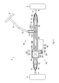
- the configuration of a steering system 1 will be described with reference to FIG. 1 .
- the steering system 1 includes a steering system body 10, a rack housing 20, an assist device 30, and a drainage device 100.
- the steering system 1 is configured as a rack-parallel type electric power steering system, in which the assist device 30 assists an operation of a steering wheel 2.
- the steering system body 10 includes a column shaft 11, an intermediate shaft 12, a pinion shaft 13, a rack shaft 14, a rack-and-pinion mechanism 15, two ball joints 16, two bellows 17, and two tie rods 18.
- the column shaft 11, the intermediate shaft 12, and the pinion shaft 13 of the steering system body 10 are rotated together with each other.
- the rack shaft 14 is moved in its longitudinal direction due to the rotation of the pinion shaft 13.
- the tie rods 18 are operated via the ball joints 16.
- the steering system body 10 changes the steered angle of steered wheels 3 via knuckles 4 by operating the tie rods 18.
- the rack shaft 14 has a gear portion 14A and a thread formation portion 14B.
- the rack shaft 14 has a plurality of rack gears 14C in a predetermined range along the central axial direction within the gear portion 14A.
- the rack shaft 14 has an external thread that serves as a rack thread 14D in a predetermined range along the central axial direction within the thread formation portion 14B.
- the rack-and-pinion mechanism 15 includes a pinion gear 13A of the pinion shaft 13, and the rack gears 14C of the rack shaft 14.
- the rack-and-pinion mechanism 15 converts the rotation of the pinion shaft 13 into a linear motion of the rack shaft 14.
- the rack housing 20 is made of a metal material.
- the rack housing 20 has a first housing 21, a second housing 22, and a housing space 23.
- the rack housing 20 is formed by connecting the first housing 21 and the second housing 22, which are formed as separate parts, to each other.
- the rack housing 20 houses the pinion shaft 13, the rack shaft 14, and the ball joints 16, in addition to a speed reducer 50, a ball screw device 60 and a support device 70 that constitute the assist device 30.
- the bellows 17 are made of an elastic resin material. Each of the bellows 17 is fitted to a corresponding one of the end portions of the rack housing 20 and a corresponding one of the tie rods 18. Each of the bellows 17 covers part of the rack shaft 14, which projects from the rack housing 20, a corresponding one of the ball joints 16, and a corresponding one of the tie rods 18. The bellows 17 suppress entry of foreign matter into the housing space 23 from the outside of the rack housing 20.
- the assist device 30 includes an electric motor 40, the speed reducer 50, the ball screw device 60, and the support device 70 (see FIG. 2 ).
- the assist device 30 as the rotation of the electric motor 40 is transmitted to the ball screw device 60 via the speed reducer 50 to rotate the ball screw device 60, a force that acts in the central axial direction of the rack shaft 14 is applied to the rack shaft 14.
- the drainage device 100 is fitted to a valve fixing portion 25 of the second housing 22.
- the drainage device 100 drains water, which has entered the housing space 23 of rack housing 20, from out of the rack housing 20.
- the electric motor 40 is fitted to the outer face of the rack housing 20.
- the electric motor 40 includes a motor body 41 and a motor shaft 42.
- the motor body 41 is fixed to the first housing 21, the position of the electric motor 40 relative to the rack housing 20 is fixed.
- the electric motor 40 rotates the ball screw device 60 via the speed reducer 50.
- the motor shaft 42 is arranged across the motor body 41 and the housing space 23 of the rack housing 20.
- the rotation central axis of the motor shaft 42 is parallel to the central axis of the rack shaft 14.
- the motor shaft 42 rotates as electric current is supplied to the motor body 41.
- the ball screw device 60 is fitted to the outer periphery of the thread formation portion 14B of the rack shaft 14.
- the ball screw device 60 rotates relative to the rack shaft 14 about the central axis of the rack shaft 14.
- the ball screw device 60 includes a nut 61, and balls 62. In the ball screw device 60, a force that acts in the central axial direction of the rack shaft 14 is applied to the rack shaft 14 by the rotation of the nut 61.
- the speed reducer 50 is arranged across the motor shaft 42 and the nut 61.
- the speed reducer 50 includes a drive pulley 51, a driven pulley 52, and a transmission belt 53.
- the drive pulley 51 is fixed to the motor shaft 42.
- the driven pulley 52 is fixed to a rotational support member 71.
- the transmission belt 53 is looped over the drive pulley 51 and the driven pulley 52.
- the speed of rotation of the drive pulley 51 is reduced by the driven pulley 52.
- the support device 70 is arranged around the thread formation portion 14B of the rack shaft 14 and the ball screw device 60.
- the support device 70 includes the rotational support member 71, a bearing 72, a radial support member 73, and two thrust support members 74.
- the support device 70 supports rotation of the nut 61 relative to the rack housing 20 and the rack shaft 14.
- the rotational support member 71 is made of a metal material.
- the rotational support member 71 has a cylindrical shape.
- the rotational support member 71 is fixed to the outer periphery of the nut 61.
- the rotational support member 71 rotates relative to the rack shaft 14 about the central axis of the rack shaft 14 as the transmission belt 53 turns.
- the bearing 72 is made of a metal material.
- An inner ring of the bearing 72 is fixed to the outer periphery of the rotational support member 71.
- the bearing 72 rotates relative to the rack shaft 14 about the central axis of the rack shaft 14.
- the radial support member 73 is made of an elastic resin material.
- the radial support member 73 has an annular shape.
- the radial support member 73 is fitted onto the outer periphery of an outer ring of the bearing 72.
- the radial support member 73 is arranged between the outer ring of the bearing 72 and the rack housing 20 while being compressed radially.
- the thrust support members 74 are made of an elastic resin material. Each of the thrust support members 74 has an annular shape. The thrust support members 74 are arranged between end faces of the outer ring of the bearing 72 and the rack housing 20 while being compressed radially.
- the second housing 22 has a housing bottom wall portion 24. At the housing bottom wall portion 24, the second housing 22 faces the drive pulley 51 and the transmission belt 53 via a gap 26.
- the assist device 30 rotates the motor shaft 42 of the electric motor 40 and the drive pulley 51 in response to the rotation of the steering wheel 2 (see FIG. 1 ).
- the drive pulley 51 rotates the driven pulley 52, the rotational support member 71, and the nut 61 via the transmission belt 53.
- the nut 61 applies a force, which acts in the central axial direction of the rack shaft 14, to the rack shaft 14 via the balls 62.
- the drainage device 100 includes a drainage case 110, a drainage valve 160, and a seal ring 190.
- the drainage device 100 is formed by connecting the drainage case 110, the drainage valve 160, and the seal ring 190, which are formed as separate parts, to each other.
- the drainage case 110 has a first drainage case 120, a second drainage case 150, and a drainage space 111.
- the drainage case 110 is formed by connecting the first drainage case 120 and the second drainage case 150, which are formed as separate parts, to each other.
- the first drainage case 120 is made of a resin material.
- the first drainage case 120 has a stepped shape.
- the first drainage case 120 is fitted to the valve fixing portion 25 of the second housing 22.
- the first drainage case 120 has a case upper portion 130 and a case lower portion 140.
- the first drainage case 120 has a configuration in which the case upper portion 130 and the case lower portion 140 are made of the same resin material and formed into a single-piece member.
- the case upper portion 130 has a cylindrical shape.
- the case upper portion 130 has an upper peripheral wall portion 131, a case inlet port 132, a case thread 133, a ring groove 134, and an upper space 135.
- the case upper portion 130 is screwed into the valve fixing portion 25 of the second housing 22, at the case thread 133 that is formed on an outer periphery 136 of the case upper portion 130.
- the upper space 135 is defined by an inner periphery 137 of the upper peripheral wall portion 131.
- the upper space 135 of the case upper portion 130 and the housing space 23 of the rack housing 20 are communicated with each other through the case inlet port 132.
- the case lower portion 140 has a hexagonal shape.
- the case lower portion 140 has a lower peripheral wall portion 141, a rib portion 142, an open portion 143, an insertion portion 144, and a lower space 145.
- the case lower portion 140 is fitted to the valve fixing portion 25 with an outer periphery 146 of the case lower portion 140 located outside the second housing 22.
- a lower space 145 is defined by an inner periphery 147 of the lower peripheral wall portion 141.
- the second drainage case 150 is made of a resin material.
- the second drainage case 150 has a hexagonal shape that corresponds to the case lower portion 140.
- the second drainage case 150 has a fitting peripheral wall portion 151, a bottom wall portion 152, a convex portion 153, a plurality of case outlet ports 154, and an inner space 155.
- the second drainage case 150 is fitted to the first drainage case 120 with an outer periphery 156 of the second drainage case 150 facing the inner periphery 147 of the case lower portion 140.
- the second drainage case 150 is fixed to the first drainage case 120 when a restricting portion 151A of the fitting peripheral wall portion 151 is press-fitted to the inner periphery 147 of the case lower portion 140.
- the inner space 155 is defined by an inner periphery 157 of the fitting peripheral wall portion 151.
- the inner space 155 of the second drainage case 150 and a space outside the rack housing 20 are communicated with each other through the case outlet ports 154.
- the convex portion 153 is shaped such that the convex portion 513 projects upward in the height direction, that is, the height of the convex portion 513 increases from the outer side toward the center of the second drainage case 150 in the radial direction.
- the convex portion 153 has a convex seal face 153A that serves as the bottom face of the case. In the convex portion 153, the convex seal face 153A is inclined gently from the center of the convex portion 153 toward the bottom wall portion 152. At the convex seal face 153A, the convex portion 153 contacts the drainage valve 160. The convex portion 153 guides water from the convex seal face 153A to each of the case outlet ports 154.
- the case outlet ports 154 pass through the bottom wall portion 152.
- the case outlet ports 154 are formed at equal intervals about the central axis of the second drainage case 150.
- Each of the case outlet ports 154 is formed at a position that is lower than the convex seal face 153A of the convex portion 153 in the height direction of the second drainage case 150.
- the drainage space 111 has the upper space 135 of the case upper portion 130, the lower space 145 of the case lower portion 140, and the inner space 155 of the second drainage case 150.
- the drainage space 111 provides communication between the case inlet port 132 and the case outlet ports 154.
- the seal ring 190 is made of an elastic resin material.
- the seal ring 190 has an annular shape.
- the seal ring 190 is fitted into the ring groove 134 of the first drainage case 120.
- the seal ring 190 provides sealing between the valve fixing portion 25 of the second housing 22 and the outer periphery 136 of the first drainage case 120.
- the drainage valve 160 is made of an elastic resin material with an elasticity higher than that of the resin material of the drainage case 110.
- the drainage valve 160 has a hollow shape.
- the drainage valve 160 is arranged in the drainage space 111.
- the drainage valve 160 is fixed to the drainage case 110.
- the drainage valve 160 has a valve body inlet port portion 170 and a valve body outlet port portion 180.
- the drainage valve 160 has a configuration in which the valve body inlet port portion 170 and the valve body outlet port portion 180 are made of the same resin material and formed into a single-piece member.
- the drainage valve 160 allows or interrupts communication between the case inlet port 132 and the case outlet ports 154 of the drainage case 110.
- the valve body inlet port portion 170 has a cylindrical shape.
- the valve body inlet port portion 170 is fitted to the insertion portion 144 of the first drainage case 120.
- the valve body inlet port portion 170 is arranged across the upper space 135 of the first drainage case 120 and the inner space 155 of the second drainage case 150.
- the valve body inlet port portion 170 has an inlet port body portion 171, an inlet port projecting portion 172, and a valve body inlet port space 173.
- the upper space 135 of the first drainage case 120 and the inner space 155 of the second drainage case 150 are communicated with each other through the valve body inlet port space 173 of the valve body inlet port portion 170.
- a portion of an outer periphery 174 of the inlet port body portion 171 is pressed against the inner periphery of the insertion portion 144 of the first drainage case 120.
- the valve body inlet port portion 170 is fixed to the first drainage case 120 by a restoring force that is generated as the inlet port body portion 171 is pressed against the inner periphery of the insertion portion 144.
- the valve body inlet port space 173 is defined by an inner periphery 175 of the inlet port body portion 171.
- the inlet port projecting portion 172 has a flange shape.
- the inlet port projecting portion 172 is arranged in the upper space 135 of the first drainage case 120.
- the inlet port projecting portion 172 has an outer diameter larger than the diameter of an opening of the insertion portion 144 of the first drainage case 120.
- the outer diameter of the inlet port projecting portion 172 is largest at the central part of the inlet port projecting portion 172 in its height direction.
- the valve body outlet port portion 180 has a tapered and hollow shape.
- the valve body outlet port portion 180 is arranged in the inner space 155 of the second drainage case 150.
- the valve body outlet port portion 180 has an outlet port contact portion 181, an outlet port intermediate portion 182, and a valve body outlet port space 183.
- the valve body outlet port portion 180 contacts the convex portion 153 with an outer periphery 184 of the valve body outlet port portion 180 facing the rib portion 142 and the insertion portion 144 of the first drainage case 120 via a space.
- the valve body outlet port space 183 is defined by the inner periphery 185 of the valve body outlet port portion 180.
- the inner periphery 185 has a valve body seal face 185A of the outlet port contact portion 181 and a valve body opposing face 185B of the outlet port intermediate portion 182.
- the valve body seal face 185A of the inner periphery 185 is pressed against the convex seal face 153A of the convex portion 153.
- the inner diameter of the outlet port contact portion 181 is larger than that of the outlet port contact portion 181 in a state where the drainage valve 160 is not fitted to the drainage case 110.
- the outlet port contact portion 181 comes into close contact with the convex seal face 153A due to a resorting force generated as the outlet port contact portion 181 is pressed against the convex seal face 153A.
- the outlet port contact portion 181 interrupts communication between the valve body outlet port space 183 and the inner space 155 of the second drainage case 150 as the outlet port contact portion 181 comes into close contact with the convex seal face 153A.
- the water that has entered the housing space 23 moves on the wall face of the first housing 21 or the second housing 22, and moves to the wall face of the housing bottom wall portion 24 of the second housing 22.
- the water flows from the wall face of the housing bottom wall portion 24 into the upper space 135 of the first drainage case 120 (the drainage space 111 of the drainage case 110) through the case inlet port 132 of the drainage case 110.
- the water flows from the upper space 135 of the first drainage case 120 into an inner space of the drainage valve 160 (the valve body inlet port space 173) through the valve body inlet port portion 170.
- the water flows from the valve body inlet port space 173 into the valve body outlet port space 183.
- the water flows from the valve body outlet port space 183 into the gap between the outlet port intermediate portion 182 of the valve body outlet port portion 180 and the convex portion 153.
- the water accumulated on the convex portion 153 in the valve body outlet port space 183 applies a pressure to the valve body outlet port portion 180.
- a pressure of water received by the outlet port contact portion 181 is smaller than a certain pressure, the valve body outlet port portion 180 stays in close contact with the convex seal face 153A of the convex portion 153.
- the valve body outlet port portion 180 interrupts communication between the valve body outlet port space 183 and the inner space 155 of the second drainage case 150. In other words, the valve body outlet port portion 180 interrupts communication between the case inlet port 132 and the case outlet ports 154 of the drainage case 110.
- valve body outlet port portion 180 when a pressure of water received by the outlet port contact portion 181 is equal to or larger than the certain pressure, the valve body outlet port portion 180 is deformed in such a direction that the outlet port contact portion 181 is separated from convex seal face 153A.
- the valve body outlet port portion 180 provides communication between the valve body outlet port space 183 and the inner space 155 of the second drainage case 150. In other words, the valve body outlet port portion 180 provides communication between the case inlet port 132 and the case outlet ports 154 of the drainage case 110.
- the water accumulated on the convex portion 153 is guided to the case outlet ports 154 by the convex seal face 153A. Then, the water that has reached the case outlet ports 154 is drained out of the drainage space 111 of the drainage case 110 through the case outlet ports 154. In this way, the drainage device 100 drains the water from the housing space 23 of the rack housing 20 to the outside of the rack housing 20.
- the steering system 1 according to the present embodiment provides the following advantageous effects.
- the drainage device 100 includes the drainage valve 160 that has a hollow shape.
- the valve body outlet port portion 180 of the drainage valve 160 which has a tapered and hollow shape, provides or interrupts communication between the case inlet port 132 and the case outlet ports 154.
- a reduction in restoring force of the drainage valve 160 due to repeated deformation is less likely to occur as compared to the conventional drainage device 200 shown in FIG. 5 and FIG. 6 , that is, the drainage device 200 in which the flange portion 242 provides or interrupts communication between the case inlet port 221 and the case outlet ports 231.
- deterioration of the sealing performance of the drainage valve 160 is suppressed.
- the drainage device 100 has a configuration in which the outlet port contact portion 181 of the valve body outlet port portion 180 is in close contact with the convex portion 153 of the second drainage case 150. With this configuration, the situation where foreign matter enters the housing space 23 from the outside of the rack housing 20 through the drainage device 100 is less likely to occur.
- the drainage device 100 has the valve body outlet port portion 180 having a tapered and hollow shape. With this configuration, the valve body outlet port portion 180 is deformed by a pressure of water more easily as compared to a configuration in which the valve body outlet port portion 180 does not have a tapered shape. Thus, the drainage performance of the drainage device 100 is improved. Even if a dimensional tolerance is increased, the valve body outlet port portion 180 reliably comes into close contact with the second drainage case 150 as compared to the configuration where the valve body outlet port portion 180 does not have a tapered shape. Therefore, the dimensional management of the drainage valve 160 is facilitated.
- the drainage device 100 has the convex portion 153. With the configuration, the water accumulated in the valve body outlet port space 183 (on the inner side of the drainage valve 160) easily flows toward the case outlet ports 154. Therefore, the drainage performance of the drainage device 100 is improved.
- the drainage device 100 is fixed to the rack housing 20 at the case thread 133 of the drainage case 110. With this configuration, the drainage case 110 is fitted to the rack housing 20 easily.
- the drainage device 100 has the seal ring 190. With this configuration, a gap between the drainage case 110 and the rack housing 20 is sealed by the seal ring 190. Thus, entry of the water into the housing space 23 through the gap between the drainage case 110 and the rack housing 20 is suppressed.
- the water that has entered the housing space 23 of the rack housing 20 may be solidified in the housing space 23. Solidification of the water occurs through, for example, a first process, a second process, a third process, or a fourth process.
- the water in the housing space 23 is solidified due to a decrease in the ambient temperature.
- solidification of the water is more likely to occur if the frequency of operation of the steering wheel 2 after the entry of the water into the housing space 23 is lower.
- the water in the housing space 23 is solidified.
- the water in the housing space 23 is solidified due to a decrease in the ambient temperature.
- solidification of the water is more likely to occur if the frequency of operation of the steering wheel 2 after the entry of the water into the housing space 23 is lower.
- the water in the housing space 23 is solidified.
- the water in the housing space 23 is solidified due to a decrease in the ambient temperature.
- solidification of water is more likely to occur if the vehicle stopping time after the entry of the water into the housing space 23 is longer.
- the transmission belt 53 of the speed reducer 50 may be frozen as the water is solidified.
- the rotation of the nut 61 is restricted by the transmission belt 53, and the movement of the rack shaft 14 is thus restricted.
- the rack shaft 14 does not move. Accordingly, the steered angle of the steered wheels 3 does not change. Hence, a larger steering torque is input into the steering wheel 2.
- the transmission belt 53 may be broken due to the torque that acts on the nut 61 via the rack shaft 14.
- the transmission belt 53 is broken, the movement of the rack shaft 14 is no longer restricted by the nut 61, and the movement of the rack shaft 14 in accordance with an operation of the steering wheel 2 is permitted.
- the electric motor 40 stops assisting the operation of the steering wheel 2.
- operation failures of the steering system body 10 and the assist device 30 may occur due to solidification of the water in the housing space 23 while the vehicle is travelling or stopped.
- the steering system 1 has the drainage device 100, the water that has entered the housing space 23 is drained. Therefore, solidification of the water in the housing space 23, and freezing of the transmission belt 53 due to the solidification of water are less likely to occur. Hence, as compared to the virtual steering system, operation failures of the steering system body 10 and the assist device 30 are less likely to occur while the vehicle is travelling.
- the invention includes embodiments other than the foregoing embodiment. Modified examples of the foregoing embodiment will be described below as other embodiments of the invention. The modified examples described below may be combined with each other.
- the drainage valve 160 in the above-described embodiment has a configuration in which the valve body inlet port portion 170 and the valve body outlet port portion 180 are made of the same resin material and formed into a single-piece member.
- the drainage valve 160 in a modified example has any one of the configurations (a) to (c) below.
- the drainage valve 160 in the modified example has a configuration in which the valve body inlet port portion 170 and the valve body outlet port portion 180, which are formed as separate parts, are connected to each other.
- the drainage valve 160 in the modified example has the valve body inlet port portion 170 and the valve body outlet port portion 180 that are made of the same resin material.
- the drainage valve 160 in the modified example (b) has the same configuration as that of the drainage valve 160 in the modified example (a) except that the valve body inlet port portion 170 and the valve body outlet port portion 180 are made of resin materials different from each other.
- the valve body outlet port portion 180 is made of an elastic resin material having an elasticity higher than that of a material of the valve body inlet port portion 170.
- the drainage valve 160 in the modified example (c) has the same configuration as that of the drainage valve 160 in the modified example (a) except that the valve body inlet port portion 170 is made of a material other than a resin material (for example, a metal material) and the valve body outlet port portion 180 is made of an elastic resin material.
- a resin material for example, a metal material
- the drainage valve 160 in the modified example (d) has the same configuration as that of any one of the foregoing modified examples (a) to (c) except that the valve body inlet port portion 170 is formed by connecting a plurality of parts, which are formed as separate parts, to each other.
- the drainage valve 160 in the modified example (e) has the same configuration as that of any one of the foregoing modified examples (a) to (d) except that the valve body outlet port portion 180 is formed by connecting a plurality of parts, which are formed as separate parts, to each other.
- the drainage device 100 has a configuration in which the drainage case 110 is fixed to the rack housing 20 when the case thread 133 of the case upper portion 130 is screwed to the valve fixing portion 25.
- the drainage device 100 in a modified example has a configuration described in (a) or (b) below.
- the drainage device 100 in the modified example (a) has a configuration in which a drainage case 110 is fixed to the rack housing 20 when the case upper portion 130 is press-fitted to the valve fixing portion 25.
- the case thread 133 of the case upper portion 130 is omitted.
- the drainage device 100 in the modified example (b) has a bolt fastening portion at the drainage case 110, and the case thread 133 of the case upper portion 130 is omitted.
- the drainage device 100 in this modified example is fixed to the housing bottom wall portion 24 by a bolt that is screwed across the bolt fastening portion and the housing bottom wall portion 24.
- the drainage device 100 in the above-described embodiment has a configuration in which the case upper portion 130 is arranged on the inner side of the housing bottom wall portion 24, and the case lower portion 140 is arranged outside the rack housing 20.
- the drainage device 100 in a modified example has any one of the configurations described in (a) to (d) below.
- the drainage device 100 in the modified example (a) has a configuration in which the case upper portion 130 and the case lower portion 140 are arranged on the inner side of the housing bottom wall portion 24.
- the drainage device 100 in this modified example has the case lower portion 140 having a cylindrical shape.
- the drainage device 100 in the modified example (b) has the same configuration as that of the drainage device 100 in the modified example (a) except that the drainage device 100 in the modified example (b) has an external thread at the outer periphery 146 of the case lower portion 140 instead of, or in addition to the case thread 133 of the case upper portion 130.
- the drainage device 100 in the modified example (c) has the same configuration as that of the drainage device 100 in the modified example (a) except that the drainage device 100 in the modified example (c) has a configuration in which the case upper portion 130 and the case lower portion 140 are press-fitted to the housing bottom wall portion 24. In the drainage device 100 in this modified example, threads of the case upper portion 130 and the case lower portion 140 are omitted.
- the drainage device 100 in the modified example (d) has the same configuration as that of any one of the modified examples (a) to (c) except that the drainage device 100 in the modified example (d) has a configuration in which the case upper portion 130 projects into the housing space 23 from the housing bottom wall portion 24.
- the drainage device 100 in the modified example (e) has the same configuration as that of the modified example (d) except that the drainage device 100 in the modified example (e) has a hole that is formed in a portion of the case upper portion 130, which is located at the housing space 23, and that passes through the upper peripheral wall portion 131. With this configuration, the water on the wall face of the housing bottom wall portion 24 easily flows into the upper space 135 of the case upper portion 130.
- the drainage device 100 in the above-described embodiment has the case lower portion 140 having a hexagonal shape.
- the drainage device 100 in a modified example has the case lower portion 140 with a shape other than a hexagonal shape (for example, a polygonal shape other than a hexagonal shape, or a cylindrical shape).
- the drainage device 100 in the above-described embodiment has a configuration in which the seal ring 190 is fitted to the outer periphery 136 of the case upper portion 130.
- the drainage device 100 in a modified example has a configuration in which the seal ring 190 is fitted to the outer periphery 146 of the case lower portion 140.
- the drainage case 110 in the above-described embodiment has a configuration in which the fitting peripheral wall portion 151 of the second drainage case 150 is fitted into the inner periphery 147 of the first drainage case 120.
- the drainage case 110 in a modified example has a configuration in which the fitting peripheral wall portion 151 of the second drainage case 150 is fitted into the outer periphery 146 of the first drainage case 120.
- the drainage case 110 in the above-described embodiment has the convex portion 153 at the second drainage case 150.
- the drainage case 110 in a modified example has a configuration in which the convex portion 153 is omitted from the second drainage case 150.
- the second drainage case 150 has a wall portion that forms a part of the second drainage case 150.
- the wall portion has, for example, a flat face shape, or a curved shape that projects upward in the height direction of the second drainage case 150.
- the drainage case 110 in the above-described embodiment has the case outlet ports 154 at the bottom wall portion 152 of the second drainage case 150.
- the drainage case 110 in a modified example has a case outlet port that passes through the lower peripheral wall portion 141 of the first drainage case 120 and the fitting peripheral wall portion 151 of the second drainage case 150.
- the drainage case 110 in the above-described embodiment has the case upper portion 130 having a stepped shape.
- the drainage case 110 in a modified example has the case upper portion 130 having a columnar shape without a step.
- the drainage valve 160 in the above-described embodiment has the valve body inlet port portion 170 having a cylindrical shape, and the valve body outlet port portion 180 having a tapered and hollow shape.
- the drainage valve 160 in a modified example has any one of the configurations described in (a) to (c) below.
- the drainage valve 160 in the modified example has the valve body inlet port portion 170 having a cylindrical shape, and the valve body outlet port portion 180 having a cylindrical shape.
- the inner diameters and the outer diameters of the valve body inlet port portion 170 and the valve body outlet port portion 180 are the same or different from each other.
- At least one of the valve body inlet port portion 170 and the valve body outlet port portion 180 has a hollow shape other than a cylindrical shape.
- the hollow shapes other than a cylindrical shape include, for example, a hollow shape having a prism shape, and a hollow shape having a columnar shape other than a cylindrical shape.
- the drainage valve 160 in the modified example (c) has the valve body inlet port portion 170 and the valve body outlet port portion 180 that have a tapered shape.
- the drainage valve 160 in this modified example has a configuration in which the valve body inlet port portion 170 and the valve body outlet port portion 180 are continuous with each other and form a single tapered shape, or a configuration in which the valve body inlet port portion 170 and the valve body outlet port portion 180 form tapered shapes different from each other.
- the drainage case 110 in the above-described embodiment has a configuration in which the first drainage case 120 and the second drainage case 150 are formed as separate parts and made of the same resin material.
- the drainage case 110 in a modified example has any one of the configurations described in (a) to (g) below.
- the drainage case 110 in the modified example (a) has the first drainage case 120 made of a resin material, and the second drainage case 150 made of a different kind of resin material from the resin material for the first drainage case 120.
- the drainage case 110 in the modified example (b) has the first drainage case 120 made of a material other than a resin material (for example, a metal material), and the second drainage case 150 made of a resin material.
- the drainage case 110 in the modified example (c) has the first drainage case 120 made of a resin material, and the second drainage case 150 made of a material other than a resin material (for example, a metal material).
- the drainage case 110 in the modified example (d) has a configuration in which the first drainage case 120 and the second drainage case 150 are made of the same resin material and formed into a single-piece member.
- the drainage case 110 in this modified example has a configuration in which the drainage valve 160 is inserted from the case inlet port 132 of the first drainage case 120, and the valve body inlet port portion 170 is fixed to at least one of the first drainage case 120 and the second drainage case 150.
- the drainage case 110 in the modified example (e) has a configuration in which the first drainage case 120 and the second drainage case 150 are made of the same material that is other than a resin material (for example, a metal material) and formed into a single-piece member.
- the drainage case 110 in this modified example has a configuration in which the drainage valve 160 is inserted from the case inlet port 132 of the first drainage case 120, and the valve body inlet port portion 170 is fixed to at least one of the first drainage case 120 and the second drainage case 150.
- the drainage case 110 in the modified example (f) has the same configuration as that of the drainage case 110 in the above-described embodiment or the drainage case 110 in any one of the foregoing modified examples (a) to (c), except that the drainage case 110 in the modified example (f) has the first drainage case 120 that is formed by connecting a plurality of parts, which are formed as separate parts, to each other.
- the drainage case 110 in the modified example (g) has the same configuration as that of the drainage case 110 in the above-described embodiment or the drainage case 110 in any one of the foregoing modified examples (a) to (c) and (f), except that the drainage case 110 in the modified example (g) has the second drainage case 150 that is formed by connecting a plurality of parts, which are formed as separate parts, to each other.
- the steering system 1 in the above-described embodiment has the configuration as a rack-parallel type electric power steering system.
- a steering system in a modified example has a configuration as a column-assist type, a pinion-assist type, a dual pinion-assist type, or a rack coaxial type electric power steering system.
- the steering system in this modified example because the transmission belt 53 is not arranged in the housing space 23 of the rack housing 20, freezing of the transmission belt 53 with solidification of water in the housing space 23 does not occur. Therefore, the steering system in the modified example produces advantageous effects that are similar to the advantageous effects (1) to (10) produced by the steering system 1 in the embodiment, except the effects related to freezing of the transmission belt 53.
- the steering system 1 in the above-described embodiment has the configuration as a power steering system with the assist device 30.
- a steering system in a modified example has a configuration as a mechanical steering system in which the assist device 30 is omitted.
- the steering system in this modified example because the assist device 30 is omitted, freezing of the transmission belt 53 with solidification of water in the housing space 23 does not occur. Therefore, the steering system in the modified example produces advantageous effects that are similar to the advantageous effects (1) to (10) produced by the steering system 1 in the above-described embodiment, except the effects related to freezing of the transmission belt 53.
- the invention may also be applied to electric power steering systems other than a rack-parallel type power steering system, and to steering systems other than an electric power steering system, as long as water may enter a housing space of a rack housing of the steering system.
Landscapes
- Engineering & Computer Science (AREA)
- Mechanical Engineering (AREA)
- General Engineering & Computer Science (AREA)
- Chemical & Material Sciences (AREA)
- Combustion & Propulsion (AREA)
- Transportation (AREA)
- Power Steering Mechanism (AREA)
- Valve Housings (AREA)
Applications Claiming Priority (1)
| Application Number | Priority Date | Filing Date | Title |
|---|---|---|---|
| JP2012112705A JP5900147B2 (ja) | 2012-05-16 | 2012-05-16 | ステアリング装置 |
Publications (3)
| Publication Number | Publication Date |
|---|---|
| EP2664518A2 true EP2664518A2 (de) | 2013-11-20 |
| EP2664518A3 EP2664518A3 (de) | 2014-07-23 |
| EP2664518B1 EP2664518B1 (de) | 2016-06-22 |
Family
ID=48444136
Family Applications (1)
| Application Number | Title | Priority Date | Filing Date |
|---|---|---|---|
| EP13167590.2A Not-in-force EP2664518B1 (de) | 2012-05-16 | 2013-05-14 | Lenksystem |
Country Status (4)
| Country | Link |
|---|---|
| US (1) | US8881861B2 (de) |
| EP (1) | EP2664518B1 (de) |
| JP (1) | JP5900147B2 (de) |
| CN (1) | CN103419833B (de) |
Cited By (3)
| Publication number | Priority date | Publication date | Assignee | Title |
|---|---|---|---|---|
| EP2783943A1 (de) * | 2013-03-26 | 2014-10-01 | Jtekt Corporation | Elektrisches Servolenksystem |
| US8881861B2 (en) | 2012-05-16 | 2014-11-11 | Jtekt Corporation | Steering system |
| EP3225509A1 (de) * | 2016-03-29 | 2017-10-04 | Showa Corporation | Motivkraftübertragungsmechanismus und lenkungsvorrichtung |
Families Citing this family (50)
| Publication number | Priority date | Publication date | Assignee | Title |
|---|---|---|---|---|
| JP6149612B2 (ja) * | 2013-08-29 | 2017-06-21 | 株式会社ジェイテクト | 操舵装置 |
| DE102013112841A1 (de) * | 2013-11-21 | 2015-05-21 | Zf Lenksysteme Gmbh | Lenksystem |
| EP2907730B1 (de) | 2014-01-29 | 2017-09-06 | Steering Solutions IP Holding Corporation | Erkennung von Händen am Lenkrad |
| JP2015199414A (ja) * | 2014-04-07 | 2015-11-12 | 株式会社ジェイテクト | ステアリング装置 |
| JP2016055830A (ja) * | 2014-09-12 | 2016-04-21 | 株式会社ショーワ | 操舵装置 |
| JP2016084011A (ja) * | 2014-10-24 | 2016-05-19 | アイシン精機株式会社 | 車両の後輪操舵装置 |
| US10589774B2 (en) | 2015-05-01 | 2020-03-17 | Steering Solutions Ip Holding Corporation | Counter rotation steering wheel |
| US10351159B2 (en) | 2015-05-01 | 2019-07-16 | Steering Solutions Ip Holding Corporation | Retractable steering column with a radially projecting attachment |
| US9919724B2 (en) | 2015-05-29 | 2018-03-20 | Steering Solutions Ip Holding Corporation | Retractable steering column with manual retrieval |
| US10343706B2 (en) | 2015-06-11 | 2019-07-09 | Steering Solutions Ip Holding Corporation | Retractable steering column system, vehicle having the same, and method |
| US11560169B2 (en) | 2015-06-11 | 2023-01-24 | Steering Solutions Ip Holding Corporation | Retractable steering column system and method |
| DE102016110791A1 (de) | 2015-06-15 | 2016-12-15 | Steering Solutions Ip Holding Corporation | Gestensteuerung für ein einfahrbares Lenkrad |
| CN106256651B (zh) | 2015-06-16 | 2019-06-04 | 操纵技术Ip控股公司 | 可缩回转向柱组件及方法 |
| US9828016B2 (en) | 2015-06-24 | 2017-11-28 | Steering Solutions Ip Holding Corporation | Retractable steering column system, vehicle having the same, and method |
| DE102016111473A1 (de) | 2015-06-25 | 2016-12-29 | Steering Solutions Ip Holding Corporation | Stationäre lenkradbaugruppe und verfahren |
| US20160375931A1 (en) | 2015-06-25 | 2016-12-29 | Steering Solutions Ip Holding Corporation | Rotation control system for a steering wheel and method |
| US10112639B2 (en) | 2015-06-26 | 2018-10-30 | Steering Solutions Ip Holding Corporation | Vehicle steering arrangement and method of making same |
| US9840271B2 (en) | 2015-06-29 | 2017-12-12 | Steering Solutions Ip Holding Corporation | Retractable steering column with rake limiter |
| US9849904B2 (en) | 2015-07-31 | 2017-12-26 | Steering Solutions Ip Holding Corporation | Retractable steering column with dual actuators |
| US9845106B2 (en) * | 2015-08-31 | 2017-12-19 | Steering Solutions Ip Holding Corporation | Overload protection for belt drive mechanism |
| US10160472B2 (en) | 2015-10-20 | 2018-12-25 | Steering Solutions Ip Holding Corporation | Steering column with stationary hub |
| US9809155B2 (en) | 2015-10-27 | 2017-11-07 | Steering Solutions Ip Holding Corporation | Retractable steering column assembly having lever, vehicle having retractable steering column assembly, and method |
| US10029725B2 (en) | 2015-12-03 | 2018-07-24 | Steering Solutions Ip Holding Corporation | Torque feedback system for a steer-by-wire vehicle, vehicle having steering column, and method of providing feedback in vehicle |
| US10496102B2 (en) | 2016-04-11 | 2019-12-03 | Steering Solutions Ip Holding Corporation | Steering system for autonomous vehicle |
| DE102017108692B4 (de) | 2016-04-25 | 2024-09-26 | Steering Solutions Ip Holding Corporation | Steuerung einer elektrischen Servolenkung unter Verwendung von Systemzustandsvorhersagen |
| US10351161B2 (en) | 2016-05-27 | 2019-07-16 | Steering Solutions Ip Holding Corporation | Steering column with manual retraction |
| CN107521547B (zh) | 2016-06-21 | 2020-03-10 | 操纵技术Ip控股公司 | 转向柱组件的自锁伸缩式致动器 |
| US10457313B2 (en) | 2016-06-28 | 2019-10-29 | Steering Solutions Ip Holding Corporation | ADAS wheel locking device |
| US10363958B2 (en) | 2016-07-26 | 2019-07-30 | Steering Solutions Ip Holding Corporation | Electric power steering mode determination and transitioning |
| US10160477B2 (en) | 2016-08-01 | 2018-12-25 | Steering Solutions Ip Holding Corporation | Electric power steering column assembly |
| US10189496B2 (en) | 2016-08-22 | 2019-01-29 | Steering Solutions Ip Holding Corporation | Steering assembly having a telescope drive lock assembly |
| US10384708B2 (en) | 2016-09-12 | 2019-08-20 | Steering Solutions Ip Holding Corporation | Intermediate shaft assembly for steer-by-wire steering system |
| US10160473B2 (en) | 2016-09-13 | 2018-12-25 | Steering Solutions Ip Holding Corporation | Steering column decoupling system |
| US10399591B2 (en) | 2016-10-03 | 2019-09-03 | Steering Solutions Ip Holding Corporation | Steering compensation with grip sensing |
| US10239552B2 (en) | 2016-10-14 | 2019-03-26 | Steering Solutions Ip Holding Corporation | Rotation control assembly for a steering column |
| US10481602B2 (en) | 2016-10-17 | 2019-11-19 | Steering Solutions Ip Holding Corporation | Sensor fusion for autonomous driving transition control |
| US10310605B2 (en) | 2016-11-15 | 2019-06-04 | Steering Solutions Ip Holding Corporation | Haptic feedback for steering system controls |
| US10421475B2 (en) | 2016-11-15 | 2019-09-24 | Steering Solutions Ip Holding Corporation | Electric actuator mechanism for retractable steering column assembly with manual override |
| US9862403B1 (en) | 2016-11-29 | 2018-01-09 | Steering Solutions Ip Holding Corporation | Manually retractable steering column assembly for autonomous vehicle |
| US10351160B2 (en) | 2016-11-30 | 2019-07-16 | Steering Solutions Ip Holding Corporation | Steering column assembly having a sensor assembly |
| US10780915B2 (en) | 2016-12-07 | 2020-09-22 | Steering Solutions Ip Holding Corporation | Vehicle steering system having a user experience based automated driving to manual driving transition system and method |
| JP2018095059A (ja) * | 2016-12-13 | 2018-06-21 | 日立オートモティブシステムズ株式会社 | パワーステアリング装置 |
| US10370022B2 (en) | 2017-02-13 | 2019-08-06 | Steering Solutions Ip Holding Corporation | Steering column assembly for autonomous vehicle |
| US10385930B2 (en) | 2017-02-21 | 2019-08-20 | Steering Solutions Ip Holding Corporation | Ball coupling assembly for steering column assembly |
| US10449927B2 (en) | 2017-04-13 | 2019-10-22 | Steering Solutions Ip Holding Corporation | Steering system having anti-theft capabilities |
| JP2019099111A (ja) | 2017-12-08 | 2019-06-24 | 株式会社ジェイテクト | ステアリング装置 |
| US10875566B2 (en) | 2018-03-22 | 2020-12-29 | Steering Solutions Ip Holding Corporation | Stow release assembly for a manually adjustable steering column assembly |
| DE102019115542A1 (de) * | 2018-06-08 | 2019-12-12 | Steering Solutions Ip Holding Corporation | Wartungsfähiger aggregat-riemenantrieb |
| US10974756B2 (en) | 2018-07-31 | 2021-04-13 | Steering Solutions Ip Holding Corporation | Clutch device latching system and method |
| US12139215B1 (en) * | 2022-01-11 | 2024-11-12 | Waymo Llc | Method for detection and mitigation of blocked steering actuator |
Citations (1)
| Publication number | Priority date | Publication date | Assignee | Title |
|---|---|---|---|---|
| US20120152645A1 (en) | 2009-09-03 | 2012-06-21 | Thyssenkrupp Presta Ag | Water drain valve comprising an umbrella diaphragm |
Family Cites Families (16)
| Publication number | Priority date | Publication date | Assignee | Title |
|---|---|---|---|---|
| JPS63101179A (ja) * | 1986-10-15 | 1988-05-06 | Kinugawa Rubber Ind Co Ltd | 排水プラグ |
| DE4420586C1 (de) | 1994-06-13 | 1995-11-09 | Franz Schulte | Rückschlagventil |
| US6065561A (en) * | 1998-11-23 | 2000-05-23 | Howard; Durrell U. | Power steering system with controlled centering |
| US6272947B1 (en) * | 1999-12-21 | 2001-08-14 | Durrell U. Howard | Steering shaft centering assembly |
| US6817437B2 (en) * | 2001-06-19 | 2004-11-16 | Delphi Technologies, Inc. | Steer-by wire handwheel actuator |
| US6439939B1 (en) * | 2001-06-25 | 2002-08-27 | Brunswick Corporation | Siphon inhibiting device for a marine cooling system |
| US6651955B2 (en) * | 2001-07-30 | 2003-11-25 | Hewlett-Packard Development Company, L.P. | Elastomeric valve, and methods |
| EP1724180B1 (de) * | 2004-03-09 | 2009-11-11 | Oiles Corporation | Zahnstangenführung und die zahnstangenführung verwendende zahnstangentrieb-lenkvorrichtung |
| DE102006006679A1 (de) * | 2005-10-06 | 2007-04-12 | Zf Lenksysteme Gmbh | Vorrichtung zum Freigeben einer Öffnung in einem Gehäuseteil eines Lenkgetriebes |
| WO2007093235A1 (de) * | 2006-02-14 | 2007-08-23 | Zf Lenksysteme Gmbh | Vorrichtung zum freigeben einer öffnung in einem gehäuseteil eines lenkgetriebes |
| DE112008000064A5 (de) | 2007-01-27 | 2010-02-11 | Ixetic Hückeswagen Gmbh | Ventileinrichtung für ein Unterdruck-Versorgungssystem |
| DE102007015329A1 (de) | 2007-03-30 | 2008-10-02 | Zf Lenksysteme Gmbh | Vorrichtung in einem Gehäuse eines Lenkgetriebes |
| DE102007015327A1 (de) | 2007-03-30 | 2008-10-02 | Zf Lenksysteme Gmbh | Vorrichtung zum Freigeben einer Öffnung in einem Gehäuseteil eines Lenkgetriebes |
| KR101189306B1 (ko) * | 2010-09-30 | 2012-10-15 | 기아자동차주식회사 | 차량의 스티어링 장치 |
| CN102442340A (zh) * | 2011-11-29 | 2012-05-09 | 浙江万达汽车方向机有限公司 | 一种新型汽车转向器齿条压块 |
| JP5900147B2 (ja) | 2012-05-16 | 2016-04-06 | 株式会社ジェイテクト | ステアリング装置 |
-
2012
- 2012-05-16 JP JP2012112705A patent/JP5900147B2/ja not_active Expired - Fee Related
-
2013
- 2013-04-25 CN CN201310148119.9A patent/CN103419833B/zh not_active Expired - Fee Related
- 2013-05-10 US US13/891,898 patent/US8881861B2/en not_active Expired - Fee Related
- 2013-05-14 EP EP13167590.2A patent/EP2664518B1/de not_active Not-in-force
Patent Citations (1)
| Publication number | Priority date | Publication date | Assignee | Title |
|---|---|---|---|---|
| US20120152645A1 (en) | 2009-09-03 | 2012-06-21 | Thyssenkrupp Presta Ag | Water drain valve comprising an umbrella diaphragm |
Cited By (4)
| Publication number | Priority date | Publication date | Assignee | Title |
|---|---|---|---|---|
| US8881861B2 (en) | 2012-05-16 | 2014-11-11 | Jtekt Corporation | Steering system |
| EP2783943A1 (de) * | 2013-03-26 | 2014-10-01 | Jtekt Corporation | Elektrisches Servolenksystem |
| US9227656B2 (en) | 2013-03-26 | 2016-01-05 | Jtekt Corporation | Electric power steering system |
| EP3225509A1 (de) * | 2016-03-29 | 2017-10-04 | Showa Corporation | Motivkraftübertragungsmechanismus und lenkungsvorrichtung |
Also Published As
| Publication number | Publication date |
|---|---|
| JP5900147B2 (ja) | 2016-04-06 |
| US8881861B2 (en) | 2014-11-11 |
| EP2664518A3 (de) | 2014-07-23 |
| JP2013237401A (ja) | 2013-11-28 |
| CN103419833B (zh) | 2017-06-27 |
| US20130306396A1 (en) | 2013-11-21 |
| CN103419833A (zh) | 2013-12-04 |
| EP2664518B1 (de) | 2016-06-22 |
Similar Documents
| Publication | Publication Date | Title |
|---|---|---|
| EP2664518B1 (de) | Lenksystem | |
| EP2783943B1 (de) | Elektrisches Servolenksystem | |
| US9327758B2 (en) | Steering apparatus | |
| EP2930085B1 (de) | Lenkvorrichtung | |
| KR100646406B1 (ko) | 벨트식 전동장치를 구비한 자동차의 전기식 동력 보조조향장치 | |
| EP3290293A1 (de) | Lenkvorrichtung | |
| EP3252344A1 (de) | Kugelgewindevorrichtung und lenksystem | |
| EP3748197A1 (de) | Wendeeinheit | |
| JP2015000594A (ja) | ステアリング装置 | |
| EP3252345B1 (de) | Kugelgewindevorrichtung und lenksystem | |
| CN110382331B (zh) | 动力转向装置 | |
| JP6355015B2 (ja) | パワーステアリング装置 | |
| JP6379412B2 (ja) | パワーステアリング装置 | |
| EP3255310B1 (de) | Kugelgewindevorrichtung und lenksystem | |
| JP2018119630A (ja) | ボールねじ機構およびそれを用いたステアリング装置 | |
| JP2011051377A (ja) | ステアリング装置 | |
| US9759307B1 (en) | Steering assembly having an injected isolator | |
| JP2016168879A (ja) | ステアリング装置 | |
| JP2018095159A (ja) | ステアリング装置 | |
| JP2015093512A (ja) | ステアリング装置 | |
| JP2016101792A (ja) | ステアリング装置 | |
| JP2016120872A (ja) | ステアリング装置 | |
| JP2019056399A (ja) | シール構造及びこれを備えた電動パワーステアリング装置 | |
| JP2016164039A (ja) | ステアリング装置 |
Legal Events
| Date | Code | Title | Description |
|---|---|---|---|
| PUAI | Public reference made under article 153(3) epc to a published international application that has entered the european phase |
Free format text: ORIGINAL CODE: 0009012 |
|
| AK | Designated contracting states |
Kind code of ref document: A2 Designated state(s): AL AT BE BG CH CY CZ DE DK EE ES FI FR GB GR HR HU IE IS IT LI LT LU LV MC MK MT NL NO PL PT RO RS SE SI SK SM TR |
|
| AX | Request for extension of the european patent |
Extension state: BA ME |
|
| PUAL | Search report despatched |
Free format text: ORIGINAL CODE: 0009013 |
|
| AK | Designated contracting states |
Kind code of ref document: A3 Designated state(s): AL AT BE BG CH CY CZ DE DK EE ES FI FR GB GR HR HU IE IS IT LI LT LU LV MC MK MT NL NO PL PT RO RS SE SI SK SM TR |
|
| AX | Request for extension of the european patent |
Extension state: BA ME |
|
| RIC1 | Information provided on ipc code assigned before grant |
Ipc: B62D 3/00 20060101AFI20140618BHEP Ipc: B62D 5/04 20060101ALI20140618BHEP Ipc: B62D 3/12 20060101ALI20140618BHEP |
|
| 17P | Request for examination filed |
Effective date: 20150121 |
|
| RBV | Designated contracting states (corrected) |
Designated state(s): AL AT BE BG CH CY CZ DE DK EE ES FI FR GB GR HR HU IE IS IT LI LT LU LV MC MK MT NL NO PL PT RO RS SE SI SK SM TR |
|
| REG | Reference to a national code |
Ref country code: DE Ref legal event code: R079 Ref document number: 602013008701 Country of ref document: DE Free format text: PREVIOUS MAIN CLASS: B62D0003000000 Ipc: F16K0015140000 |
|
| GRAP | Despatch of communication of intention to grant a patent |
Free format text: ORIGINAL CODE: EPIDOSNIGR1 |
|
| INTG | Intention to grant announced |
Effective date: 20151203 |
|
| RIC1 | Information provided on ipc code assigned before grant |
Ipc: F16K 15/14 20060101AFI20151124BHEP Ipc: B62D 5/04 20060101ALI20151124BHEP |
|
| GRAS | Grant fee paid |
Free format text: ORIGINAL CODE: EPIDOSNIGR3 |
|
| GRAA | (expected) grant |
Free format text: ORIGINAL CODE: 0009210 |
|
| AK | Designated contracting states |
Kind code of ref document: B1 Designated state(s): AL AT BE BG CH CY CZ DE DK EE ES FI FR GB GR HR HU IE IS IT LI LT LU LV MC MK MT NL NO PL PT RO RS SE SI SK SM TR |
|
| REG | Reference to a national code |
Ref country code: GB Ref legal event code: FG4D |
|
| REG | Reference to a national code |
Ref country code: CH Ref legal event code: EP |
|
| REG | Reference to a national code |
Ref country code: IE Ref legal event code: FG4D |
|
| REG | Reference to a national code |
Ref country code: AT Ref legal event code: REF Ref document number: 807861 Country of ref document: AT Kind code of ref document: T Effective date: 20160715 |
|
| REG | Reference to a national code |
Ref country code: DE Ref legal event code: R096 Ref document number: 602013008701 Country of ref document: DE |
|
| REG | Reference to a national code |
Ref country code: LT Ref legal event code: MG4D |
|
| REG | Reference to a national code |
Ref country code: NL Ref legal event code: MP Effective date: 20160622 |
|
| PG25 | Lapsed in a contracting state [announced via postgrant information from national office to epo] |
Ref country code: LT Free format text: LAPSE BECAUSE OF FAILURE TO SUBMIT A TRANSLATION OF THE DESCRIPTION OR TO PAY THE FEE WITHIN THE PRESCRIBED TIME-LIMIT Effective date: 20160622 Ref country code: FI Free format text: LAPSE BECAUSE OF FAILURE TO SUBMIT A TRANSLATION OF THE DESCRIPTION OR TO PAY THE FEE WITHIN THE PRESCRIBED TIME-LIMIT Effective date: 20160622 Ref country code: NO Free format text: LAPSE BECAUSE OF FAILURE TO SUBMIT A TRANSLATION OF THE DESCRIPTION OR TO PAY THE FEE WITHIN THE PRESCRIBED TIME-LIMIT Effective date: 20160922 |
|
| REG | Reference to a national code |
Ref country code: AT Ref legal event code: MK05 Ref document number: 807861 Country of ref document: AT Kind code of ref document: T Effective date: 20160622 |
|
| PG25 | Lapsed in a contracting state [announced via postgrant information from national office to epo] |
Ref country code: NL Free format text: LAPSE BECAUSE OF FAILURE TO SUBMIT A TRANSLATION OF THE DESCRIPTION OR TO PAY THE FEE WITHIN THE PRESCRIBED TIME-LIMIT Effective date: 20160622 Ref country code: HR Free format text: LAPSE BECAUSE OF FAILURE TO SUBMIT A TRANSLATION OF THE DESCRIPTION OR TO PAY THE FEE WITHIN THE PRESCRIBED TIME-LIMIT Effective date: 20160622 Ref country code: RS Free format text: LAPSE BECAUSE OF FAILURE TO SUBMIT A TRANSLATION OF THE DESCRIPTION OR TO PAY THE FEE WITHIN THE PRESCRIBED TIME-LIMIT Effective date: 20160622 Ref country code: GR Free format text: LAPSE BECAUSE OF FAILURE TO SUBMIT A TRANSLATION OF THE DESCRIPTION OR TO PAY THE FEE WITHIN THE PRESCRIBED TIME-LIMIT Effective date: 20160923 Ref country code: LV Free format text: LAPSE BECAUSE OF FAILURE TO SUBMIT A TRANSLATION OF THE DESCRIPTION OR TO PAY THE FEE WITHIN THE PRESCRIBED TIME-LIMIT Effective date: 20160622 Ref country code: SE Free format text: LAPSE BECAUSE OF FAILURE TO SUBMIT A TRANSLATION OF THE DESCRIPTION OR TO PAY THE FEE WITHIN THE PRESCRIBED TIME-LIMIT Effective date: 20160622 |
|
| PG25 | Lapsed in a contracting state [announced via postgrant information from national office to epo] |
Ref country code: IT Free format text: LAPSE BECAUSE OF FAILURE TO SUBMIT A TRANSLATION OF THE DESCRIPTION OR TO PAY THE FEE WITHIN THE PRESCRIBED TIME-LIMIT Effective date: 20160622 Ref country code: IS Free format text: LAPSE BECAUSE OF FAILURE TO SUBMIT A TRANSLATION OF THE DESCRIPTION OR TO PAY THE FEE WITHIN THE PRESCRIBED TIME-LIMIT Effective date: 20161022 Ref country code: RO Free format text: LAPSE BECAUSE OF FAILURE TO SUBMIT A TRANSLATION OF THE DESCRIPTION OR TO PAY THE FEE WITHIN THE PRESCRIBED TIME-LIMIT Effective date: 20160622 Ref country code: CZ Free format text: LAPSE BECAUSE OF FAILURE TO SUBMIT A TRANSLATION OF THE DESCRIPTION OR TO PAY THE FEE WITHIN THE PRESCRIBED TIME-LIMIT Effective date: 20160622 Ref country code: SK Free format text: LAPSE BECAUSE OF FAILURE TO SUBMIT A TRANSLATION OF THE DESCRIPTION OR TO PAY THE FEE WITHIN THE PRESCRIBED TIME-LIMIT Effective date: 20160622 Ref country code: EE Free format text: LAPSE BECAUSE OF FAILURE TO SUBMIT A TRANSLATION OF THE DESCRIPTION OR TO PAY THE FEE WITHIN THE PRESCRIBED TIME-LIMIT Effective date: 20160622 |
|
| PG25 | Lapsed in a contracting state [announced via postgrant information from national office to epo] |
Ref country code: PL Free format text: LAPSE BECAUSE OF FAILURE TO SUBMIT A TRANSLATION OF THE DESCRIPTION OR TO PAY THE FEE WITHIN THE PRESCRIBED TIME-LIMIT Effective date: 20160622 Ref country code: AT Free format text: LAPSE BECAUSE OF FAILURE TO SUBMIT A TRANSLATION OF THE DESCRIPTION OR TO PAY THE FEE WITHIN THE PRESCRIBED TIME-LIMIT Effective date: 20160622 Ref country code: SM Free format text: LAPSE BECAUSE OF FAILURE TO SUBMIT A TRANSLATION OF THE DESCRIPTION OR TO PAY THE FEE WITHIN THE PRESCRIBED TIME-LIMIT Effective date: 20160622 Ref country code: BE Free format text: LAPSE BECAUSE OF FAILURE TO SUBMIT A TRANSLATION OF THE DESCRIPTION OR TO PAY THE FEE WITHIN THE PRESCRIBED TIME-LIMIT Effective date: 20160622 Ref country code: ES Free format text: LAPSE BECAUSE OF FAILURE TO SUBMIT A TRANSLATION OF THE DESCRIPTION OR TO PAY THE FEE WITHIN THE PRESCRIBED TIME-LIMIT Effective date: 20160622 Ref country code: PT Free format text: LAPSE BECAUSE OF FAILURE TO SUBMIT A TRANSLATION OF THE DESCRIPTION OR TO PAY THE FEE WITHIN THE PRESCRIBED TIME-LIMIT Effective date: 20161024 |
|
| REG | Reference to a national code |
Ref country code: DE Ref legal event code: R097 Ref document number: 602013008701 Country of ref document: DE |
|
| REG | Reference to a national code |
Ref country code: FR Ref legal event code: PLFP Year of fee payment: 5 |
|
| PLBE | No opposition filed within time limit |
Free format text: ORIGINAL CODE: 0009261 |
|
| STAA | Information on the status of an ep patent application or granted ep patent |
Free format text: STATUS: NO OPPOSITION FILED WITHIN TIME LIMIT |
|
| 26N | No opposition filed |
Effective date: 20170323 |
|
| PG25 | Lapsed in a contracting state [announced via postgrant information from national office to epo] |
Ref country code: DK Free format text: LAPSE BECAUSE OF FAILURE TO SUBMIT A TRANSLATION OF THE DESCRIPTION OR TO PAY THE FEE WITHIN THE PRESCRIBED TIME-LIMIT Effective date: 20160622 |
|
| PG25 | Lapsed in a contracting state [announced via postgrant information from national office to epo] |
Ref country code: LU Free format text: LAPSE BECAUSE OF NON-PAYMENT OF DUE FEES Effective date: 20170531 Ref country code: SI Free format text: LAPSE BECAUSE OF FAILURE TO SUBMIT A TRANSLATION OF THE DESCRIPTION OR TO PAY THE FEE WITHIN THE PRESCRIBED TIME-LIMIT Effective date: 20160622 |
|
| REG | Reference to a national code |
Ref country code: CH Ref legal event code: PL |
|
| GBPC | Gb: european patent ceased through non-payment of renewal fee |
Effective date: 20170514 |
|
| PG25 | Lapsed in a contracting state [announced via postgrant information from national office to epo] |
Ref country code: MC Free format text: LAPSE BECAUSE OF FAILURE TO SUBMIT A TRANSLATION OF THE DESCRIPTION OR TO PAY THE FEE WITHIN THE PRESCRIBED TIME-LIMIT Effective date: 20160622 |
|
| REG | Reference to a national code |
Ref country code: IE Ref legal event code: MM4A |
|
| PG25 | Lapsed in a contracting state [announced via postgrant information from national office to epo] |
Ref country code: CH Free format text: LAPSE BECAUSE OF NON-PAYMENT OF DUE FEES Effective date: 20170531 Ref country code: LI Free format text: LAPSE BECAUSE OF NON-PAYMENT OF DUE FEES Effective date: 20170531 |
|
| PG25 | Lapsed in a contracting state [announced via postgrant information from national office to epo] |
Ref country code: LU Free format text: LAPSE BECAUSE OF NON-PAYMENT OF DUE FEES Effective date: 20170514 |
|
| REG | Reference to a national code |
Ref country code: FR Ref legal event code: PLFP Year of fee payment: 6 |
|
| PG25 | Lapsed in a contracting state [announced via postgrant information from national office to epo] |
Ref country code: GB Free format text: LAPSE BECAUSE OF NON-PAYMENT OF DUE FEES Effective date: 20170514 Ref country code: IE Free format text: LAPSE BECAUSE OF NON-PAYMENT OF DUE FEES Effective date: 20170514 |
|
| PGFP | Annual fee paid to national office [announced via postgrant information from national office to epo] |
Ref country code: DE Payment date: 20180502 Year of fee payment: 6 |
|
| PGFP | Annual fee paid to national office [announced via postgrant information from national office to epo] |
Ref country code: FR Payment date: 20180412 Year of fee payment: 6 |
|
| PG25 | Lapsed in a contracting state [announced via postgrant information from national office to epo] |
Ref country code: MT Free format text: LAPSE BECAUSE OF NON-PAYMENT OF DUE FEES Effective date: 20170514 |
|
| PG25 | Lapsed in a contracting state [announced via postgrant information from national office to epo] |
Ref country code: AL Free format text: LAPSE BECAUSE OF FAILURE TO SUBMIT A TRANSLATION OF THE DESCRIPTION OR TO PAY THE FEE WITHIN THE PRESCRIBED TIME-LIMIT Effective date: 20160622 |
|
| PG25 | Lapsed in a contracting state [announced via postgrant information from national office to epo] |
Ref country code: HU Free format text: LAPSE BECAUSE OF FAILURE TO SUBMIT A TRANSLATION OF THE DESCRIPTION OR TO PAY THE FEE WITHIN THE PRESCRIBED TIME-LIMIT; INVALID AB INITIO Effective date: 20130514 |
|
| PG25 | Lapsed in a contracting state [announced via postgrant information from national office to epo] |
Ref country code: BG Free format text: LAPSE BECAUSE OF FAILURE TO SUBMIT A TRANSLATION OF THE DESCRIPTION OR TO PAY THE FEE WITHIN THE PRESCRIBED TIME-LIMIT Effective date: 20160622 |
|
| PG25 | Lapsed in a contracting state [announced via postgrant information from national office to epo] |
Ref country code: CY Free format text: LAPSE BECAUSE OF NON-PAYMENT OF DUE FEES Effective date: 20160622 |
|
| PG25 | Lapsed in a contracting state [announced via postgrant information from national office to epo] |
Ref country code: MK Free format text: LAPSE BECAUSE OF FAILURE TO SUBMIT A TRANSLATION OF THE DESCRIPTION OR TO PAY THE FEE WITHIN THE PRESCRIBED TIME-LIMIT Effective date: 20160622 |
|
| REG | Reference to a national code |
Ref country code: DE Ref legal event code: R119 Ref document number: 602013008701 Country of ref document: DE |
|
| PG25 | Lapsed in a contracting state [announced via postgrant information from national office to epo] |
Ref country code: TR Free format text: LAPSE BECAUSE OF FAILURE TO SUBMIT A TRANSLATION OF THE DESCRIPTION OR TO PAY THE FEE WITHIN THE PRESCRIBED TIME-LIMIT Effective date: 20160622 |
|
| PG25 | Lapsed in a contracting state [announced via postgrant information from national office to epo] |
Ref country code: DE Free format text: LAPSE BECAUSE OF NON-PAYMENT OF DUE FEES Effective date: 20191203 |
|
| PG25 | Lapsed in a contracting state [announced via postgrant information from national office to epo] |
Ref country code: FR Free format text: LAPSE BECAUSE OF NON-PAYMENT OF DUE FEES Effective date: 20190531 |