EP2662913A1 - Module de batterie et barre omnibus appliquée au module de batterie - Google Patents
Module de batterie et barre omnibus appliquée au module de batterie Download PDFInfo
- Publication number
- EP2662913A1 EP2662913A1 EP12854353.5A EP12854353A EP2662913A1 EP 2662913 A1 EP2662913 A1 EP 2662913A1 EP 12854353 A EP12854353 A EP 12854353A EP 2662913 A1 EP2662913 A1 EP 2662913A1
- Authority
- EP
- European Patent Office
- Prior art keywords
- metal plate
- metal
- battery module
- bridge
- module according
- Prior art date
- Legal status (The legal status is an assumption and is not a legal conclusion. Google has not performed a legal analysis and makes no representation as to the accuracy of the status listed.)
- Granted
Links
- 229910052751 metal Inorganic materials 0.000 claims abstract description 276
- 239000002184 metal Substances 0.000 claims abstract description 276
- 238000002844 melting Methods 0.000 claims abstract description 21
- 230000008018 melting Effects 0.000 claims abstract description 21
- 239000010949 copper Substances 0.000 claims description 23
- RYGMFSIKBFXOCR-UHFFFAOYSA-N Copper Chemical compound [Cu] RYGMFSIKBFXOCR-UHFFFAOYSA-N 0.000 claims description 17
- 230000004308 accommodation Effects 0.000 claims description 17
- 229910052802 copper Inorganic materials 0.000 claims description 17
- PXHVJJICTQNCMI-UHFFFAOYSA-N Nickel Chemical compound [Ni] PXHVJJICTQNCMI-UHFFFAOYSA-N 0.000 claims description 16
- ATJFFYVFTNAWJD-UHFFFAOYSA-N Tin Chemical compound [Sn] ATJFFYVFTNAWJD-UHFFFAOYSA-N 0.000 claims description 9
- 229910052759 nickel Inorganic materials 0.000 claims description 6
- BQCADISMDOOEFD-UHFFFAOYSA-N Silver Chemical compound [Ag] BQCADISMDOOEFD-UHFFFAOYSA-N 0.000 claims description 3
- 239000000956 alloy Substances 0.000 claims description 3
- 229910045601 alloy Inorganic materials 0.000 claims description 3
- 229910052709 silver Inorganic materials 0.000 claims description 3
- 239000004332 silver Substances 0.000 claims description 3
- 238000005476 soldering Methods 0.000 claims description 3
- JBQYATWDVHIOAR-UHFFFAOYSA-N tellanylidenegermanium Chemical compound [Te]=[Ge] JBQYATWDVHIOAR-UHFFFAOYSA-N 0.000 claims description 3
- 230000008878 coupling Effects 0.000 description 15
- 238000010168 coupling process Methods 0.000 description 15
- 238000005859 coupling reaction Methods 0.000 description 15
- WHXSMMKQMYFTQS-UHFFFAOYSA-N Lithium Chemical compound [Li] WHXSMMKQMYFTQS-UHFFFAOYSA-N 0.000 description 11
- 229910052744 lithium Inorganic materials 0.000 description 11
- HBBGRARXTFLTSG-UHFFFAOYSA-N Lithium ion Chemical compound [Li+] HBBGRARXTFLTSG-UHFFFAOYSA-N 0.000 description 6
- 238000002474 experimental method Methods 0.000 description 6
- 229910001416 lithium ion Inorganic materials 0.000 description 6
- 239000003792 electrolyte Substances 0.000 description 5
- 229920000642 polymer Polymers 0.000 description 5
- 229910052782 aluminium Inorganic materials 0.000 description 4
- XAGFODPZIPBFFR-UHFFFAOYSA-N aluminium Chemical compound [Al] XAGFODPZIPBFFR-UHFFFAOYSA-N 0.000 description 4
- 238000007599 discharging Methods 0.000 description 4
- 238000012986 modification Methods 0.000 description 4
- 230000004048 modification Effects 0.000 description 4
- 238000003466 welding Methods 0.000 description 4
- 230000007423 decrease Effects 0.000 description 3
- 238000004880 explosion Methods 0.000 description 3
- 239000000463 material Substances 0.000 description 3
- 230000002159 abnormal effect Effects 0.000 description 2
- OJIJEKBXJYRIBZ-UHFFFAOYSA-N cadmium nickel Chemical compound [Ni].[Cd] OJIJEKBXJYRIBZ-UHFFFAOYSA-N 0.000 description 2
- 238000010586 diagram Methods 0.000 description 2
- 238000010304 firing Methods 0.000 description 2
- 239000011244 liquid electrolyte Substances 0.000 description 2
- 230000007246 mechanism Effects 0.000 description 2
- 238000000034 method Methods 0.000 description 2
- 239000007784 solid electrolyte Substances 0.000 description 2
- 230000005856 abnormality Effects 0.000 description 1
- 238000005452 bending Methods 0.000 description 1
- 230000001413 cellular effect Effects 0.000 description 1
- 238000000354 decomposition reaction Methods 0.000 description 1
- 238000013461 design Methods 0.000 description 1
- 230000000694 effects Effects 0.000 description 1
- 230000002708 enhancing effect Effects 0.000 description 1
- 229910052739 hydrogen Inorganic materials 0.000 description 1
- 239000001257 hydrogen Substances 0.000 description 1
- 230000006872 improvement Effects 0.000 description 1
- 238000009413 insulation Methods 0.000 description 1
- 230000007257 malfunction Effects 0.000 description 1
- 229910052987 metal hydride Inorganic materials 0.000 description 1
- 238000012544 monitoring process Methods 0.000 description 1
- QELJHCBNGDEXLD-UHFFFAOYSA-N nickel zinc Chemical compound [Ni].[Zn] QELJHCBNGDEXLD-UHFFFAOYSA-N 0.000 description 1
- 230000000704 physical effect Effects 0.000 description 1
- 239000005518 polymer electrolyte Substances 0.000 description 1
- 238000007789 sealing Methods 0.000 description 1
- 239000007787 solid Substances 0.000 description 1
- 239000000126 substance Substances 0.000 description 1
Images


Classifications
-
- H—ELECTRICITY
- H01—ELECTRIC ELEMENTS
- H01M—PROCESSES OR MEANS, e.g. BATTERIES, FOR THE DIRECT CONVERSION OF CHEMICAL ENERGY INTO ELECTRICAL ENERGY
- H01M50/00—Constructional details or processes of manufacture of the non-active parts of electrochemical cells other than fuel cells, e.g. hybrid cells
- H01M50/50—Current conducting connections for cells or batteries
- H01M50/543—Terminals
-
- H—ELECTRICITY
- H01—ELECTRIC ELEMENTS
- H01M—PROCESSES OR MEANS, e.g. BATTERIES, FOR THE DIRECT CONVERSION OF CHEMICAL ENERGY INTO ELECTRICAL ENERGY
- H01M50/00—Constructional details or processes of manufacture of the non-active parts of electrochemical cells other than fuel cells, e.g. hybrid cells
- H01M50/50—Current conducting connections for cells or batteries
- H01M50/572—Means for preventing undesired use or discharge
- H01M50/574—Devices or arrangements for the interruption of current
- H01M50/581—Devices or arrangements for the interruption of current in response to temperature
-
- H—ELECTRICITY
- H01—ELECTRIC ELEMENTS
- H01M—PROCESSES OR MEANS, e.g. BATTERIES, FOR THE DIRECT CONVERSION OF CHEMICAL ENERGY INTO ELECTRICAL ENERGY
- H01M10/00—Secondary cells; Manufacture thereof
- H01M10/05—Accumulators with non-aqueous electrolyte
- H01M10/052—Li-accumulators
-
- H—ELECTRICITY
- H01—ELECTRIC ELEMENTS
- H01M—PROCESSES OR MEANS, e.g. BATTERIES, FOR THE DIRECT CONVERSION OF CHEMICAL ENERGY INTO ELECTRICAL ENERGY
- H01M50/00—Constructional details or processes of manufacture of the non-active parts of electrochemical cells other than fuel cells, e.g. hybrid cells
- H01M50/20—Mountings; Secondary casings or frames; Racks, modules or packs; Suspension devices; Shock absorbers; Transport or carrying devices; Holders
- H01M50/296—Mountings; Secondary casings or frames; Racks, modules or packs; Suspension devices; Shock absorbers; Transport or carrying devices; Holders characterised by terminals of battery packs
-
- H—ELECTRICITY
- H01—ELECTRIC ELEMENTS
- H01M—PROCESSES OR MEANS, e.g. BATTERIES, FOR THE DIRECT CONVERSION OF CHEMICAL ENERGY INTO ELECTRICAL ENERGY
- H01M50/00—Constructional details or processes of manufacture of the non-active parts of electrochemical cells other than fuel cells, e.g. hybrid cells
- H01M50/50—Current conducting connections for cells or batteries
- H01M50/502—Interconnectors for connecting terminals of adjacent batteries; Interconnectors for connecting cells outside a battery casing
- H01M50/503—Interconnectors for connecting terminals of adjacent batteries; Interconnectors for connecting cells outside a battery casing characterised by the shape of the interconnectors
-
- H—ELECTRICITY
- H01—ELECTRIC ELEMENTS
- H01M—PROCESSES OR MEANS, e.g. BATTERIES, FOR THE DIRECT CONVERSION OF CHEMICAL ENERGY INTO ELECTRICAL ENERGY
- H01M50/00—Constructional details or processes of manufacture of the non-active parts of electrochemical cells other than fuel cells, e.g. hybrid cells
- H01M50/50—Current conducting connections for cells or batteries
- H01M50/502—Interconnectors for connecting terminals of adjacent batteries; Interconnectors for connecting cells outside a battery casing
- H01M50/507—Interconnectors for connecting terminals of adjacent batteries; Interconnectors for connecting cells outside a battery casing comprising an arrangement of two or more busbars within a container structure, e.g. busbar modules
-
- H—ELECTRICITY
- H01—ELECTRIC ELEMENTS
- H01M—PROCESSES OR MEANS, e.g. BATTERIES, FOR THE DIRECT CONVERSION OF CHEMICAL ENERGY INTO ELECTRICAL ENERGY
- H01M50/00—Constructional details or processes of manufacture of the non-active parts of electrochemical cells other than fuel cells, e.g. hybrid cells
- H01M50/50—Current conducting connections for cells or batteries
- H01M50/502—Interconnectors for connecting terminals of adjacent batteries; Interconnectors for connecting cells outside a battery casing
- H01M50/521—Interconnectors for connecting terminals of adjacent batteries; Interconnectors for connecting cells outside a battery casing characterised by the material
- H01M50/522—Inorganic material
-
- H—ELECTRICITY
- H01—ELECTRIC ELEMENTS
- H01M—PROCESSES OR MEANS, e.g. BATTERIES, FOR THE DIRECT CONVERSION OF CHEMICAL ENERGY INTO ELECTRICAL ENERGY
- H01M50/00—Constructional details or processes of manufacture of the non-active parts of electrochemical cells other than fuel cells, e.g. hybrid cells
- H01M50/50—Current conducting connections for cells or batteries
- H01M50/531—Electrode connections inside a battery casing
-
- H—ELECTRICITY
- H01—ELECTRIC ELEMENTS
- H01M—PROCESSES OR MEANS, e.g. BATTERIES, FOR THE DIRECT CONVERSION OF CHEMICAL ENERGY INTO ELECTRICAL ENERGY
- H01M50/00—Constructional details or processes of manufacture of the non-active parts of electrochemical cells other than fuel cells, e.g. hybrid cells
- H01M50/50—Current conducting connections for cells or batteries
- H01M50/543—Terminals
- H01M50/547—Terminals characterised by the disposition of the terminals on the cells
- H01M50/548—Terminals characterised by the disposition of the terminals on the cells on opposite sides of the cell
-
- H—ELECTRICITY
- H01—ELECTRIC ELEMENTS
- H01M—PROCESSES OR MEANS, e.g. BATTERIES, FOR THE DIRECT CONVERSION OF CHEMICAL ENERGY INTO ELECTRICAL ENERGY
- H01M50/00—Constructional details or processes of manufacture of the non-active parts of electrochemical cells other than fuel cells, e.g. hybrid cells
- H01M50/50—Current conducting connections for cells or batteries
- H01M50/543—Terminals
- H01M50/552—Terminals characterised by their shape
- H01M50/553—Terminals adapted for prismatic, pouch or rectangular cells
-
- H—ELECTRICITY
- H01—ELECTRIC ELEMENTS
- H01M—PROCESSES OR MEANS, e.g. BATTERIES, FOR THE DIRECT CONVERSION OF CHEMICAL ENERGY INTO ELECTRICAL ENERGY
- H01M50/00—Constructional details or processes of manufacture of the non-active parts of electrochemical cells other than fuel cells, e.g. hybrid cells
- H01M50/50—Current conducting connections for cells or batteries
- H01M50/572—Means for preventing undesired use or discharge
- H01M50/574—Devices or arrangements for the interruption of current
-
- H—ELECTRICITY
- H01—ELECTRIC ELEMENTS
- H01M—PROCESSES OR MEANS, e.g. BATTERIES, FOR THE DIRECT CONVERSION OF CHEMICAL ENERGY INTO ELECTRICAL ENERGY
- H01M10/00—Secondary cells; Manufacture thereof
- H01M10/60—Heating or cooling; Temperature control
- H01M10/64—Heating or cooling; Temperature control characterised by the shape of the cells
- H01M10/647—Prismatic or flat cells, e.g. pouch cells
-
- H—ELECTRICITY
- H01—ELECTRIC ELEMENTS
- H01M—PROCESSES OR MEANS, e.g. BATTERIES, FOR THE DIRECT CONVERSION OF CHEMICAL ENERGY INTO ELECTRICAL ENERGY
- H01M10/00—Secondary cells; Manufacture thereof
- H01M10/60—Heating or cooling; Temperature control
- H01M10/65—Means for temperature control structurally associated with the cells
- H01M10/655—Solid structures for heat exchange or heat conduction
- H01M10/6556—Solid parts with flow channel passages or pipes for heat exchange
- H01M10/6557—Solid parts with flow channel passages or pipes for heat exchange arranged between the cells
-
- H—ELECTRICITY
- H01—ELECTRIC ELEMENTS
- H01M—PROCESSES OR MEANS, e.g. BATTERIES, FOR THE DIRECT CONVERSION OF CHEMICAL ENERGY INTO ELECTRICAL ENERGY
- H01M2200/00—Safety devices for primary or secondary batteries
- H01M2200/10—Temperature sensitive devices
- H01M2200/103—Fuse
-
- H—ELECTRICITY
- H01—ELECTRIC ELEMENTS
- H01M—PROCESSES OR MEANS, e.g. BATTERIES, FOR THE DIRECT CONVERSION OF CHEMICAL ENERGY INTO ELECTRICAL ENERGY
- H01M50/00—Constructional details or processes of manufacture of the non-active parts of electrochemical cells other than fuel cells, e.g. hybrid cells
- H01M50/20—Mountings; Secondary casings or frames; Racks, modules or packs; Suspension devices; Shock absorbers; Transport or carrying devices; Holders
- H01M50/204—Racks, modules or packs for multiple batteries or multiple cells
- H01M50/207—Racks, modules or packs for multiple batteries or multiple cells characterised by their shape
- H01M50/211—Racks, modules or packs for multiple batteries or multiple cells characterised by their shape adapted for pouch cells
-
- Y—GENERAL TAGGING OF NEW TECHNOLOGICAL DEVELOPMENTS; GENERAL TAGGING OF CROSS-SECTIONAL TECHNOLOGIES SPANNING OVER SEVERAL SECTIONS OF THE IPC; TECHNICAL SUBJECTS COVERED BY FORMER USPC CROSS-REFERENCE ART COLLECTIONS [XRACs] AND DIGESTS
- Y02—TECHNOLOGIES OR APPLICATIONS FOR MITIGATION OR ADAPTATION AGAINST CLIMATE CHANGE
- Y02E—REDUCTION OF GREENHOUSE GAS [GHG] EMISSIONS, RELATED TO ENERGY GENERATION, TRANSMISSION OR DISTRIBUTION
- Y02E60/00—Enabling technologies; Technologies with a potential or indirect contribution to GHG emissions mitigation
- Y02E60/10—Energy storage using batteries
Definitions
- the present disclosure relates to a battery module with improved safety at a short circuit and a bus bar applied thereto, and more particularly, to a battery module having an improved structure to prevent explosion or firing caused by the increase of temperature in a battery due to a short circuit and a bus bar applied thereto.
- a secondary battery allows charging and discharging and is actively studied in high-tech industries such as digital cameras, cellular phones, laptop computers, power tools, electric bicycles, electric vehicles, hybrid vehicles, mass-capacity power storage device or the like.
- lithium secondary battery is gaining since it has a high energy density per unit weight and allows rapid charging in comparison to other existing secondary batteries such as lead storage batteries, nickel-cadmium batteries, nickel-hydrogen batteries, nickel-zinc batteries or the like.
- the lithium secondary battery has an operating voltage of 3.6V or above and is used as a power source of a portable electronic device.
- a plurality of batteries are connected in series or in parallel and used for high-power electric vehicles, hybrid vehicles, power tools, electric bicycles, power storage devices, UPS or the like.
- the lithium secondary battery has a triple operating voltage in comparison to nickel-cadmium batteries or nickel-metal hydride batteries and is used more and more due to its high energy density per unit weight.
- a lithium secondary battery may be classified into a lithium ion battery using a liquid electrolyte and a lithium ion polymer battery using a solid electrolyte.
- the lithium ion polymer battery may be classified into an all solid lithium ion polymer battery containing no electrolyte and a lithium ion polymer battery using a gel-type polymer electrolyte containing an electrolyte.
- Lithium ion batteries using a liquid electrolyte mostly use a cylindrical or rectangular metal can as a container and are sealed therein by welding.
- a can type secondary battery using such a metal can as a container has a fixed shape and thus limits the design of an electric product which uses the battery as a power source.
- it is difficult to decrease the volume of the product. Therefore, a pouch type secondary battery prepared by putting an electrode assembly and an electrolyte into a pouch package made of a film and then sealing the same has been developed and used.
- the lithium secondary battery may explode when being overheated, and so issues of ensuring safety is of major concern.
- the lithium secondary battery may be overheated due to various factors, of which an example is a case in which an overcurrent exceeding a limit flows through the lithium secondary battery. If an overcurrent flows, the lithium secondary battery generates Joule's heat and thus an internal temperature of the battery rapidly increases. In addition, the rapid increase of temperature causes a decomposition reaction of the electrolyte and thermal runaway, which may lead to explosion of the battery.
- An overcurrent may occur when a sharp metallic matter pierces the lithium secondary battery, when an insulation between a cathode and an anode breaks due to the shrinkage of a separator interposed between the cathode and the anode, when a rush current is applied to the battery due to an abnormal charging circuit or a load connected to the outside, or the like.
- the lithium secondary battery is coupled to a protection circuit in order to protect the battery against abnormal states such as the occurrence of an overcurrent.
- the protection circuit generally includes a fuse element which irreversibly disconnects a line where a charging or discharging current flows when an overcurrent occurs.
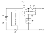
- Fig. 1 is a circuit diagram for illustrating an arrangement and an operating mechanism of a fuse element employed in a protection circuit coupled to a battery module which includes a lithium secondary battery.
- a protection circuit includes a fuse element 1, a sense resistor 20 for sensing an overcurrent, a microcontroller 30 for monitoring an occurrence of an overcurrent and operating the fuse element 10 when an overcurrent occurs, and a switch 40 for switching the flow of an operating current to the fuse element 10 in order to protect a battery module when an overcurrent occurs.
- the fuse element 10 is installed to a main line connected to the outermost terminal of the battery module.
- the main line represents a wire through which a charging current or a discharging current flows.
- Fig. 1 it is depicted that the fuse element 10 is installed at a high potential line (Pack+).
- the fuse element 10 is a three-terminal element, in which two terminals are connected to the main line through which a charging or discharging current flows and one terminal is connected to the switch 40.
- the fuse element includes a fuse 11 connected to the main line in series and disconnected at a specific temperature and a resistor 12 for applying heat to the fuse 11.
- the microcontroller 30 monitors the occurrence of an overcurrent by periodically detecting voltages at both ends of the sense resistor 20, and turns on the switch 40 if it is determined that an overcurrent occurs.
- the current flowing through the main line flows to the fuse element 10 by bypassing and is applied to the resistor 12. Accordingly, the Joule's heat generated at the resistor 12 is conducted to the fuse 1a to raise the temperature of the fuse 11. If the temperature of the fuse 11 increases to a melting temperature, the fuse 11 is fused to irreversibly cut the main line. If the main line is cut, the overcurrent does not flow any more, which solves problems caused from the overcurrent.
- the above techniques have several problems. For example, if the microcontroller 30 malfunctions, even though an overcurrent occurs, the switch 40 does not turn on. In this case, a current is not applied to the resistor 12 of the fuse element 10, and therefore the fuse element 10 does not operate. In addition, a space for disposing the fuse element 10 should be separately provided in the protection circuit, and a program algorithm for controlling operations of the fuse element 10 should be loaded on the microcontroller 30. Therefore, the spatial efficiency of the protection circuit deteriorates, and the load of the microcontroller 30 increases.
- the present disclosure is designed to solve the problems of the prior art, and therefore it is an object of the present disclosure to provide a battery module which may ensure safety in use by easily breaking a bus bar when a temperature increases due to the occurrence of an abnormality while the battery module is in use by configuring the bus bar for connecting a cell to an external terminal to have a double structure, and a bus bar applied thereto.
- a battery module which includes at least one unit cell; a case for accommodating the unit cell; and a bus bar electrically connected to the unit cell, wherein the bus bar includes a first metal plate; a second metal plate spaced apart from the first metal plate; and a metal bridge configured to connect the first metal plate and the second metal plate and having a lower melting point than the metal plate.
- the metal bridge may be a lead-free alloy containing tin (Sn) and copper (Cu) as main components.
- the content of the tin is preferably 80 to 98 wt%, and the content of the copper is preferably 2 to 20 wt%.
- the metal bridge may further include at least one additional metal selected from the group consisting of nickel (Ni), zinc (Zn) and silver (Ag).
- the content of the additional metal is preferably 0.01 to 10 wt%.
- the metal bridge is preferably formed to have a melting point of 150 to 300°C.
- the first metal plate and the second metal plate may be located on the same plane with a regular gap.
- the metal bridge may be joined to the first metal plate and the second metal plate on any one surface or both surfaces of the first metal plate and the second metal plate.
- the first metal plate and the second metal plate may have accommodation grooves formed in at least one of the upper and lower surfaces at one side end thereof, which face each other, and the metal bridge may be sized and shaped corresponding to the accommodation groove, and may be accommodated in a space formed by engagement of the accommodation grooves and joined to the first metal plate and the second metal plate.
- the first metal plate and the second metal plate may have a first bent portion and a second bent portion respectively formed at one side end of the first metal plate and one side end of the second metal plate which face each other, and the metal bridge may be accommodated in a space formed by engagement of the first bent portion and the second bent portion and joined to the first metal plate and the second metal plate.
- the first metal plate and the second metal plate may have accommodation grooves formed with a predetermined depth from surfaces thereof which face each other, and both sides of the metal bridge may be respectively inserted into the accommodation grooves and joined to the metal plate.
- the metal bridge may be directly interposed between surfaces of the first metal plate and the second metal plate which face each other and joined to the first metal plate and the second metal plate.
- the facing surfaces may have an inclined surface tapered toward the metal soldering bridge.
- the first metal plate and the second metal plate may be located so that one side of the first metal plate and one side of the second metal plate face each other while overlapping each other at least partially, and the metal bridge may be interposed in the facing region and joined to the first metal plate and the second metal plate.
- the first metal plate and the second metal plate may be located so that one side of the first metal plate and one side of the second metal plate face each other while overlapping each other at least partially, and the metal bridge may be formed at one side and the other side of a circumference of the facing region.
- the first metal plate and the second metal plate may be located so that one side of the first metal plate and one side of the second metal plate face each other while overlapping each other at least partially, and the metal bridge may be formed at the entire circumference of the facing region.
- the battery module may further include a rivet for fixing the first metal plate and the metal bridge and fixing the second metal plate and the metal bridge.
- one side of the first metal plate and one side of the second metal plate which face each other have a tapered shape which is narrowed toward an end thereof.
- the battery module may further include an external terminal installed at one side of the case, and the bus bar may be installed to connect the unit cell and the external terminal.
- a battery module which includes at least one unit cell including a cathode lead and an anode lead; a case for accommodating the unit cell; a first bus bar connected to the cathode lead; and a second bus bar connected to the anode lead, wherein the second bus bar includes a first metal plate; a second metal plate spaced apart from the first metal plate; and a metal bridge configured to connect the first metal plate and the second metal plate and having a lower melting point than the metal plate.
- a bus bar which is applied to a battery module and includes a first metal plate; a second metal plate spaced apart from the first metal plate; and a metal bridge configured to connect the first metal plate and the second metal plate and having a lower melting point than the metal plate.
- a bus bar is rapidly broken to ensure safety when the battery module is in use.
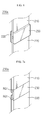
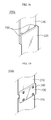
- a battery module 1 includes a battery cell 100, a bus bar 200, a case 300, an external terminal 311 and a voltage sensor 321.
- the battery cell 100 is formed by stacking unit modules 100A, 100B, 100C, 100D which are composed of at least one unit cells 110A, 110B and a cell cover 120 surrounding the unit cells 110A, 110B.
- the unit cells 110A, 110B includes an electrode assembly (not shown) accommodated in an exterior member and a first electrode lead 111 and a second electrode lead 112 respectively connected to uncoated parts of first and second electrode plates of the electrode assembly and respectively drawn toward one side and the other side of the exterior member.
- the first and second electrode plates are respectively a cathode plate and an anode plate, for example. Accordingly, the first and second electrode leads 111, 112 will be described as cathode and anode leads 111, 112.
- the cathode plate is made of aluminum (Al), and the anode plate is made of copper (Cu). Therefore, in aspect of weldability and minimization of electric resistance between the electrode plate and the electrode leads 111, 112, the cathode lead 111 is preferably made of aluminum (Al), identical to the cathode plate, and the anode lead 112 is preferably made of copper (Cu) or nickel (Ni)-coated copper (Cu), identical to the anode plate.
- the unit cells 110A, 110B and the unit modules 100A-100D may be connected to each other in series or in parallel depending on the use of the battery.
- the present disclosure will be described based on the case of the serial connection.
- the unit cells 110A, 110B are connected to each other in a way that a cathode lead 111 of a single unit cell 110A is coupled to an anode lead 112 of a unit cell 110B adjacent thereto.
- a cathode lead 111 of a unit cell 110A located at the outermost side of the rear surface (in R direction) and an anode lead 112 of a unit cell 110B located at the outermost side of the front surface (in F direction) are respectively coupled to a bus bar 200, described later.
- the present disclosure illustrates two unit cells 110A, 110B and four unit modules 100A-100D which are stacked.
- this is just an example, and it should be understood that the number of unit cells 110A, 110B and unit modules 100A-100D is not limited thereto.
- the bus bar 200 is coupled to the cathode lead 111 of the unit cell 110A located at the outermost side of the rear surface R of the battery cell 100 and the anode lead 112 of the unit cell 110B located at the outermost side of the front surface F and includes metal bridges for the connection among a first metal plate 210, a second metal plate 220 and metal plate 210, 220.
- the metal plates 210, 220 of the bus bars 200 respectively attached to the cathode lead 111 and the anode lead 112 may be made of different materials.
- the metal plates 210, 220 of the bus bar 200 attached to the cathode lead 111 is preferably made of aluminum, identical to the cathode lead 111
- the metal plates 210, 220 of the bus bar 200 attached to the anode lead 112 is preferably made of copper or nickel-coated copper, identical to the anode lead 112.
- the bus bars are substantially identical to each other except for their materials. Therefore, the bus bar 200 attached to the cathode lead 111 will be described in the present disclosure.
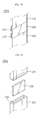
- the first metal plate 210 and second metal plate 220 are made of a metal with a thin plate shape.
- the first metal plate 210 has a lead coupling portion 210 formed by bending one side thereof into an approximately 'L' shape.
- the lead coupling portion 211 is respectively coupled to one side end of the cathode lead 111 and one side end of the cathode lead 112 by welding.
- the second metal plate 220 is located spaced apart from the first metal plate 220 by a predetermined distance and has a terminal groove 220a at an end opposite to the location of the first metal plate 210 so that the external terminal 311 may be inserted therein.
- the metal bridge 230 connects the metal plates 210, 220.
- Various embodiments in relation to detailed connection structures will be described later with reference to Figs. 5 to 11 , and only roles and properties of the metal bridge 230 will be described here.
- the metal bridge 230 is fused when the battery module 1 is overheated, and thus plays a role of releasing an electric connection between the first metal plate 210 and the second metal plate 220.
- the metal bridge 230 is made of a lead-free alloy containing tin (Sn) and copper (Cu) as main components and not containing lead (Pb) which is harmful to environments and human bodies, and has a melting point of about 150 to 300°C.
- the melting point range is lower than a melting point of a single metal selected from aluminum, copper and nickel-coated copper, which are used for the leads 111, 112 and/or the metal plates 210, 220. Therefore, it is possible to rapidly interrupt the overcurrent.
- the melting point range of the metal bridge 230 is determined in consideration of a maximum voltage and a maximum current which the bus bar 200 should endure, an overcurrent level to be interrupted by the bus bar 200, an electric property (resistance) and/or a mechanical property (tensile strength) demanded to the bus bar 200. If the melting point of the metal bridge 230 is lower than 150°C, the bus bar 200 may be broken by a current which flows when the battery module 1 operates normally. In addition, if the melting point of the metal bridge 230 is higher than 300°C, the overcurrent may not be effectively interrupted.
- the contents of tin and copper contained in the metal bridge 230 may be suitably adjusted according to the melting point of the metal bridge 230 or the electric property and/or physical property to be endowed to the metal bridge 230 or the bus bar 200.
- tin gives an influence on the melting point and tensile strength of the metal bridge 230.
- the content of tin is adjusted to 80 wt% or above, preferably in the range of 85 to 98 wt%.
- wt% is a unit based on the entire weight of the materials of the metal bridge 230.
- copper gives an influence on electric conductivity, melting point and tensile strength of the bus bar 200, and in consideration of such functions of copper, the content of copper is adjusted in the range of 2 to 20 wt%, preferably in the range of 4 to 15 wt%.
- the metal bridge 230 By adjusting the contents of tin and copper as described above, a good tensile strength of the metal bridge 230 may be obtained, and the increase of resistance caused by the metal bridge 230 may be controlled to be lower than several %. Moreover, the melting point of the metal bridge 230 may be adjusted in the range of 150 to 300°C.
- the metal bridge 230 may further include any one metal selected from nickel (Ni), zinc (Zn) and silver (Ag) in order to improve the electric property and/or mechanical property.
- the content of the additional metal may be adjusted according to the electric property and/or mechanical property to be endowed to the metal bridge 230, preferably in the range of 0.01 to 10 wt%.
- the present disclosure illustrates that the metal bridges 230 are applied to both the cathode lead 111 and the anode lead 112
- the present disclosure may be also applied to a case in which the metal bridge 230 is applied only to any one lead.
- the bus bar 200 is applied to only one lead
- the present disclosure is preferably applied to the anode lead 112 having a greater caloric value, and a general bus bar is applied to the cathode lead 111.
- the case 300 accommodates the battery cell 100 and includes a lower case 310 and an upper case 320.
- the lower case 310 has an open upper portion, is formed to surround a part of both sides of the battery cell 100 and the lower surface thereof, and has a pair of slits 310a.
- the slit 310a is formed at a location in one side of the lower case 310, which corresponds to the lead coupling portion 211 of the bus bar 200, and gives a space in which the lead coupling portion 211 is received when the battery cell 100 is inserted into the lower case 310. Therefore, the battery cell 100 and the bus bar 200 may be respectively located at an inner side and an outer side of the lower case 310 while maintaining an electric connection between them.
- an external terminal 311 is provided at a location on one side of the lower case 310, which corresponds to the terminal groove 220a of the bus bar 200, and formed to protrude out of the lower case 310.
- the external terminal 311 is sized and shaped corresponding to the terminal groove 220 of the bus bar 200 and gives a space through which the external terminal 311 may be inserted into the bus bar 200 when the battery cell 100 is received in the lower case 310.
- the external terminal 311 plays a role of electrically connecting an external device (not shown) to the battery cell 100.
- the external terminal 311 and the bus bar 200 may also be coupled by welding in aspect of minimization of contact resistance and improvement of coupling force between the external terminal 311 and the bus bar 200.
- the upper case 320 has an open lower portion and is formed to surround a part of both sides of the battery cell 100 inserted into the lower case 310, namely a part of the sides through which the electrode leads 111, 112 are drawn, and an upper surface thereof.
- the upper case 320 may be coupled to the lower case 310 using a bolt.
- the upper case 320 has sensor coupling units 320a at both sides thereof so that the voltage sensor 321 may be inserted therein.
- the voltage sensor 321 is electrically connected to the battery cell 100 in the sensor coupling unit 320a and senses a voltage of the battery cell 100.
- the bus bar 200 having a double structure in which the metal plates 210, 220 are connected by the metal bridge 230 is applied to the battery module 1 according to the present disclosure. Therefore, when an overcurrent occurs, the battery module 1 may ensure safety in use since the bus bar 200 is rapidly broken. In particular, by applying a current interrupting unit to the bus bar 200 which is installed at an outer side of the case, the battery module 1 may further reduce the possibility of firing or explosion in comparison to cases in which the current interrupting unit is applied to a part adjacent to an electrode assembly (not shown), for example the leads 111, 112.
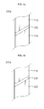
- bus bar 200a First, a structure of a bus bar 200a according to an embodiment of the present disclosure will be described with reference to Figs. 5 to 9c .
- Figs. 5 to 10 show various modifications of the bus bar 200a according to an embodiment of the present disclosure, and the bus bar 200a is formed by coupling the metal bridge 230 to the metal plates 210, 220 by welding.
- the metal bridge 230 plays a role of a soldering bridge which connects the metal plates 210, 220 to each other.
- the first metal plate 210 and the second metal plate 220 are located on the same plane with a regular gap, and the metal bridge 230 is formed on the upper surfaces of the metal plates 210, 220 and joined to the metal plates 210, 220. Even though Fig. 5 shows that the metal bridge 230 is formed only in the upper surfaces of the metal plates 210, 220, the metal bridge 230 may also be formed in both upper and lower surfaces of the metal plates 210, 220, which may reinforce a coupling force between the metal plates 210, 220.
- the first metal plate 210 and the second metal plate 220 are located on the same plane with a regular gap and have accommodation grooves RG1 formed in the upper surface thereof at one side end thereof which face each other.
- the metal bridge 230 is sized and shaped corresponding to the accommodation grooves RG2 ( ⁇ RG1), and the metal bridge 230 is accommodated in a space formed by engagement of the accommodation grooves RG1 and joined to the metal plates 210, 220.
- Fig. 7a shows that the accommodation grooves RG1 are formed only in the upper surfaces of the metal plates 210, 220, the accommodation grooves RG1 may also be formed in the lower surface or both upper and lower surfaces of the metal plates 210, 220.
- the first metal plate 210 and the second metal plate 220 are located on the same plane with a regular gap and have a first bent portion 210' and a second bent portion 220' formed at one side thereof which face each other. Meanwhile, the metal bridge 230 is accommodated in a space formed by engagement of the first bent portion 210' and the second bent portion 220' and joined to the metal plates 210, 220.
- the first metal plate 210 and the second metal plate 220 are located on the same plane with a regular gap and have accommodation grooves RG2 formed with a predetermined depth from surfaces thereof which face each other. Meanwhile, both sides of the metal bridge 230 are inserted into the accommodation grooves RG2 and joined to the metal plates 210, 220.
- the structures shown in Figs. 7a , 7b and 7c reinforce a coupling force between the metal plates 210, 220 and decrease a contact resistance since a contact area between the metal plates 210, 220 and the metal bridge 230 increases, in comparison to the structures shown in Figs. 5 and 6 .
- the first metal plate 210 and the second metal plate 220 are located on the same plane with a regular gap, and the metal bridge 230 is directly interposed between surfaces of the metal plates 210, 220 which face each other and joined to the metal plates 210, 220.
- Fig. 8b The structure of Fig. 8b is different from the structure of Fig. 8a in the point that surfaces of the metal plates 210, 220 which face each other have an inclined shape tapered toward the metal bridge. In this case, the contact area between the metal plates 210, 220 and the metal bridge 230 increases further, which reinforces a coupling force between the metal plates 210, 220 and decreases a contact resistance.
- the first metal plate 210 and the second metal plate 220 are located so that one side of the first metal plate 210 and one side of the second metal plate 220 face each other while overlapping each other at least partially, and the metal bridge 230 is interposed in the entire facing region and joined to the metal plates 210, 220.
- the structures of Figs. 9b and 9c are different from the structures of Fig. 9a in view of the area of the metal bridge 230 interposed between the metal plates 210, 220.
- the metal bridge 230 is formed only at one side and the other side among a circumference of the region where the metal plates 210, 220 faces each other.
- the bus bar 200 is broken rapidly.
- the metal bridge 230 may also be formed at the entire circumference of the facing region. In this case, it is expected that the metal bridge 230 will be broken more rapidly in comparison to the structure of Fig. 9a , and the coupling force between the metal plates 210, 220 will be more excellent in comparison to the structures of Figs. 9b and 9c .
- bus bar 200b according to another embodiment of the present disclosure will be described with reference to Fig. 10 .
- the bus bar 200b of Fig. 10 is different from the bus bar 200a of Fig. 5 in the point that a rivet 240 is further formed between the metal plates 210, 220 and the metal bridge 230.
- the rivet 240 plays a role of enhancing a coupling force between the metal plates 210, 220 and the metal bridge 230.
- Fig. 10 shows that the rivet 240 is additionally applied to the bus bar 200a of Fig. 5
- the present disclosure is not limited thereto, and the rivet 240 may also be applied to the structures of Figs. 6 to 7c .
- bus bar 200c according to another embodiment of the present disclosure will be described with reference to Fig. 11 .
- the bus bar 200c of Fig. 11 is different from the bus bar 200a of Fig. 5 in the point that one side of the first metal plate 210 and one side of the second metal plate 220 which face each other have tapered portions N1, N2 which are narrowed toward an end thereof.
- the bus bar 200c since electric resistances at the tapered portions N1, N2 increase in comparison to the bus bar 200a of Fig. 5 , more heat is generated when an overcurrent occurs, and therefore the bus bar 200c may be broken rapidly.
- Fig. 11 shows that the tapered portions N1, N2 are additionally formed at the bus bar 200a of Fig. 5
- the present disclosure is not limited thereto, and the tapered portions N1, N2 may also be applied to the structures of Figs. 6 to 9c .
- the bus bar 200c may be rapidly broken when an overcurrent occurs, the coupling force between the metal plates 210, 220 is excellent, and a contact resistance is low.
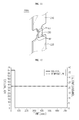
- the voltage of the battery module 1 measured between the external terminals 311 was kept at about 65V for about 50 seconds and then dropped to 0V. In other words, after about 50 seconds passed, the bus bar was broken by the short-circuit current. At this time, the temperature measured at the unit cells was constantly maintained at about 23°C through the short-circuit experiment.
- the bus bar 200a applied to the battery module 1 according to the present disclosure may ensure safety in use of a secondary battery by rapidly interrupting a short-circuit current before the temperature of unit cells increases in substance.
Landscapes
- Chemical & Material Sciences (AREA)
- Chemical Kinetics & Catalysis (AREA)
- Electrochemistry (AREA)
- General Chemical & Material Sciences (AREA)
- Engineering & Computer Science (AREA)
- Manufacturing & Machinery (AREA)
- Inorganic Chemistry (AREA)
- Connection Of Batteries Or Terminals (AREA)
- Battery Mounting, Suspending (AREA)
Applications Claiming Priority (2)
| Application Number | Priority Date | Filing Date | Title |
|---|---|---|---|
| KR20110125225 | 2011-11-28 | ||
| PCT/KR2012/010182 WO2013081375A1 (fr) | 2011-11-28 | 2012-11-28 | Module de batterie et barre omnibus appliquée au module de batterie |
Publications (3)
| Publication Number | Publication Date |
|---|---|
| EP2662913A1 true EP2662913A1 (fr) | 2013-11-13 |
| EP2662913A4 EP2662913A4 (fr) | 2015-04-15 |
| EP2662913B1 EP2662913B1 (fr) | 2016-04-20 |
Family
ID=48858257
Family Applications (1)
| Application Number | Title | Priority Date | Filing Date |
|---|---|---|---|
| EP12854353.5A Active EP2662913B1 (fr) | 2011-11-28 | 2012-11-28 | Module de batterie et barre omnibus appliquée au module de batterie |
Country Status (6)
| Country | Link |
|---|---|
| US (1) | US9577240B2 (fr) |
| EP (1) | EP2662913B1 (fr) |
| JP (1) | JP6270123B2 (fr) |
| KR (1) | KR101433199B1 (fr) |
| CN (1) | CN103460447B (fr) |
| WO (1) | WO2013081375A1 (fr) |
Cited By (6)
| Publication number | Priority date | Publication date | Assignee | Title |
|---|---|---|---|---|
| EP2876708A1 (fr) * | 2013-11-20 | 2015-05-27 | Samsung SDI Co., Ltd. | Batterie rechargeable ayant un fusible |
| EP2827404A4 (fr) * | 2012-08-02 | 2015-10-07 | Lg Chemical Ltd | Pièce de connexion de batterie secondaire, et module de batterie et pack de batterie la comprenant |
| US20160028068A1 (en) * | 2013-09-26 | 2016-01-28 | Lg Chem, Ltd. | Secondary battery and electrode lead assembly applied thereto |
| WO2018138654A1 (fr) * | 2017-01-26 | 2018-08-02 | Te Connectivity Corporation | Ensemble barre omnibus pour un système de batterie |
| EP2698847B1 (fr) * | 2012-01-03 | 2020-03-04 | LG Chem, Ltd. | Bloc-piles et barre de liaison qui y est rattachée |
| EP3843178A4 (fr) * | 2018-12-07 | 2021-11-03 | LG Chem, Ltd. | Module de batterie ayant une sécurité améliorée, bloc-batterie comprenant un module de batterie et véhicule comprenant un bloc-batterie |
Families Citing this family (34)
| Publication number | Priority date | Publication date | Assignee | Title |
|---|---|---|---|---|
| EP2757615B1 (fr) * | 2011-09-16 | 2017-08-02 | LG Chem, Ltd. | Élément de batterie secondaire, son procédé de fabrication, batterie secondaire fabriquée à l'aide d'un élément, et dispositif de batterie secondaire assemblé |
| KR101455769B1 (ko) * | 2012-05-08 | 2014-11-03 | 주식회사 엘지화학 | 전극 리드 및 이를 포함하는 이차전지 |
| US10218027B2 (en) | 2013-11-11 | 2019-02-26 | A123 Systems, LLC | Vehicle starter battery |
| KR101551000B1 (ko) * | 2013-12-12 | 2015-09-07 | 현대자동차주식회사 | 전기자동차의 고전압배터리 시스템 |
| KR101558694B1 (ko) | 2013-12-18 | 2015-10-07 | 현대자동차주식회사 | 차량의 고전압배터리 |
| WO2016085540A1 (fr) | 2014-11-26 | 2016-06-02 | Techtronic Industries Co. Ltd. | Bloc-batterie |
| KR102415749B1 (ko) * | 2015-08-05 | 2022-07-01 | 삼성에스디아이 주식회사 | 플렉시블 전지 |
| KR102016716B1 (ko) * | 2015-10-30 | 2019-09-02 | 주식회사 엘지화학 | 전지 팩 |
| US10032583B2 (en) * | 2016-02-17 | 2018-07-24 | Dexerials Corporation | Protective circuit substrate |
| KR101956028B1 (ko) | 2016-05-18 | 2019-03-08 | 현대자동차 주식회사 | 버스 플레이트 유닛 |
| KR102201344B1 (ko) * | 2017-05-26 | 2021-01-08 | 주식회사 엘지화학 | 배터리 모듈과 이를 포함하는 배터리 팩 및 자동차 |
| KR102209773B1 (ko) | 2017-05-29 | 2021-01-28 | 주식회사 엘지화학 | 배터리 모듈 |
| KR102148993B1 (ko) * | 2017-06-13 | 2020-08-27 | 주식회사 엘지화학 | 배터리 모듈 |
| WO2019003928A1 (fr) * | 2017-06-27 | 2019-01-03 | パナソニックIpマネジメント株式会社 | Barre omnibus et empilage de batteries |
| KR102163656B1 (ko) * | 2017-06-27 | 2020-10-08 | 주식회사 엘지화학 | 배터리 모듈과 이를 포함하는 배터리 팩 및 자동차 |
| KR102201342B1 (ko) | 2017-07-06 | 2021-01-08 | 주식회사 엘지화학 | 배터리 모듈과 이를 포함하는 배터리 팩 및 자동차 |
| US10569634B2 (en) * | 2017-08-18 | 2020-02-25 | GM Global Technology Operations LLC | Multi-functional cooling channel and busbar for battery cell pack |
| JP2019067678A (ja) * | 2017-10-03 | 2019-04-25 | カルソニックカンセイ株式会社 | 組電池 |
| KR102350459B1 (ko) * | 2017-12-07 | 2022-01-11 | 주식회사 엘지에너지솔루션 | 원통형 이차전지 모듈 |
| US10644282B2 (en) | 2018-01-23 | 2020-05-05 | Nio Usa, Inc. | Staggered battery cell array with two-dimensional inline terminal edges |
| KR102382386B1 (ko) * | 2018-02-09 | 2022-04-01 | 주식회사 엘지에너지솔루션 | 전류 차단부를 구비한 버스바 및 그것을 포함한 배터리 모듈 |
| US10741808B2 (en) | 2018-03-15 | 2020-08-11 | Nio Usa, Inc. | Unified battery module with integrated battery cell structural support |
| WO2019164974A1 (fr) * | 2018-02-20 | 2019-08-29 | Nio Usa, Inc. | Barre omnibus effilée à densité de courant uniforme |
| US10892465B2 (en) | 2018-03-22 | 2021-01-12 | Nio Usa, Inc. | Battery cell cover including terminal short isolation feature |
| US10707471B2 (en) | 2018-03-22 | 2020-07-07 | Nio Usa, Inc. | Single side cell-to-cell battery module interconnection |
| US10741889B2 (en) | 2018-03-22 | 2020-08-11 | Nio Usa, Inc. | Multiple-zone thermocouple battery module temperature monitoring system |
| US10784486B2 (en) | 2018-02-20 | 2020-09-22 | Nio Usa, Inc. | Uniform current density tapered busbar |
| KR20210121786A (ko) * | 2020-03-31 | 2021-10-08 | 주식회사 엘지에너지솔루션 | 이종금속으로 이루어진 hv 버스 바 및 이의 제조 방법 |
| KR102519837B1 (ko) * | 2020-04-03 | 2023-04-10 | 컨템포러리 엠퍼렉스 테크놀로지 씨오., 리미티드 | 배터리 모듈, 배터리 팩 및 배터리를 전원으로 사용하는 장치 |
| KR20220011430A (ko) * | 2020-07-21 | 2022-01-28 | 주식회사 엘지에너지솔루션 | 전지 모듈 및 이를 포함하는 전지팩 |
| CN111785885B (zh) * | 2020-07-23 | 2022-07-19 | 中创新航科技股份有限公司 | 电池组件及电动设备 |
| KR20220041470A (ko) * | 2020-09-25 | 2022-04-01 | 현대자동차주식회사 | 배터리 모듈 및 이를 포함하는 배터리 팩 |
| US11850956B2 (en) | 2021-05-14 | 2023-12-26 | Deere & Company | Battery arrangement of a compact electric tractor |
| CN115764176A (zh) * | 2022-11-30 | 2023-03-07 | 厦门海辰储能科技股份有限公司 | 汇流单元、电池模组及用电设备 |
Citations (7)
| Publication number | Priority date | Publication date | Assignee | Title |
|---|---|---|---|---|
| EP0964419A1 (fr) * | 1998-06-11 | 1999-12-15 | Uchihashi Estec Co., Ltd. | Fusible thermique de faible épaisseur et procédé de fabrication |
| JP2007035280A (ja) * | 2005-07-22 | 2007-02-08 | Uchihashi Estec Co Ltd | 銅リード線とヒューズエレメントとのレーザ溶接方法 |
| US20080192399A1 (en) * | 2007-02-14 | 2008-08-14 | Sheng-Chung Chen | Secondary battery apparatus and a protection circuit thereof |
| US20090297892A1 (en) * | 2008-04-14 | 2009-12-03 | A123 Systems, Inc. | Flexible Voltage Nested Battery Module Design |
| US20100176910A1 (en) * | 2007-03-26 | 2010-07-15 | Norbert Knab | Fusible alloy element, thermal fuse with fusible alloy element and method for producing a thermal fuse |
| WO2010133176A1 (fr) * | 2009-05-21 | 2010-11-25 | Byd Company Limited | Dispositif de fusible pour courant et ensemble batterie le comprenant |
| US20100323235A1 (en) * | 2008-03-04 | 2010-12-23 | Norio Takami | Non-aqueous electrolyte secondary battery and combined battery |
Family Cites Families (13)
| Publication number | Priority date | Publication date | Assignee | Title |
|---|---|---|---|---|
| JP2001256937A (ja) * | 2000-03-14 | 2001-09-21 | Matsushita Electric Ind Co Ltd | 組電池及び電池パック |
| KR100822184B1 (ko) * | 2001-09-19 | 2008-04-16 | 삼성에스디아이 주식회사 | 이차 전지용 온도 퓨즈 |
| JP3761846B2 (ja) * | 2002-07-11 | 2006-03-29 | 内橋エステック株式会社 | 合金型温度ヒューズ及び温度ヒューズエレメント用線材 |
| KR100561308B1 (ko) * | 2004-05-31 | 2006-03-15 | 삼성에스디아이 주식회사 | 이차전지 |
| US20060127754A1 (en) * | 2004-12-14 | 2006-06-15 | Toyota Jidosha Kabushiki Kaisha. | Battery pack |
| CA2592475C (fr) * | 2004-12-24 | 2010-03-30 | Lg Chem, Ltd. | Assemblage de carte de detection pour module de batterie secondaire |
| CN101253662B (zh) * | 2005-07-22 | 2013-03-27 | 力特保险丝有限公司 | 整体熔融组件和形成熔融电部件的方法 |
| KR101112447B1 (ko) * | 2006-11-13 | 2012-02-20 | 주식회사 엘지화학 | 향상된 안전성의 이차전지 |
| KR100984576B1 (ko) * | 2007-05-15 | 2010-09-30 | 주식회사 엘지화학 | 저항값이 조절된 전극 탭 또는 전지간 연결용 도선 |
| KR100878285B1 (ko) * | 2007-06-05 | 2009-01-12 | 삼성에스디아이 주식회사 | 배터리 팩 |
| US20090159354A1 (en) * | 2007-12-25 | 2009-06-25 | Wenfeng Jiang | Battery system having interconnected battery packs each having multiple electrochemical storage cells |
| US9413031B2 (en) * | 2009-03-24 | 2016-08-09 | Lenovo (Singapore) Pte. Ltd. | Apparatus and system for an internal fuse in a battery cell |
| KR101130294B1 (ko) * | 2010-03-30 | 2012-08-23 | 에스비리모티브 주식회사 | 이차 전지 |
-
2012
- 2012-11-28 EP EP12854353.5A patent/EP2662913B1/fr active Active
- 2012-11-28 KR KR1020120135793A patent/KR101433199B1/ko active IP Right Grant
- 2012-11-28 WO PCT/KR2012/010182 patent/WO2013081375A1/fr active Application Filing
- 2012-11-28 JP JP2013558802A patent/JP6270123B2/ja active Active
- 2012-11-28 CN CN201280015204.1A patent/CN103460447B/zh active Active
-
2013
- 2013-08-05 US US13/959,381 patent/US9577240B2/en active Active
Patent Citations (7)
| Publication number | Priority date | Publication date | Assignee | Title |
|---|---|---|---|---|
| EP0964419A1 (fr) * | 1998-06-11 | 1999-12-15 | Uchihashi Estec Co., Ltd. | Fusible thermique de faible épaisseur et procédé de fabrication |
| JP2007035280A (ja) * | 2005-07-22 | 2007-02-08 | Uchihashi Estec Co Ltd | 銅リード線とヒューズエレメントとのレーザ溶接方法 |
| US20080192399A1 (en) * | 2007-02-14 | 2008-08-14 | Sheng-Chung Chen | Secondary battery apparatus and a protection circuit thereof |
| US20100176910A1 (en) * | 2007-03-26 | 2010-07-15 | Norbert Knab | Fusible alloy element, thermal fuse with fusible alloy element and method for producing a thermal fuse |
| US20100323235A1 (en) * | 2008-03-04 | 2010-12-23 | Norio Takami | Non-aqueous electrolyte secondary battery and combined battery |
| US20090297892A1 (en) * | 2008-04-14 | 2009-12-03 | A123 Systems, Inc. | Flexible Voltage Nested Battery Module Design |
| WO2010133176A1 (fr) * | 2009-05-21 | 2010-11-25 | Byd Company Limited | Dispositif de fusible pour courant et ensemble batterie le comprenant |
Non-Patent Citations (1)
| Title |
|---|
| See also references of WO2013081375A1 * |
Cited By (14)
| Publication number | Priority date | Publication date | Assignee | Title |
|---|---|---|---|---|
| EP2698847B1 (fr) * | 2012-01-03 | 2020-03-04 | LG Chem, Ltd. | Bloc-piles et barre de liaison qui y est rattachée |
| EP2827404A4 (fr) * | 2012-08-02 | 2015-10-07 | Lg Chemical Ltd | Pièce de connexion de batterie secondaire, et module de batterie et pack de batterie la comprenant |
| EP2950371A4 (fr) * | 2013-09-26 | 2016-09-28 | Lg Chemical Ltd | Batterie rechargeable et ensemble en plomb pour électrode appliqué à celle-ci |
| US10026949B2 (en) * | 2013-09-26 | 2018-07-17 | Lg Chem, Ltd. | Secondary battery and electrode lead assembly applied thereto |
| US20160028068A1 (en) * | 2013-09-26 | 2016-01-28 | Lg Chem, Ltd. | Secondary battery and electrode lead assembly applied thereto |
| US9490469B2 (en) | 2013-11-20 | 2016-11-08 | Samsung Sdi Co., Ltd. | Rechargeable battery having fuse |
| EP2876708A1 (fr) * | 2013-11-20 | 2015-05-27 | Samsung SDI Co., Ltd. | Batterie rechargeable ayant un fusible |
| JP2015103521A (ja) * | 2013-11-20 | 2015-06-04 | 三星エスディアイ株式会社Samsung SDI Co.,Ltd. | 二次電池 |
| CN104659323B (zh) * | 2013-11-20 | 2019-01-29 | 三星Sdi株式会社 | 具有熔断体的可再充电电池 |
| CN104659323A (zh) * | 2013-11-20 | 2015-05-27 | 三星Sdi株式会社 | 具有熔断体的可再充电电池 |
| WO2018138654A1 (fr) * | 2017-01-26 | 2018-08-02 | Te Connectivity Corporation | Ensemble barre omnibus pour un système de batterie |
| US10333129B2 (en) | 2017-01-26 | 2019-06-25 | Te Connectivity Corporation | Buss bar assembly for a battery system |
| EP3843178A4 (fr) * | 2018-12-07 | 2021-11-03 | LG Chem, Ltd. | Module de batterie ayant une sécurité améliorée, bloc-batterie comprenant un module de batterie et véhicule comprenant un bloc-batterie |
| US11658364B2 (en) | 2018-12-07 | 2023-05-23 | Lg Energy Solution, Ltd. | Battery module with improved safety, battery pack including the battery module and vehicle including the battery pack |
Also Published As
| Publication number | Publication date |
|---|---|
| CN103460447B (zh) | 2016-06-15 |
| EP2662913A4 (fr) | 2015-04-15 |
| EP2662913B1 (fr) | 2016-04-20 |
| US20130323549A1 (en) | 2013-12-05 |
| KR20130059301A (ko) | 2013-06-05 |
| KR101433199B1 (ko) | 2014-08-26 |
| JP2014512071A (ja) | 2014-05-19 |
| US9577240B2 (en) | 2017-02-21 |
| JP6270123B2 (ja) | 2018-01-31 |
| WO2013081375A1 (fr) | 2013-06-06 |
| CN103460447A (zh) | 2013-12-18 |
Similar Documents
| Publication | Publication Date | Title |
|---|---|---|
| EP2662913B1 (fr) | Module de batterie et barre omnibus appliquée au module de batterie | |
| US9887413B2 (en) | Battery pack and connecting bar applied thereto | |
| US8890648B2 (en) | Connecting element for secondary battery, and battery module and battery pack including the same | |
| US9444088B2 (en) | Overcurrent shut-off device and secondary battery system comprising the same | |
| EP2722911B1 (fr) | Connecteur à souder, module de batterie le comprenant et bloc-batterie comprenant le module de batterie. | |
| KR101812273B1 (ko) | 전류 차단용 버스 바를 구비하는 배터리 모듈 | |
| EP2887430B1 (fr) | Élément de raccordement pour batterie secondaire et batterie secondaire la comprenant | |
| KR101614434B1 (ko) | 안전성이 향상된 배터리 셀 | |
| US9269960B2 (en) | Electrode lead and secondary battery having the same | |
| KR20140064093A (ko) | 안전성이 향상된 배터리 모듈 및 이에 적용되는 버스 바 | |
| KR20140110190A (ko) | 이차전지용 안전 킷 및 이를 포함하는 이차전지 | |
| KR20140011206A (ko) | 이차전지용 커넥팅 부품, 이를 포함하는 배터리 모듈 및 배터리 팩 |
Legal Events
| Date | Code | Title | Description |
|---|---|---|---|
| PUAI | Public reference made under article 153(3) epc to a published international application that has entered the european phase |
Free format text: ORIGINAL CODE: 0009012 |
|
| 17P | Request for examination filed |
Effective date: 20130809 |
|
| AK | Designated contracting states |
Kind code of ref document: A1 Designated state(s): AL AT BE BG CH CY CZ DE DK EE ES FI FR GB GR HR HU IE IS IT LI LT LU LV MC MK MT NL NO PL PT RO RS SE SI SK SM TR |
|
| DAX | Request for extension of the european patent (deleted) | ||
| RIN1 | Information on inventor provided before grant (corrected) |
Inventor name: CHOI, JUN-SEOK Inventor name: LEE, JIN-KYU Inventor name: CHOI, SEUNG-DON Inventor name: KIM, TAE-HYUCK Inventor name: SHIN, IN-CHEOL Inventor name: KANG, DAL-MO Inventor name: ROH, TAE-HWAN Inventor name: YANG, JUNG-HOON Inventor name: KIM, SEONG-TAE Inventor name: JANG, MIN-CHUL |
|
| RA4 | Supplementary search report drawn up and despatched (corrected) |
Effective date: 20150317 |
|
| RIC1 | Information provided on ipc code assigned before grant |
Ipc: H01M 2/34 20060101ALI20150311BHEP Ipc: H01M 2/20 20060101ALI20150311BHEP Ipc: H01M 2/26 20060101ALI20150311BHEP Ipc: H01M 2/30 20060101AFI20150311BHEP |
|
| GRAP | Despatch of communication of intention to grant a patent |
Free format text: ORIGINAL CODE: EPIDOSNIGR1 |
|
| RIC1 | Information provided on ipc code assigned before grant |
Ipc: H01M 2/10 20060101ALI20151117BHEP Ipc: H01M 2/30 20060101AFI20151117BHEP Ipc: H01M 2/34 20060101ALI20151117BHEP Ipc: H01M 2/20 20060101ALI20151117BHEP Ipc: H01M 2/26 20060101ALI20151117BHEP |
|
| INTG | Intention to grant announced |
Effective date: 20151201 |
|
| GRAS | Grant fee paid |
Free format text: ORIGINAL CODE: EPIDOSNIGR3 |
|
| GRAA | (expected) grant |
Free format text: ORIGINAL CODE: 0009210 |
|
| INTG | Intention to grant announced |
Effective date: 20160223 |
|
| AK | Designated contracting states |
Kind code of ref document: B1 Designated state(s): AL AT BE BG CH CY CZ DE DK EE ES FI FR GB GR HR HU IE IS IT LI LT LU LV MC MK MT NL NO PL PT RO RS SE SI SK SM TR |
|
| REG | Reference to a national code |
Ref country code: GB Ref legal event code: FG4D |
|
| REG | Reference to a national code |
Ref country code: CH Ref legal event code: EP |
|
| REG | Reference to a national code |
Ref country code: AT Ref legal event code: REF Ref document number: 793301 Country of ref document: AT Kind code of ref document: T Effective date: 20160515 |
|
| REG | Reference to a national code |
Ref country code: IE Ref legal event code: FG4D |
|
| REG | Reference to a national code |
Ref country code: DE Ref legal event code: R096 Ref document number: 602012017492 Country of ref document: DE |
|
| REG | Reference to a national code |
Ref country code: LT Ref legal event code: MG4D |
|
| REG | Reference to a national code |
Ref country code: AT Ref legal event code: MK05 Ref document number: 793301 Country of ref document: AT Kind code of ref document: T Effective date: 20160420 |
|
| REG | Reference to a national code |
Ref country code: NL Ref legal event code: MP Effective date: 20160420 |
|
| PG25 | Lapsed in a contracting state [announced via postgrant information from national office to epo] |
Ref country code: NO Free format text: LAPSE BECAUSE OF FAILURE TO SUBMIT A TRANSLATION OF THE DESCRIPTION OR TO PAY THE FEE WITHIN THE PRESCRIBED TIME-LIMIT Effective date: 20160720 Ref country code: LT Free format text: LAPSE BECAUSE OF FAILURE TO SUBMIT A TRANSLATION OF THE DESCRIPTION OR TO PAY THE FEE WITHIN THE PRESCRIBED TIME-LIMIT Effective date: 20160420 Ref country code: FI Free format text: LAPSE BECAUSE OF FAILURE TO SUBMIT A TRANSLATION OF THE DESCRIPTION OR TO PAY THE FEE WITHIN THE PRESCRIBED TIME-LIMIT Effective date: 20160420 Ref country code: NL Free format text: LAPSE BECAUSE OF FAILURE TO SUBMIT A TRANSLATION OF THE DESCRIPTION OR TO PAY THE FEE WITHIN THE PRESCRIBED TIME-LIMIT Effective date: 20160420 Ref country code: PL Free format text: LAPSE BECAUSE OF FAILURE TO SUBMIT A TRANSLATION OF THE DESCRIPTION OR TO PAY THE FEE WITHIN THE PRESCRIBED TIME-LIMIT Effective date: 20160420 |
|
| REG | Reference to a national code |
Ref country code: FR Ref legal event code: PLFP Year of fee payment: 5 |
|
| PG25 | Lapsed in a contracting state [announced via postgrant information from national office to epo] |
Ref country code: SE Free format text: LAPSE BECAUSE OF FAILURE TO SUBMIT A TRANSLATION OF THE DESCRIPTION OR TO PAY THE FEE WITHIN THE PRESCRIBED TIME-LIMIT Effective date: 20160420 Ref country code: ES Free format text: LAPSE BECAUSE OF FAILURE TO SUBMIT A TRANSLATION OF THE DESCRIPTION OR TO PAY THE FEE WITHIN THE PRESCRIBED TIME-LIMIT Effective date: 20160420 Ref country code: AT Free format text: LAPSE BECAUSE OF FAILURE TO SUBMIT A TRANSLATION OF THE DESCRIPTION OR TO PAY THE FEE WITHIN THE PRESCRIBED TIME-LIMIT Effective date: 20160420 Ref country code: RS Free format text: LAPSE BECAUSE OF FAILURE TO SUBMIT A TRANSLATION OF THE DESCRIPTION OR TO PAY THE FEE WITHIN THE PRESCRIBED TIME-LIMIT Effective date: 20160420 Ref country code: HR Free format text: LAPSE BECAUSE OF FAILURE TO SUBMIT A TRANSLATION OF THE DESCRIPTION OR TO PAY THE FEE WITHIN THE PRESCRIBED TIME-LIMIT Effective date: 20160420 Ref country code: GR Free format text: LAPSE BECAUSE OF FAILURE TO SUBMIT A TRANSLATION OF THE DESCRIPTION OR TO PAY THE FEE WITHIN THE PRESCRIBED TIME-LIMIT Effective date: 20160721 Ref country code: PT Free format text: LAPSE BECAUSE OF FAILURE TO SUBMIT A TRANSLATION OF THE DESCRIPTION OR TO PAY THE FEE WITHIN THE PRESCRIBED TIME-LIMIT Effective date: 20160822 Ref country code: LV Free format text: LAPSE BECAUSE OF FAILURE TO SUBMIT A TRANSLATION OF THE DESCRIPTION OR TO PAY THE FEE WITHIN THE PRESCRIBED TIME-LIMIT Effective date: 20160420 |
|
| PG25 | Lapsed in a contracting state [announced via postgrant information from national office to epo] |
Ref country code: IT Free format text: LAPSE BECAUSE OF FAILURE TO SUBMIT A TRANSLATION OF THE DESCRIPTION OR TO PAY THE FEE WITHIN THE PRESCRIBED TIME-LIMIT Effective date: 20160420 Ref country code: BE Free format text: LAPSE BECAUSE OF FAILURE TO SUBMIT A TRANSLATION OF THE DESCRIPTION OR TO PAY THE FEE WITHIN THE PRESCRIBED TIME-LIMIT Effective date: 20160420 |
|
| REG | Reference to a national code |
Ref country code: DE Ref legal event code: R097 Ref document number: 602012017492 Country of ref document: DE |
|
| PG25 | Lapsed in a contracting state [announced via postgrant information from national office to epo] |
Ref country code: CZ Free format text: LAPSE BECAUSE OF FAILURE TO SUBMIT A TRANSLATION OF THE DESCRIPTION OR TO PAY THE FEE WITHIN THE PRESCRIBED TIME-LIMIT Effective date: 20160420 Ref country code: RO Free format text: LAPSE BECAUSE OF FAILURE TO SUBMIT A TRANSLATION OF THE DESCRIPTION OR TO PAY THE FEE WITHIN THE PRESCRIBED TIME-LIMIT Effective date: 20160420 Ref country code: SK Free format text: LAPSE BECAUSE OF FAILURE TO SUBMIT A TRANSLATION OF THE DESCRIPTION OR TO PAY THE FEE WITHIN THE PRESCRIBED TIME-LIMIT Effective date: 20160420 Ref country code: DK Free format text: LAPSE BECAUSE OF FAILURE TO SUBMIT A TRANSLATION OF THE DESCRIPTION OR TO PAY THE FEE WITHIN THE PRESCRIBED TIME-LIMIT Effective date: 20160420 Ref country code: EE Free format text: LAPSE BECAUSE OF FAILURE TO SUBMIT A TRANSLATION OF THE DESCRIPTION OR TO PAY THE FEE WITHIN THE PRESCRIBED TIME-LIMIT Effective date: 20160420 |
|
| PLBE | No opposition filed within time limit |
Free format text: ORIGINAL CODE: 0009261 |
|
| STAA | Information on the status of an ep patent application or granted ep patent |
Free format text: STATUS: NO OPPOSITION FILED WITHIN TIME LIMIT |
|
| PG25 | Lapsed in a contracting state [announced via postgrant information from national office to epo] |
Ref country code: SM Free format text: LAPSE BECAUSE OF FAILURE TO SUBMIT A TRANSLATION OF THE DESCRIPTION OR TO PAY THE FEE WITHIN THE PRESCRIBED TIME-LIMIT Effective date: 20160420 |
|
| 26N | No opposition filed |
Effective date: 20170123 |
|
| PG25 | Lapsed in a contracting state [announced via postgrant information from national office to epo] |
Ref country code: SI Free format text: LAPSE BECAUSE OF FAILURE TO SUBMIT A TRANSLATION OF THE DESCRIPTION OR TO PAY THE FEE WITHIN THE PRESCRIBED TIME-LIMIT Effective date: 20160420 |
|
| REG | Reference to a national code |
Ref country code: CH Ref legal event code: PL |
|
| PG25 | Lapsed in a contracting state [announced via postgrant information from national office to epo] |
Ref country code: CH Free format text: LAPSE BECAUSE OF NON-PAYMENT OF DUE FEES Effective date: 20161130 Ref country code: LI Free format text: LAPSE BECAUSE OF NON-PAYMENT OF DUE FEES Effective date: 20161130 |
|
| REG | Reference to a national code |
Ref country code: IE Ref legal event code: MM4A |
|
| PG25 | Lapsed in a contracting state [announced via postgrant information from national office to epo] |
Ref country code: LU Free format text: LAPSE BECAUSE OF NON-PAYMENT OF DUE FEES Effective date: 20161130 |
|
| REG | Reference to a national code |
Ref country code: FR Ref legal event code: PLFP Year of fee payment: 6 |
|
| PG25 | Lapsed in a contracting state [announced via postgrant information from national office to epo] |
Ref country code: IE Free format text: LAPSE BECAUSE OF NON-PAYMENT OF DUE FEES Effective date: 20161128 |
|
| PG25 | Lapsed in a contracting state [announced via postgrant information from national office to epo] |
Ref country code: CY Free format text: LAPSE BECAUSE OF FAILURE TO SUBMIT A TRANSLATION OF THE DESCRIPTION OR TO PAY THE FEE WITHIN THE PRESCRIBED TIME-LIMIT Effective date: 20160420 Ref country code: HU Free format text: LAPSE BECAUSE OF FAILURE TO SUBMIT A TRANSLATION OF THE DESCRIPTION OR TO PAY THE FEE WITHIN THE PRESCRIBED TIME-LIMIT; INVALID AB INITIO Effective date: 20121128 |
|
| PG25 | Lapsed in a contracting state [announced via postgrant information from national office to epo] |
Ref country code: MC Free format text: LAPSE BECAUSE OF FAILURE TO SUBMIT A TRANSLATION OF THE DESCRIPTION OR TO PAY THE FEE WITHIN THE PRESCRIBED TIME-LIMIT Effective date: 20160420 Ref country code: MK Free format text: LAPSE BECAUSE OF FAILURE TO SUBMIT A TRANSLATION OF THE DESCRIPTION OR TO PAY THE FEE WITHIN THE PRESCRIBED TIME-LIMIT Effective date: 20160420 Ref country code: IS Free format text: LAPSE BECAUSE OF FAILURE TO SUBMIT A TRANSLATION OF THE DESCRIPTION OR TO PAY THE FEE WITHIN THE PRESCRIBED TIME-LIMIT Effective date: 20160420 |
|
| PG25 | Lapsed in a contracting state [announced via postgrant information from national office to epo] |
Ref country code: BG Free format text: LAPSE BECAUSE OF FAILURE TO SUBMIT A TRANSLATION OF THE DESCRIPTION OR TO PAY THE FEE WITHIN THE PRESCRIBED TIME-LIMIT Effective date: 20160420 |
|
| PG25 | Lapsed in a contracting state [announced via postgrant information from national office to epo] |
Ref country code: MT Free format text: LAPSE BECAUSE OF NON-PAYMENT OF DUE FEES Effective date: 20161128 |
|
| REG | Reference to a national code |
Ref country code: FR Ref legal event code: PLFP Year of fee payment: 7 |
|
| PG25 | Lapsed in a contracting state [announced via postgrant information from national office to epo] |
Ref country code: AL Free format text: LAPSE BECAUSE OF FAILURE TO SUBMIT A TRANSLATION OF THE DESCRIPTION OR TO PAY THE FEE WITHIN THE PRESCRIBED TIME-LIMIT Effective date: 20160420 Ref country code: TR Free format text: LAPSE BECAUSE OF FAILURE TO SUBMIT A TRANSLATION OF THE DESCRIPTION OR TO PAY THE FEE WITHIN THE PRESCRIBED TIME-LIMIT Effective date: 20160420 |
|
| REG | Reference to a national code |
Ref country code: DE Ref legal event code: R079 Ref document number: 602012017492 Country of ref document: DE Free format text: PREVIOUS MAIN CLASS: H01M0002300000 Ipc: H01M0050543000 |
|
| REG | Reference to a national code |
Ref country code: DE Ref legal event code: R081 Ref document number: 602012017492 Country of ref document: DE Owner name: LG ENERGY SOLUTION LTD., KR Free format text: FORMER OWNER: LG CHEM. LTD., SEOUL, KR Ref country code: DE Ref legal event code: R081 Ref document number: 602012017492 Country of ref document: DE Owner name: LG ENERGY SOLUTION, LTD., KR Free format text: FORMER OWNER: LG CHEM. LTD., SEOUL, KR |
|
| P01 | Opt-out of the competence of the unified patent court (upc) registered |
Effective date: 20230512 |
|
| REG | Reference to a national code |
Ref country code: GB Ref legal event code: 732E Free format text: REGISTERED BETWEEN 20230824 AND 20230831 |
|
| REG | Reference to a national code |
Ref country code: DE Ref legal event code: R081 Ref document number: 602012017492 Country of ref document: DE Owner name: LG ENERGY SOLUTION, LTD., KR Free format text: FORMER OWNER: LG ENERGY SOLUTION LTD., SEOUL, KR |
|
| PGFP | Annual fee paid to national office [announced via postgrant information from national office to epo] |
Ref country code: GB Payment date: 20231023 Year of fee payment: 12 |
|
| PGFP | Annual fee paid to national office [announced via postgrant information from national office to epo] |
Ref country code: FR Payment date: 20231024 Year of fee payment: 12 Ref country code: DE Payment date: 20231023 Year of fee payment: 12 |