EP2662480A1 - Textilteil, Verbundwerkstoffelement mit Textilteil und deren Herstellungsverfahren - Google Patents
Textilteil, Verbundwerkstoffelement mit Textilteil und deren Herstellungsverfahren Download PDFInfo
- Publication number
- EP2662480A1 EP2662480A1 EP12167731.4A EP12167731A EP2662480A1 EP 2662480 A1 EP2662480 A1 EP 2662480A1 EP 12167731 A EP12167731 A EP 12167731A EP 2662480 A1 EP2662480 A1 EP 2662480A1
- Authority
- EP
- European Patent Office
- Prior art keywords
- reinforcing
- binding
- section
- threads
- warp
- Prior art date
- Legal status (The legal status is an assumption and is not a legal conclusion. Google has not performed a legal analysis and makes no representation as to the accuracy of the status listed.)
- Granted
Links
Images




Classifications
-
- D—TEXTILES; PAPER
- D03—WEAVING
- D03D—WOVEN FABRICS; METHODS OF WEAVING; LOOMS
- D03D13/00—Woven fabrics characterised by the special disposition of the warp or weft threads, e.g. with curved weft threads, with discontinuous warp threads, with diagonal warp or weft
-
- D—TEXTILES; PAPER
- D03—WEAVING
- D03D—WOVEN FABRICS; METHODS OF WEAVING; LOOMS
- D03D13/00—Woven fabrics characterised by the special disposition of the warp or weft threads, e.g. with curved weft threads, with discontinuous warp threads, with diagonal warp or weft
- D03D13/006—With additional leno yarn
-
- B—PERFORMING OPERATIONS; TRANSPORTING
- B29—WORKING OF PLASTICS; WORKING OF SUBSTANCES IN A PLASTIC STATE IN GENERAL
- B29C—SHAPING OR JOINING OF PLASTICS; SHAPING OF MATERIAL IN A PLASTIC STATE, NOT OTHERWISE PROVIDED FOR; AFTER-TREATMENT OF THE SHAPED PRODUCTS, e.g. REPAIRING
- B29C45/00—Injection moulding, i.e. forcing the required volume of moulding material through a nozzle into a closed mould; Apparatus therefor
- B29C45/0005—Injection moulding, i.e. forcing the required volume of moulding material through a nozzle into a closed mould; Apparatus therefor using fibre reinforcements
-
- B—PERFORMING OPERATIONS; TRANSPORTING
- B29—WORKING OF PLASTICS; WORKING OF SUBSTANCES IN A PLASTIC STATE IN GENERAL
- B29C—SHAPING OR JOINING OF PLASTICS; SHAPING OF MATERIAL IN A PLASTIC STATE, NOT OTHERWISE PROVIDED FOR; AFTER-TREATMENT OF THE SHAPED PRODUCTS, e.g. REPAIRING
- B29C70/00—Shaping composites, i.e. plastics material comprising reinforcements, fillers or preformed parts, e.g. inserts
- B29C70/04—Shaping composites, i.e. plastics material comprising reinforcements, fillers or preformed parts, e.g. inserts comprising reinforcements only, e.g. self-reinforcing plastics
- B29C70/06—Fibrous reinforcements only
- B29C70/10—Fibrous reinforcements only characterised by the structure of fibrous reinforcements, e.g. hollow fibres
- B29C70/16—Fibrous reinforcements only characterised by the structure of fibrous reinforcements, e.g. hollow fibres using fibres of substantial or continuous length
- B29C70/22—Fibrous reinforcements only characterised by the structure of fibrous reinforcements, e.g. hollow fibres using fibres of substantial or continuous length oriented in at least two directions forming a two-dimensional [2D] structure
-
- B—PERFORMING OPERATIONS; TRANSPORTING
- B29—WORKING OF PLASTICS; WORKING OF SUBSTANCES IN A PLASTIC STATE IN GENERAL
- B29C—SHAPING OR JOINING OF PLASTICS; SHAPING OF MATERIAL IN A PLASTIC STATE, NOT OTHERWISE PROVIDED FOR; AFTER-TREATMENT OF THE SHAPED PRODUCTS, e.g. REPAIRING
- B29C70/00—Shaping composites, i.e. plastics material comprising reinforcements, fillers or preformed parts, e.g. inserts
- B29C70/04—Shaping composites, i.e. plastics material comprising reinforcements, fillers or preformed parts, e.g. inserts comprising reinforcements only, e.g. self-reinforcing plastics
- B29C70/28—Shaping operations therefor
- B29C70/40—Shaping or impregnating by compression not applied
- B29C70/42—Shaping or impregnating by compression not applied for producing articles of definite length, i.e. discrete articles
- B29C70/46—Shaping or impregnating by compression not applied for producing articles of definite length, i.e. discrete articles using matched moulds, e.g. for deforming sheet moulding compounds [SMC] or prepregs
-
- D—TEXTILES; PAPER
- D03—WEAVING
- D03D—WOVEN FABRICS; METHODS OF WEAVING; LOOMS
- D03D15/00—Woven fabrics characterised by the material, structure or properties of the fibres, filaments, yarns, threads or other warp or weft elements used
- D03D15/20—Woven fabrics characterised by the material, structure or properties of the fibres, filaments, yarns, threads or other warp or weft elements used characterised by the material of the fibres or filaments constituting the yarns or threads
- D03D15/283—Woven fabrics characterised by the material, structure or properties of the fibres, filaments, yarns, threads or other warp or weft elements used characterised by the material of the fibres or filaments constituting the yarns or threads synthetic polymer-based, e.g. polyamide or polyester fibres
-
- D—TEXTILES; PAPER
- D03—WEAVING
- D03D—WOVEN FABRICS; METHODS OF WEAVING; LOOMS
- D03D15/00—Woven fabrics characterised by the material, structure or properties of the fibres, filaments, yarns, threads or other warp or weft elements used
- D03D15/40—Woven fabrics characterised by the material, structure or properties of the fibres, filaments, yarns, threads or other warp or weft elements used characterised by the structure of the yarns or threads
- D03D15/43—Woven fabrics characterised by the material, structure or properties of the fibres, filaments, yarns, threads or other warp or weft elements used characterised by the structure of the yarns or threads with differing diameters
-
- D—TEXTILES; PAPER
- D03—WEAVING
- D03D—WOVEN FABRICS; METHODS OF WEAVING; LOOMS
- D03D15/00—Woven fabrics characterised by the material, structure or properties of the fibres, filaments, yarns, threads or other warp or weft elements used
- D03D15/40—Woven fabrics characterised by the material, structure or properties of the fibres, filaments, yarns, threads or other warp or weft elements used characterised by the structure of the yarns or threads
- D03D15/44—Woven fabrics characterised by the material, structure or properties of the fibres, filaments, yarns, threads or other warp or weft elements used characterised by the structure of the yarns or threads with specific cross-section or surface shape
-
- D—TEXTILES; PAPER
- D03—WEAVING
- D03D—WOVEN FABRICS; METHODS OF WEAVING; LOOMS
- D03D15/00—Woven fabrics characterised by the material, structure or properties of the fibres, filaments, yarns, threads or other warp or weft elements used
- D03D15/40—Woven fabrics characterised by the material, structure or properties of the fibres, filaments, yarns, threads or other warp or weft elements used characterised by the structure of the yarns or threads
- D03D15/44—Woven fabrics characterised by the material, structure or properties of the fibres, filaments, yarns, threads or other warp or weft elements used characterised by the structure of the yarns or threads with specific cross-section or surface shape
- D03D15/46—Flat yarns, e.g. tapes or films
-
- D—TEXTILES; PAPER
- D03—WEAVING
- D03D—WOVEN FABRICS; METHODS OF WEAVING; LOOMS
- D03D15/00—Woven fabrics characterised by the material, structure or properties of the fibres, filaments, yarns, threads or other warp or weft elements used
- D03D15/40—Woven fabrics characterised by the material, structure or properties of the fibres, filaments, yarns, threads or other warp or weft elements used characterised by the structure of the yarns or threads
- D03D15/47—Woven fabrics characterised by the material, structure or properties of the fibres, filaments, yarns, threads or other warp or weft elements used characterised by the structure of the yarns or threads multicomponent, e.g. blended yarns or threads
-
- D—TEXTILES; PAPER
- D03—WEAVING
- D03D—WOVEN FABRICS; METHODS OF WEAVING; LOOMS
- D03D15/00—Woven fabrics characterised by the material, structure or properties of the fibres, filaments, yarns, threads or other warp or weft elements used
- D03D15/50—Woven fabrics characterised by the material, structure or properties of the fibres, filaments, yarns, threads or other warp or weft elements used characterised by the properties of the yarns or threads
- D03D15/573—Tensile strength
-
- D—TEXTILES; PAPER
- D03—WEAVING
- D03D—WOVEN FABRICS; METHODS OF WEAVING; LOOMS
- D03D15/00—Woven fabrics characterised by the material, structure or properties of the fibres, filaments, yarns, threads or other warp or weft elements used
- D03D15/50—Woven fabrics characterised by the material, structure or properties of the fibres, filaments, yarns, threads or other warp or weft elements used characterised by the properties of the yarns or threads
- D03D15/587—Woven fabrics characterised by the material, structure or properties of the fibres, filaments, yarns, threads or other warp or weft elements used characterised by the properties of the yarns or threads adhesive; fusible
-
- D—TEXTILES; PAPER
- D03—WEAVING
- D03D—WOVEN FABRICS; METHODS OF WEAVING; LOOMS
- D03D19/00—Gauze or leno-woven fabrics
-
- B—PERFORMING OPERATIONS; TRANSPORTING
- B29—WORKING OF PLASTICS; WORKING OF SUBSTANCES IN A PLASTIC STATE IN GENERAL
- B29B—PREPARATION OR PRETREATMENT OF THE MATERIAL TO BE SHAPED; MAKING GRANULES OR PREFORMS; RECOVERY OF PLASTICS OR OTHER CONSTITUENTS OF WASTE MATERIAL CONTAINING PLASTICS
- B29B11/00—Making preforms
- B29B11/14—Making preforms characterised by structure or composition
- B29B11/16—Making preforms characterised by structure or composition comprising fillers or reinforcement
-
- D—TEXTILES; PAPER
- D10—INDEXING SCHEME ASSOCIATED WITH SUBLASSES OF SECTION D, RELATING TO TEXTILES
- D10B—INDEXING SCHEME ASSOCIATED WITH SUBLASSES OF SECTION D, RELATING TO TEXTILES
- D10B2505/00—Industrial
- D10B2505/02—Reinforcing materials; Prepregs
-
- Y—GENERAL TAGGING OF NEW TECHNOLOGICAL DEVELOPMENTS; GENERAL TAGGING OF CROSS-SECTIONAL TECHNOLOGIES SPANNING OVER SEVERAL SECTIONS OF THE IPC; TECHNICAL SUBJECTS COVERED BY FORMER USPC CROSS-REFERENCE ART COLLECTIONS [XRACs] AND DIGESTS
- Y10—TECHNICAL SUBJECTS COVERED BY FORMER USPC
- Y10T—TECHNICAL SUBJECTS COVERED BY FORMER US CLASSIFICATION
- Y10T442/00—Fabric [woven, knitted, or nonwoven textile or cloth, etc.]
- Y10T442/20—Coated or impregnated woven, knit, or nonwoven fabric which is not [a] associated with another preformed layer or fiber layer or, [b] with respect to woven and knit, characterized, respectively, by a particular or differential weave or knit, wherein the coating or impregnation is neither a foamed material nor a free metal or alloy layer
-
- Y—GENERAL TAGGING OF NEW TECHNOLOGICAL DEVELOPMENTS; GENERAL TAGGING OF CROSS-SECTIONAL TECHNOLOGIES SPANNING OVER SEVERAL SECTIONS OF THE IPC; TECHNICAL SUBJECTS COVERED BY FORMER USPC CROSS-REFERENCE ART COLLECTIONS [XRACs] AND DIGESTS
- Y10—TECHNICAL SUBJECTS COVERED BY FORMER USPC
- Y10T—TECHNICAL SUBJECTS COVERED BY FORMER US CLASSIFICATION
- Y10T442/00—Fabric [woven, knitted, or nonwoven textile or cloth, etc.]
- Y10T442/30—Woven fabric [i.e., woven strand or strip material]
- Y10T442/3179—Woven fabric is characterized by a particular or differential weave other than fabric in which the strand denier or warp/weft pick count is specified
Definitions
- the invention relates to a textile part, a composite material element with such a textile part and method for producing the textile part and the composite material element.
- the textile part is intended for use in composite materials, which are also referred to as composites.
- Such textile-reinforced composite materials are known in principle.
- the thread warps through the binding of the warp threads with the weft threads, so that when the textile part is used in a composite element, the threads are not ideally stretched.
- the textile part forming a textile layer for reinforcing the composite material thus has corrugated threads.
- the achievable strength of the composite element is therefore not optimal. Kinks, waves or small radii should therefore be avoided as far as possible.
- a clutch in this method has the advantage that although it is very drapable, but there is a clutch in the Danger that the means for binding the jelly are not sufficiently strong and thus the desired thread density is lost in certain areas. On the other hand, tissues are less drapeable and therefore more difficult to reshape.
- US 4,320,160 is a textile part for composite body known.
- This textile part has a reinforcement system of juxtaposed reinforcing threads, which are connected to one another via binding threads.
- binding threads binding warp threads and binding weft threads are connected to each other by simple weft threads or the binding warp threads enter into a bond with the reinforcing warp threads or the reinforcing weft threads.
- This textile part has the disadvantage that due to the proposed types of binding, the thread tension of the binding threads must be small in order to avoid unwanted waviness of the reinforcing threads. This in turn means that sufficient displacement resistance of the reinforcing threads is ensured.
- the thread tension of the binding threads causes a corrugation of the reinforcing threads and, secondly, there is the risk that the reinforcing threads are bundled by the high thread tension of the binding thread between the binding points and produce an undesired structure with a very unequal thread density of the reinforcing threads.
- DE 20 2005 014 801 U1 discloses a textile article having a reinforcing thread reinforcement system and binding yarn binding system for bonding the reinforcement system, which entails the same disadvantages associated with US 4,320,160 have been described.
- a fabric in a described embodiment has both leno and plain weaves between the reinforcing threads.
- a leno weave may always be provided after a predetermined number of plain weaves.
- the textile part according to the invention has a reinforcement system of reinforcing weft threads and reinforcing warp threads. Furthermore, in a variant according to the invention, a binding system of binding weft threads and binding warp threads is present.
- the reinforcing system forms in at least a first portion a fabric having a conventional bond between the reinforcing weft yarns and the reinforcing warp yarns, for example a plain weave, a twill weave, an atlas weave, a leno weave or the like.
- the textile part also has at least a second section, in which the reinforcing weft threads and the Reinforcement warp threads without direct bond abut each other.
- this second section the reinforcing warp yarns and the reinforcing weft yarns are stretched.
- the reinforcing threads in the second section in a first variant according to the invention it can be bounded on one or more sides in the warp direction and / or in the weft direction, for example on two opposite sides in the warp direction or on two opposite sides in the weft direction, by one or in each case a first section and thereby stabilized or fixed.
- a particularly good fixation or stabilization is achieved when this second section is bounded on all four sides by one or more first sections.
- a binding system is present.
- the reinforcing threads are held by the binding system in that the binding wefts and the binder warp threads enclose the reinforcing system from opposite sides binding at binding sites with each other and / or with the reinforcing system.
- Both the first and the second section preferably each have a plurality of reinforcing warp threads arranged next to each other and in each case a plurality of reinforcing weft threads arranged next to one another, so that both sections are configured in a planar manner.
- the reinforcing threads of the reinforcement system Due to the inventive design of the textile part arise areas with high Drapierthe in which the reinforcing threads of the reinforcement system a scrim and secured by the adjacent first portions of the textile part and / or by the binding system against unwanted displacements.
- the scrim of reinforcing threads in the at least one second section and the web of reinforcing threads in the at least one first section are juxtaposed in the undeformed textile part in an extension plane.
- the extension plane is defined by the warp direction and the weft direction.
- the bonding sites of the bonding system are formed by a leno weave, at least in this second section, for example, a half-turn weave or a full-weave weave.
- the reinforcing threads of the reinforcing system are in direct contact with each other in a weaving-technical bond and form a fabric.
- the reinforcing threads are well secured against displacement and the textile part also has a high mechanical stability perpendicular to the textile part level.
- the binding weft threads as well as the binding warp threads can in this first section, for example without side changes, run on one side of the reinforcement system.
- the binding system can additionally enclose and fix the reinforcement system in the first section.
- This textile part according to the invention is particularly suitable for the production of in particular plate-shaped composite elements or three-dimensionally shaped composite bodies.
- a composite element or such a composite body has adapted to the use in the region of the first portions of the textile part of a very high mechanical strength also perpendicular to the surface of the composite material element.
- the at least a second portion of the textile part is arranged.
- the high drape capability in this range allows for easy formability.
- the reinforcement system can be secured in this second section by the binding system against slippage of the reinforcing threads.
- the textile part can have a plurality of first sections surrounding this second section.
- the reinforcing threads in the second region are thus secured by the binding system and / or by the fabric formation of the reinforcing threads in the adjacent first section.
- the textile part can be easily adapted to the requirements in the composite material by positioning the at least one first section and the at least one second section.
- Bonding points are preferably present in the second section, on which two immediately adjacent warp threads, for example two binding warp threads or a binding warp thread and a reinforcing warp thread, form a pair of warp threads consisting of a vertical warp thread and a leno warp thread.
- the ground warp thread and the twining thread intersect several times and include a binding weft thread at the binding site.
- the binding threads ie the binding warp threads as well as the binding weft threads, in the at least one first section are only on one side of the reinforcing system arranged so that they do not enclose the reinforcement system but abut from one side of the amplification system.
- the binding weft threads can always run only on one side of the reinforcing system or change the side in the transition from a first section to a second section.
- the at least one crossing point between the warp thread pair of ground warp thread and leno warp thread in the second section of the textile part lie directly at the binding site with the binding weft thread. Since at the binding site, the threads of the binding system between the threads of the reinforcement system, so enforce the reinforcement system, the already necessary distance between the adjacent reinforcing warp threads or the adjacent reinforcing weft threads can be used to at this point the at least one crossing point of the vertical warp thread to provide with the turn string.
- the binding warp threads are preferably without crossing with respect to the reinforcing warp threads. All warp threads thus run parallel in a warp direction.
- the binding weft threads preferably run without crossing with respect to the reinforcing weft threads. All weft threads thus run parallel in a weft direction, which is oriented approximately at right angles to the warp direction. Therefore, the textile part can be produced very easily on a conventional weaving machine or a jacquard weaving machine.
- the number of crossing points in the at least one second section between the reinforcing warp threads and the reinforcing weft threads equal to or greater than the number of binding sites of the binding system in this at least one second section.
- the number of weft threads per unit length may be smaller in one embodiment at least in the at least one second section for the binding weft threads than for the reinforcing weft threads.
- the number of tie warp yarn pairs of upright warp yarn and warp yarn per unit length can be at most as large as the number of reinforcing warp yarns.
- the distance between the binding sites in the binding system can be chosen to be different in the warp direction and in the weft direction.
- the spacing of the binding sites may vary in both the warp and weft directions to form zones of denser bonding sites and zones of less dense bonding sites, and hence the resistance to displacement of the reinforcing fibers within the at least one second section varies from zone to zone. If a higher drapability of the at least one second section is desired, the size or length of the floatation in the binding system can be correspondingly increased.
- a reinforcing yarn is selected which differs from the binder yarn from which the binder warp yarns and the binder weft yarns are made.
- the reinforcing threads of the reinforcing system are mainly responsible.
- the reinforcing yarn may comprise, for example, carbon fiber and / or aramid fibers and / or glass fibers.
- the reinforcing threads may have a flat cross section whose Width in the plane of extension of the textile part is greater than that in height transversely to the plane of extension of the textile part.
- the cross section of the twine can preferably be selected circular.
- the titer or cross section of the twine is in particular smaller than the denier or the cross section of the reinforcing yarn.
- the denier of the reinforcing yarn is preferably at least 500 dtex.
- the denier of the twine is preferably less than 500 dtex, in particular a maximum of 100 dtex and more preferably a maximum of 50 dtex.
- the mass portion of the twine can be kept low compared to the reinforcing yarn in the textile part.
- the space required between two adjacent reinforcing threads of the reinforcing system, which a binding weft or a binder warp thread claims, is low.
- the mechanical strength, in particular the tensile strength of the reinforcing yarn for the reinforcing threads is greater than the load capacity of the binding yarn for the binding threads.
- Suitable twine are PES or phenoxy yarns, such as, for example, Grilon MS® from EMS Chemie.
- the twine partially or completely consists of a plastic which corresponds to the plastic matrix of the composite element.
- a material is used for the twine, which connects well and substantially completely in the production of the composite element with the plastic of the composite material.
- the material of the twine may be selected depending on the plastic of the composite.
- the twine contains a material whose melting temperature is at most as high as the temperature, which prevails in the production of the composite element or the composite body, so that a fusion takes place between the twine and the plastic of the composite material.
- the denier of the twine is determined such that the interlaminar shear strength of the composite material or composite body to be produced differs from a desired value specified by the reinforcement system by a maximum of a predetermined tolerance value.
- the mass fraction of the twine in the binding system can be specified such that the interlaminar shear strength achieved solely by the reinforcing system deviates at most by a tolerance value of, for example, 5%. This may be particularly important if the twine used can not or only poorly connect with the plastic of the composite material to be produced.
- the twine has a core and a sheath surrounding the core.
- the core and the jacket are preferably made of different material.
- the melting temperature of the jacket is lower than the melting temperature of the core.
- the jacket is preferably made of plastic. Therefore, the hot melt adhesive properties of the twine can be activated by melting the shell without the core losing its stability or structure.
- the textile part can be draped into the desired shape and then the hot melt adhesive properties of the twine can be activated, in particular by the action of radiation, for example thermal radiation.
- the use of binders for fixing the position of the binding yarns in a three-dimensional shape of the textile part is alternatively or additionally possible, but can be omitted in binder yarns with hot melt adhesive property, since the binding yarns already take over the fixation function.
- the textile part is particularly suitable for use in the manufacture of a composite element.
- a composite element has a textile part which forms a textile layer and a plastic matrix which is connected to the textile layer.
- a plastic film can be connected to the textile layer, in particular by thermal action and / or pressure.
- the composite element may also have multiple textile layers.
- the plastic matrix can be produced by connecting at least one plastic film to the at least one textile part or by introducing flowable plastic into a shape that accommodates the textile part.
- the at least one textile part can first be draped into the shape corresponding approximately to the composite element to be subsequently produced.
- several textile parts are layered.
- the reinforcing threads are oriented in the desired direction.
- the resulting preform may be fixed to maintain its shape, for example with a binder or by activating the hot melt adhesive property of the binder and / or reinforcing yarn.
- the preform is placed in a mold, in which subsequently flowable plastic or resin is introduced. After curing of the plastic, the composite element can be removed from the mold.
- the at least one second section with the scrim of the reinforcing threads ensures good drapability, while the at least a first section with the woven reinforcing threads fixes the at least one second section and / or the binding system.
- Such a textile part can be produced on a loom.
- reinforcing weft threads and binding weft threads are sequentially inserted or injected in a predetermined sequence.
- the reinforcing warp yarns passing through the at least one first section are in the upper shed or lower shed, depending on the type of weave.
- the reinforcing warp yarns passing through at least a second section are always in the same compartment, either in the top compartment or in the bottom compartment. In this way, in the first section, a fabric is created between the reinforcing threads and the second section, a scrim between the reinforcing threads.
- the reinforcing warp threads passing through the at least one second section are each in the same pocket, either in the upper pocket or in the lower pocket, while at least a portion of the tie warp threads passing through this second section are in the other pocket.
- the enclosure of the reinforcement system between the binding warp threads and the binding weft threads is achieved in the second section.
- FIGS. 1 to 4 the structure of a text subpart 10 is illustrated very schematically.
- the textile part 10 is used in particular for producing a composite material element 11 or a composite material body 12 with a textile layer 13, which is formed by a textile part 10.
- the textile part 10 has a reinforcing system 15 with reinforcing weft threads 16 and reinforcing warp threads 17 made of a reinforcing yarn 18.
- the reinforcing yarn 18 is shown schematically in FIG FIG. 7 illustrates and has a flat cross-section with an oval or elliptical-like contour.
- the composite body 12 comprising the textile part 10 or the composite material element 11 comprising the textile part 10 obtains the desired mechanical properties, such as the desired mechanical strength and rigidity.
- the reinforcing yarn 18 could also have a substantially circular cross section instead of a flat cross section.
- the reinforcing yarn 18 may comprise or consist of carbon fibers, aramid fibers or glass fibers. Alternatively, it is also possible to carry out the reinforcing yarn 18 as a so-called roving, in which a plurality of individual fibers are arranged untwisted parallel to each other.
- the reinforcing warp yarns 17 and the reinforcing weft yarns 16 formed from the reinforcing yarn 18 form a fabric in at least a first section 20 of the textile part 10 and a scrim in at least a second section 21 of the textile part 10.
- the reinforcing weft yarns 16 and the reinforcing warp yarns 17 passing through the first portion 20 are directly interwoven with each other, preferably in a conventional binding, such as plain weave, twill weave, satin weave or leno weave.
- a plain weave is illustrated in the first section 20.
- both the reinforcing weft threads and the reinforcing warp threads 17 are stretched and are not in direct binding with each other.
- the reinforcing weft threads 16 abut the reinforcing warp threads 17 in the second section 21.
- the reinforcing threads 16, 17 form binding-free crossing points 22 in the section 21.
- the spacing between adjacent reinforcing weft threads 16 and the spacing between adjacent reinforcing warp threads 17 in both the first section 20 and the second section 21 depends on the desired mechanical properties of the textile part 10 produced composite element 11 from.
- the number of the first portions 20 and the second portions 21 of the textile part 10 may be arbitrary.
- the arrangement and number of first portions 20 and second portions 21 present is selected so that composite member 11 and composite body 12 made therewith have zones of high mechanical strength with respect to the weave weave and zones having high drapability and mechanical properties in the plane of extension of the reinforcing threads ("in-plane properties").
- the garment 10 has a second portion 21, while having a first portion 20 in zones of high mechanical strength.
- the reinforcing threads 16, 17 may be secured in the at least one second section 21 alone or in addition to the binding system 25 by the at least one adjacent first section 20 against displacement.
- at least one first section 20 adjoins the second section 21 from several sides in the plane of extent of the textile part 10.
- the extension plane of the textile part 10 is defined by the warp direction K and / or weft direction S. After the forming of the textile part 10, the plane of extension can become a curved surface.
- the binding system 25 includes binding weft yarns 26 and binding warp yarns 27.
- the binding yarns 26, 27 are made of a twine 28, wherein an embodiment of the twine yarn having a core 29 and a sheath 30 in FIG FIG. 7 is illustrated.
- the twine has a substantially circular cross section in the embodiment. This cross section is smaller than the cross section of the reinforcing yarn 18.
- the binder yarn preferably has a titer of less than 500 dtex, in particular a maximum of 100 dtex or a maximum of 50 dtex.
- the twine 28 has hot melt adhesive properties obtained by the sheath 30, for example.
- the jacket 30 encloses the core 29 coaxially.
- the melting temperature of the shell 30 is less than the melting temperature of the core 29.
- the hot melt adhesive properties of the shell 30 become and thus the twine 28 is activated, whereby a fixation of the binding yarns 28 with the reinforcing yarns 18 of the textile part 10 is achieved. This also makes it possible to bring the textile part 10 into a desired three-dimensional shape and to produce a preform or a preform before producing a composite material.
- Both the binding warp threads 27 and the reinforcing warp threads 17 extend next to each other in a warp direction K and in the exemplary embodiment without crossing.
- the reinforcing weft threads 16 and the binding weft threads 26 extend next to one another in a weft direction S and in the exemplary embodiment without crossing.
- the binding warp threads 27 and the binding weft threads 26 grasp the reinforcing system 15 in order to secure the reinforcing threads 16, 17 in this second section 21 against accidental displacement.
- the binding weft threads 26 run on one side of the connection system 15, while the binding warp threads 27 are arranged on the respective other side of the reinforcement system 15.
- the binding weft yarns 26 are connected to the binding warp yarns 27 by a woven weave. The scrim of reinforcing weft threads 16 and reinforcing warp threads 17 in the second section 21 is thereby secured against excessive movements in warp direction K or weft direction S.
- FIG. 4 In an embodiment according to FIG. 4 is provided between a binding warp 27 and a binding weft yarn 26 at a binding site 35 a simple bond.
- the binding warp 27 engages over the binding weft thread 26 at the binding site 35.
- a Vollcarderitati or a Halbwareritati to the binding sites 35 of the binding system 25 is provided.
- two binding warp threads 27 run directly adjacent between two reinforcing warp threads 17.
- This warp thread pair 36 has a leno warp thread 36a and a ground warp thread 36b which are each formed by a binding warp thread 27.
- the binding weft yarn 26 extends between the leno warp 36a and the ground warp 36b. This results in a good fixation in the binding system 25 and thus also in the reinforcement system 15 in the second section 21. This displacement resistance can be achieved by a low thread tension in the binding system 25. A ripple of the reinforcing threads 16, 17 in the second section 21 is thereby avoided.
- FIGS. 5 and 6 An embodiment for a leno weave at the binding site 35 is in the FIGS. 5 and 6 shown schematically.
- the leno warp 36a and the ground warp 36b intersect at a binding point 35 once just before the binding weft thread 26 and once again seen directly behind the binding weft thread 26 in the warp direction K.
- the smallest possible space between the two adjacent reinforcing weft threads 16 and the two adjacent reinforcing warp threads 17 is present, so that no thread waviness in the reinforcing system 15 is generated by the crosshairs in the binding system 25 at the binding site 35.
- binding system 25 instead of in the FIGS. 5 and 6 Other binding types can be used in the binding system 25.
- a ground warp thread 36b may serve as an alternative to the illustrated embodiments, a reinforcing warp thread.
- the binding system 25 also captures the reinforcement system 15 in the at least one first section 20. This can be advantageous, for example, in the production of a preform from the textile part 10 in order to at least reduce unwanted relative displacements between the binding system 25 and the reinforcement system 15 in the at least one first section 20 as well.
- the binding system 25 and therefore both the binding weft threads 26 and the binding warp threads 27 in the first section 20 rest on only one side of the reinforcing system 15 without being enclosed.
- the bonding system 25 is not required for fixing the reinforcing warp yarns 17 with the reinforcing weft yarns 16 in the at least one first portion 20.
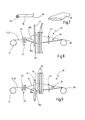
- FIGS. 8 and 9 schematically a loom 40 for the production of the textile part 10 is shown.
- the weaving machine 40 has a coating tree 41, via which the warp threads 17, 27 are fed.
- the warp threads 17, 27 initially pass through a warp stop 42 and fins 43.
- a plurality of heddle shafts, each with a plurality of heddles are arranged, which can be moved in the vertical direction for opening a tray up and down.
- the loom 40 is equipped in this embodiment with a leno system for producing a leno weave in the binding system 25.
- conventional strands and heddle shafts can be used.
- the upright warp threads 36b are guided by the healds in a first heald 44.
- the leno warp threads 36a are guided in a leno weaving harness in a second heald 45.
- Such a leno system is for example in EP 2 063 007 A1 described, to which reference is made. There are Halbcarderitatien generated. However, leno harnesses can also be used to make full turn bindings.
- each of the third healds 46 a portion of the reinforcing warp threads 17 is guided, which is the sake of clarity in the schematic representations according to the FIGS. 8 and 9 is not illustrated in detail.
- the strands for use in the third healds 46 for guiding the reinforcing warp threads 17 may be, for example, as in FIG EP 1 795 636 A1 be designed described.
- the warp threads 17, 36a, 36b pass through a reed 47 provided on a textile edge for abutment of a weft thread 16, 26.
- the textile material produced is taken up or wound up by a fabric take-off 48.
- the heald frames 44, 45, 46 at a weft insertion in a predetermined specialist position, for example in the upper compartment or in the lower compartment.
- a first section 20 is to be produced with a plain weave in the reinforcement system 15
- every second reinforcing warp thread 17 extending through this first section 20 is in the upper shed and the reinforcing warp threads 17 located therebetween in the weft direction S are in the lower shed.
- the reinforcing warp yarns 17 change the shed.
- the first weaving shank 44 positions the upright warp threads 36b in the upper sheath, for example.
- the leno warp yarns 36a and the reinforcing warp yarns 17 are positioned over the other healds 45, 46 in the lower shed ( FIG. 8 ).
- the leno weaving harnesses in the second heald 45 produce the crossing points in front of and / or behind the binding weft thread 26.
- First sections 20 and second sections 21 may alternate in the warp direction K and / or in the weft direction S or join each other.
- first and second sections 20, 21 in any desired sequence and combination both in the warp direction K and in the weft direction S is particularly simple with a jacquard weaving machine.
- a plate-shaped Composite element 11 are produced, as exemplified in FIG. 10 is illustrated.
- the textile part 10 is unwound as a textile tape to form the textile layer 13 from a first roller 50.
- a plastic film 52 can be supplied for the production of the composite material.
- the textile layer 13 and the plastic film 52 for example, fed to a double belt press 53 and connected there under the action of pressure and / or heat to form a composite material.
- the textile layer 13 and the plastic film 52 can be placed in front of the double belt press between two protective layers 54, which are removed after passing through the double belt press 53, as indicated by the two arrows P is illustrated.
- the composite can be trimmed in a station 55 and cut to length in a subsequent cutting station 56 in the desired length.
- plate-shaped composite elements 11 are produced, which can also be referred to as organic sheets.
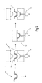
- FIG. 11 schematically illustrates the transformation of a plate-shaped composite element 11 to a three-dimensional composite body 12.
- the composite element 11 is first heated in a heating station 60.
- the composite element 11 is fed to a forming device 61, for example a press, and brought into the desired shape via forming tools.
- This forming process can also be carried out in stages in several press stages.
- the composite material becomes cooled and finally removed after cooling as a composite body 12.
- the at least one textile part 10 can also initially be draped into the desired three-dimensional shape, whereby a so-called preform 62 is created.
- the reshaped textile part 10 or the preform 62 can be fixed, for example, by the activation of the hot-melt adhesive properties of the binding yarns 28 in the binding system 25 and / or by an additional binder.
- the preform 62 can then be inserted into a mold 63. After closing this mold 63 flowable plastic, such as resin, is introduced into the mold 63.
- a differential pressure is generated, for example by the air from the mold 63 is sucked or the flowable plastic is pressurized and pressed or injected into the mold.
- FIG. 12 schematically and exemplarily a valve 64 is shown, which controls the injection of the plastic into the mold 63.
- the plastic hardens and forms the plastic matrix of the composite element 11 or the composite body 12.
- the plastic in the mold can be pressurized.
- the mold 63 is opened and the finished composite body 12 can be removed. This process is also referred to as "resin transfer molding".
- the present invention relates to a textile part 10 which is provided and configured in particular for the production of a composite element 11 or a composite body 12.
- the textile part 10 comprises a reinforcing system 15 of reinforcing warp yarns 16 and reinforcing weft yarns 17 made of a reinforcing yarn 18.
- the binding threads 26, 27 are made of a twine 28.
- the reinforcement system 15 has at least one first portion 20, in which the reinforcing threads 16, 17 are directly interwoven and therefore form a binding. This leads to a high mechanical strength of the composite material in the region in which the at least one first section 20 of the textile part 10 is arranged.
- the reinforcing system 15 also has at least one second section 21 into which the reinforcing threads 16, 17 form binding-free crossing points 22 and are preferably laid out in a stretched manner.
- the connection system 15 thus constitutes a scrim in the at least one second section 21. This scrim is bordered by the binding threads 26, 27 of the binding system 25.
- the binding warp threads 27 with the binding weft threads 26 in the at least one second section 21 form binding points 35, where they pass through the reinforcing system 15.
- a particularly good drapability and formability is ensured in this area.
- the reinforcing threads 16, 17 extending in this second section lead to good mechanical in-plane properties.
Landscapes
- Engineering & Computer Science (AREA)
- Textile Engineering (AREA)
- Mechanical Engineering (AREA)
- Chemical & Material Sciences (AREA)
- Composite Materials (AREA)
- Manufacturing & Machinery (AREA)
- Woven Fabrics (AREA)
- Diaphragms For Electromechanical Transducers (AREA)
Abstract
Description
- Die Erfindung betrifft ein Textilteil, ein Verbundwerkstoffelement mit einem solchen Textilteil sowie Verfahren zur Herstellung des Textilteils sowie des Verbundwerkstoffelements. Das Textilteil ist zum Einsatz in Verbundwerkstoffen vorgesehen, die auch als Composites bezeichnet werden. Solche textilverstärkten Verbundwerkstoffe sind grundsätzlich bekannt.
- In konventionell gewebten Textilteilen entsteht durch die Bindung der Kettfäden mit den Schussfäden eine Fadenwellung, so dass bei der Verwendung des Textilteils in einem Verbundwerkstoffelement eine nicht ideal gestreckte Ausrichtung der Fäden vorliegt. Das zur Verstärkung des Verbundwerkstoffs dienende, eine Textillage bildende Textilteil weist somit gewellte Fäden auf. Die erreichbare Festigkeit des Verbundwerkstoffelements ist deswegen nicht optimal. Knicke, Wellen oder kleine Radien sollten deswegen möglichst vermieden werden.
- Durch Vergrößerung der Abstände zwischen den Bindungsstellen kann zwar die Anzahl und Höhe der Wellen im betreffenden Faden verringert werden. Dies bedeutet, dass größere Flottierungen vorgesehen werden, was auch die Drapierfähigkeit des Textilteils erhöht. Allerdings entsteht dadurch bei extrem großen Flottierungen der Nachteil, dass unerwünschte Verschiebungen der Fäden des Texteilteils beim Drapieren und insbesondere beim Formen des Textilteils zu einem dreidimensionalen Verbundwerkstoffkörper entstehen können. Die Fadendichte kann dadurch an einigen Stellen unzureichend klein sein, während sie an anderen Stellen zu groß ist.
- Anstelle von Geweben können auch Gelege von Verstärkungsfäden als Textilteil verwendet werden. Bei diesen Gelegen ist es jedoch erforderlich, die Verstärkungsfäden durch ein zusätzliches Mittel miteinander zu fixieren. Nachteilig ist bei solchen Gelegen allerdings, dass sich einige mechanische Laminateigenschaften z.B. senkrecht zur Erstreckungsebene des Textilteils verschlechtern, etwa die Schubeigenschaft, die Lochleibungseigenschaft, die Schlagbeanspruchung oder die schädigungsfreie mechanische Bearbeitbarkeit des Textilteils bzw. des damit hergestellten Verbundwerkstoffelements. Da die typische webtechnische Bindung zwischen den Fäden des Textilteils fehlt, sind die mechanischen Eigenschaften senkrecht zur Erstreckungsebene häufig nicht ausreichend.
- Ein weiterer Aspekt bei der Ausgestaltung und der Herstellung und Verarbeitung eines Textilteils, insbesondere der Herstellung eines Verbundwerkstoffelements ist die Drapierfähigkeit bei einem Umformprozess. Dabei können Verbundwerkstoffelemente erhitzt und mechanisch umgeformt werden. Durch Spritzpressen ist es auch möglich, einen sogenannten Vorformling - auch Preform genannt - aus dem in die gewünschte Form gebrachten Textilteil zu bilden und beispielsweise durch Einspritzen von flüssigem Harz unter hohem Druck einen Verbundwerkstoffkörper herzustellen. Beim Umformen eines Verbundwerkstoffelements oder beim Drapieren eines Textilteils ist es unerwünscht, wenn die Fäden oder Fasern unkontrolliert fließen und sich verschieben. Ein Gelege hat bei diesem Verfahren den Vorteil, dass es zwar sehr drapierfähig ist, jedoch besteht bei einem Gelege die Gefahr, dass die Mittel zur Bindung des Geleges nicht ausreichend fest sind und damit die gewünschte Fadendichte in bestimmten Bereichen verloren geht. Auf der anderen Seite sind Gewebe weniger drapierfähig und daher schwerer umzuformen.
- Aus
US 4 320 160 ist ein Textilteil für Verbundwerkstoffkörper bekannt. Dieses Textilteil weist ein Verstärkungssystem aus aneinander gelegten Verstärkungsfäden auf, die über Bindefäden miteinander verbunden sind. Als Bindefäden werden Bindekettfäden und Bindeschussfäden durch einfache Schussfäden miteinander verbunden oder die Bindekettfäden gehen mit den Verstärkungskettfäden bzw. den Verstärkungsschussfäden eine Bindung ein. Dieses Textilteil hat den Nachteil, dass aufgrund der vorgeschlagenen Bindungsarten die Fadenspannung der Bindefäden klein sein muss, um eine unerwünschte Welligkeit der Verstärkungsfäden zu vermeiden. Dies führt wiederum dazu, dass keine ausreichende Verschiebefestigkeit der Verstärkungsfäden gewährleistet ist. Wird die erforderliche Verschiebefestigkeit erreicht, verursacht die Fadenspannung der Bindefäden zum einen eine Wellung der Verstärkungsfäden und zum anderen besteht die Gefahr, dass die Verstärkungsfäden durch die große Fadenspannung des Bindefadens zwischen den Bindungspunkten gebündelt und einer unerwünschte Struktur mit sehr ungleicher Fadendichte der Verstärkungsfäden entsteht. - Auch die
DE 20 2005 014 801 U1 offenbart ein Textilteil mit einem Verstärkungssystem aus Verstärkungsfäden und einem Bindungssystem aus Bindefäden zur Bindung des Verstärkungssystems, was dieselben Nachteile mit sich bringt, die im Zusammenhang mitUS 4 320 160 beschrieben wurden. -
DE 10 2005 022 567 A1 beschreibt ein textiles Flächengebilde, das bei einem beschriebenen Ausführungsbeispiel sowohl Dreher-, als auch Leinwandbindungen zwischen den Verstärkungsfäden aufweist. Beispielsweise kann immer nach einer vorgegebenen Anzahl von Leinwandbindungen eine Dreherbindung vorgesehen sein. - Ausgehend hiervon kann es als eine Aufgabe der vorliegenden Erfindung angesehen werden, ein Textilteil, ein Verbundwerkstoffelement mit einem solchen Textilteil sowie Herstellungsverfahren zu schaffen, wobei zum einen eine gute Handhabbarkeit bei der Formgebung oder Umformung des Textilteils bzw. des Verbundwerkstoffelements gewährleistet ist und zum anderen eine ausreichende mechanische Stabilität besteht.
- Diese Aufgabe wird durch ein Textilteil mit den Merkmalen des Patentanspruches 1, ein Verbundwerkstoffelement mit den Merkmalen des Patentanspruches 11, ein Verfahren zur Herstellung eines Textilteils mit den Merkmalen des Patentanspruches 12 sowie ein Verfahren zur Herstellung eines Verbundwerkstoffelements mit den Merkmalen des Patentanspruches 13 gelöst.
- Das erfindungsgemäße Textilteil weist ein Verstärkungssystem aus Verstärkungsschussfäden und Verstärkungskettfäden auf. Ferner ist bei einer erfindungsgemäßen Variante ein Bindungssystem aus Bindeschussfäden und Bindekettfäden vorhanden. Das Verstärkungssystem bildet in wenigstens einem ersten Abschnitt ein Gewebe mit einer herkömmlichen Bindung zwischen den Verstärkungsschussfäden und den Verstärkungskettfäden, beispielsweise eine Leinwandbindung, eine Köperbindung, eine Atlasbindung, eine Dreherbindung oder dergleichen.
- Das Textilteil weist außerdem wenigstens einen zweiten Abschnitt auf, in dem die Verstärkungsschussfäden und die Verstärkungskettfäden ohne unmittelbare Bindung aneinander anliegen. In diesem zweiten Abschnitt verlaufen die Verstärkungskettfäden und die Verstärkungsschussfäden gestreckt.
- Zur Fixierung der Verstärkungsfäden im zweiten Abschnitt kann dieser bei einer ersten erfindungsgemäßen Variante an mehreren Seiten in Kettfadenrichtung und/oder in Schussfadenrichtung, beispielsweise an zwei in Kettfadenrichtung gegenüberliegenden Seiten oder an zwei in Schussfadenrichtung gegenüberliegenden Seiten, durch einen oder jeweils einen ersten Abschnitt begrenzt und dadurch stabilisiert oder fixiert sein. Eine besonders gute Fixierung oder Stabilisierung ist erreicht, wenn dieser zweite Abschnitt ringsum an allen vier Seiten durch einen oder mehrere erste Abschnitte begrenzt ist.
- Bei einer zweiten erfindungsgemäßen Variante, die alternativ oder zusätzlich zu der ersten Variante realisiert werden kann, ist ein Bindungssystem vorhanden. Die Verstärkungsfäden werden durch das Bindungssystem gehalten, indem die Bindeschussfäden und die Bindkettfäden das Verstärkungssystem von entgegengesetzten Seiten einfassen, die an Bindungsstellen miteinander und/oder mit dem Verstärkungssystem eine Bindung herstellen.
- Sowohl der erste als auch der zweite Abschnitt weisen vorzugsweise jeweils mehrere nebeneinander angeordnete Verstärkungskettfäden und jeweils mehrere nebeneinander angeordnete Verstärkungsschussfäden auf, so dass beide Abschnitte flächig ausgestaltet sind.
- Durch die erfindungsgemäße Ausgestaltung des Textilteils entstehen Bereiche mit großer Drapierfähigkeit, in denen die Verstärkungsfäden des Verstärkungssystems ein Gelege bilden und durch die angrenzenden ersten Abschnitte des Textilteils und/oder durch das Bindungssystem gegen unerwünschte Verschiebungen gesichert werden. Das Gelege von Verstärkungsfäden in dem wenigstens eine zweiten Abschnitt und das Gewebe von Verstärkungsfäden in dem wenigstens einen ersten Abschnitt sind beim unverformten Textilteil in einer Erstreckungsebene nebeneinander angeordnet. Die Erstreckungsebene ist durch die Kettfadenrichtung und die Schussfadenrichtung definiert.
- Vorzugsweise sind die Bindungsstellen des Bindungssystems, sofern es vorhanden ist, zumindest in diesem zweiten Abschnitt durch eine Dreherbindung gebildet, beispielsweise eine Halbdreherbindung oder eine Volldreherbindung. In dem wenigstens einen ersten Abschnitt des Textilteils stehen die Verstärkungsfäden des Verstärkungssystems unmittelbar miteinander in einer webtechnischen Bindung und bilden ein Gewebe. In diesem ersten Abschnitt sind die Verstärkungsfäden gut gegen ein Verschieben gesichert und das Textilteil weist auch eine hohe mechanische Stabilität senkrecht zur Textilteilebene auf. Die Bindeschussfäden sowie die Bindekettfäden können in diesem ersten Abschnitt beispielsweise ohne Seitenwechsel auf einer Seite des Verstärkungssystems verlaufen. Alternativ kann das Bindungssystem das Verstärkungssystem im ersten Abschnitt zusätzlich einfassen und fixieren.
- Dieses erfindungsgemäße Textilteil eignet sich besonders zur Herstellung von insbesondere plattenförmigen Verbundwerkstoffelementen oder dreidimensional geformten Verbundwerkstoffkörpern. Ein solches Verbundwerkstoffelement bzw. ein solcher Verbundwerkstoffkörper weist angepasst an die Verwendung im Bereich der ersten Abschnitte des Textilteils eine sehr hohe mechanische Festigkeit auch senkrecht zur Fläche des Verbundwerkstoffelements auf. In dem wenigstens einen Bereich, in denen der Verbundwerkstoff umgeformt werden soll oder umgeformt ist, ist der wenigstens eine zweite Abschnitt des Textilteils angeordnet. Die hohe Drapierfähigkeit in diesem Bereich erlaubt eine einfache Umformbarkeit. Das Verstärkungssystem kann in diesem zweiten Abschnitt durch das Bindungssystem gegen Verrutschen der Verstärkungsfäden gesichert sein. Zusätzlich oder alternativ kann das Textilteil mehrere diesen zweiten Abschnitt umgebende erste Abschnitte aufweisen. Dadurch kann eine zusätzliche Einschränkung der Verschiebung der Verstärkungsfäden im zweiten Bereich erreicht werden. Die Verstärkungsfäden im zweiten Bereich sind mithin durch das Bindungssystem und/oder durch die Gewebebildung der Verstärkungsfäden in dem angrenzenden ersten Abschnitt gesichert. Das Textilteil lässt sich einfach durch das Positionieren des wenigstens einen ersten Abschnitts und des wenigstens einen zweiten Abschnitts an die Anforderungen im Verbundwerkstoff anpassen.
- Vorzugsweise sind in dem zweiten Abschnitt Bindungsstellen vorhanden, an denen zwei unmittelbar benachbarte Kettfäden, beispielsweise zwei Bindekettfäden oder ein Bindekettfaden und ein Verstärkungskettfaden ein Kettfadenpaar aus einem Steherkettfaden und einem Dreherkettfaden bilden. Der Steherkettfaden und der Drehkettfaden kreuzen sich beispielsgemäß mehrfach und schließen einen Bindeschussfaden an der Bindungsstelle ein. Durch eine solche Voll- oder Halbdreherbindung werden die Verstärkungsfäden im zweiten Abschnitt besonders gut gegen ein versehentliches Verschieben beim Drapieren bzw. Umformen des Textilteils bzw. des Verbundwerkstoffelements gesichert.
- Vorzugsweise sind die Bindefäden, also die Bindekettfäden sowie die Bindeschussfäden, in dem wenigstens einen ersten Abschnitt nur auf einer Seite des Verstärkungssystems angeordnet, so dass sie das Verstärkungssystem nicht einfassen sondern von einer Seite her am Verstärkungssystem anliegen. Die Bindeschussfäden können stets nur auf einer Seite des Verstärkungssystems verlaufen oder beim Übergang von einem ersten Abschnitt zu einem zweiten Abschnitt die Seite wechseln.
- Es ist von Vorteil, wenn bei einer Dreherbindung im Bindungssystem die wenigstens eine Kreuzungsstelle zwischen dem Kettfadenpaar aus Steherkettfaden und Dreherkettfaden im zweiten Abschnitt des Textilteils unmittelbar an der Bindungsstelle mit dem Bindeschussfaden liegen. Da an der Bindungsstelle die Fäden des Bindungssystems zwischen den Fäden des Verstärkungssystems hindurch greifen, also das Verstärkungssystem sozusagen durchsetzen, kann der dort ohnehin notwendige Abstand zwischen den benachbarten Verstärkungskettfäden bzw. den benachbarten Verstärkungsschussfäden genutzt werden, um an dieser Stelle die wenigstens eine Überkreuzungsstelle des Steherkettfadens mit dem Drehkettfaden vorzusehen.
- Die Bindekettfäden verlaufen vorzugsweise kreuzungsfrei gegenüber den Verstärkungskettfäden. Alle Kettfäden verlaufen mithin parallel in einer Kettfadenrichtung. Die Bindeschussfäden verlaufen vorzugsweise kreuzungsfrei gegenüber den Verstärkungsschussfäden. Alle Schussfäden verlaufen mithin parallel in einer Schussfadenrichtung, die in etwa rechtwinklig zur Kettfadenrichtung orientiert ist. Daher kann das Textilteil sehr einfach auf einer herkömmlichen Webmaschine oder eine Jacquard-Webmaschine hergestellt werden.
- Bei einer bevorzugten Ausgestaltung des Textilteils ist die Anzahl der Kreuzungsstellen in dem wenigstens einen zweiten Abschnitt zwischen den Verstärkungskettfäden und den Verstärkungsschussfäden gleich groß oder größer als die Anzahl der Bindungsstellen des Bindungssystems in diesem wenigstens einen zweiten Abschnitt. Die Anzahl der Schussfäden pro Längeneinheit (Fadendichte) kann bei einem Ausführungsbeispiel zumindest in dem wenigstens einen zweiten Abschnitt für die Bindeschussfäden kleiner sein als für die Verstärkungsschussfäden. Bei der Verwendung einer Dreherbindung für das Bindungssystem kann die Anzahl der Bindekettfadenpaare aus Steherkettfaden und Drehkettfaden pro Längeneinheit maximal so groß sein, wie die Anzahl der Verstärkungskettfäden. Der Abstand der Bindungsstellen im Bindungssystem kann in Kettfadenrichtung und in Schussfadenrichtung unterschiedlich groß gewählt werden. Der Abstand der Bindungsstellen kann sowohl in Kettfadenrichtung, als auch in Schussfadenrichtung variieren, so dass sich Zonen mit dichter angeordneten Bindungsstellen und Zonen mit weniger dicht angeordneten Bindungsstellen bilden und daher die Verschiebungsfestigkeit der Verstärkungsfäden innerhalb des wenigstens einen zweiten Abschnitts von Zone zu Zone variiert. Wird eine höhere Drapierfähigkeit des wenigstens einen zweiten Abschnitts gewünscht, so kann die Größe bzw. Länge der Flottierung im Bindungssystem entsprechend vergrößert werden.
- Für die Verstärkungsschussfäden und die Verstärkungskettfäden wird insbesondere ein Verstärkungsgarn gewählt, dass sich vom Bindegarn, aus dem die Bindekettfäden und die Bindeschussfäden gemacht sind, unterscheidet. Für die mechanische Steifigkeit oder Festigkeit des Verbundwerkstoffelements, das mit Hilfe des Textilteils hergestellt ist, sind hauptsächlich die Verstärkungsfäden des Verstärkungssystems verantwortlich. Das Verstärkungsgarn kann beispielsweise Karbonfaser und/oder Aramidfasern und/oder Glasfasern aufweisen. Bei einem Ausführungsbeispiel können die Verstärkungsfäden einen Flachquerschnitt haben, dessen Breite in der Erstreckungsebene des Textilteils größer ist als des in Höhe quer zur Erstreckungsebene des Textilteils. Im Unterschied dazu kann der Querschnitt des Bindegarns vorzugsweise kreisrund gewählt werden. Der Titer oder der Querschnitt des Bindegarns ist insbesondere kleiner als der Titer oder der Querschnitt des Verstärkungsgarns. Der Titer des Verstärkungsgarns beträgt vorzugsweise mindestens 500 dtex. Der Titer des Bindegarns ist vorzugsweise kleiner als 500 dtex, insbesondere maximal 100 dtex und weiter vorzugsweise maximal 50 dtex. Dadurch lässt sich der Massenteil des Bindegarns gegenüber dem Verstärkungsgarn im Textilteil gering halten. Außerdem ist der Platzbedarf zwischen zwei benachbarten Verstärkungsfäden des Verstärkungssystems, den ein Bindeschussfaden oder ein Bindekettfaden beansprucht, gering. Die mechanische Belastbarkeit, insbesondere die Zugbelastbarkeit des Verstärkungsgarns für die Verstärkungsfäden ist größer als die Belastbarkeit des Bindegarns für die Bindefäden.
- Als Bindegarn kommen PES- oder Phenoxy-Garne in Betracht, wie etwa Grilon MS ® der Firma EMS Chemie. Es können auch andere Garne, insbesondere Schmelzklebegarne, verwendet werden, wie etwa Co-Polyester-Garne oder thermoplastische Garne, wie z.B. PA. Bevorzugt besteht das Bindegarn teilweise oder vollständig aus einem Kunststoff, der der Kunststoffmatrix des Verbundwerkstoffelements entspricht.
- Bei einer bevorzugten Ausführungsform wird für das Bindegarn ein Material eingesetzt, das sich bei der Herstellung des Verbundwerkstoffelements gut und im Wesentlichen vollständig mit dem Kunststoff des Verbundwerkstoffes verbindet. Das Material des Bindegarns kann abhängig von dem Kunststoff des Verbundwerkstoffes gewählt werden. Insbesondere enthält das Bindegarn ein Material, dessen Schmelztemperatur maximal so groß ist wie die Temperatur, die bei der Herstellung des Verbundwerkstoffelements bzw. des Verbundwerkstoffkörpers vorherrscht, so dass ein Verschmelzen zwischen dem Bindegarn und dem Kunststoff des Verbundwerkstoffes erfolgt.
- Vorzugsweise wird der Titer des Bindegarns derart festgelegt, dass die interlaminare Scherfestigkeit des herzustellenden Verbundwerkstoffes bzw. Verbundwerkstoffkörpers von einem durch das Verstärkungssystem vorgegebenen Sollwert maximal um einen vorgegebenen Toleranzwert abweicht. Beispielsweise kann der Massenanteil des Bindegarns im Bindungssystem so vorgegeben werden, dass die allein durch das Verstärkungssystem erreichte interlaminare Scherfestigkeit maximal um einen Toleranzwert von beispielsweise 5% abweicht. Dies kann insbesondere dann von Bedeutung sein, wenn sich das verwendete Bindegarn nicht oder nur schlecht mit dem Kunststoff des herzustellenden Verbundwerkstoffes verbinden kann.
- Bei einer vorteilhaften Ausführung weist das Bindegarn einen Kern und einem dem Kern umschließenden Mantel auf. Der Kern und der Mantel sind vorzugsweise aus unterschiedlichem Material hergestellt. Insbesondere ist die Schmelztemperatur des Mantels geringer als die Schmelztemperatur des Kerns. Der Mantel besteht vorzugsweise aus Kunststoff. Es können daher die Schmelzklebeeigenschaften des Bindegarns durch Schmelzen des Mantels aktiviert werden, ohne dass der Kern seine Stabilität oder Struktur verliert.
- Bei der Verwendung von Schmelzklebegarnen bzw. Garnen mit einem Kern oder einem Mantel mit unterschiedlichen Schmelztemperaturen ist eine einfache Herstellung von Vorformlingen gegeben. Das Textilteil kann in die gewünschte Form drapiert und anschließend können die Schmelzklebeeigenschaften des Bindegarns aktiviert werden, insbesondere durch Einwirkung von einer Strahlung, beispielsweise thermischer Strahlung. Die Verwendung von Bindemitteln zur Lagefixierung der Bindegarne in einer dreidimensionalen Gestalt des Textilteils ist alternativ oder zusätzlich möglich, kann aber bei Bindegarnen mit Schmelzklebeeigenschaft entfallen, da die Bindegarne bereits die Fixierungsfunktion übernehmen.
- Das Textilteil eignet sich insbesondere für die Verwendung zur Herstellung eines Verbundwerkstoffelements. Ein solches Verbundwerkstoffelement weist ein Textilteil auf, das eine Textillage bildet sowie eine Kunststoffmatrix, die mit der Textillage verbunden ist. Hierzu kann beispielsweise eine Kunststofffolie mit der Textillage verbunden werden, insbesondere durch thermische Einwirkung und/oder Druckeinwirkung. Das Verbundwerkstoffelement kann auch mehrere Textillagen aufweisen. Die Kunststoffmatrix kann durch Verbinden wenigstens einer Kunststofffolie mit dem wenigstens einen Textilteil oder durch Einbringen von fließfähigem Kunststoff in eine das Textilteil aufnehmende Form hergestellt sein. Beispielsweise kann das wenigstens eine Textilteil zunächst in die etwa dem späteren herzustellenden Verbundwerkstoffelement entsprechende Form drapiert werden. Gegebenenfalls werden dabei mehrere Textilteile geschichtet. Die Verstärkungsfäden werden in die gewünschte Richtung orientiert. Die so entstandene Preform kann zur Aufrechterhaltung ihrer Gestalt fixiert werden, beispielsweise mit einem Bindemittel oder durch Aktivieren des Schmelzklebeeigenschaft des Binde- und/oder des Verstärkungsgarns. Die Preform wird in eine Form eingelegt, in die anschließend fließfähiger Kunststoff bzw. Harz eingebracht wird. Nach dem Aushärten des Kunststoffes kann das Verbundwerkstoffelement aus der Form entnommen werden. Der wenigstens eine zweite Abschnitt mit dem Gelege der Verstärkungsfäden sorgt für eine gute Drapierfähigkeit, während der wenigstens eine erste Abschnitt mit den gewebten Verstärkungsfäden den wenigstens einen zweiten Abschnitt und/oder das Bindungssystem fixiert. Beim Einbringen des Kunststoffes in die Form wird ein versehentliches Verschieben oder Verrutschen der Verstärkungsfäden im wenigstens einen zweiten Abschnitt vermieden oder zumindest reduziert.
- Ein solches Textilteil lässt sich auf einer Webmaschine herstellen. Dabei werden Verstärkungsschussfäden und Bindeschussfäden in einer vorgegebenen Reihenfolge nacheinander eingetragen bzw. eingeschossen. Während des Schusseintrags mit einem Verstärkungsschussfaden befinden sich die Verstärkungskettfäden, die durch den wenigstens einen ersten Abschnitt verlaufen, abhängig von der Bindungsart im Oberfach oder im Unterfach. Die Verstärkungskettfäden, die durch einen wenigstens zweiten Abschnitt verlaufen, befinden sich stets in demselben Fach, entweder im Oberfach oder im Unterfach. Auf diese Weise wird im ersten Abschnitt ein Gewebe zwischen den Verstärkungsfäden und dem zweiten Abschnitt ein Gelege zwischen den Verstärkungsfäden erzeugt.
- Bei einem Schusseintrag mit einem Bindeschussfaden befinden sich die durch den wenigstens einen zweiten Abschnitt verlaufenden Verstärkungskettfäden jeweils in demselben Fach, entweder im Oberfach oder im Unterfach, während sich zumindest ein Teil der durch diesen zweiten Abschnitt verlaufenden Bindekettfäden im jeweils anderen Fach befindet. Dadurch wird im zweiten Abschnitt die Einfassung des Verstärkungssystems zwischen den Bindekettfäden und den Bindschussfäden erreicht.
- Weitere vorteilhafte Ausgestaltungen der Erfindung ergeben sich aus den abhängigen Patentansprüchen sowie der Beschreibung. Die Beschreibung beschränkt sich auf wesentliche Merkmale der Erfindung. Die Zeichnung ist ergänzend heranzuziehen. Nachfolgend werden Ausführungsbeispiele der Erfindung anhand der beigefügten Zeichnung erläutert. Es zeigen:
-
Figuren 1 bis 4 jeweils ein Ausführungsbeispiel eines ersten Abschnitts sowie eines zweiten Abschnitts eines Textilteils in schematischer Draufsicht, -
Figur 5 die schematische Darstellung einer Bindungsstelle zwischen Bindeschussfaden und Bindekettfaden im Bindungssystem in schematischer Draufsicht, -
Figur 6 die Bindungsstelle nachFigur 5 in einem Schnittbild durch das Textilteil gemäß Schnittlinie VI-VI, -
Figur 7 eine Prinzipdarstellung eines Bindegarns für die Bindefäden und eines Verstärkungsgarns für die Verstärkungsfäden, -
Figur 8 eine schematische, blockschaltbildähnliche Darstellung eines Webmaschine während des Eintrags eines Bindeschussfadens, -
Figur 9 die Webmaschine nachFigur 8 während des Eintrags eines Verstärkungsschussfadens, -
Figur 10 , eine schematische, blockschaltbindähnliche Darstellung der Herstellung eines Verbundwerkstoffelements in Plattenform, -
Figur 11 eine Variante der Herstellung eines Verbundwerkstoffkörpers aus einem Verbundwerkstoffelement in stark schematisierter blockschaltbildähnlicher Darstellung und -
Figur 12 eine weitere Variante der Herstellung eines Verbundwerkstoffkörpers in stark schematisierter blockschaltbildähnlicher Darstellung. - In den
Figuren 1 bis 4 ist jeweils äußerst schematisch der Aufbau eines Texteilteils 10 veranschaulicht. Das Textilteil 10 dient insbesondere zur Herstellung eines Verbundwerkstoffelements 11 oder eines Verbundwerkstoffkörpers 12 mit einer Textillage 13, die durch ein Textilteil 10 gebildet ist. - Das Textilteil 10 weist ein Verstärkungssystem 15 mit Verstärkungsschussfäden 16 und Verstärkungskettfäden 17 auf, die aus einem Verstärkungsgarn 18 hergestellt sind. Das Verstärkungsgarn 18 ist schematisch in
Figur 7 veranschaulicht und weist einen Flachquerschnitt mit ovaler oder ellipsenähnlicher Kontur auf. Durch das Verstärkungsgarn 18 erhält der das Textilteil 10 aufweisende Verbundwerkstoffkörper 12 bzw. das das Textilteil 10 aufweisende Verbundwerkstoffelement 11 die gewünschte mechanischen Eigenschaften, wie etwa die gewünschte mechanische Festigkeit und Steifigkeit. Das Verstärkungsgarn 18 könnte anstelle eines Flachquerschnitts auch einen im Wesentlichen kreisförmigen Querschnitt aufweisen. - Das Verstärkungsgarn 18 kann Kohlefasern, Aramidfasern oder Glasfasern aufweisen oder aus derartigen Fasern bestehen. Es ist alternativ auch möglich, das Verstärkungsgarn 18 als sogenanntes Roving auszuführen, bei dem eine Vielzahl von einzelnen Fasern ungedreht parallel zueinander angeordnet sind.
- Die aus dem Verstärkungsgarn 18 bestehenden Verstärkungskettfäden 17 sowie die Verstärkungsschussfäden 16 bilden in wenigstens einem ersten Abschnitt 20 des Textilteils 10 ein Gewebe und in wenigstens einem zweiten Abschnitt 21 des Textilteils 10 ein Gelege. Die Verstärkungsschussfäden 16 und die Verstärkungskettfäden 17, die durch den ersten Abschnitt 20 verlaufen, sind unmittelbar miteinander verwoben, vorzugsweise in einer üblichen Bindung, wie Leinwandbindung, Köperbindung, Atlasbindung oder Dreherbindung. In den
Figuren 1 bis 4 ist beispielhaft eine Leinwandbindung im ersten Abschnitt 20 veranschaulicht. In dem zweiten Abschnitt 21 verlaufen sowohl die Verstärkungsschussfäden, als auch die Verstärkungskettfäden 17 gestreckt und stehen miteinander in keiner unmittelbaren Bindung. Die Verstärkungsschussfäden 16 liegen an den Verstärkungskettfäden 17 im zweiten Abschnitt 21 an. Die Verstärkungsfäden 16, 17 bilden im Abschnitt 21 bindungsfreie Kreuzungsstellen 22. Der Abstand zwischen benachbarten Verstärkungsschussfäden 16 und der Abstand zwischen benachbarten Verstärkungskettfäden 17 hängt sowohl im ersten Abschnitt 20, als auch im zweiten Abschnitt 21 von den gewünschten mechanischen Eigenschaften des mit Hilfe des Textilteils 10 hergestellten Verbundwerkstoffelements 11 ab. - Die Anzahl der ersten Abschnitte 20 und der zweiten Abschnitte 21 des Textilteils 10 kann beliebig sein. Die Anordnung und Anzahl der vorhandenen ersten Abschnitte 20 und zweiten Abschnitte 21 wird so gewählt, dass das damit hergestellte Verbundwerkstoffelement 11 bzw. der damit hergestellte Verbundwerkstoffkörper 12 Zonen mit hoher mechanischer Festigkeit in Bezug auf die webtypische Bindung und Zonen mit hoher Drapierbarkeit und den mechanischen Eigenschaften in der Erstreckungsebene der Verstärkungsfäden ("In-Plane-Eigenschaften") aufweist. In den Zonen mit hoher Drapierbarkeit weist das Textilteil 10 einen zweiten Abschnitt 21 auf, während es in Zonen mit hoher mechanischer Festigkeit einen ersten Abschnitt 20 aufweist.
- Um beim Umformen des Textilteils 10 bei der Herstellung eines Vorformlings (auch Preform genannt) oder eines Verbundwerkstoffelements oder auch beim Umformen eines mit Hilfe des Textilteils 10 hergestellten Verbundswerkstoffelements 11 ein unerwünscht starkes Verschieben der Verstärkungsfäden 16, 17 in dem wenigstens einen zweiten Abschnitt 21 zu vermeiden, weist das Textilteil 10 beispielsgemäß ein Bindungssystem 25 auf.
- Bei einer alternativen nicht dargestellten Variante können die Verstärkungsfäden 16, 17 in dem wenigstens einen zweiten Abschnitt 21 allein oder zusätzlich zu dem Bindungssystem 25 durch den wenigstens einen angrenzenden ersten Abschnitt 20 gegen ein Verschieben gesichert sein. Dabei grenzt beispielsweise an den zweiten Abschnitt 21 von mehreren Seiten in der Erstreckungsebene des Textilteils 10 der wenigstens eine erste Abschnitt 20 an. Die Erstreckungsebene des Textilteils 10 ist durch die Kettfadenrichtung K und/oder Schussfadenrichtung S definiert. Nach dem Umformen des Textilteils 10 kann aus der Erstreckungsebene eine gekrümmte Fläche werden.
- Das Bindungssystem 25 enthält Bindeschussfäden 26 und Bindekettfäden 27. Die Bindefäden 26, 27 sind aus einem Bindegarn 28 hergestellt, wobei ein Ausführungsbeispiel des Bindegarns mit einem Kern 29 und einem Mantel 30 in
Figur 7 veranschaulicht ist. Das Bindegarn hat beim Ausführungsbeispiel einen im Wesentlichen kreisrunden Querschnitt. Dieser Querschnitt ist kleiner als der Querschnitt des Verstärkungsgarns 18. Das Bindegarn hat vorzugsweise einen Titer von kleiner als 500 dtex, insbesondere maximal 100 dtex oder maximal 50 dtex. Bei der inFigur 7 dargestellten Ausführungsform hat das Bindegarn 28 Schmelzklebeeigenschaften, die beispielsgemäß durch den Mantel 30 erhalten werden. Der Mantel 30 umschließt den Kern 29 koaxial. Die Schmelztemperatur des Mantels 30 ist kleiner als die Schmelztemperatur des Kerns 29. Bei der Herstellung des Verbundswerkstoffelements 11 bzw. des Verbundwerkstoffkörpers 12 werden die Schmelzklebeeigenschaften des Mantels 30 und mithin des Bindegarns 28 aktiviert, wodurch eine Fixierung der Bindegarne 28 mit den Verstärkungsgarnen 18 des Textilteils 10 erreicht wird. Dadurch ist es auch möglich, vor der Herstellung eines Verbundswerkstoffs das Textilteil 10 in eine gewünschte dreidimensionale Form zu bringen und einen Vorformling bzw. eine Preform herzustellen. - Sowohl die Bindekettfäden 27, als auch die Verstärkungskettfäden 17 verlaufen in einer Kettfadenrichtung K und beim Ausführungsbeispiel kreuzungsfrei nebeneinander. Die Verstärkungsschussfäden 16 und die Bindeschussfäden 26 verlaufen in einer Schussfadenrichtung S und beim Ausführungsbeispiel kreuzungsfrei nebeneinander.
- Zumindest in dem wenigstens einen zweiten Abschnitt 21 des Textilteils 10 fassen die Bindekettfäden 27 und die Bindeschussfäden 26 das Verstärkungssystem 15 ein, um die Verstärkungsfäden 16, 17 in diesem zweiten Abschnitt 21 gegen ein versehentliches Verschieben zu sichern. Dabei verlaufen die Bindeschussfäden 26 auf einer Seite des Verbindungssystems 15, während die Bindekettfäden 27 auf der jeweils anderen Seite des Verstärkungssystems 15 angeordnet sind. An Bindungsstellen 35 sind die Bindeschussfäden 26 mit den Bindekettfäden 27 durch eine gewebte Bindung verbunden. Das Gelege aus Verstärkungsschussfäden 16 und Verstärkungskettfäden 17 im zweiten Abschnitt 21 wird dadurch gegen zu große Bewegungen in Kettfadenrichtung K oder Schussfadenrichtung S gesichert.
- Bei einem Ausführungsbeispiel nach
Figur 4 ist zwischen einem Bindekettfaden 27 und einem Bindeschussfaden 26 an einer Bindungsstelle 35 eine einfache Bindung vorgesehen. Der Bindekettfaden 27 übergreift den Bindeschussfaden 26 an der Bindungsstelle 35. Bei den in denFiguren 1 bis 3 dargestellten Ausführungsformen ist eine Volldreherbindung oder eine Halbdreherbindung an die Bindungsstellen 35 des Bindungssystems 25 vorgesehen. Hierfür verlaufen vorzugsweise jeweils zwei Bindekettfäden 27 unmittelbar benachbart zwischen zwei Verstärkungskettfäden 17. Dieses Kettfadenpaar 36 weist einen Dreherkettfaden 36a und einen Steherkettfaden 36b auf, die von jeweils einem Bindekettfaden 27 gebildet sind. An der Bindungsstelle 35 verläuft der Bindeschussfaden 26 zwischen dem Dreherkettfaden 36a und dem Steherkettfaden 36b. Dadurch ergibt sich eine gute Fixierung im Bindungssystem 25 und mithin auch im Verstärkungssystem 15 im zweiten Abschnitt 21. Diese Verschiebefestigkeit kann durch eine geringe Fadenspannung im Bindungssystem 25 erreicht werden. Eine Welligkeit der Verstärkungsfäden 16, 17 im zweiten Abschnitt 21 ist dadurch vermieden. - Ein Ausführungsbeispiel für eine Dreherbindung an der Bindungsstelle 35 ist in den
Figuren 5 und 6 schematisch dargestellt. Dabei kreuzen sich der Dreherkettfaden 36a und der Steherkettfaden 36b an einer Bindungsstelle 35 einmal unmittelbar vor dem Bindeschussfaden 26 und ein weiteres Mal unmittelbar hinter dem Bindeschussfaden 26 in Kettfadenrichtung K gesehen. An dieser Bindungsstelle ist ein möglichst kleiner Freiraum zwischen den beiden benachbarten Verstärkungsschussfäden 16 und den beiden benachbarten Verstärkungskettfäden 17 vorhanden, so dass durch die Fadenkreuzungen im Bindungssystem 25 an der Bindungsstelle 35 keine Fadenwelligkeit im Verstärkungssystem 15 erzeugt wird. - Anstelle der in den
Figuren 5 und 6 dargestellten Dreherbindung können auch andere Bindungsarten im Bindungssystem 25 verwendet werden. Als Steherkettfaden 36b kann alternativ zu den dargestellten Ausführungsbeispielen auch ein Verstärkungskettfaden dienen. - Bei den Ausführungsbeispielen gemäß der
Figuren 1 und4 fasst das Bindungssystem 25 das Verstärkungssystem 15 auch in dem wenigstens einen ersten Abschnitt 20 ein. Dies kann bspw. bei der Herstellung eines Vorformlings aus dem Textilteil 10 vorteilhaft sein, um unerwünschte Relativverschiebungen zwischen dem Bindungssystem 25 und dem Verstärkungssystem 15 auch in dem wenigstens einen ersten Abschnitt 20 zumindest zu reduzieren. Bei den Ausführungsbeispielen nachFiguren 2 und3 liegt das Bindungssystem 25 und mithin sowohl die Bindeschussfäden 26, als auch die Bindekettfäden 27 in dem ersten Abschnitt 20 lediglich auf einer Seite des Verstärkungssystems 15 an, ohne dieses einzufassen. Für die Fixierung der Verstärkungskettfäden 17 mit den Verstärkungsschussfäden 16 in dem wenigstens einen ersten Abschnitt 20 ist das Bindungssystem 25 nicht erforderlich. - In den
Figuren 8 und 9 ist schematisch eine Webmaschine 40 zur Herstellung des Textilteils 10 dargestellt. Die Webmaschine 40 weist einen Streichbaum 41 auf, über den die Kettfäden 17, 27 zugeführt werden. Die Kettfäden 17, 27 verlaufen zunächst durch einen Kettfadenwächter 42 und Lamellen 43. Anschließend sind mehrere Webschäfte mit jeweils einer Vielzahl von Weblitzen angeordnet, die in Vertikalrichtung zur Öffnung eines Fachs auf und ab bewegt werden können. Die Webmaschine 40 ist bei diesem Ausführungsbeispiel mit einem Drehersystem zur Herstellung einer Dreherbindung im Bindungssystem 25 ausgestattet. Für eine alternativ einsetzbare einfachere webtechnische Bindung können übliche Litzen und Webschäfte verwendet werden. - Die Steherkettfäden 36b sind durch die Weblitzen in einem ersten Webschaft 44 geführt. Die Dreherkettfäden 36a sind in einem Dreherwebgeschirr in einem zweiten Webschaft 45 geführt. Ein solches Drehersystem ist zum Beispiel in
EP 2 063 007 A1 beschrieben, auf das insoweit Bezug genommen wird. Dort werden Halbdreherbindungen erzeugt. Es können jedoch auch Dreherwebgeschirre verwendet werden, um Volldreherbindungen herzustellen. - Abhängig von der Art der Bindung zwischen den Verstärkungskettfäden 17 und den Verstärkungsschussfäden 16 in wenigstens einen ersten Abschnitt 20 sind mehrere dritte Webschäfte 4 vorhanden. Durch die Litzen in jedem der dritten Webschäfte 46 wird ein Teil der Verstärkungskettfäden 17 geführt, was der Übersicht wegen in den schematischen Darstellungen gemäß der
Figuren 8 und 9 nicht im Einzelnen veranschaulicht ist. Die Litzen zur Verwendung in den dritten Webschäften 46 zur Führung der Verstärkungskettfäden 17 können beispielsweise wie inEP 1 795 636 A1 beschrieben ausgestaltet sein. - Im Anschluss an die Webschäfte 44, 45, 46 verlaufen die Kettfäden 17, 36a, 36b durch ein zum Anschlag eines eingetragenen Schussfadens 16, 26 an einer Textilkante vorhandenes Riet 47. Das hergestellte Textilmaterial wird durch einen Warenabzug 48 aufgenommen bzw. aufgewickelt.
- Bei der Herstellung des Textilteils 10 befinden sich die Webschäfte 44, 45, 46 bei einem Schusseintrag in einer vorgegebenen Fachstellung, beispielsweise im Oberfach oder im Unterfach. Wenn im Verstärkungssystem 15 ein erster Abschnitt 20 mit einer Leinwandbindung hergestellt werden soll, befindet sich jeder zweite durch diesen ersten Abschnitt 20 verlaufende Verstärkungskettfaden 17 im Oberfach und die jeweils in Schussfadenrichtung S gesehen dazwischen befindlichen Verstärkungskettfäden 17 im Unterfach. Nach jedem Schusseintrag eines Verstärkungsschussfadens 16 wechseln die Verstärkungskettfäden 17 das Fach.
- Soll beim Eintrag eines Verstärkungsschussfaden 16 ein zweiter Abschnitt 21 erzeugt werden, verbleiben alle Verstärkungskettfäden 17, die durch diesen zweiten Abschnitt 21 hindurch verlaufen, entweder im Oberfach oder im Unterfach, je nach dem ob die Verstärkungsschussfäden 16 unterhalb oder oberhalb der Verstärkungskettfäden 17 abgelegt werden sollen.
- Zur Einfassung des Verstärkungssystems 15 in einem zweiten Abschnitt 21 oder auch in einem ersten Abschnitt 20 positioniert der erste Webschaft 44 die Steherkettfäden 36b beispielsgemäß im Oberfach. Die Dreherkettfäden 36a sowie die Verstärkungskettfäden 17 werden über die anderen Webschäfte 45, 46 im Unterfach positioniert (
Figur 8 ). Abhängig von der hergestellten Dreherbindung werden durch das Dreherwebgeschirr im zweiten Webschaft 45 die Kreuzungsstellen vor und/oder hinter dem Bindeschussfaden 26 erzeugt. - Erste Abschnitte 20 und zweite Abschnitte 21 können sich in Kettfadenrichtung K und/oder in Schussfadenrichtung S abwechseln beziehungsweise aneinander anschließen.
- Alternativ zu der schematischen Darstellung in den
Figuren 8 und 9 kann auch eine Jacquard-Webmaschine zur Herstellung des Textilteils 10 eingesetzt werden. In einer Jacquard-Webmaschine können über ansteuerbare Platinen alle Kettfäden 17, 27 einzeln in eine gewünschte Fachstellung gebracht werden, wodurch eine große Vielfalt an Bindungsarten herstellbar ist. Das Herstellen von ersten und zweiten Abschnitten 20, 21 in beliebiger Folge und Kombination sowohl in Kettfadenrichtung K als auch in Schussfadenrichtung S ist mit einer Jacquard-Webmaschine besonders einfach. - Mithilfe des Textilteils 10 kann ein plattenförmiges Verbundwerkstoffelement 11 hergestellt werden, wie dies beispielhaft in
Figur 10 veranschaulicht ist. Das Textilteil 10 wird als Textilband zur Bildung der Textillage 13 von einer ersten Rolle 50 abgewickelt. Über eine zweite Rolle 51 kann zur Herstellung des Verbundwerkstoffes eine Kunststofffolie 52 zugeführt werden. Die Textillage 13 und die Kunststofffolie 52 werden z.B. einer Doppelbandpresse 53 zugeführt und dort unter Einwirkung von Druck und/oder Wärme zu einem Verbundwerkstoff verbunden. Um ein Anhaften des Verbundwerkstoffes in den Werkzeugen der Doppelbandpresse 53 zu vermeiden, können die Textillage 13 und die Kunststofffolie 52 vor der Doppelbandpresse zwischen zwei Schutzlagen 54 angeordnet werden, die nach dem Durchlaufen der Doppelbandpresse 53 wieder entfernt werden, wie dies durch die beiden Pfeile P veranschaulicht ist. - Im Anschluss an die Doppelbandpresse 53 und das Entfernen der Schutzlagen 54 kann der Verbundwerkstoff in einer Station 55 besäumt und in einer anschließenden Schneidstation 56 in der gewünschten Länge abgelängt werden.
- Dadurch werden plattenförmige Verbundwerkstoffelemente 11 hergestellt, die auch als Organobleche bezeichnet werden können.
-
Figur 11 veranschaulicht schematisch die Umformung eines plattenförmigen Verbundwerkstoffelements 11 zu einem dreidimensionalen Verbundwerkstoffkörper 12. Das Verbundwerkstoffelement 11 wird zunächst in einer Heizstation 60 erwärmt. In diesem erwärmten Zustand wird das Verbundwerkstoffelement 11 einer Umformvorrichtung 61, beispielsweise einer Presse zugeführt und über Umformwerkzeuge in die gewünschte Form gebracht. Dieser Umformprozess kann auch gestuft in mehreren Pressenstufen durchgeführt werden. In dem gewünschten ungeformten Zustand wird das Verbundwerkstoffmaterial abgekühlt und nach der Abkühlung schließlich als Verbundwerkstoffkörper 12 entnommen. - Alternativ zu dieser geschilderten Vorgehensweise beim Herstellen eines Verbundwerkstoffkörpers 12 kann das wenigstens eine Textilteil 10 auch zunächst in die gewünschte dreidimensionale Form drapiert werden, wodurch eine sogenannte Preform 62 entsteht. Das umgeformte Textilteil 10 bzw. die Preform 62 kann fixiert werden, beispielsgemäß durch die Aktivierung der Schmelzklebeeigenschaften der Bindegarne 28 im Bindungssystem 25 und/oder durch ein zusätzliches Bindemittel. Wie in
Figur 12 veranschaulicht kann die Preform 62 anschließend in eine Form 63 eingelegt werden. Nach dem Schließen dieser Form 63 wird fließfähiger Kunststoff, beispielsweise Harz, in die Form 63 eingebracht. Um den Kunststoff in die Form 63 zu bringen, wird ein Differenzdruck erzeugt, beispielsweise indem die Luft aus der Form 63 gesaugt wird oder der fließfähige Kunststoff unter Druck gesetzt und in die Form gedrückt oder eingespritzt wird. InFigur 12 ist schematisch und beispielhaft ein Ventil 64 dargestellt, das das Einspritzen des Kunststoffs in die Form 63 steuert. - Bei geschlossener Form härtet der Kunststoff aus und bildet die Kunststoffmatrix des Verbundwerkstoffelements 11 bzw. des Verbundwerkstoffkörpers 12. Beim Aushärten kann der Kunststoff in der Form unter Druck gesetzt werden. Nach dem Aushärten wird die Form 63 geöffnet und der fertige Verbundwerkstoffkörper 12 kann entnommen werden. Dieses Verfahren wird auch als "Resin-Transfer-Molding" bezeichnet.
- Alternativ wäre es auch möglich, eine Preform 62 mit einer oder mehreren Kunststofffolien zu verbinden.
- Die vorliegende Erfindung betrifft ein Textilteil 10, das insbesondere für die Herstellung eine Verbundwerkstoffelements 11 oder eines Verbundwerkstoffkörpers 12 vorgesehen und ausgestaltet ist. Das Textilteil 10 weist ein Verstärkungssystem 15 aus Verstärkungskettfäden 16 und Verstärkungsschussfäden 17 auf, die aus einem Verstärkungsgarn 18 hergestellt sind. Ferner ist ein Bindungssystem 25 vorhanden, das aus Bindekettfäden 27 und Bindeschussfäden 26 besteht. Die Bindefäden 26, 27 sind aus einem Bindegarn 28 hergestellt. Das Verstärkungssystem 15 weist wenigstens einen ersten Abschnitt 20 auf, in den die Verstärkungsfäden 16, 17 unmittelbar miteinander verwoben sind und daher eine Bindung eingehen. Dies führt zu einer hohen mechanischen Belastbarkeit des Verbundwerkstoffes in dem Bereich, in dem der wenigstens eine erste Abschnitt 20 des Textilteils 10 angeordnet ist. Das Verstärkungssystem 15 weist außerdem wenigstens einen zweiten Abschnitt 21 auf, in den die Verstärkungsfäden 16, 17 bindungsfreie Kreuzungsstellen 22 bilden und vorzugsweise gestreckt aneinander gelegt sind. Das Verbindungssystem 15 stellt in dem wenigstens einen zweiten Abschnitt 21 somit ein Gelege dar. Dieses Gelege wird durch die Bindefäden 26, 27 des Bindungssystems 25 eingefasst. Hierfür bilden die Bindekettfäden 27 mit den Bindeschussfäden 26 in dem wenigstens einen zweiten Abschnitt 21 Bindungsstellen 35, an denen sie das Verstärkungssystem 15 durchgreifen. Durch das im zweiten Abschnitt 21 vorgesehene Gelege des Verstärkungssystems 15 ist in diesem Bereich eine besonders gute Drapierbarkeit und Umformbarkeit gewährleistet. Die in diesem zweiten Abschnitt gestreckt verlaufenden Verstärkungsfäden 16, 17 führen zu guten mechanischen In-Plane-Eigenschaften.
-
- 10
- Textilteil
- 11
- Verbundwerkstoffelement
- 12
- Verbundwerkstoffkörper
- 13
- Textillage
- 15
- Verstärkungssystem
- 16
- Verstärkungsschussfaden
- 17
- Verstärkungskettfaden
- 18
- Verstärkungsgarn
- 20
- erster Abschnitt
- 21
- zweiter Abschnitt
- 22
- Kreuzungsstelle
- 25
- Bindungssystem
- 26
- Bindeschussfaden
- 27
- Bindekettfaden
- 28
- Bindegarn
- 29
- Kern
- 30
- Mantel
- 35
- Bindungsstelle
- 36
- Kettfadenpaar
- 36a
- Dreherkettfaden
- 36b
- Steherkettfaden
- 40
- Webmaschine
- 41
- Streichbaum
- 42
- Kettfadenwächter
- 43
- Lamellen
- 44
- erster Webschaft
- 45
- zweiter Webschaft
- 46
- dritter Webschaft
- 47
- Riet
- 48
- Warenabzug
- 50
- erste Rolle
- 51
- zweite Rolle
- 52
- Kunststofffolie
- 53
- Doppelbandpresse
- 54
- Schutzlagen
- 55
- Station
- 56
- Schneidstation
- 60
- Heizstation
- 61
- Umformvorrichtung
- K
- Kettfadenrichtung
- P
- Pfeil
- S
- Schussfadenrichtung
Claims (15)
- Textilteil (10) zur Verwendung in Verbundwerkstoffen,
mit einem Verstärkungssystem (15) aus Verstärkungskettfäden (17) und Verstärkungsschussfäden (16),
mit wenigstens einem ersten Abschnitt (20) und wenigstens einem zweiten Abschnitt (21),
wobei die Verstärkungskettfäden (17) und die Verstärkungsschussfäden (16) in dem ersten Abschnitt (20) unmittelbar miteinander in Bindung stehen,
wobei die Verstärkungskettfäden (17) in dem zweiten Abschnitt (21) an die die Verstärkungsschussfäden (16) ohne direkte Webbindung mit den Verstärkungskettfäden (17) gelegt sind,
wobei der zweite Abschnitt (21) an mehreren Seiten durch einen oder mehrere erste Abschnitte (20) begrenzt ist und/oder wobei das Verstärkungssystem (15) in dem zweiten Abschnitt (21) zwischen Bindeschussfäden (26) und Bindekettfäden (27) eines Bindungssystems (25) eingefasst ist, die miteinander an Bindungsstellen (35) in Bindung stehen. - Textilteil (10) nach Anspruch 1,
dadurch gekennzeichnet, dass an den Bindungsstellen (35) in dem zweiten Abschnitt (21) jeweils zwei unmittelbar benachbarte Bindekettfäden (27) einen Steherkettfaden (36b) und einen Dreherkettfaden (36a) bilden, die sich kreuzen und wobei ein Bindeschussfaden (26) an der Bindungsstelle (35) zwischen dem Steherkettfaden (36b) und dem Dreherkettfaden (36a) verläuft. - Textilteil (10) nach Anspruch 2,
dadurch gekennzeichnet, dass der Steherkettfaden (36b) von einem Verstärkungskettfaden (17) oder einem Bindekettfaden (27) gebildet ist und der Dreherkettfaden (36a) von einem Bindekettfaden (27) gebildet ist. - Textilteil (10) nach Anspruch 2 oder 3,
dadurch gekennzeichnet, dass die Kreuzungsstellen zwischen dem Steherkettfaden (36b) und dem Dreherkettfaden (36a) an der Bindungsstelle (35) mit dem Bindeschussfaden (26) liegen. - Textilteil (10) nach einem der vorhergehenden Ansprüche,
dadurch gekennzeichnet, dass die Bindekettfäden (26) und die Bindeschussfäden (27) des Bindungssystems (25) in dem ersten Abschnitt (20) auf einer gemeinsamen Seite des Verstärkungssystems (15) angeordnet sind. - Textilteil (10) nach einem der vorhergehenden Ansprüche,
dadurch gekennzeichnet, dass in dem ersten Abschnitt (20) und/oder in dem zweiten Abschnitt (21) jeweils mehrere Verstärkungskettfäden (17) und mehrere Verstärkungsschussfäden (16) verlaufen. - Textilteil (10) nach einem der vorhergehenden Ansprüche,
dadurch gekennzeichnet, dass die Anzahl der Kreuzungsstellen (22) des Verstärkungssystems (15) im zweiten Abschnitt (21) gleich oder größer ist als die Anzahl der Bindungsstellen (35) im Bindungssystem (25). - Textilteil (10) nach einem der vorhergehenden Ansprüche,
dadurch gekennzeichnet, dass die Verstärkungskettfäden (17) und die Verstärkungsschussfäden (16)im zweiten Abschnitt (21) gestreckt angeordnet sind. - Textilteil (10) nach einem der vorhergehenden Ansprüche,
dadurch gekennzeichnet, dass das Verstärkungssystem (15) aus einem Verstärkungsgarn (18) und das Bindungssystem (25) aus einem Bindegarn (28) hergestellt ist, wobei das Bindegarn (28) im Querschnitt kleiner ist oder einen geringeren Titer aufweist als das Verstärkungsgarn (18). - Textilteil (10) nach Anspruch 9,
dadurch gekennzeichnet, dass das Bindegarn (28) einen Kern (29) und einen den Kern (29) umschließenden Mantel (30) aufweist, wobei der Kern (29) eine höhere Schmelztemperatur hat als der Mantel (30). - Verbundwerkstoffelement (11),
mit einer Textillage (13), die ein Textilteil (10) nach einem der vorhergehenden Ansprüche aufweist,
und mit einer Kunststoffmatrix, die mit der Textillage (13) verbunden ist. - Verfahren zur Herstellung eines Textilteils (10) zur Verwendung in Verbundwerkstoffen mit folgenden Schritten:- Bestücken einer Webmaschine (40) mit Verstärkungskettfäden (17) und Bindekettfäden (27) sowie Verstärkungsschussfäden (16) und Bindeschussfäden (26),- Einschießen der Verstärkungsschussfäden (16) und Bindeschussfäden (26) in einer vorgegebenen Reihenfolge,
wobei sich bei einem Schusseintrag mit einem Verstärkungsschussfaden (26)entsprechend der Bindungsart ein Teil der durch einen ersten Abschnitt (20) verlaufenden Verstärkungskettfäden (17) im Oberfach und der andere Teil im Unterfach befindet und wobei sich bei einem Schusseintrag mit einem Verstärkungsschussfaden (16) alle durch einen zweiten Abschnitt (21) verlaufenden Verstärkungskettfäden (17) immer in demselben Oberfach oder Unterfach befinden,
wobei sich bei einem Schusseintrag mit einem Bindeschussfaden (26) die durch den ersten Abschnitt (20) verlaufenden Verstärkungskettfäden (17) jeweils in demselben Oberfach oder Unterfach befinden, und wobei sich bei einem Schusseintrag mit einem Bindeschussfaden (26) die durch den zweiten Abschnitt (21) verlaufenden Verstärkungskettfäden (17) jeweils in demselben Oberfach oder Unterfach befinden und sich entsprechend der Bindungsart zumindest ein Teil der durch diesen zweiten Abschnitt (21) verlaufenden Bindekettfäden (27) im jeweils anderen Fach befindet,
wodurch ein Verstärkungssystem (15) aus Verstärkungsschussfäden (16) und Verstärkungskettfäden (17) gebildet wird, die im ersten Abschnitt (20) miteinander verwoben sind und wodurch im zweiten Abschnitt (21) die Verstärkungsschussfäden (16) ohne unmittelbare Webbindung an die Verstärkungskettfäden (17) gelegt und durch ein Bindungssystem (25) aus Bindeschussfäden (26) und Bindekettfäden (27) eingefasst sind. - Verfahren zur Herstellung eines Verbundwerkstoffelements mit folgenden Schritten:- Bereitstellen eines Textilteils (10) nach einem der Ansprüche 1 bis 11,- Bereitstellen eines Kunststoffmaterials (52),- Verbinden des Textilteils (10) mit dem Kunststoffmaterial (52) zu einem plattenförmigen Verbundwerkstoffelement (11).
- Verfahren nach Anspruch 13,
dadurch gekennzeichnet, dass das ebene Verbundwerkstoffelement (11) erwärmt, in erwärmtem Zustand in einen dreidimensionalen Verbundwerkstoffkörper (12) umgeformt und anschließend abgekühlt wird. - Verfahren nach Anspruch 13,
dadurch gekennzeichnet, dass das Textilteil (10) in eine Form eingelegt und drapiert wird, und anschließend Kunststoffmaterial in die Form eingespritzt wird.
Priority Applications (12)
| Application Number | Priority Date | Filing Date | Title |
|---|---|---|---|
| EP12167731.4A EP2662480B1 (de) | 2012-05-11 | 2012-05-11 | Textilteil, Verbundwerkstoffelement mit Textilteil und deren Herstellungsverfahren |
| DK12167731.4T DK2662480T3 (en) | 2012-05-11 | 2012-05-11 | Textile part, composite material element with textile part and method for making the same |
| PL12167731T PL2662480T3 (pl) | 2012-05-11 | 2012-05-11 | Fragment materiału tekstylnego, element kompozytowy z fragmentem materiału tekstylnego i sposób ich wytwarzania |
| ES12167731.4T ES2522870T3 (es) | 2012-05-11 | 2012-05-11 | Pieza textil, elemento de material compuesto con pieza textil y su procedimiento de producción |
| PT121677314T PT2662480E (pt) | 2012-05-11 | 2012-05-11 | Peça têxtil, elemento de material compósito com peça têxtil e respectivos métodos de fabricação |
| RU2014150079A RU2622808C2 (ru) | 2012-05-11 | 2013-04-18 | Текстильная часть, элемент из многослойного материала, имеющий текстильную часть, и способ их изготовления |
| PCT/EP2013/058127 WO2013167362A1 (de) | 2012-05-11 | 2013-04-18 | Textilteil, verbundwerkstoffelement mit textilteil und deren herstellungsverfahren |
| JP2015510708A JP6278956B2 (ja) | 2012-05-11 | 2013-04-18 | 織物パーツ、織物パーツを含む複合材料要素、及びこれらの製造方法 |
| US14/400,477 US10190239B2 (en) | 2012-05-11 | 2013-04-18 | Textile part, composite material element with textile part, and production method for the same |
| AU2013258358A AU2013258358B2 (en) | 2012-05-11 | 2013-04-18 | Textile part, composite-material element with textile part, and production method for the same |
| CN201380036802.1A CN104755664B (zh) | 2012-05-11 | 2013-04-18 | 纺织件、带有纺织件的复合材料元件及其制造方法 |
| HRP20141016AT HRP20141016T1 (hr) | 2012-05-11 | 2014-10-22 | Tekstilni dio, element složenog materijala s tekstilnim dijelom i postupak njegove proizvodnje |
Applications Claiming Priority (1)
| Application Number | Priority Date | Filing Date | Title |
|---|---|---|---|
| EP12167731.4A EP2662480B1 (de) | 2012-05-11 | 2012-05-11 | Textilteil, Verbundwerkstoffelement mit Textilteil und deren Herstellungsverfahren |
Publications (2)
| Publication Number | Publication Date |
|---|---|
| EP2662480A1 true EP2662480A1 (de) | 2013-11-13 |
| EP2662480B1 EP2662480B1 (de) | 2014-10-01 |
Family
ID=48139959
Family Applications (1)
| Application Number | Title | Priority Date | Filing Date |
|---|---|---|---|
| EP12167731.4A Not-in-force EP2662480B1 (de) | 2012-05-11 | 2012-05-11 | Textilteil, Verbundwerkstoffelement mit Textilteil und deren Herstellungsverfahren |
Country Status (12)
| Country | Link |
|---|---|
| US (1) | US10190239B2 (de) |
| EP (1) | EP2662480B1 (de) |
| JP (1) | JP6278956B2 (de) |
| CN (1) | CN104755664B (de) |
| AU (1) | AU2013258358B2 (de) |
| DK (1) | DK2662480T3 (de) |
| ES (1) | ES2522870T3 (de) |
| HR (1) | HRP20141016T1 (de) |
| PL (1) | PL2662480T3 (de) |
| PT (1) | PT2662480E (de) |
| RU (1) | RU2622808C2 (de) |
| WO (1) | WO2013167362A1 (de) |
Cited By (2)
| Publication number | Priority date | Publication date | Assignee | Title |
|---|---|---|---|---|
| EP4306306A1 (de) * | 2022-07-14 | 2024-01-17 | Rolls-Royce plc | Gewebe für verbundkomponenten, seine herstellung und verwendung bei der herstellung eines vorformlings |
| US12257763B2 (en) | 2022-07-14 | 2025-03-25 | Rolls-Royce Plc | Woven structure, method and apparatus for a flanged composite component |
Families Citing this family (16)
| Publication number | Priority date | Publication date | Assignee | Title |
|---|---|---|---|---|
| DE102014203702A1 (de) * | 2014-02-28 | 2015-09-03 | Bayerische Motoren Werke Aktiengesellschaft | Einleger für ein Verbundbauteil |
| US10479029B2 (en) * | 2015-01-16 | 2019-11-19 | The Boeing Company | Composite forming apparatus |
| KR101557130B1 (ko) * | 2015-04-24 | 2015-10-02 | 송수복 | 이종 조직 직물 직조용 직기, 이를 이용하여 직조된 신발갑피 및 신발 |
| DE102015109785A1 (de) * | 2015-06-18 | 2016-12-22 | Groz-Beckert Kg | Zweidimensionales Gewebe und Verfahren zu dessen Herstellung |
| US11052635B2 (en) * | 2015-07-29 | 2021-07-06 | Zeon Corporation | Sheet-type molded body, and laminate |
| JP6693673B2 (ja) * | 2015-08-25 | 2020-05-13 | ニッタ株式会社 | 繊維機械用ベルト |
| TWM520827U (zh) * | 2015-12-22 | 2016-05-01 | 總成實業股份有限公司 | 具壓紋的鞋面 |
| US12227883B2 (en) * | 2016-05-16 | 2025-02-18 | WEAV3D, Inc. | Systems and methods for continuous fabrication of woven composite materials |
| EP3458633B1 (de) * | 2016-05-16 | 2022-12-28 | Georgia Tech Research Corporation | Systeme und verfahren zur kontinuierlichen herstellung von gewebten verbundmaterialien |
| AU2017287705B2 (en) * | 2016-06-30 | 2023-06-08 | Polyweld Pty Ltd | A strap |
| DE102017102626A1 (de) * | 2017-02-09 | 2018-08-09 | HÜBNER GmbH & Co. KG | Mehrschichtiges Flächengebilde aufweisend zumindest ein Trägergewebe, Übergangselement aufweisend ein derartiges mehrschichtiges Flächengebilde, sowie Fahrzeug, Fluggastbrücke oder -treppe mit einem derartigen Übergangselement |
| FR3065181B1 (fr) * | 2017-04-14 | 2020-11-06 | Rt2I | Procede de realisation d'une preforme seche realisee par tricotage, procede de fabrication d'un produit en materiaux composites a partir de ladite preforme |
| CN106968041B (zh) * | 2017-05-25 | 2018-08-14 | 浩珂科技有限公司 | 一种单向高强机织土工布 |
| US11486136B2 (en) | 2018-04-16 | 2022-11-01 | Intumescents Associates Group (IAG), LLC | Fire resistant coating system and method |
| KR102447574B1 (ko) * | 2022-04-25 | 2022-09-27 | 주식회사 아성섬유 | 통기성 직물 |
| GB202210348D0 (en) * | 2022-07-14 | 2022-08-31 | Rolls Royce Plc | Woven fabrics for composite components |
Citations (7)
| Publication number | Priority date | Publication date | Assignee | Title |
|---|---|---|---|---|
| US4320160A (en) | 1979-08-21 | 1982-03-16 | Toray Industries, Inc. | Fabric structure for fiber reinforced plastics |
| EP0408830A1 (de) * | 1989-07-21 | 1991-01-23 | C. Cramer, Weberei, Heek-Nienborg, GmbH & Co. KG | Textiles Flächengebilde |
| US5952067A (en) * | 1996-12-02 | 1999-09-14 | A&P Technology, Inc. | Braided structure having uncrimped strands |
| DE202005014801U1 (de) | 2005-09-19 | 2005-11-17 | Lindauer Dornier Gmbh | Drehergewebe, insbesondere für Funktionstextilien |
| DE102005022567A1 (de) | 2005-05-17 | 2006-11-23 | Bst Safety Textiles Gmbh | Gewebtes textiles Flächengebilde |
| EP1795636A1 (de) | 2005-12-08 | 2007-06-13 | Groz-Beckert KG | Weblitze für bandartige Kettfäden |
| EP2063007A1 (de) | 2007-11-21 | 2009-05-27 | Groz-Beckert KG | Vorrichtung zum Herstellen von Drehergeweben |
Family Cites Families (8)
| Publication number | Priority date | Publication date | Assignee | Title |
|---|---|---|---|---|
| GB1082684A (en) * | 1963-04-19 | 1967-09-06 | Smith & Nephew | Improvements in and relating to openwork woven fabrics |
| JPH01232019A (ja) | 1988-03-14 | 1989-09-18 | Chisso Corp | 導電性熱可塑性樹脂成形物 |
| SU1680824A1 (ru) * | 1989-02-01 | 1991-09-30 | Ленинградский институт текстильной и легкой промышленности им.С.М.Кирова | Многослойный текстильный материал |
| JPH08230055A (ja) | 1995-02-24 | 1996-09-10 | Japan Steel Works Ltd:The | 繊維強化樹脂シートの製造方法 |
| JPH11117138A (ja) | 1997-10-07 | 1999-04-27 | Mitsubishi Rayon Co Ltd | 一方向性強化繊維材 |
| DE102005032779C5 (de) * | 2005-07-14 | 2008-07-03 | Novotex-Isomat Schutzbekleidung Gmbh | Sicherheitseinlage, insbesondere Schnittschutzeinlage |
| JP2008013886A (ja) | 2006-07-07 | 2008-01-24 | Sakai Sangyo Kk | 補強用繊維織物 |
| JP2008127477A (ja) | 2006-11-21 | 2008-06-05 | Calsonic Kansei Corp | 強化樹脂材料及びその製造方法 |
-
2012
- 2012-05-11 DK DK12167731.4T patent/DK2662480T3/en active
- 2012-05-11 EP EP12167731.4A patent/EP2662480B1/de not_active Not-in-force
- 2012-05-11 PT PT121677314T patent/PT2662480E/pt unknown
- 2012-05-11 ES ES12167731.4T patent/ES2522870T3/es active Active
- 2012-05-11 PL PL12167731T patent/PL2662480T3/pl unknown
-
2013
- 2013-04-18 WO PCT/EP2013/058127 patent/WO2013167362A1/de not_active Ceased
- 2013-04-18 CN CN201380036802.1A patent/CN104755664B/zh not_active Expired - Fee Related
- 2013-04-18 AU AU2013258358A patent/AU2013258358B2/en not_active Ceased
- 2013-04-18 US US14/400,477 patent/US10190239B2/en not_active Expired - Fee Related
- 2013-04-18 JP JP2015510708A patent/JP6278956B2/ja not_active Expired - Fee Related
- 2013-04-18 RU RU2014150079A patent/RU2622808C2/ru not_active IP Right Cessation
-
2014
- 2014-10-22 HR HRP20141016AT patent/HRP20141016T1/hr unknown
Patent Citations (7)
| Publication number | Priority date | Publication date | Assignee | Title |
|---|---|---|---|---|
| US4320160A (en) | 1979-08-21 | 1982-03-16 | Toray Industries, Inc. | Fabric structure for fiber reinforced plastics |
| EP0408830A1 (de) * | 1989-07-21 | 1991-01-23 | C. Cramer, Weberei, Heek-Nienborg, GmbH & Co. KG | Textiles Flächengebilde |
| US5952067A (en) * | 1996-12-02 | 1999-09-14 | A&P Technology, Inc. | Braided structure having uncrimped strands |
| DE102005022567A1 (de) | 2005-05-17 | 2006-11-23 | Bst Safety Textiles Gmbh | Gewebtes textiles Flächengebilde |
| DE202005014801U1 (de) | 2005-09-19 | 2005-11-17 | Lindauer Dornier Gmbh | Drehergewebe, insbesondere für Funktionstextilien |
| EP1795636A1 (de) | 2005-12-08 | 2007-06-13 | Groz-Beckert KG | Weblitze für bandartige Kettfäden |
| EP2063007A1 (de) | 2007-11-21 | 2009-05-27 | Groz-Beckert KG | Vorrichtung zum Herstellen von Drehergeweben |
Cited By (2)
| Publication number | Priority date | Publication date | Assignee | Title |
|---|---|---|---|---|
| EP4306306A1 (de) * | 2022-07-14 | 2024-01-17 | Rolls-Royce plc | Gewebe für verbundkomponenten, seine herstellung und verwendung bei der herstellung eines vorformlings |
| US12257763B2 (en) | 2022-07-14 | 2025-03-25 | Rolls-Royce Plc | Woven structure, method and apparatus for a flanged composite component |
Also Published As
| Publication number | Publication date |
|---|---|
| CN104755664B (zh) | 2017-06-06 |
| PT2662480E (pt) | 2014-11-07 |
| ES2522870T3 (es) | 2014-11-18 |
| HRP20141016T1 (hr) | 2015-01-02 |
| JP2015519486A (ja) | 2015-07-09 |
| PL2662480T3 (pl) | 2015-02-27 |
| WO2013167362A1 (de) | 2013-11-14 |
| US20150167208A1 (en) | 2015-06-18 |
| RU2014150079A (ru) | 2016-07-10 |
| RU2622808C2 (ru) | 2017-06-20 |
| AU2013258358B2 (en) | 2017-01-19 |
| JP6278956B2 (ja) | 2018-02-14 |
| EP2662480B1 (de) | 2014-10-01 |
| DK2662480T3 (en) | 2014-11-17 |
| CN104755664A (zh) | 2015-07-01 |
| AU2013258358A1 (en) | 2015-01-15 |
| US10190239B2 (en) | 2019-01-29 |
Similar Documents
| Publication | Publication Date | Title |
|---|---|---|
| EP2662480B1 (de) | Textilteil, Verbundwerkstoffelement mit Textilteil und deren Herstellungsverfahren | |
| EP0567845B1 (de) | Formbares, multiaxiales Verstärkungsgebilde | |
| EP2547816B1 (de) | Vernähte multiaxiale gelege | |
| DE3784467T2 (de) | Vorgeformtes Material für faserverstärkte Kunststoffe. | |
| DE10005202B4 (de) | Verfahren und Vorrichtung zur kontinuierlichen bauteil- und prozessorientierten Herstellung von Verstärkungsstruktur-Halbzeugen für Faser-Kunststoff-Verbundwerkstoffe | |
| DE102005034395B4 (de) | Verfahren zur Herstellung von ein- oder mehrschichtigen Faservorformlingen im TFP-Verfahren | |
| WO2013127460A1 (de) | Gewebe zur verwendung in verbundwerkstoffen und verfahren zur herstellung des gewebes und eines verbundwerkstoffkörpers | |
| DE69003499T2 (de) | Verformbare textilstruktur. | |
| DE2927414A1 (de) | Verstaerkungsgewebe fuer harzhaltige laminate | |
| DE102015112896B3 (de) | Mehrlagiges Gewebe sowie entsprechendes Herstellungsverfahren | |
| EP0873849A2 (de) | Beanspruchungsgerechtes Verstärkungsbebilde | |
| DE4423739C2 (de) | Schichtverbundkörper aus einem faserverstärkten, thermoplastischen Verbundwerkstoff und Verfahren zu dessen Herstellung | |
| EP3310952B1 (de) | Zweidimensionales gewebe und verfahren zu dessen herstellung | |
| DE10156875B4 (de) | Dreidimensionale Verstärkungsstrukur für Faser-Kunststoff-Verbundwerkstoffe und Verfahren zu deren Herstellung aus einer ebenen Struktur | |
| DE102011109231A1 (de) | Verstärkungshalbzeug für Organobleche und Verfahren zu dessen Herstellung | |
| DE4218860A1 (de) | Verfahren zur Herstellung von Flächengebilden mit hohem Umformvermögen | |
| DE102012101016A1 (de) | Verfahren zur Herstellung eines profilierten Faserverbundhalbzeuges, ein danach hergestelltes Faserverbundhalbzeug, ein Faserverbundwerkstoff sowie eine Vorrichtung zur Herstellung eines profilierten Faserverbundhalbzeuges | |
| EP2465982B1 (de) | Gewebe zur Verwendung in Verbundwerkstoffen und Verfahren zur Herstellung des Gewebes und eines Verbundwerkstoffkörpers | |
| WO2016087503A1 (de) | Textiles halbzeug | |
| EP3760428B1 (de) | Verbundbauteil und verfahren zum herstellen eines verbundbauteils | |
| DE102014107129B3 (de) | Gewebeteil und Verfahren zur Herstellung eines dreidimensionalen Vorformteils | |
| EP0408830A1 (de) | Textiles Flächengebilde | |
| EP2764150B1 (de) | Drapierfähige gelege-vorrichtung | |
| DE112015006841B4 (de) | Tiefziehteil sowie Verfahren zur Herstellung eines Tiefziehteils | |
| DE202014009963U1 (de) | Gewirk mit unidirektional verlaufenden Fasern |
Legal Events
| Date | Code | Title | Description |
|---|---|---|---|
| PUAI | Public reference made under article 153(3) epc to a published international application that has entered the european phase |
Free format text: ORIGINAL CODE: 0009012 |
|
| AK | Designated contracting states |
Kind code of ref document: A1 Designated state(s): AL AT BE BG CH CY CZ DE DK EE ES FI FR GB GR HR HU IE IS IT LI LT LU LV MC MK MT NL NO PL PT RO RS SE SI SK SM TR |
|
| AX | Request for extension of the european patent |
Extension state: BA ME |
|
| 17P | Request for examination filed |
Effective date: 20131219 |
|
| RBV | Designated contracting states (corrected) |
Designated state(s): AL AT BE BG CH CY CZ DE DK EE ES FI FR GB GR HR HU IE IS IT LI LT LU LV MC MK MT NL NO PL PT RO RS SE SI SK SM TR |
|
| REG | Reference to a national code |
Ref country code: DE Ref legal event code: R079 Ref document number: 502012001345 Country of ref document: DE Free format text: PREVIOUS MAIN CLASS: D03D0013000000 Ipc: B29B0011160000 |
|
| RIC1 | Information provided on ipc code assigned before grant |
Ipc: D03D 13/00 20060101ALI20140514BHEP Ipc: B29B 11/16 20060101AFI20140514BHEP Ipc: B29C 70/22 20060101ALI20140514BHEP Ipc: D03D 19/00 20060101ALI20140514BHEP Ipc: D03D 15/00 20060101ALI20140514BHEP |
|
| GRAP | Despatch of communication of intention to grant a patent |
Free format text: ORIGINAL CODE: EPIDOSNIGR1 |
|
| INTG | Intention to grant announced |
Effective date: 20140620 |
|
| RIN1 | Information on inventor provided before grant (corrected) |
Inventor name: BISCHOFF, THOMAS |
|
| GRAS | Grant fee paid |
Free format text: ORIGINAL CODE: EPIDOSNIGR3 |
|
| GRAA | (expected) grant |
Free format text: ORIGINAL CODE: 0009210 |
|
| AK | Designated contracting states |
Kind code of ref document: B1 Designated state(s): AL AT BE BG CH CY CZ DE DK EE ES FI FR GB GR HR HU IE IS IT LI LT LU LV MC MK MT NL NO PL PT RO RS SE SI SK SM TR |
|
| REG | Reference to a national code |
Ref country code: GB Ref legal event code: FG4D Free format text: NOT ENGLISH |
|
| REG | Reference to a national code |
Ref country code: AT Ref legal event code: REF Ref document number: 689283 Country of ref document: AT Kind code of ref document: T Effective date: 20141015 Ref country code: CH Ref legal event code: EP |
|
| REG | Reference to a national code |
Ref country code: HR Ref legal event code: TUEP Ref document number: P20141016 Country of ref document: HR Ref country code: IE Ref legal event code: FG4D Free format text: LANGUAGE OF EP DOCUMENT: GERMAN |
|
| REG | Reference to a national code |
Ref country code: PT Ref legal event code: SC4A Free format text: AVAILABILITY OF NATIONAL TRANSLATION Effective date: 20141030 |
|
| REG | Reference to a national code |
Ref country code: DE Ref legal event code: R096 Ref document number: 502012001345 Country of ref document: DE Effective date: 20141113 |
|
| REG | Reference to a national code |
Ref country code: DK Ref legal event code: T3 Effective date: 20141112 |
|
| REG | Reference to a national code |
Ref country code: ES Ref legal event code: FG2A Ref document number: 2522870 Country of ref document: ES Kind code of ref document: T3 Effective date: 20141118 |
|
| REG | Reference to a national code |
Ref country code: NL Ref legal event code: T3 |
|
| REG | Reference to a national code |
Ref country code: HR Ref legal event code: T1PR Ref document number: P20141016 Country of ref document: HR |
|
| REG | Reference to a national code |
Ref country code: NO Ref legal event code: T2 Effective date: 20141001 |
|
| REG | Reference to a national code |
Ref country code: PL Ref legal event code: T3 |
|
| REG | Reference to a national code |
Ref country code: LT Ref legal event code: MG4D |
|
| PG25 | Lapsed in a contracting state [announced via postgrant information from national office to epo] |
Ref country code: IS Free format text: LAPSE BECAUSE OF FAILURE TO SUBMIT A TRANSLATION OF THE DESCRIPTION OR TO PAY THE FEE WITHIN THE PRESCRIBED TIME-LIMIT Effective date: 20150201 Ref country code: FI Free format text: LAPSE BECAUSE OF FAILURE TO SUBMIT A TRANSLATION OF THE DESCRIPTION OR TO PAY THE FEE WITHIN THE PRESCRIBED TIME-LIMIT Effective date: 20141001 Ref country code: LT Free format text: LAPSE BECAUSE OF FAILURE TO SUBMIT A TRANSLATION OF THE DESCRIPTION OR TO PAY THE FEE WITHIN THE PRESCRIBED TIME-LIMIT Effective date: 20141001 |
|
| PG25 | Lapsed in a contracting state [announced via postgrant information from national office to epo] |
Ref country code: SE Free format text: LAPSE BECAUSE OF FAILURE TO SUBMIT A TRANSLATION OF THE DESCRIPTION OR TO PAY THE FEE WITHIN THE PRESCRIBED TIME-LIMIT Effective date: 20141001 Ref country code: LV Free format text: LAPSE BECAUSE OF FAILURE TO SUBMIT A TRANSLATION OF THE DESCRIPTION OR TO PAY THE FEE WITHIN THE PRESCRIBED TIME-LIMIT Effective date: 20141001 Ref country code: GR Free format text: LAPSE BECAUSE OF FAILURE TO SUBMIT A TRANSLATION OF THE DESCRIPTION OR TO PAY THE FEE WITHIN THE PRESCRIBED TIME-LIMIT Effective date: 20150102 Ref country code: RS Free format text: LAPSE BECAUSE OF FAILURE TO SUBMIT A TRANSLATION OF THE DESCRIPTION OR TO PAY THE FEE WITHIN THE PRESCRIBED TIME-LIMIT Effective date: 20141001 Ref country code: CY Free format text: LAPSE BECAUSE OF FAILURE TO SUBMIT A TRANSLATION OF THE DESCRIPTION OR TO PAY THE FEE WITHIN THE PRESCRIBED TIME-LIMIT Effective date: 20141001 |
|
| REG | Reference to a national code |
Ref country code: DE Ref legal event code: R097 Ref document number: 502012001345 Country of ref document: DE |
|
| PG25 | Lapsed in a contracting state [announced via postgrant information from national office to epo] |
Ref country code: RO Free format text: LAPSE BECAUSE OF FAILURE TO SUBMIT A TRANSLATION OF THE DESCRIPTION OR TO PAY THE FEE WITHIN THE PRESCRIBED TIME-LIMIT Effective date: 20141001 Ref country code: SK Free format text: LAPSE BECAUSE OF FAILURE TO SUBMIT A TRANSLATION OF THE DESCRIPTION OR TO PAY THE FEE WITHIN THE PRESCRIBED TIME-LIMIT Effective date: 20141001 Ref country code: EE Free format text: LAPSE BECAUSE OF FAILURE TO SUBMIT A TRANSLATION OF THE DESCRIPTION OR TO PAY THE FEE WITHIN THE PRESCRIBED TIME-LIMIT Effective date: 20141001 |
|
| PLBE | No opposition filed within time limit |
Free format text: ORIGINAL CODE: 0009261 |
|
| STAA | Information on the status of an ep patent application or granted ep patent |
Free format text: STATUS: NO OPPOSITION FILED WITHIN TIME LIMIT |
|
| 26N | No opposition filed |
Effective date: 20150702 |
|
| PG25 | Lapsed in a contracting state [announced via postgrant information from national office to epo] |
Ref country code: MC Free format text: LAPSE BECAUSE OF FAILURE TO SUBMIT A TRANSLATION OF THE DESCRIPTION OR TO PAY THE FEE WITHIN THE PRESCRIBED TIME-LIMIT Effective date: 20141001 Ref country code: LU Free format text: LAPSE BECAUSE OF FAILURE TO SUBMIT A TRANSLATION OF THE DESCRIPTION OR TO PAY THE FEE WITHIN THE PRESCRIBED TIME-LIMIT Effective date: 20150511 |
|
| REG | Reference to a national code |
Ref country code: IE Ref legal event code: MM4A |
|
| PG25 | Lapsed in a contracting state [announced via postgrant information from national office to epo] |
Ref country code: SI Free format text: LAPSE BECAUSE OF FAILURE TO SUBMIT A TRANSLATION OF THE DESCRIPTION OR TO PAY THE FEE WITHIN THE PRESCRIBED TIME-LIMIT Effective date: 20141001 |
|
| REG | Reference to a national code |
Ref country code: FR Ref legal event code: PLFP Year of fee payment: 5 |
|
| PG25 | Lapsed in a contracting state [announced via postgrant information from national office to epo] |
Ref country code: IE Free format text: LAPSE BECAUSE OF NON-PAYMENT OF DUE FEES Effective date: 20150511 |
|
| PG25 | Lapsed in a contracting state [announced via postgrant information from national office to epo] |
Ref country code: MT Free format text: LAPSE BECAUSE OF FAILURE TO SUBMIT A TRANSLATION OF THE DESCRIPTION OR TO PAY THE FEE WITHIN THE PRESCRIBED TIME-LIMIT Effective date: 20141001 |
|
| REG | Reference to a national code |
Ref country code: FR Ref legal event code: PLFP Year of fee payment: 6 |
|
| PG25 | Lapsed in a contracting state [announced via postgrant information from national office to epo] |
Ref country code: SM Free format text: LAPSE BECAUSE OF FAILURE TO SUBMIT A TRANSLATION OF THE DESCRIPTION OR TO PAY THE FEE WITHIN THE PRESCRIBED TIME-LIMIT Effective date: 20141001 Ref country code: HU Free format text: LAPSE BECAUSE OF FAILURE TO SUBMIT A TRANSLATION OF THE DESCRIPTION OR TO PAY THE FEE WITHIN THE PRESCRIBED TIME-LIMIT; INVALID AB INITIO Effective date: 20120511 Ref country code: BG Free format text: LAPSE BECAUSE OF FAILURE TO SUBMIT A TRANSLATION OF THE DESCRIPTION OR TO PAY THE FEE WITHIN THE PRESCRIBED TIME-LIMIT Effective date: 20141001 |
|
| PG25 | Lapsed in a contracting state [announced via postgrant information from national office to epo] |
Ref country code: TR Free format text: LAPSE BECAUSE OF FAILURE TO SUBMIT A TRANSLATION OF THE DESCRIPTION OR TO PAY THE FEE WITHIN THE PRESCRIBED TIME-LIMIT Effective date: 20141001 |
|
| REG | Reference to a national code |
Ref country code: FR Ref legal event code: PLFP Year of fee payment: 7 |
|
| PG25 | Lapsed in a contracting state [announced via postgrant information from national office to epo] |
Ref country code: MK Free format text: LAPSE BECAUSE OF FAILURE TO SUBMIT A TRANSLATION OF THE DESCRIPTION OR TO PAY THE FEE WITHIN THE PRESCRIBED TIME-LIMIT Effective date: 20141001 |
|
| PG25 | Lapsed in a contracting state [announced via postgrant information from national office to epo] |
Ref country code: AL Free format text: LAPSE BECAUSE OF FAILURE TO SUBMIT A TRANSLATION OF THE DESCRIPTION OR TO PAY THE FEE WITHIN THE PRESCRIBED TIME-LIMIT Effective date: 20141001 |
|
| REG | Reference to a national code |
Ref country code: HR Ref legal event code: ODRP Ref document number: P20141016 Country of ref document: HR Payment date: 20190327 Year of fee payment: 8 |
|
| PGFP | Annual fee paid to national office [announced via postgrant information from national office to epo] |
Ref country code: PL Payment date: 20190320 Year of fee payment: 8 |
|
| PGFP | Annual fee paid to national office [announced via postgrant information from national office to epo] |
Ref country code: BE Payment date: 20190315 Year of fee payment: 8 Ref country code: HR Payment date: 20190327 Year of fee payment: 8 |
|
| PGFP | Annual fee paid to national office [announced via postgrant information from national office to epo] |
Ref country code: NL Payment date: 20190515 Year of fee payment: 8 |
|
| PGFP | Annual fee paid to national office [announced via postgrant information from national office to epo] |
Ref country code: IT Payment date: 20190527 Year of fee payment: 8 Ref country code: DK Payment date: 20190510 Year of fee payment: 8 Ref country code: ES Payment date: 20190603 Year of fee payment: 8 Ref country code: DE Payment date: 20190531 Year of fee payment: 8 Ref country code: CZ Payment date: 20190424 Year of fee payment: 8 Ref country code: NO Payment date: 20190509 Year of fee payment: 8 Ref country code: PT Payment date: 20190510 Year of fee payment: 8 |
|
| PGFP | Annual fee paid to national office [announced via postgrant information from national office to epo] |
Ref country code: FR Payment date: 20190410 Year of fee payment: 8 |
|
| PGFP | Annual fee paid to national office [announced via postgrant information from national office to epo] |
Ref country code: CH Payment date: 20190516 Year of fee payment: 8 |
|
| PGFP | Annual fee paid to national office [announced via postgrant information from national office to epo] |
Ref country code: AT Payment date: 20190425 Year of fee payment: 8 Ref country code: GB Payment date: 20190508 Year of fee payment: 8 |
|
| REG | Reference to a national code |
Ref country code: HR Ref legal event code: PBON Ref document number: P20141016 Country of ref document: HR Effective date: 20200511 |
|
| REG | Reference to a national code |
Ref country code: DE Ref legal event code: R119 Ref document number: 502012001345 Country of ref document: DE |
|
| REG | Reference to a national code |
Ref country code: DK Ref legal event code: EBP Effective date: 20200531 |
|
| REG | Reference to a national code |
Ref country code: NO Ref legal event code: MMEP |
|
| REG | Reference to a national code |
Ref country code: NL Ref legal event code: MM Effective date: 20200601 |
|
| REG | Reference to a national code |
Ref country code: AT Ref legal event code: MM01 Ref document number: 689283 Country of ref document: AT Kind code of ref document: T Effective date: 20200511 |
|
| PG25 | Lapsed in a contracting state [announced via postgrant information from national office to epo] |
Ref country code: NO Free format text: LAPSE BECAUSE OF NON-PAYMENT OF DUE FEES Effective date: 20200531 Ref country code: PT Free format text: LAPSE BECAUSE OF NON-PAYMENT OF DUE FEES Effective date: 20201111 Ref country code: CH Free format text: LAPSE BECAUSE OF NON-PAYMENT OF DUE FEES Effective date: 20200531 Ref country code: LI Free format text: LAPSE BECAUSE OF NON-PAYMENT OF DUE FEES Effective date: 20200531 Ref country code: HR Free format text: LAPSE BECAUSE OF NON-PAYMENT OF DUE FEES Effective date: 20200511 Ref country code: CZ Free format text: LAPSE BECAUSE OF NON-PAYMENT OF DUE FEES Effective date: 20200511 Ref country code: AT Free format text: LAPSE BECAUSE OF NON-PAYMENT OF DUE FEES Effective date: 20200511 |
|
| PG25 | Lapsed in a contracting state [announced via postgrant information from national office to epo] |
Ref country code: NL Free format text: LAPSE BECAUSE OF NON-PAYMENT OF DUE FEES Effective date: 20200601 |
|
| REG | Reference to a national code |
Ref country code: BE Ref legal event code: MM Effective date: 20200531 |
|
| GBPC | Gb: european patent ceased through non-payment of renewal fee |
Effective date: 20200511 |
|
| PG25 | Lapsed in a contracting state [announced via postgrant information from national office to epo] |
Ref country code: FR Free format text: LAPSE BECAUSE OF NON-PAYMENT OF DUE FEES Effective date: 20200531 Ref country code: GB Free format text: LAPSE BECAUSE OF NON-PAYMENT OF DUE FEES Effective date: 20200511 Ref country code: DK Free format text: LAPSE BECAUSE OF NON-PAYMENT OF DUE FEES Effective date: 20200531 |
|
| PG25 | Lapsed in a contracting state [announced via postgrant information from national office to epo] |
Ref country code: DE Free format text: LAPSE BECAUSE OF NON-PAYMENT OF DUE FEES Effective date: 20201201 Ref country code: BE Free format text: LAPSE BECAUSE OF NON-PAYMENT OF DUE FEES Effective date: 20200531 |
|
| REG | Reference to a national code |
Ref country code: ES Ref legal event code: FD2A Effective date: 20210929 |
|
| PG25 | Lapsed in a contracting state [announced via postgrant information from national office to epo] |
Ref country code: IT Free format text: LAPSE BECAUSE OF NON-PAYMENT OF DUE FEES Effective date: 20200511 |
|
| PG25 | Lapsed in a contracting state [announced via postgrant information from national office to epo] |
Ref country code: ES Free format text: LAPSE BECAUSE OF NON-PAYMENT OF DUE FEES Effective date: 20200512 |
|
| PG25 | Lapsed in a contracting state [announced via postgrant information from national office to epo] |
Ref country code: PL Free format text: LAPSE BECAUSE OF NON-PAYMENT OF DUE FEES Effective date: 20200511 |