EP2659156B1 - Frein a disque a cartouche de conversion munie d'un dispositif antimatage. - Google Patents
Frein a disque a cartouche de conversion munie d'un dispositif antimatage. Download PDFInfo
- Publication number
- EP2659156B1 EP2659156B1 EP11788865.1A EP11788865A EP2659156B1 EP 2659156 B1 EP2659156 B1 EP 2659156B1 EP 11788865 A EP11788865 A EP 11788865A EP 2659156 B1 EP2659156 B1 EP 2659156B1
- Authority
- EP
- European Patent Office
- Prior art keywords
- piston
- cartridge
- brake
- cylinder
- receptacle
- Prior art date
- Legal status (The legal status is an assumption and is not a legal conclusion. Google has not performed a legal analysis and makes no representation as to the accuracy of the status listed.)
- Active
Links
Images


Classifications
-
- B—PERFORMING OPERATIONS; TRANSPORTING
- B60—VEHICLES IN GENERAL
- B60T—VEHICLE BRAKE CONTROL SYSTEMS OR PARTS THEREOF; BRAKE CONTROL SYSTEMS OR PARTS THEREOF, IN GENERAL; ARRANGEMENT OF BRAKING ELEMENTS ON VEHICLES IN GENERAL; PORTABLE DEVICES FOR PREVENTING UNWANTED MOVEMENT OF VEHICLES; VEHICLE MODIFICATIONS TO FACILITATE COOLING OF BRAKES
- B60T11/00—Transmitting braking action from initiating means to ultimate brake actuator without power assistance or drive or where such assistance or drive is irrelevant
- B60T11/10—Transmitting braking action from initiating means to ultimate brake actuator without power assistance or drive or where such assistance or drive is irrelevant transmitting by fluid means, e.g. hydraulic
- B60T11/102—Transmitting braking action from initiating means to ultimate brake actuator without power assistance or drive or where such assistance or drive is irrelevant transmitting by fluid means, e.g. hydraulic in combination with mechanical elements
-
- F—MECHANICAL ENGINEERING; LIGHTING; HEATING; WEAPONS; BLASTING
- F16—ENGINEERING ELEMENTS AND UNITS; GENERAL MEASURES FOR PRODUCING AND MAINTAINING EFFECTIVE FUNCTIONING OF MACHINES OR INSTALLATIONS; THERMAL INSULATION IN GENERAL
- F16D—COUPLINGS FOR TRANSMITTING ROTATION; CLUTCHES; BRAKES
- F16D65/00—Parts or details
- F16D65/14—Actuating mechanisms for brakes; Means for initiating operation at a predetermined position
-
- F—MECHANICAL ENGINEERING; LIGHTING; HEATING; WEAPONS; BLASTING
- F16—ENGINEERING ELEMENTS AND UNITS; GENERAL MEASURES FOR PRODUCING AND MAINTAINING EFFECTIVE FUNCTIONING OF MACHINES OR INSTALLATIONS; THERMAL INSULATION IN GENERAL
- F16D—COUPLINGS FOR TRANSMITTING ROTATION; CLUTCHES; BRAKES
- F16D55/00—Brakes with substantially-radial braking surfaces pressed together in axial direction, e.g. disc brakes
- F16D55/02—Brakes with substantially-radial braking surfaces pressed together in axial direction, e.g. disc brakes with axially-movable discs or pads pressed against axially-located rotating members
- F16D55/22—Brakes with substantially-radial braking surfaces pressed together in axial direction, e.g. disc brakes with axially-movable discs or pads pressed against axially-located rotating members by clamping an axially-located rotating disc between movable braking members, e.g. movable brake discs or brake pads
- F16D55/224—Brakes with substantially-radial braking surfaces pressed together in axial direction, e.g. disc brakes with axially-movable discs or pads pressed against axially-located rotating members by clamping an axially-located rotating disc between movable braking members, e.g. movable brake discs or brake pads with a common actuating member for the braking members
- F16D55/225—Brakes with substantially-radial braking surfaces pressed together in axial direction, e.g. disc brakes with axially-movable discs or pads pressed against axially-located rotating members by clamping an axially-located rotating disc between movable braking members, e.g. movable brake discs or brake pads with a common actuating member for the braking members the braking members being brake pads
- F16D55/226—Brakes with substantially-radial braking surfaces pressed together in axial direction, e.g. disc brakes with axially-movable discs or pads pressed against axially-located rotating members by clamping an axially-located rotating disc between movable braking members, e.g. movable brake discs or brake pads with a common actuating member for the braking members the braking members being brake pads in which the common actuating member is moved axially, e.g. floating caliper disc brakes
-
- B—PERFORMING OPERATIONS; TRANSPORTING
- B60—VEHICLES IN GENERAL
- B60T—VEHICLE BRAKE CONTROL SYSTEMS OR PARTS THEREOF; BRAKE CONTROL SYSTEMS OR PARTS THEREOF, IN GENERAL; ARRANGEMENT OF BRAKING ELEMENTS ON VEHICLES IN GENERAL; PORTABLE DEVICES FOR PREVENTING UNWANTED MOVEMENT OF VEHICLES; VEHICLE MODIFICATIONS TO FACILITATE COOLING OF BRAKES
- B60T7/00—Brake-action initiating means
- B60T7/02—Brake-action initiating means for personal initiation
- B60T7/08—Brake-action initiating means for personal initiation hand actuated
- B60T7/10—Disposition of hand control
- B60T7/102—Disposition of hand control by means of a tilting lever
-
- F—MECHANICAL ENGINEERING; LIGHTING; HEATING; WEAPONS; BLASTING
- F16—ENGINEERING ELEMENTS AND UNITS; GENERAL MEASURES FOR PRODUCING AND MAINTAINING EFFECTIVE FUNCTIONING OF MACHINES OR INSTALLATIONS; THERMAL INSULATION IN GENERAL
- F16D—COUPLINGS FOR TRANSMITTING ROTATION; CLUTCHES; BRAKES
- F16D65/00—Parts or details
- F16D65/14—Actuating mechanisms for brakes; Means for initiating operation at a predetermined position
- F16D65/16—Actuating mechanisms for brakes; Means for initiating operation at a predetermined position arranged in or on the brake
- F16D65/18—Actuating mechanisms for brakes; Means for initiating operation at a predetermined position arranged in or on the brake adapted for drawing members together, e.g. for disc brakes
-
- F—MECHANICAL ENGINEERING; LIGHTING; HEATING; WEAPONS; BLASTING
- F16—ENGINEERING ELEMENTS AND UNITS; GENERAL MEASURES FOR PRODUCING AND MAINTAINING EFFECTIVE FUNCTIONING OF MACHINES OR INSTALLATIONS; THERMAL INSULATION IN GENERAL
- F16D—COUPLINGS FOR TRANSMITTING ROTATION; CLUTCHES; BRAKES
- F16D2121/00—Type of actuator operation force
- F16D2121/02—Fluid pressure
- F16D2121/04—Fluid pressure acting on a piston-type actuator, e.g. for liquid pressure
-
- F—MECHANICAL ENGINEERING; LIGHTING; HEATING; WEAPONS; BLASTING
- F16—ENGINEERING ELEMENTS AND UNITS; GENERAL MEASURES FOR PRODUCING AND MAINTAINING EFFECTIVE FUNCTIONING OF MACHINES OR INSTALLATIONS; THERMAL INSULATION IN GENERAL
- F16D—COUPLINGS FOR TRANSMITTING ROTATION; CLUTCHES; BRAKES
- F16D2121/00—Type of actuator operation force
- F16D2121/14—Mechanical
-
- F—MECHANICAL ENGINEERING; LIGHTING; HEATING; WEAPONS; BLASTING
- F16—ENGINEERING ELEMENTS AND UNITS; GENERAL MEASURES FOR PRODUCING AND MAINTAINING EFFECTIVE FUNCTIONING OF MACHINES OR INSTALLATIONS; THERMAL INSULATION IN GENERAL
- F16D—COUPLINGS FOR TRANSMITTING ROTATION; CLUTCHES; BRAKES
- F16D2123/00—Multiple operation forces
-
- F—MECHANICAL ENGINEERING; LIGHTING; HEATING; WEAPONS; BLASTING
- F16—ENGINEERING ELEMENTS AND UNITS; GENERAL MEASURES FOR PRODUCING AND MAINTAINING EFFECTIVE FUNCTIONING OF MACHINES OR INSTALLATIONS; THERMAL INSULATION IN GENERAL
- F16D—COUPLINGS FOR TRANSMITTING ROTATION; CLUTCHES; BRAKES
- F16D2125/00—Components of actuators
- F16D2125/18—Mechanical mechanisms
- F16D2125/20—Mechanical mechanisms converting rotation to linear movement or vice versa
- F16D2125/34—Mechanical mechanisms converting rotation to linear movement or vice versa acting in the direction of the axis of rotation
- F16D2125/36—Helical cams, Ball-rotating ramps
Definitions
- the rear part of the cartridge comprises a pin coming into a hole in the bottom of the housing receiving the cartridge in the cylinder of the brake caliper.
- This embodiment is relatively complicated to manufacture and install; moreover the pin undergoes significant rotational forces when actuating the parking brake.
- the present invention aims to simplify the manufacture of the brake caliper by reducing the number of parts constituting the motion conversion cartridge and the manufacture of the caliper and avoiding the risk of matting.
- the rotational locking of the piston of the cartridge that is to say of the movable nut of the cartridge is made directly on the caliper; the locking in rotation is done by the longitudinal ribs or ribs carried by the front part of the cartridge and the longitudinal groove or grooves homologues made in the housing of the cartridge in the caliper with interposition of the anti-tamper device.
- the invention also simplifies the assembly of the cartridge which is directly at the edge of the brake assembly line and eliminating a machine dedicated to the preparation of the assembled cartridge. There is no more clipping of the cage on the back box which avoids the risk of chip formation.
- this embodiment can be applied to pistons of smaller diameter than the pistons currently used with identical forces exerted by the pistons.
- the housing of the cartridge in the stirrup comprises three longitudinal grooves and the piston is provided with three longitudinal ribs, the grooves being distributed equiangularly and the ribs being in positions homologous to those of the grooves.
- At least one groove of the housing has a section of an arc of a circle and in particular a semicircle and the rib carried by the piston of the cartridge has a section in the form of a homologous arc of a circle, that is, that is homothetic to that of the groove, taking into account the thickness of the anti-misting device.
- This form of groove and rib is very easy to achieve.
- the longitudinal rib is constituted by a branch projecting beyond the plateau towards the rear and overlapping at least a fraction of axial length of the rear portion of the conversion cartridge.
- the branches protruding towards the rear make it possible to reduce the axial length of the conversion cartridge without this being to the detriment of the guidance, especially since the branches are at the same time held by the rear bearing and the plate of the shaft. control of the cartridge, in the free space surrounded by the branches. Under these conditions, even under a force that could be violent, the branches can not leave their grooves since they are held there, somehow blocked, by the presence of the anti-tamper device of the rear part of the cartridge.
- the housing of the cartridge comprises a shoulder receiving bearing the collar of the cage and a peripheral groove for receiving the clip.
- the cage is an elastic steel piece of frustoconical overall shape having a crown-shaped base carrying blades connected to a flange and intermediate blades, free end, receiving the clip.
- This hanging is solidary and can not open of itself. It requires a particular tool such as a sleeve, bearing on the frustoconical shape of the cage to gradually tighten the slats of the cage, retract the collar and release the throat. The installation is done under the same conditions, proceeding in the reverse order.
- the disk brake equipped with such a motion conversion cartridge with an anti-misting device is simple to make and assemble thanks to the reduced number of parts. It allows excellent brake performance and guarantees reliability.
- the disk brake By convention, to simplify the description of the disk brake according to the invention, use will be made of the orientation given by the axis xx of the figure 1 whose left side is directed towards what is considered the front and the right side, directed towards what is considered the rear: thus the front of the brake piston is turned towards its brake pad and the rear of the brake piston, turned towards its housing in the caliper. Similarly, the conversion cartridge will have a front portion of the brake piston side and a rear portion of the bottom side of its housing in the caliper.
- the invention relates to a disc brake 1 associated with the brake circuit and the parking brake control.
- the floating caliper 100 overlaps the brake disc 2 and carries a fixed pad 3 and a movable pad 4.
- the latter is actuated by a brake piston 5 housed in the cylinder 110 (or barrel) of the caliper 100.
- the cylinder 110 defines a sealed chamber 111 connected to the brake circuit by a branch 112 not detailed.
- This watertight chamber 111 houses a conversion cartridge 200 ( figure 2 ) applied against the bottom 114 of the housing 113 of the caliper cylinder.
- the housing 113 extends the cylinder 110 of the brake piston.
- the bottom 114 is provided with an orifice 115 which is sealed through the end of the cartridge 200 ( figure 2 ) for the drive link with the pivoting lever 120 connected to the handbrake control, whose rotational (pivoting) movement will be converted into a translational movement applied to the brake piston 5.
- the motion conversion cartridge 200 shown in FIG. figure 2 consists of a rear portion 210 and a front portion 260. It is shown without the mopping device 300 ( figure 4 ) and 400
- the rear portion 210 is formed of a bearing 211 comprising a sleeve 212 provided with a flange 213.
- the sleeve 212 is placed in the hole 115 of the bottom 114 of the caliper 100 and its flange 213 rests on the surface the bottom 114 surrounding the orifice 115.
- the bearing 211 provided with an O-ring 214 to seal against the orifice 115, receives a control shaft 220 constituted by a cylindrical portion 221 terminated at the front by a first plate 222.
- the cylindrical portion 221 passes through the sleeve 212 of the bearing 211 to project at the rear of the caliper and receive the actuating lever 120 of the parking brake.
- the plate 222 rests against the collar 213 of the bearing 211.
- the front face of the plate 222 is provided with grooves of variable depth to cooperate with balls carried by a cage 231 and which cooperate in the same conditions with the conversion piston 270 blocked in rotation but mobile in translation.
- the front portion 260 of the cartridge 200 is composed of the conversion piston 270 constituted by a sleeve 271 carrying at the rear a plate 272 (second plate) whose face is provided with grooves of variable depth, complementary in their arrangement and their shape. those of the grooves of the first plate 222 of the control shaft 220.
- the balls roll in the homologous grooves of the plate 222 of the control shaft 220 and that of the piston 272 270 to transform the rotational movement of the plate 222 of the control shaft 220 in a translational movement of the conversion piston 270 by the set of complementary ramps formed by the grooves as is known per se.
- the front portion 260 also comprises a compression spring 280 fitted on the cylindrical sleeve 271 of the conversion piston and resting on the one hand against the plate 272 of the piston 270 and on the other hand against the bottom 291 of a cage 290 also installed on the sleeve 271 of the piston 270.
- the cage 290 is a generally frustoconical elastic steel piece comprising a crown constituting the bottom 291 front side, carrying blades 292 connected to an outwardly facing split flange 293 with protruding portions 294 and intermediate blades 295, free.
- a clip 201 is installed in the cage 290 around and between the 292, 294 blades, to retain the cartridge 200 in its housing 113 of the caliper 100.
- the split flange 293 and the clip 201 are compressed using a tool in the form of a sleeve.
- the clip 201 retains the cage 290 cooperating with a peripheral groove 118 of the cylinder 110 and the split flange 293 takes place in the housing 113 against a shoulder 117 in the yoke 100 as is achieved by the mounting method described in the document EP 1 936 227 cited here for reference.
- the cartridge 200 is thus locked in its housing 113 in one direction by its support via the split collar 293 against the shoulder 117 and in the opposite direction by the clip 201 hooked in the peripheral groove 118, only remaining free in movement, the control rod 220 and the piston 270.
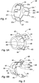
- the piston 270 ( figure 3 ) comprises longitudinal ribs formed in this example by branches 274 extending the plate 272 rearwardly. These branches 274 with semi-circular section or lunules are slidably accommodated in grooves 119 of corresponding section formed in the wall of the housing 113 of the stirrup 100 in positions homologous to those of the branches with the interposition of a device antimatter 300, 400 according to the FIGS. 4 or 5A, 5B .
- the branches 274 are preferably three in number distributed equiangularly around the axis xx of the housing 113. The piston 270 is thus locked in rotation in the housing 113 while remaining free in translation.
- the branches 274 overlap the rear portion 210 at the edge of the plate 222 and the flange 213 of the bearing 211.
- the disc forming the cage 231 holding the balls is also maintained by the branches 274 which is important for the realization of the sub- assembly constituted by the conversion cartridge 200 and greatly facilitates its implementation in the housing 113.
- control shaft 220 and its plate 222 are however free to rotate so that the rotational movement of the control shaft 220 results in a relative rotation of its plate 222 relative to the plate 272 integrated in the piston 270 which produces the translational movement of the piston 270, transmitted to the brake piston 5.
- the conversion piston 270 rests against the rear of the brake piston 5 by a not shown wear compensator, housed in the piston 270 forming the nut of a screw-nut connection.
- the compensation of the wear of the brake pads is in a manner known to those skilled in the art during the withdrawal movement of the nut, the release of the parking brake.
- the figure 4 shows an anti-misting device 300 intended to be interposed between the branches 274 of the piston 270 and the grooves 119 of the housing 113 of the stirrup 100.
- the anti-misting device 300 is a sheet metal part with a cylindrical ring 310 carrying lugs 320 each formed of two strips 321a, b provided with curved cylindrical tongues 322a, b having substantially the radius of the circular section of the ribs 274 of way to intervene, and if necessary to apply, on the ribs 274; the strips 321a, b then come on either side of each rib 274.
- the ring 310 partially caps the contour of the plate 272 between the ribs forming the ribs 274 and the edge 223 of the ring between the lamellae 321a, b comes against the front of the ribs 274.
- the tabs 320 are distributed equiangularly in number equal to that of the branches 274, that is to say the number of three.
- the antifatting device 300 is engaged on the plate 272 of the branches 274 of the piston 270 before the introduction of the spring 280 and the cage 290 as well as the clip 201. This anti-misting device 300 is not shown on the cartridge conversion of movement 200 of Figures 2A, 2B.
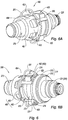
- the figure 5 in parts 5A, 5B; shows an alternative embodiment of the antimatter device 400 combined in this case with a cage.
- the device 400 consists of a ring 410 in the form of a split flange carrying tabs 420 distributed equiangularly and in number corresponding to that of the branch-shaped ribs 274 of the piston 270, that is to say the number of three with a distribution at 120 °.
- the tabs 420 each consist of two slats 421a, b carrying curved cylindrical tongues 422a, b having substantially a homothetic section of that of the branches 274 of the piston 270.
- the lamellae 421, b end with retaining nozzles 423a, b so as to come behind the ends of the branches 274 and to hang behind them while maintaining the elasticity of the tabs 420.
- the tabs 420 are carried by the slotted ring-shaped ring 410 provided with projecting portions 495 in the radial direction, comparable to the flange 293 and its protruding portions 295 of the cage 290 of the embodiment of the figure 2 .
- the slotted flange 410 is connected by blades 492 to a ring with a return forming a bottom 491.
- the bottom 491 also carries intermediate blades 494 coming elastically projecting.
- the assembly of the blades 492 and intermediate blades 494 with the bottom 491 and the ring-shaped split flange 410 generally have a frustoconical shape.
- the assembly has a ternary structure, with three tabs 420, three blades 492 and three intermediate blades 494.
- the intermediate blades 494 have the same function as the intermediate blades 294 of the cage 290.
- the elements 491 , 492, 494, 495 with the slotted flange 410 and its projecting parts, constitute a cage 490.
- FIGS. 6A, 6B show the mounting of the mopping device 400 on the conversion cartridge 200 with the clip 201.
- Figure 6B shows in particular the attachment of the retaining nozzles 423a, b behind the branches 274 of the piston 270, branches further surrounded by the cylindrical tongues 422a, b and the lamellae 421a, b supported on the periphery of the plate 272 of the piston.
- Other parts of the cartridge also referenced will not be described again.
- the cartridge 200 is composed of a small number of parts and constitutes an assembled unit, ready to be installed in the barrel of the brake caliper 100. This installation does not hinder or complicate the subsequent installation of the brake piston. and does not disturb the purge of the brake circuit.
- the present invention relates to the field of motor vehicle disc brake systems.
Landscapes
- Engineering & Computer Science (AREA)
- General Engineering & Computer Science (AREA)
- Mechanical Engineering (AREA)
- Transportation (AREA)
- Braking Arrangements (AREA)
Description
- La présente invention concerne un frein à disque comprenant un étrier flottant chevauchant le disque de frein portant un patin fixe et formant un cylindre logeant un piston portant un patin mobile pour serrer le disque de frein,
- le piston étant commandé par le circuit hydraulique et par le système de freins de stationnement par l'intermédiaire d'une cartouche de conversion de mouvement transformant le mouvement de pivotement du levier du frein, porté par l'étrier en un mouvement de translation pour pousser le piston de frein,
- le cylindre ayant une partie avant logeant le piston de frein et une partie arrière formant un logement recevant la cartouche de conversion à forme de révolution venant contre le patin mobile et le fond du cylindre,
- la cartouche retenue dans le logement par un clip traversant de manière étanche un orifice axial du fond du cylindre pour relier son arbre de commande au levier du frein de stationnement.
- On connaît déjà un tel frein à disque décrit dans le document
EP 1 936 227 . Ce document concerne notamment un procédé d'assemblage d'un frein à disque et en particulier l'assemblage de la cartouche convertissant le mouvement de rotation du levier du frein en un mouvement de translation du piston de frein pour mettre en oeuvre le frein de stationnement ou le libérer. - Dans ce montage la partie arrière de la cartouche comporte un pion venant dans un trou du fond du logement recevant la cartouche dans le cylindre de l'étrier de frein. Cette réalisation est relativement compliquée à fabriquer et à installer ; de plus le pion subit des efforts de rotation importants lors de l'actionnement du frein à main.
- La présente invention a pour but de simplifier la fabrication de l'étrier de frein en réduisant le nombre de pièces constituant la cartouche de conversion de mouvement et la fabrication de l'étrier et en évitant les risques de matage.
- A cet effet l'invention concerne un frein à disque du type défini ci-dessus, caractérisé en ce que,
- A) la cartouche de conversion comprend:
- une partie arrière appuyée contre le fond du logement du cylindre et se composant :
- * d'un palier en forme de manchon muni d'une collerette appuyée autour d'un orifice de passage du fond du logement traversé partiellement par le manchon, et
- * d'un arbre de commande relié au levier pivotant et portant un premier plateau,
- une partie avant appuyée contre le piston de frein, mobile en translation par rapport au cylindre mais bloquée en rotation, et se composant:
- * d'un piston muni d'un deuxième plateau destiné à coopérer avec le premier plateau de l'arbre de commande avec interposition de billes mobiles dans des rampes dans les deux plateaux pour transformer le mouvement de rotation relatif entre les deux plateaux en un mouvement de translation du piston, et
- * d'une cage de retenue du piston de conversion dans le cylindre par l'intermédiaire d'un clip, un ressort de rappel étant interposé entre la cage et le piston pour agir contre le mouvement de translation généré par les plateaux et les billes,
- une partie arrière appuyée contre le fond du logement du cylindre et se composant :
- B) le cylindre comporte, au niveau de sa partie arrière formant le logement recevant la cartouche de conversion, au moins une rainure longitudinale et le piston de conversion comporte à sa périphérie, une nervure longitudinale de section complémentaire à celle de la rainure longitudinale, pour coopérer avec celle-ci et bloquer la rotation de la partie avant de la cartouche en la laissant libre en translation.
- C) un dispositif antimatage interposé entre les branches du piston et les rainures du logement de l'étrier, comprend un anneau portant des pattes réparties suivant la répartition des branches du piston et ayant des languettes cylindriques, cintrées sensiblement suivant la forme de la section des branches pour couvrir celles-ci.
- Ainsi, le blocage en rotation du piston de la cartouche, c'est-à-dire de l'écrou mobile de la cartouche est réalisé directement sur l'étrier ; le blocage en rotation se fait par la ou les nervures longitudinales portées par la partie avant de la cartouche et la ou les rainures longitudinales homologues réalisées dans le logement de la cartouche dans l'étrier avec interposition du dispositif antimatage .
- On supprime ainsi de manière très avantageuse le boîtier arrière de la cartouche et son pion antirotation logé dans un trou au fond de l'étrier. Le boîtier de la partie arrière de l'état de la technique est remplacé selon l'invention par un simple palier arrière à section en forme de L. La suppression du boîtier de la partie arrière améliore la purgeabilité du circuit de frein puisqu'il n'y a aucune pièce fermée dans la cartouche de conversion selon l'invention. Cela simplifie la réalisation de la cage et raccourcit la longueur du cylindre ou fût de l'étrier recevant la cartouche.
- L'invention simplifie également l'assemblage de la cartouche qui se fait directement en bord de chaîne d'assemblage du frein et supprimant une machine dédiée à la préparation de la cartouche assemblée. Il n'y a plus de clipage de la cage sur le boîtier arrière ce qui évite le risque de formation de copeaux.
- Enfin, cette forme de réalisation peut s'appliquer à des pistons de plus petit diamètre que celui des pistons utilisés actuellement avec des efforts identiques exercés par les pistons.
- Suivant une autre caractéristique avantageuse, le logement de la cartouche dans l'étrier comporte trois rainures longitudinales et le piston est muni de trois nervures longitudinales, les rainures étant réparties de manière équiangulaire et les nervures étant dans des positions homologues à celles des rainures.
- Ces trois rainures longitudinales et les trois nervures longitudinales du piston de la cartouche, permettent un excellent blocage en rotation du piston de la cartouche tout en évitant les problèmes liés au couple important qui peut être appliqué au piston de conversion par la liaison constituée par la transmission à billes entre les plateaux. Cet excellent blocage en rotation est également favorable au rappel du piston de conversion lorsque le frein de stationnement est libéré.
- Suivant une autre caractéristique avantageuse au moins une rainure du logement a une section en arc de cercle et notamment en demi-cercle et la nervure portée par le piston de la cartouche a une section en forme d'arc de cercle homologue, c'est-à-dire homothétique de celle de la rainure, tenant compte de l'épaisseur du dispositif antimatage. Cette forme de rainure et de nervure est très facile à réaliser.
- Suivant une autre caractéristique avantageuse, la nervure longitudinale est constituée par une branche dépassant le plateau vers l'arrière et chevauchant au moins une fraction de longueur axiale de la partie arrière de la cartouche de conversion.
- La longueur de la nervure longitudinale constituée ainsi par une branche et surtout la longueur des nervures longitudinales, de préférence au nombre de trois, du piston de conversion, permettent un excellent guidage et tenue du piston dans l'étrier sans risque de matage. Les branches dépassant vers l'arrière permettent de réduire la longueur axiale de la cartouche de conversion sans que cela ne soit au détriment du guidage d'autant plus que les branches sont à la fois maintenues par le palier arrière et le plateau de l'arbre de commande de la cartouche, dans l'espace libre entouré par les branches. Dans ces conditions, même sous un effort qui pourrait être violent, les branches ne peuvent sortir de leurs rainures puisqu'elles y sont maintenues, en quelque sorte bloquées, par la présence du dispositif antimatage de la partie arrière de la cartouche.
- Suivant une autre caractéristique avantageuse, le logement de la cartouche comporte un épaulement recevant en appui la collerette de la cage et une gorge périphérique pour recevoir le clip.
- Suivant une autre caractéristique avantageuse, la cage est une pièce en acier élastique de forme globale tronconique ayant un fond en forme de couronne portant des lames reliées à une collerette et des lames intermédiaires, d'extrémité libre, recevant le clip.
- Cette cage et la coopération de la cage d'une part avec l'épaulement et d'autre part avec la gorge périphérique recevant le clip, garantissent un excellent accrochage solidaire de la cartouche de conversion dans son logement. Cet accrochage est solidaire et ne peut s'ouvrir de lui-même. Il nécessite un outil particulier tel qu'un manchon, prenant appui sur la forme tronconique de la cage pour resserrer progressivement les lamelles de la cage, escamoter la collerette et la dégager de sa gorge. La mise en place se fait dans les mêmes conditions, en procédant dans l'ordre inverse.
- Globalement, le frein à disque équipé d'une telle cartouche de conversion de mouvement avec un dispositif antimatage est simple à réaliser et à assembler grâce au nombre réduit de pièces. Il permet un excellent fonctionnement du frein et en garantit la fiabilité.
- La présente invention sera décrite ci-après de manière plus détaillée à l'aide des dessins annexés dans lesquels:
- la
figure 1 est une vue en coupe schématique d'un étrier de frein placé sur le disque de frein, montrant le piston de frein sans la cartouche de conversion, - la
figure 2 montre en vue de côté légèrement en perspective la cartouche de conversion sans le dispositif antimatage, - la
figure 3 est une vue en perspective du piston de la cartouche de conversion, - la
figure 4 est une vue en perspective d'un premier mode de réalisation du dispositif antimatage de la cartouche de conversion, - la
figure 5 montre dans ses parties 5A, 5B, deux vues en perspective suivant des directions différentes d'un second mode de réalisation d'un dispositif antimatage intégré à la cage de la cartouche, - les
figures 6A, 6B sont des vues en perspective suivant des directions différentes de la cartouche de conversion équipée du dispositif antimatage selon lesfigures 5A, 5B . - Par convention, pour simplifier la description du frein à disque selon l'invention, on utilisera l'orientation donnée par l'axe xx de la
figure 1 dont le côté gauche est dirigé vers ce qui est considéré comme l'avant et le côté droit, dirigé vers ce qui est considéré comme l'arrière: ainsi l'avant du piston de frein est tourné vers son patin de frein et l'arrière du piston de frein, tourné vers son logement dans l'étrier. De même, la cartouche de conversion aura une partie avant du côté du piston de frein et une partie arrière du côté du fond de son logement dans l'étrier. - Selon la
figure 1 , l'invention concerne un frein à disque 1 associé au circuit de freinage et à la commande du frein de stationnement. L'étrier flottant 100 chevauche le disque de frein 2 et porte un patin fixe 3 et un patin mobile 4. Ce dernier est actionné par un piston de frein 5 logé dans le cylindre 110 (ou fût) de l'étrier 100. Le cylindre 110 délimite une chambre étanche 111 reliée au circuit de frein par un branchement 112 non détaillé. Cette chambre étanche 111 loge une cartouche de conversion de mouvement 200 (figure 2 ) appliquée contre le fond 114 du logement 113 du cylindre de l'étrier. Le logement 113 prolonge le cylindre 110 du piston de frein. Le fond 114 est muni d'un orifice 115 que traverse de manière étanche l'extrémité de la cartouche 200 (figure 2 ) pour la liaison d'entraînement avec le levier pivotant 120 relié à la commande du frein à main, dont le mouvement de rotation (pivotement) sera transformé en un mouvement de translation appliqué au piston de frein 5. - La cartouche de conversion de mouvement 200 représentée à la
figure 2 se compose d'une partie arrière 210 et d'une partie avant 260. Elle est représentée sans le dispositif antimatage 300 (figure 4 ) et 400 - La partie arrière 210 est formée d'un palier 211 comprenant un manchon 212 muni d'une collerette 213. Le manchon 212 se place dans l'orifice 115 du fond 114 de l'étrier 100 et sa collerette 213 s'appuie sur la surface du fond 114 entourant l'orifice 115. Le palier 211 muni d'un joint torique 214 pour assurer l'étanchéité par rapport à l'orifice 115, reçoit un arbre de commande 220 constitué par une partie cylindrique 221 terminée à l'avant par un premier plateau 222. La partie cylindrique 221 traverse le manchon 212 du palier 211 pour venir en saillie à l'arrière de l'étrier et recevoir le levier d'actionnement 120 du frein de stationnement. Le plateau 222 s'appuie contre la collerette 213 du palier 211. La face avant du plateau 222 est munie de gorges de profondeur variable pour coopérer avec des billes portées par une cage 231 et qui coopèrent dans les mêmes conditions avec le piston de conversion 270 bloqué en rotation mais mobile en translation.
- La partie avant 260 de la cartouche 200 se compose du piston de conversion 270 constitué par un manchon 271 portant à l'arrière un plateau 272 (second plateau) dont la face est munie de rainures de profondeur variable, complémentaires dans leur disposition et leur forme à celles des rainures du premier plateau 222 de l'arbre de commande 220. Les billes roulent dans les rainures homologues du plateau 222 de l'arbre de commande 220 et de celui 272 du piston 270 pour transformer le mouvement de rotation du plateau 222 de l'arbre de commande 220 en un mouvement de translation du piston de conversion 270 par le jeu des rampes complémentaires formées par les rainures comme cela est connu en soi. La partie avant 260 comprend également un ressort de compression 280 emmanché sur le manchon cylindrique 271 du piston de conversion et s'appuyant d'une part contre le plateau 272 du piston 270 et d'autre part contre le fond 291 d'une cage 290 également installée sur le manchon 271 du piston 270.
- La cage 290 est une pièce en acier élastique de forme globale tronconique comprenant une couronne constituant le fond 291 côté avant, portant des lames 292 reliées à une collerette fendue 293 tournée vers l'extérieur avec des parties en saillie 294 et des lames intermédiaires 295, libres. Un clip 201 est installé dans la cage 290 autour et entre les lames 292, 294, pour retenir la cartouche 200 dans son logement 113 de l'étrier 100. Pour la mise en place d'une manière connue en soi, la collerette fendue 293 et le clip 201 sont comprimés à l'aide d'un outil en forme de manchon. Le clip 201 retient la cage 290 en coopérant avec une gorge périphérique 118 du cylindre 110 et la collerette fendue 293 prend place dans le logement 113 contre un épaulement 117 dans l'étrier 100 comme cela est réalisé par le procédé de montage décrit au document
EP 1 936 227 cité ici à titre de référence. La cartouche 200 est ainsi bloquée dans son logement 113 dans une direction par son appui par l'intermédiaire de la collerette fendue 293 contre l'épaulement 117 et dans la direction opposée par le clip 201 accroché dans la gorge périphérique 118, seuls restant libres en mouvement, la tige de commande 220 et le piston 270. - Le piston 270 (
figure 3 ) comporte des nervures longitudinales constituées dans cet exemple, par des branches 274 prolongeant le plateau 272 vers l'arrière. Ces branches 274 à section de forme semi-circulaire ou de lunules sont logées en coulissement dans des rainures 119 de section correspondante réalisées dans la paroi du logement 113 de l'étrier 100 dans des positions homologues à celles des branches avec interposition d'un dispositif antimatage 300, 400 selon lesfigures 4 ou 5A, 5B . Les branches 274 sont de préférence au nombre de trois réparties de manière équiangulaire autour de l'axe xx du logement 113. Le piston 270 est ainsi bloqué en rotation dans le logement 113 tout en restant libre en translation. Les branches 274 chevauchent la partie arrière 210 au niveau du bord du plateau 222 et de la collerette 213 du palier 211. Le disque formant la cage 231 tenant les billes est également maintenu par les branches 274 ce qui est important pour la réalisation du sous-ensemble constitué par la cartouche de conversion 200 et facilite considérablement sa mise en place dans le logement 113. - Après installation de la cartouche 200, l'arbre de commande 220 et son plateau 222 sont en revanche libres en rotation de sorte que le mouvement de rotation de l'arbre de commande 220 se traduit par une rotation relative de son plateau 222 par rapport au plateau 272 intégré au piston 270 ce qui produit le mouvement de translation du piston 270, transmis au piston de frein 5.
- Le piston de conversion 270 s'appuie contre l'arrière du piston de frein 5 par un compensateur d'usure non représenté, logé dans le piston 270 formant l'écrou d'une liaison vis-écrou. La compensation de l'usure des patins de frein se fait de manière connue de l'homme du métier lors du mouvement de retrait de l'écrou, à la libération du frein de stationnement.
- La
figure 4 montre un dispositif antimatage 300 destiné à être interposé entre les branches 274 du piston 270 et les rainures 119 du logement 113 de l'étrier 100. - Le dispositif antimatage 300 est une pièce en tôle avec un anneau cylindrique 310 portant des pattes 320 formée chacune de deux lamelles 321a, b munies de languettes cylindriques cintrées 322a, b ayant sensiblement le rayon de la section circulaire des nervures en forme de branches 274 de façon à s'interposer, et le cas échéant à s'appliquer, sur les nervures 274; les lamelles 321a, b viennent alors de part et d'autre de chaque nervure 274.
- L'anneau 310 coiffe partiellement le contour du plateau 272 entre les nervures formant les nervures 274 et le bord 223 de l'anneau entre les lamelles 321a, b vient contre l'avant des nervures 274.
- Dans ce dispositif 300, les pattes 320 sont réparties de manière équiangulaire en nombre égal à celui des branches 274, c'est-à-dire au nombre de trois.
- Le dispositif antimatage 300 est engagé sur le plateau 272 des branches 274 du piston 270 avant la mise en place du ressort 280 et de la cage 290 ainsi que du clip 201. Ce dispositif antimatage 300 n'est pas représenté sur la cartouche de conversion de mouvement 200 des
figures 2A, 2B. - La
figure 5 dans ses parties 5A, 5B ; montre une variante de réalisation du dispositif antimatage 400 combiné dans ce cas à une cage. Le dispositif 400 se compose d'un anneau 410 en forme de collerette fendue portant des pattes 420 réparties de manière équiangulaire et en nombre correspondant à celui des nervures en forme de branches 274 du piston 270, c'est-à-dire au nombre de trois avec une répartition à 120°. Les pattes 420 se composent chacune de deux lamelles 421a, b portant des languettes cylindriques 422a, b cintrées ayant sensiblement une section homothétique de celle des branches 274 du piston 270. - Les lamelles 421, b se terminent par des becs de retenue 423a, b de manière à venir derrière l'extrémité des branches 274 et à s'accrocher derrière celles-ci tout en conservant l'élasticité des pattes 420.
- Les pattes 420 sont portées par l'anneau en forme de collerette fendue 410 munie de parties en saillie 495 dans la direction radiale, assimilable à la collerette 293 et à ses parties en saillie 295 de la cage 290 du mode de réalisation de la
figure 2 . La collerette fendue 410 est reliée par des lames 492 à un anneau avec un retour formant un fond 491. Le fond 491 porte également des lames intermédiaires 494 venant élastiquement en saillie. L'ensemble des lames 492 et des lames intermédiaires 494 avec le fond 491 et l'anneau en forme de collerette fendue 410, présentent globalement une forme tronconique. - Selon le mode de réalisation représenté, l'ensemble a une structure ternaire, avec trois pattes 420, trois lames 492 et trois lames intermédiaires 494. Les lames intermédiaires 494 ont la même fonction que les lames intermédiaires 294 de la cage 290. Les éléments 491, 492, 494, 495 avec la collerette fendue 410 et ses parties en saillie, constituent une cage 490.
- Les
figures 6A, 6B montrent le montage du dispositif antimatage 400 sur la cartouche de conversion 200 avec le clip 201. Lafigure 6B montre notamment l'accrochage des becs de retenue 423a, b derrière les branches 274 du piston 270, branches par ailleurs entourées par les languettes cylindriques 422a, b et les lamelles 421a, b s'appuyant sur la périphérie du plateau 272 du piston. Les autres parties de la cartouche également référencées ne seront pas décrites une nouvelle fois. - La cartouche 200 est composée d'un nombre réduit de pièces et constitue une unité assemblée, prête à être installée dans le fût de l'étrier de frein 100. Cette mise en place ne gêne ni ne complique l'installation ultérieure du piston de frein et ne perturbe pas ensuite la purge du circuit de frein.
- La présente invention concerne le domaine des systèmes de freins à disque de véhicules automobiles.
-
- 1
- Frein à disque
- 5
- Piston de frein
- 100
- Etrier
- 110
- Cylindre
- 111
- Chambre de piston
- 113
- Logement
- 114
- Fond du logement
- 115
- Orifice du fond du logement
- 117
- Epaulement
- 118
- Gorge périphérique
- 119
- Rainure
- 120
- Levier
- 200
- Cartouche de conversion de mouvement
- 201
- Clip
- 210
- Partie arrière de la cartouche
- 211
- Palier à section en forme de T
- 212
- Manchon
- 213
- Collerette
- 214
- Joint torique
- 220
- Arbre de commande
- 221
- Partie cylindrique
- 222
- Premier plateau
- 231
- Cage recevant les billes
- 260
- Partie avant de la cartouche
- 261
- Piston de conversion
- 262
- Manchon
- 263
- Deuxième plateau
- 274
- Nervure/branche longitudinale
- 275
- Ecrou
- 280
- Ressort de compression
- 290
- Cage
- 291
- Fond
- 292
- Lame
- 293
- Collerette fendue
- 294
- Lame intermédiaire
- 295
- Partie en saillie
- 300
- Dispositif antimatage
- 310
- Anneau
- 320
- Pattes
- 321a,b
- Lamelles
- 322a,b
- Languettes cylindriques cintrées
- 323
- Bord de l'anneau
- 400
- Dispositif antimatage
- 410
- Anneau en forme de collerette fendue
- 420
- Pattes
- 421a,b
- Lamelles
- 422a,b
- Languettes cylindriques
- 423a,b
- Becs de retenue
- 490
- Cage
- 491
- Fond
- 492
- Lame
- 493
- Collerette fendue
- 494
- Lame intermédiaire
- 495
- Partie en saillie
Claims (8)
- Frein à disque comprenant un étrier flottant (100) chevauchant le disque de frein (2) portant un patin fixe (3) et formant un cylindre (110) logeant un piston (5) portant un patin mobile (4) pour serrer le disque de frein,• le piston (5) étant commandé par le circuit hydraulique et par le système de frein de stationnement par l'intermédiaire d'une cartouche de conversion de mouvement (200) transformant le mouvement de pivotement du levier du frein de stationnement, porté par l'étrier (100) en un mouvement de translation pour pousser le piston de frein (5),• le cylindre (110) ayant une partie avant logeant le piston de frein (5) et une partie arrière formant un logement (113) recevant la cartouche de conversion (200) à forme de révolution venant contre le patin mobile et le fond du cylindre,• la cartouche (200) retenue dans le logement (113) par un clip (201), traversant de manière étanche un orifice axial du fond (114) du cylindre pour relier son arbre de commande au levier (120) du frein de stationnement,frein caractérisé en ce queA) la cartouche de conversion (200) comprend:- une partie arrière (210) appuyée contre le fond (114) du logement (113) du cylindre (110) et se composant :* d'un palier (211) en forme de manchon (212) muni d'une collerette (213) appuyée autour d'un orifice de passage (115) du fond du logement (113) traversé partiellement par le manchon (212), et* d'un arbre de commande (220) relié au levier pivotant (120) et portant un premier plateau (222),- une partie avant (260) appuyée contre le piston de frein (5), mobile en translation par rapport au cylindre (110) mais bloquée en rotation, et se composant :* d'un piston (270) muni d'un deuxième plateau (272) destiné à coopérer avec le premier plateau (222) de l'arbre de commande (220) avec interposition de billes mobiles dans des rampes dans les deux plateaux (222, 272) pour transformer le mouvement de rotation relatif des deux plateaux (222, 272) en un mouvement de translation du piston (270), et* d'une cage de retenue (290) du piston de conversion (200) dans le cylindre (110) par l'intermédiaire d'un clip (201),* un ressort de rappel (280) étant interposé entre la cage (290) et le piston (270) pour agir contre le mouvement de translation généré par les plateaux (222, 272) et les billes,B) le cylindre (110) comporte, au niveau de sa partie arrière formant le logement (113) recevant la cartouche de conversion (200), au moins une rainure longitudinale (119) et le piston de conversion (270) comporte à sa périphérie au moins une nervure longitudinale (274) de section complémentaire à celle de la rainure longitudinale (119), pour coopérer avec celle-ci et bloquer la rotation de la partie avant (260) de la cartouche (200) en laissant le piston (270) libre en translation,C) un dispositif antimatage (300, 400) interposé entre les nervures (274) du piston (270) et les rainures (119) du logement (113) de l'étrier (100), comprend un anneau (310, 410) portant des pattes (320, 420) réparties suivant la répartition des nervures (274) du piston et ayant des languettes cylindriques (322a, b; 422a, b), cintrées sensiblement suivant la forme de la section des branches (274) pour couvrir celles-ci dans les rainures longitudinales (119) du logement (113) du cylindre (110).
- Frein à disque selon la revendication 1,
caractérisé en ce que
le logement (113) de la cartouche (200) dans l'étrier (100) comporte trois rainures longitudinales (119) et le piston (270) est muni de trois nervures longitudinales (274), les rainures (119) étant réparties de manière équiangulaire et les nervures (274) étant dans des positions homologues à celles des rainures (119). - Frein à disque selon la revendication 1,
caractérisé en ce qu'
la rainure (119) du logement (113) a une section en arc de cercle et notamment en demi-cercle et la nervure (274) portée par le piston (270) de la cartouche (200) a une section en forme d'arc de cercle homothétique à celle de la rainure (119), tenant compte de l'épaisseur du dispositif antimatage (300, 400). - Frein à disque selon la revendication 1,
caractérisé en ce que
la nervure longitudinale (274) est constituée par une branche dépassant le plateau (272) vers l'arrière et chevauchant au moins une fraction de longueur axiale de la partie arrière (210). - Frein à disque selon la revendication 1,
caractérisé en ce que
le logement (113) de la cartouche (200) comporte un épaulement (117) pour recevoir en appui la collerette (293) de la cage (290) et une gorge périphérique (118) pour recevoir le clip (201). - Frein à disque selon la revendication 1,
caractérisé en ce que
la cage (290) est une pièce en acier élastique de forme globale tronconique ayant un fond (291) en forme de couronne portant des lames (292) reliées à une collerette fendue (293) et des lames intermédiaires (294), à l'extrémité libre, recevant le clip (201). - Frein à disque selon la revendication 1,
caractérisé en ce que
le dispositif antimatage (400) comporte des pattes (420) solidaires d'un anneau en forme de collerette fendue (410) muni de parties en saillie (491) et reliée par des lames (492) à un anneau avec un retour formant un fond (491) portant lui-même des pattes intermédiaires (494) en saillie élastiquement, et l'ensemble constituant une cage (490) portant les pattes (420). - Frein à disque selon la revendication 7,
caractérisé en ce que
les pattes (420) comportent des lamelles (421a, b) terminées par des becs de retenue (423a, b) au-delà des languettes cylindriques cintrées (422a, b) pour s'accrocher derrière l'extrémité des nervures (274) du piston (270).
Applications Claiming Priority (2)
| Application Number | Priority Date | Filing Date | Title |
|---|---|---|---|
| FR1005149A FR2969728B1 (fr) | 2010-12-27 | 2010-12-27 | Frein a disque a cartouche de conversion munie d'un dispositif antimatage |
| PCT/EP2011/071509 WO2012089440A1 (fr) | 2010-12-27 | 2011-12-01 | Frein a disque a cartouche de conversion munie d'un dispositif antimatage. |
Publications (2)
| Publication Number | Publication Date |
|---|---|
| EP2659156A1 EP2659156A1 (fr) | 2013-11-06 |
| EP2659156B1 true EP2659156B1 (fr) | 2016-04-06 |
Family
ID=44483978
Family Applications (1)
| Application Number | Title | Priority Date | Filing Date |
|---|---|---|---|
| EP11788865.1A Active EP2659156B1 (fr) | 2010-12-27 | 2011-12-01 | Frein a disque a cartouche de conversion munie d'un dispositif antimatage. |
Country Status (10)
| Country | Link |
|---|---|
| US (1) | US9187071B2 (fr) |
| EP (1) | EP2659156B1 (fr) |
| JP (1) | JP5863825B2 (fr) |
| KR (1) | KR101863678B1 (fr) |
| CN (1) | CN103562583B (fr) |
| ES (1) | ES2573795T3 (fr) |
| FR (1) | FR2969728B1 (fr) |
| PL (1) | PL2659156T3 (fr) |
| RU (1) | RU2538493C1 (fr) |
| WO (1) | WO2012089440A1 (fr) |
Families Citing this family (19)
| Publication number | Priority date | Publication date | Assignee | Title |
|---|---|---|---|---|
| WO2012167495A1 (fr) * | 2011-06-09 | 2012-12-13 | Beijingwest Industries Co., Ltd. | Étrier de frein à patin pivotant |
| CN104373489B (zh) * | 2014-11-27 | 2017-04-12 | 京西重工(上海)有限公司 | 一种盘式制动器 |
| WO2016162927A1 (fr) * | 2015-04-06 | 2016-10-13 | ユニサンティス エレクトロニクス シンガポール プライベート リミテッド | Dispositif de mémoire à semi-conducteurs en colonnes et son procédé de fabrication |
| US11399995B2 (en) | 2016-02-23 | 2022-08-02 | Deka Products Limited Partnership | Mobility device |
| WO2017147347A1 (fr) | 2016-02-23 | 2017-08-31 | Deka Products Limited Partnership | Système de commande de dispositif de mobilité |
| US10908045B2 (en) | 2016-02-23 | 2021-02-02 | Deka Products Limited Partnership | Mobility device |
| US10926756B2 (en) | 2016-02-23 | 2021-02-23 | Deka Products Limited Partnership | Mobility device |
| USD807260S1 (en) * | 2016-04-11 | 2018-01-09 | Christopher Mark Young | Brake conversion hub |
| CA3287428A1 (en) | 2016-04-14 | 2025-10-31 | Deka Products Limited Partnership | User control device for a transporter |
| FR3050493B1 (fr) * | 2016-04-26 | 2018-05-25 | Foundation Brakes France Sas | Ecrou a faible prix de revient pour systeme de freinage de vehicule |
| USD783474S1 (en) * | 2016-04-28 | 2017-04-11 | Ausco Products, Inc. | Brake |
| USD1047785S1 (en) | 2017-05-20 | 2024-10-22 | Deka Products Limited Partnership | Toggle control device |
| USD833930S1 (en) * | 2017-07-15 | 2018-11-20 | Deka Products Limited Partnership | Brake insert |
| USD884568S1 (en) | 2017-07-15 | 2020-05-19 | Deka Products Limited Partnership | Brake insert |
| CN107740826A (zh) * | 2017-11-21 | 2018-02-27 | 重庆比速汽车有限公司 | 新型浮钳盘式制动器 |
| ES3061234T3 (en) | 2018-06-07 | 2026-03-31 | Deka Products Lp | System and method for distributed utility service execution |
| CN110005887B (zh) * | 2019-04-30 | 2024-03-12 | 鞍山市昱虎流体设备有限公司 | 可拆装式防冰冻低温流体旋转接头 |
| FR3132684B1 (fr) | 2022-02-14 | 2024-06-14 | Hitachi Astemo France | Systeme pour augmenter la pression d’intervention d’un frein |
| CN116201820B (zh) * | 2023-05-05 | 2023-07-07 | 新乡市海创传动设备有限公司 | 一种起重机用防松脱联轴器结构 |
Family Cites Families (11)
| Publication number | Priority date | Publication date | Assignee | Title |
|---|---|---|---|---|
| US4635761A (en) * | 1985-08-30 | 1987-01-13 | Allied Corporation | Disc brake parking cartridge retention device |
| RU2156386C1 (ru) * | 1999-04-12 | 2000-09-20 | Открытое акционерное общество "Завод им. В.А. Дегтярева" | Дисковый тормоз с устройством для автоматической регулировки зазоров |
| FR2800825B1 (fr) * | 1999-11-08 | 2002-01-11 | Bosch Gmbh Robert | Rampe a billes et cylindre de freins comportant une telle rampe |
| FR2817218B1 (fr) * | 2000-11-28 | 2003-01-10 | Bosch Gmbh Robert | Cylindre de frein a disque avec mecanisme de frein de parc |
| US6659236B1 (en) * | 2002-06-28 | 2003-12-09 | Robert Bosch Corporation | Parking brake |
| FR2910574B1 (fr) * | 2006-12-20 | 2009-07-10 | Bosch Gmbh Robert | Procede d'assemblage d'un dispositif de freinage et dispositif de freinage assemble selon un tel procede. |
| CN101852257B (zh) * | 2009-03-30 | 2014-02-19 | 京西重工(上海)有限公司 | 带驻车制动的盘式制动钳 |
| JP5148668B2 (ja) * | 2010-01-26 | 2013-02-20 | 曙ブレーキ工業株式会社 | パーキング機構付ディスクブレーキ装置 |
| FR2963767B1 (fr) * | 2010-08-16 | 2012-08-03 | Bosch Gmbh Robert | Cartouche d'actionneur mecanique de frein de vehicule automobile |
| FR2966541B1 (fr) * | 2010-10-22 | 2012-11-30 | Bosch Gmbh Robert | Frein a disque muni d'une cartouche de conversion de mouvement |
| FR2966540B1 (fr) * | 2010-10-22 | 2012-11-30 | Bosch Gmbh Robert | Frein a disque a verrou de blocage de la cartouche de conversion par un verrou |
-
2010
- 2010-12-27 FR FR1005149A patent/FR2969728B1/fr not_active Expired - Fee Related
-
2011
- 2011-12-01 RU RU2013130295/11A patent/RU2538493C1/ru active
- 2011-12-01 PL PL11788865.1T patent/PL2659156T3/pl unknown
- 2011-12-01 US US13/976,574 patent/US9187071B2/en active Active
- 2011-12-01 CN CN201180062977.0A patent/CN103562583B/zh active Active
- 2011-12-01 EP EP11788865.1A patent/EP2659156B1/fr active Active
- 2011-12-01 JP JP2013545153A patent/JP5863825B2/ja active Active
- 2011-12-01 ES ES11788865.1T patent/ES2573795T3/es active Active
- 2011-12-01 KR KR1020137016645A patent/KR101863678B1/ko active Active
- 2011-12-01 WO PCT/EP2011/071509 patent/WO2012089440A1/fr not_active Ceased
Also Published As
| Publication number | Publication date |
|---|---|
| PL2659156T3 (pl) | 2016-10-31 |
| RU2538493C1 (ru) | 2015-01-10 |
| FR2969728A1 (fr) | 2012-06-29 |
| US20140262635A1 (en) | 2014-09-18 |
| KR20140012958A (ko) | 2014-02-04 |
| RU2013130295A (ru) | 2015-01-20 |
| US9187071B2 (en) | 2015-11-17 |
| CN103562583B (zh) | 2016-08-10 |
| ES2573795T3 (es) | 2016-06-10 |
| EP2659156A1 (fr) | 2013-11-06 |
| JP2014500464A (ja) | 2014-01-09 |
| WO2012089440A1 (fr) | 2012-07-05 |
| CN103562583A (zh) | 2014-02-05 |
| FR2969728B1 (fr) | 2013-01-18 |
| JP5863825B2 (ja) | 2016-02-17 |
| KR101863678B1 (ko) | 2018-06-01 |
Similar Documents
| Publication | Publication Date | Title |
|---|---|---|
| FR2969728A1 (fr) | Frein a disque a cartouche de conversion munie d'un dispositif antimatage | |
| EP2649341B1 (fr) | Frein à disque à verrou de blocage de la cartouche de conversion par un verrou | |
| EP2652352B1 (fr) | Frein à disque muni d'une cartouche de conversion de mouvement | |
| EP1225360B1 (fr) | Dispositif auto-centreur de butée de débrayage | |
| WO2012127146A1 (fr) | Dispositif d'obturation a verrouillage auto-activable | |
| FR2739159A1 (fr) | Moyens a rampes pour dispositif de rattrapage de jeu destine a equiper un embrayage a friction, notamment pour vehicule automobile | |
| EP0028955B1 (fr) | Frein à disque à étrier coulissant | |
| EP3175146B1 (fr) | Réducteur de couple | |
| FR2963767A1 (fr) | Cartouche d'actionneur mecanique de frein de vehicule automobile | |
| EP3449147A1 (fr) | Écrou à faible prix de revient pour système de freinage de véhicule | |
| FR2522755A1 (fr) | Mecanisme de debrayage pour dispositif d'embrayage | |
| EP0803031B1 (fr) | Frein a disque muni d'un dispositif d'actionnement mecanique | |
| FR2745616A1 (fr) | Dispositif de maintien, notamment pour vehicule automobile | |
| EP0186537B1 (fr) | Frein à disque | |
| EP0779446B1 (fr) | Ensemble élastique unitaire à pièces globalement annulaires et mécanisme d'embrayage comportant un tel ensemble élastique unitaire | |
| FR2791406A1 (fr) | Dispositif de montage d'un diaphragme sur un couvercle d'embrayage | |
| EP0395460B1 (fr) | Frein à disque à étrier coulissant | |
| FR2786837A1 (fr) | Recepteur hydraulique, notamment d'embrayage, a piston elastique | |
| WO2000000753A2 (fr) | Recepteur hydraulique, notamment d'embrayage, a tube guide solidaire d'un corps exterieur | |
| FR2760498A1 (fr) | Dispositif de debrayage et son procede de montage | |
| FR3086022A1 (fr) | Mecanisme d'embrayage a rattrapage d'usure | |
| FR3086021A1 (fr) | Mecanisme d'embrayage a rattrapage d'usure | |
| FR2556799A1 (fr) | Mecanisme d'embrayage, notamment pour vehicule automobile | |
| FR2533650A1 (fr) | Butee de debrayage, notamment pour vehicule automobile, et montage correspondant | |
| EP1439990B1 (fr) | Dispositif de commande de frein de stationnement |
Legal Events
| Date | Code | Title | Description |
|---|---|---|---|
| PUAI | Public reference made under article 153(3) epc to a published international application that has entered the european phase |
Free format text: ORIGINAL CODE: 0009012 |
|
| 17P | Request for examination filed |
Effective date: 20130729 |
|
| AK | Designated contracting states |
Kind code of ref document: A1 Designated state(s): AL AT BE BG CH CY CZ DE DK EE ES FI FR GB GR HR HU IE IS IT LI LT LU LV MC MK MT NL NO PL PT RO RS SE SI SK SM TR |
|
| DAX | Request for extension of the european patent (deleted) | ||
| GRAP | Despatch of communication of intention to grant a patent |
Free format text: ORIGINAL CODE: EPIDOSNIGR1 |
|
| INTG | Intention to grant announced |
Effective date: 20151102 |
|
| GRAS | Grant fee paid |
Free format text: ORIGINAL CODE: EPIDOSNIGR3 |
|
| GRAA | (expected) grant |
Free format text: ORIGINAL CODE: 0009210 |
|
| AK | Designated contracting states |
Kind code of ref document: B1 Designated state(s): AL AT BE BG CH CY CZ DE DK EE ES FI FR GB GR HR HU IE IS IT LI LT LU LV MC MK MT NL NO PL PT RO RS SE SI SK SM TR |
|
| REG | Reference to a national code |
Ref country code: GB Ref legal event code: FG4D Free format text: NOT ENGLISH |
|
| REG | Reference to a national code |
Ref country code: AT Ref legal event code: REF Ref document number: 788165 Country of ref document: AT Kind code of ref document: T Effective date: 20160415 Ref country code: CH Ref legal event code: EP |
|
| REG | Reference to a national code |
Ref country code: IE Ref legal event code: FG4D Free format text: LANGUAGE OF EP DOCUMENT: FRENCH |
|
| REG | Reference to a national code |
Ref country code: DE Ref legal event code: R096 Ref document number: 602011025024 Country of ref document: DE |
|
| REG | Reference to a national code |
Ref country code: ES Ref legal event code: FG2A Ref document number: 2573795 Country of ref document: ES Kind code of ref document: T3 Effective date: 20160610 |
|
| REG | Reference to a national code |
Ref country code: RO Ref legal event code: EPE |
|
| REG | Reference to a national code |
Ref country code: LT Ref legal event code: MG4D Ref country code: NL Ref legal event code: MP Effective date: 20160406 |
|
| REG | Reference to a national code |
Ref country code: AT Ref legal event code: MK05 Ref document number: 788165 Country of ref document: AT Kind code of ref document: T Effective date: 20160406 |
|
| PG25 | Lapsed in a contracting state [announced via postgrant information from national office to epo] |
Ref country code: NL Free format text: LAPSE BECAUSE OF FAILURE TO SUBMIT A TRANSLATION OF THE DESCRIPTION OR TO PAY THE FEE WITHIN THE PRESCRIBED TIME-LIMIT Effective date: 20160406 |
|
| PG25 | Lapsed in a contracting state [announced via postgrant information from national office to epo] |
Ref country code: FI Free format text: LAPSE BECAUSE OF FAILURE TO SUBMIT A TRANSLATION OF THE DESCRIPTION OR TO PAY THE FEE WITHIN THE PRESCRIBED TIME-LIMIT Effective date: 20160406 Ref country code: IS Free format text: LAPSE BECAUSE OF FAILURE TO SUBMIT A TRANSLATION OF THE DESCRIPTION OR TO PAY THE FEE WITHIN THE PRESCRIBED TIME-LIMIT Effective date: 20160806 Ref country code: LT Free format text: LAPSE BECAUSE OF FAILURE TO SUBMIT A TRANSLATION OF THE DESCRIPTION OR TO PAY THE FEE WITHIN THE PRESCRIBED TIME-LIMIT Effective date: 20160406 Ref country code: NO Free format text: LAPSE BECAUSE OF FAILURE TO SUBMIT A TRANSLATION OF THE DESCRIPTION OR TO PAY THE FEE WITHIN THE PRESCRIBED TIME-LIMIT Effective date: 20160706 |
|
| REG | Reference to a national code |
Ref country code: FR Ref legal event code: PLFP Year of fee payment: 6 |
|
| PG25 | Lapsed in a contracting state [announced via postgrant information from national office to epo] |
Ref country code: AT Free format text: LAPSE BECAUSE OF FAILURE TO SUBMIT A TRANSLATION OF THE DESCRIPTION OR TO PAY THE FEE WITHIN THE PRESCRIBED TIME-LIMIT Effective date: 20160406 Ref country code: RS Free format text: LAPSE BECAUSE OF FAILURE TO SUBMIT A TRANSLATION OF THE DESCRIPTION OR TO PAY THE FEE WITHIN THE PRESCRIBED TIME-LIMIT Effective date: 20160406 Ref country code: PT Free format text: LAPSE BECAUSE OF FAILURE TO SUBMIT A TRANSLATION OF THE DESCRIPTION OR TO PAY THE FEE WITHIN THE PRESCRIBED TIME-LIMIT Effective date: 20160808 Ref country code: LV Free format text: LAPSE BECAUSE OF FAILURE TO SUBMIT A TRANSLATION OF THE DESCRIPTION OR TO PAY THE FEE WITHIN THE PRESCRIBED TIME-LIMIT Effective date: 20160406 Ref country code: GR Free format text: LAPSE BECAUSE OF FAILURE TO SUBMIT A TRANSLATION OF THE DESCRIPTION OR TO PAY THE FEE WITHIN THE PRESCRIBED TIME-LIMIT Effective date: 20160707 Ref country code: HR Free format text: LAPSE BECAUSE OF FAILURE TO SUBMIT A TRANSLATION OF THE DESCRIPTION OR TO PAY THE FEE WITHIN THE PRESCRIBED TIME-LIMIT Effective date: 20160406 Ref country code: SE Free format text: LAPSE BECAUSE OF FAILURE TO SUBMIT A TRANSLATION OF THE DESCRIPTION OR TO PAY THE FEE WITHIN THE PRESCRIBED TIME-LIMIT Effective date: 20160406 |
|
| REG | Reference to a national code |
Ref country code: DE Ref legal event code: R097 Ref document number: 602011025024 Country of ref document: DE |
|
| PG25 | Lapsed in a contracting state [announced via postgrant information from national office to epo] |
Ref country code: SK Free format text: LAPSE BECAUSE OF FAILURE TO SUBMIT A TRANSLATION OF THE DESCRIPTION OR TO PAY THE FEE WITHIN THE PRESCRIBED TIME-LIMIT Effective date: 20160406 Ref country code: DK Free format text: LAPSE BECAUSE OF FAILURE TO SUBMIT A TRANSLATION OF THE DESCRIPTION OR TO PAY THE FEE WITHIN THE PRESCRIBED TIME-LIMIT Effective date: 20160406 Ref country code: EE Free format text: LAPSE BECAUSE OF FAILURE TO SUBMIT A TRANSLATION OF THE DESCRIPTION OR TO PAY THE FEE WITHIN THE PRESCRIBED TIME-LIMIT Effective date: 20160406 |
|
| PLBE | No opposition filed within time limit |
Free format text: ORIGINAL CODE: 0009261 |
|
| STAA | Information on the status of an ep patent application or granted ep patent |
Free format text: STATUS: NO OPPOSITION FILED WITHIN TIME LIMIT |
|
| PG25 | Lapsed in a contracting state [announced via postgrant information from national office to epo] |
Ref country code: SM Free format text: LAPSE BECAUSE OF FAILURE TO SUBMIT A TRANSLATION OF THE DESCRIPTION OR TO PAY THE FEE WITHIN THE PRESCRIBED TIME-LIMIT Effective date: 20160406 |
|
| 26N | No opposition filed |
Effective date: 20170110 |
|
| PG25 | Lapsed in a contracting state [announced via postgrant information from national office to epo] |
Ref country code: SI Free format text: LAPSE BECAUSE OF FAILURE TO SUBMIT A TRANSLATION OF THE DESCRIPTION OR TO PAY THE FEE WITHIN THE PRESCRIBED TIME-LIMIT Effective date: 20160406 Ref country code: BE Free format text: LAPSE BECAUSE OF NON-PAYMENT OF DUE FEES Effective date: 20161231 |
|
| REG | Reference to a national code |
Ref country code: CH Ref legal event code: PL |
|
| PG25 | Lapsed in a contracting state [announced via postgrant information from national office to epo] |
Ref country code: MC Free format text: LAPSE BECAUSE OF FAILURE TO SUBMIT A TRANSLATION OF THE DESCRIPTION OR TO PAY THE FEE WITHIN THE PRESCRIBED TIME-LIMIT Effective date: 20160406 |
|
| REG | Reference to a national code |
Ref country code: IE Ref legal event code: MM4A |
|
| PG25 | Lapsed in a contracting state [announced via postgrant information from national office to epo] |
Ref country code: LU Free format text: LAPSE BECAUSE OF NON-PAYMENT OF DUE FEES Effective date: 20161201 Ref country code: CH Free format text: LAPSE BECAUSE OF NON-PAYMENT OF DUE FEES Effective date: 20161231 Ref country code: LI Free format text: LAPSE BECAUSE OF NON-PAYMENT OF DUE FEES Effective date: 20161231 |
|
| REG | Reference to a national code |
Ref country code: FR Ref legal event code: PLFP Year of fee payment: 7 |
|
| PG25 | Lapsed in a contracting state [announced via postgrant information from national office to epo] |
Ref country code: IE Free format text: LAPSE BECAUSE OF NON-PAYMENT OF DUE FEES Effective date: 20161201 |
|
| REG | Reference to a national code |
Ref country code: BE Ref legal event code: MM Effective date: 20161231 |
|
| PG25 | Lapsed in a contracting state [announced via postgrant information from national office to epo] |
Ref country code: HU Free format text: LAPSE BECAUSE OF FAILURE TO SUBMIT A TRANSLATION OF THE DESCRIPTION OR TO PAY THE FEE WITHIN THE PRESCRIBED TIME-LIMIT; INVALID AB INITIO Effective date: 20111201 Ref country code: CY Free format text: LAPSE BECAUSE OF FAILURE TO SUBMIT A TRANSLATION OF THE DESCRIPTION OR TO PAY THE FEE WITHIN THE PRESCRIBED TIME-LIMIT Effective date: 20160406 |
|
| PG25 | Lapsed in a contracting state [announced via postgrant information from national office to epo] |
Ref country code: MK Free format text: LAPSE BECAUSE OF FAILURE TO SUBMIT A TRANSLATION OF THE DESCRIPTION OR TO PAY THE FEE WITHIN THE PRESCRIBED TIME-LIMIT Effective date: 20160406 |
|
| PG25 | Lapsed in a contracting state [announced via postgrant information from national office to epo] |
Ref country code: BG Free format text: LAPSE BECAUSE OF FAILURE TO SUBMIT A TRANSLATION OF THE DESCRIPTION OR TO PAY THE FEE WITHIN THE PRESCRIBED TIME-LIMIT Effective date: 20160406 |
|
| PG25 | Lapsed in a contracting state [announced via postgrant information from national office to epo] |
Ref country code: MT Free format text: LAPSE BECAUSE OF FAILURE TO SUBMIT A TRANSLATION OF THE DESCRIPTION OR TO PAY THE FEE WITHIN THE PRESCRIBED TIME-LIMIT Effective date: 20160406 |
|
| PG25 | Lapsed in a contracting state [announced via postgrant information from national office to epo] |
Ref country code: AL Free format text: LAPSE BECAUSE OF FAILURE TO SUBMIT A TRANSLATION OF THE DESCRIPTION OR TO PAY THE FEE WITHIN THE PRESCRIBED TIME-LIMIT Effective date: 20160406 |
|
| PGFP | Annual fee paid to national office [announced via postgrant information from national office to epo] |
Ref country code: DE Payment date: 20251126 Year of fee payment: 15 |
|
| PGFP | Annual fee paid to national office [announced via postgrant information from national office to epo] |
Ref country code: GB Payment date: 20251119 Year of fee payment: 15 |
|
| PGFP | Annual fee paid to national office [announced via postgrant information from national office to epo] |
Ref country code: IT Payment date: 20251119 Year of fee payment: 15 |
|
| PGFP | Annual fee paid to national office [announced via postgrant information from national office to epo] |
Ref country code: FR Payment date: 20251120 Year of fee payment: 15 |
|
| PGFP | Annual fee paid to national office [announced via postgrant information from national office to epo] |
Ref country code: TR Payment date: 20251124 Year of fee payment: 15 |
|
| PGFP | Annual fee paid to national office [announced via postgrant information from national office to epo] |
Ref country code: CZ Payment date: 20251204 Year of fee payment: 15 |
|
| PGFP | Annual fee paid to national office [announced via postgrant information from national office to epo] |
Ref country code: PL Payment date: 20251124 Year of fee payment: 15 |
|
| PGFP | Annual fee paid to national office [announced via postgrant information from national office to epo] |
Ref country code: RO Payment date: 20251202 Year of fee payment: 15 |
|
| PGFP | Annual fee paid to national office [announced via postgrant information from national office to epo] |
Ref country code: ES Payment date: 20260102 Year of fee payment: 15 |