EP2657005B1 - Abblasbaugruppe für eine Siegeleinheit einer Verpackungsvorrichtung - Google Patents
Abblasbaugruppe für eine Siegeleinheit einer Verpackungsvorrichtung Download PDFInfo
- Publication number
- EP2657005B1 EP2657005B1 EP12003000.2A EP12003000A EP2657005B1 EP 2657005 B1 EP2657005 B1 EP 2657005B1 EP 12003000 A EP12003000 A EP 12003000A EP 2657005 B1 EP2657005 B1 EP 2657005B1
- Authority
- EP
- European Patent Office
- Prior art keywords
- blowing
- housing
- blow
- compressed air
- assembly according
- Prior art date
- Legal status (The legal status is an assumption and is not a legal conclusion. Google has not performed a legal analysis and makes no representation as to the accuracy of the status listed.)
- Active
Links
Images


Classifications
-
- B—PERFORMING OPERATIONS; TRANSPORTING
- B08—CLEANING
- B08B—CLEANING IN GENERAL; PREVENTION OF FOULING IN GENERAL
- B08B5/00—Cleaning by methods involving the use of air flow or gas flow
- B08B5/02—Cleaning by the force of jets, e.g. blowing-out cavities
-
- B—PERFORMING OPERATIONS; TRANSPORTING
- B29—WORKING OF PLASTICS; WORKING OF SUBSTANCES IN A PLASTIC STATE IN GENERAL
- B29C—SHAPING OR JOINING OF PLASTICS; SHAPING OF MATERIAL IN A PLASTIC STATE, NOT OTHERWISE PROVIDED FOR; AFTER-TREATMENT OF THE SHAPED PRODUCTS, e.g. REPAIRING
- B29C65/00—Joining or sealing of preformed parts, e.g. welding of plastics materials; Apparatus therefor
- B29C65/74—Joining or sealing of preformed parts, e.g. welding of plastics materials; Apparatus therefor by welding and severing, or by joining and severing, the severing being performed in the area to be joined, next to the area to be joined, in the joint area or next to the joint area
- B29C65/745—Joining or sealing of preformed parts, e.g. welding of plastics materials; Apparatus therefor by welding and severing, or by joining and severing, the severing being performed in the area to be joined, next to the area to be joined, in the joint area or next to the joint area using a single unit having both a severing tool and a welding tool
-
- B—PERFORMING OPERATIONS; TRANSPORTING
- B29—WORKING OF PLASTICS; WORKING OF SUBSTANCES IN A PLASTIC STATE IN GENERAL
- B29C—SHAPING OR JOINING OF PLASTICS; SHAPING OF MATERIAL IN A PLASTIC STATE, NOT OTHERWISE PROVIDED FOR; AFTER-TREATMENT OF THE SHAPED PRODUCTS, e.g. REPAIRING
- B29C65/00—Joining or sealing of preformed parts, e.g. welding of plastics materials; Apparatus therefor
- B29C65/74—Joining or sealing of preformed parts, e.g. welding of plastics materials; Apparatus therefor by welding and severing, or by joining and severing, the severing being performed in the area to be joined, next to the area to be joined, in the joint area or next to the joint area
- B29C65/749—Removing scrap
-
- B—PERFORMING OPERATIONS; TRANSPORTING
- B29—WORKING OF PLASTICS; WORKING OF SUBSTANCES IN A PLASTIC STATE IN GENERAL
- B29C—SHAPING OR JOINING OF PLASTICS; SHAPING OF MATERIAL IN A PLASTIC STATE, NOT OTHERWISE PROVIDED FOR; AFTER-TREATMENT OF THE SHAPED PRODUCTS, e.g. REPAIRING
- B29C66/00—General aspects of processes or apparatus for joining preformed parts
- B29C66/004—Preventing sticking together, e.g. of some areas of the parts to be joined
- B29C66/0042—Preventing sticking together, e.g. of some areas of the parts to be joined of the joining tool and the parts to be joined
- B29C66/0044—Preventing sticking together, e.g. of some areas of the parts to be joined of the joining tool and the parts to be joined using a separating sheet, e.g. fixed on the joining tool
-
- B—PERFORMING OPERATIONS; TRANSPORTING
- B29—WORKING OF PLASTICS; WORKING OF SUBSTANCES IN A PLASTIC STATE IN GENERAL
- B29C—SHAPING OR JOINING OF PLASTICS; SHAPING OF MATERIAL IN A PLASTIC STATE, NOT OTHERWISE PROVIDED FOR; AFTER-TREATMENT OF THE SHAPED PRODUCTS, e.g. REPAIRING
- B29C66/00—General aspects of processes or apparatus for joining preformed parts
- B29C66/01—General aspects dealing with the joint area or with the area to be joined
- B29C66/05—Particular design of joint configurations
- B29C66/10—Particular design of joint configurations particular design of the joint cross-sections
- B29C66/11—Joint cross-sections comprising a single joint-segment, i.e. one of the parts to be joined comprising a single joint-segment in the joint cross-section
- B29C66/112—Single lapped joints
- B29C66/1122—Single lap to lap joints, i.e. overlap joints
-
- B—PERFORMING OPERATIONS; TRANSPORTING
- B29—WORKING OF PLASTICS; WORKING OF SUBSTANCES IN A PLASTIC STATE IN GENERAL
- B29C—SHAPING OR JOINING OF PLASTICS; SHAPING OF MATERIAL IN A PLASTIC STATE, NOT OTHERWISE PROVIDED FOR; AFTER-TREATMENT OF THE SHAPED PRODUCTS, e.g. REPAIRING
- B29C66/00—General aspects of processes or apparatus for joining preformed parts
- B29C66/40—General aspects of joining substantially flat articles, e.g. plates, sheets or web-like materials; Making flat seams in tubular or hollow articles; Joining single elements to substantially flat surfaces
- B29C66/41—Joining substantially flat articles ; Making flat seams in tubular or hollow articles
- B29C66/43—Joining a relatively small portion of the surface of said articles
- B29C66/431—Joining the articles to themselves
- B29C66/4312—Joining the articles to themselves for making flat seams in tubular or hollow articles, e.g. transversal seams
- B29C66/43121—Closing the ends of tubular or hollow single articles, e.g. closing the ends of bags
-
- B—PERFORMING OPERATIONS; TRANSPORTING
- B29—WORKING OF PLASTICS; WORKING OF SUBSTANCES IN A PLASTIC STATE IN GENERAL
- B29C—SHAPING OR JOINING OF PLASTICS; SHAPING OF MATERIAL IN A PLASTIC STATE, NOT OTHERWISE PROVIDED FOR; AFTER-TREATMENT OF THE SHAPED PRODUCTS, e.g. REPAIRING
- B29C66/00—General aspects of processes or apparatus for joining preformed parts
- B29C66/80—General aspects of machine operations or constructions and parts thereof
- B29C66/81—General aspects of the pressing elements, i.e. the elements applying pressure on the parts to be joined in the area to be joined, e.g. the welding jaws or clamps
- B29C66/812—General aspects of the pressing elements, i.e. the elements applying pressure on the parts to be joined in the area to be joined, e.g. the welding jaws or clamps characterised by the composition, by the structure, by the intensive physical properties or by the optical properties of the material constituting the pressing elements, e.g. constituting the welding jaws or clamps
- B29C66/8122—General aspects of the pressing elements, i.e. the elements applying pressure on the parts to be joined in the area to be joined, e.g. the welding jaws or clamps characterised by the composition, by the structure, by the intensive physical properties or by the optical properties of the material constituting the pressing elements, e.g. constituting the welding jaws or clamps characterised by the composition of the material constituting the pressing elements, e.g. constituting the welding jaws or clamps
-
- B—PERFORMING OPERATIONS; TRANSPORTING
- B29—WORKING OF PLASTICS; WORKING OF SUBSTANCES IN A PLASTIC STATE IN GENERAL
- B29C—SHAPING OR JOINING OF PLASTICS; SHAPING OF MATERIAL IN A PLASTIC STATE, NOT OTHERWISE PROVIDED FOR; AFTER-TREATMENT OF THE SHAPED PRODUCTS, e.g. REPAIRING
- B29C66/00—General aspects of processes or apparatus for joining preformed parts
- B29C66/80—General aspects of machine operations or constructions and parts thereof
- B29C66/83—General aspects of machine operations or constructions and parts thereof characterised by the movement of the joining or pressing tools
- B29C66/832—Reciprocating joining or pressing tools
- B29C66/8322—Joining or pressing tools reciprocating along one axis
-
- B—PERFORMING OPERATIONS; TRANSPORTING
- B29—WORKING OF PLASTICS; WORKING OF SUBSTANCES IN A PLASTIC STATE IN GENERAL
- B29C—SHAPING OR JOINING OF PLASTICS; SHAPING OF MATERIAL IN A PLASTIC STATE, NOT OTHERWISE PROVIDED FOR; AFTER-TREATMENT OF THE SHAPED PRODUCTS, e.g. REPAIRING
- B29C66/00—General aspects of processes or apparatus for joining preformed parts
- B29C66/80—General aspects of machine operations or constructions and parts thereof
- B29C66/84—Specific machine types or machines suitable for specific applications
- B29C66/849—Packaging machines
-
- B—PERFORMING OPERATIONS; TRANSPORTING
- B65—CONVEYING; PACKING; STORING; HANDLING THIN OR FILAMENTARY MATERIAL
- B65B—MACHINES, APPARATUS OR DEVICES FOR, OR METHODS OF, PACKAGING ARTICLES OR MATERIALS; UNPACKING
- B65B31/00—Packaging articles or materials under special atmospheric or gaseous conditions; Adding propellants to aerosol containers
- B65B31/02—Filling, closing, or filling and closing, containers or wrappers in chambers maintained under vacuum or superatmospheric pressure or containing a special atmosphere, e.g. of inert gas
- B65B31/024—Filling, closing, or filling and closing, containers or wrappers in chambers maintained under vacuum or superatmospheric pressure or containing a special atmosphere, e.g. of inert gas specially adapted for wrappers or bags
-
- B—PERFORMING OPERATIONS; TRANSPORTING
- B65—CONVEYING; PACKING; STORING; HANDLING THIN OR FILAMENTARY MATERIAL
- B65B—MACHINES, APPARATUS OR DEVICES FOR, OR METHODS OF, PACKAGING ARTICLES OR MATERIALS; UNPACKING
- B65B51/00—Devices for, or methods of, sealing or securing package folds or closures; Devices for gathering or twisting wrappers, or necks of bags
- B65B51/10—Applying or generating heat or pressure or combinations thereof
- B65B51/14—Applying or generating heat or pressure or combinations thereof by reciprocating or oscillating members
- B65B51/146—Closing bags
-
- B—PERFORMING OPERATIONS; TRANSPORTING
- B65—CONVEYING; PACKING; STORING; HANDLING THIN OR FILAMENTARY MATERIAL
- B65B—MACHINES, APPARATUS OR DEVICES FOR, OR METHODS OF, PACKAGING ARTICLES OR MATERIALS; UNPACKING
- B65B61/00—Auxiliary devices, not otherwise provided for, for operating on sheets, blanks, webs, binding material, containers or packages
- B65B61/005—Auxiliary devices, not otherwise provided for, for operating on sheets, blanks, webs, binding material, containers or packages for removing material by cutting
-
- B—PERFORMING OPERATIONS; TRANSPORTING
- B65—CONVEYING; PACKING; STORING; HANDLING THIN OR FILAMENTARY MATERIAL
- B65B—MACHINES, APPARATUS OR DEVICES FOR, OR METHODS OF, PACKAGING ARTICLES OR MATERIALS; UNPACKING
- B65B65/00—Details peculiar to packaging machines and not otherwise provided for; Arrangements of such details
- B65B65/06—Details peculiar to packaging machines and not otherwise provided for; Arrangements of such details coated or treated with anti-friction or anti-sticking materials, e.g. polytetrafluoroethylene
-
- B—PERFORMING OPERATIONS; TRANSPORTING
- B29—WORKING OF PLASTICS; WORKING OF SUBSTANCES IN A PLASTIC STATE IN GENERAL
- B29C—SHAPING OR JOINING OF PLASTICS; SHAPING OF MATERIAL IN A PLASTIC STATE, NOT OTHERWISE PROVIDED FOR; AFTER-TREATMENT OF THE SHAPED PRODUCTS, e.g. REPAIRING
- B29C65/00—Joining or sealing of preformed parts, e.g. welding of plastics materials; Apparatus therefor
- B29C65/02—Joining or sealing of preformed parts, e.g. welding of plastics materials; Apparatus therefor by heating, with or without pressure
-
- B—PERFORMING OPERATIONS; TRANSPORTING
- B29—WORKING OF PLASTICS; WORKING OF SUBSTANCES IN A PLASTIC STATE IN GENERAL
- B29C—SHAPING OR JOINING OF PLASTICS; SHAPING OF MATERIAL IN A PLASTIC STATE, NOT OTHERWISE PROVIDED FOR; AFTER-TREATMENT OF THE SHAPED PRODUCTS, e.g. REPAIRING
- B29C65/00—Joining or sealing of preformed parts, e.g. welding of plastics materials; Apparatus therefor
- B29C65/74—Joining or sealing of preformed parts, e.g. welding of plastics materials; Apparatus therefor by welding and severing, or by joining and severing, the severing being performed in the area to be joined, next to the area to be joined, in the joint area or next to the joint area
- B29C65/745—Joining or sealing of preformed parts, e.g. welding of plastics materials; Apparatus therefor by welding and severing, or by joining and severing, the severing being performed in the area to be joined, next to the area to be joined, in the joint area or next to the joint area using a single unit having both a severing tool and a welding tool
- B29C65/7451—Joining or sealing of preformed parts, e.g. welding of plastics materials; Apparatus therefor by welding and severing, or by joining and severing, the severing being performed in the area to be joined, next to the area to be joined, in the joint area or next to the joint area using a single unit having both a severing tool and a welding tool the severing tool and the welding tool being movable with respect to one-another
-
- B—PERFORMING OPERATIONS; TRANSPORTING
- B29—WORKING OF PLASTICS; WORKING OF SUBSTANCES IN A PLASTIC STATE IN GENERAL
- B29C—SHAPING OR JOINING OF PLASTICS; SHAPING OF MATERIAL IN A PLASTIC STATE, NOT OTHERWISE PROVIDED FOR; AFTER-TREATMENT OF THE SHAPED PRODUCTS, e.g. REPAIRING
- B29C66/00—General aspects of processes or apparatus for joining preformed parts
- B29C66/001—Joining in special atmospheres
- B29C66/0012—Joining in special atmospheres characterised by the type of environment
- B29C66/0014—Gaseous environments
- B29C66/00145—Vacuum, e.g. partial vacuum
-
- B—PERFORMING OPERATIONS; TRANSPORTING
- B29—WORKING OF PLASTICS; WORKING OF SUBSTANCES IN A PLASTIC STATE IN GENERAL
- B29C—SHAPING OR JOINING OF PLASTICS; SHAPING OF MATERIAL IN A PLASTIC STATE, NOT OTHERWISE PROVIDED FOR; AFTER-TREATMENT OF THE SHAPED PRODUCTS, e.g. REPAIRING
- B29C66/00—General aspects of processes or apparatus for joining preformed parts
- B29C66/004—Preventing sticking together, e.g. of some areas of the parts to be joined
- B29C66/0042—Preventing sticking together, e.g. of some areas of the parts to be joined of the joining tool and the parts to be joined
- B29C66/0044—Preventing sticking together, e.g. of some areas of the parts to be joined of the joining tool and the parts to be joined using a separating sheet, e.g. fixed on the joining tool
- B29C66/00441—Preventing sticking together, e.g. of some areas of the parts to be joined of the joining tool and the parts to be joined using a separating sheet, e.g. fixed on the joining tool movable, e.g. mounted on reels
Definitions
- the present invention relates to a blow-off assembly for a sealing unit of a packaging device with the technical features of claim 1 and to a method for removing an excess packaging material with the technical features of claim 14.
- a lid is lifted following a sealing process and a cutting process to initially partially open a gap to a trigger, wherein cut bag necks are blown through the gap into the trigger by means of a pneumatic device provided in the chamber belt machine.
- a suction device is additionally provided in the trigger.
- the invention relates to a blow-off assembly for a sealing unit of a packaging device, comprising a housing and at least one blow-off element.
- the blow-off element is movable relative to the housing between a first position, in which it is at least partially recessed in the housing, and a second position, in which it projects at least partially beyond a surface of the housing.
- the blow-off assembly of the present invention provides a simple and inexpensive solution to reliably carry away excess packaging material, such as severed bag necks.
- the Abblasbauou the invention provides a space-saving solution that can be used without considerable design effort in a packaging machine, such as a chamber belt machine.
- Previously used compressed air devices and / or suction devices as they are known from the cited prior art, can be effectively and easily replaced or supplemented by the blow-off assembly according to the invention.
- blow-off assembly of the invention has been found to be effective in safely removing both short and long severed bag necks from a sealing unit.
- the blow-off assembly of the invention can do this with or without the aid of an additional compressed air and / or suction device of the type described above.
- blow-off assembly according to the invention to remove the severed bag necks from the blow-off assembly within a short time.
- packaging times can be improved by the packaging device using the Abblasbaury invention.
- the blow-off assembly according to the invention has proved to be particularly effective in removing bag necks which remain particularly stubborn on the blow-off assembly or on an abutment belonging to the sealing unit after the sealing and separating process, for example because they stick to a surface of the abutment.
- the blow-off element is or comprises a blow-off strip or at least one blow-off pen.
- the blow-off strip By means of the blow-off strip, it is possible to lift the separated bag necks particularly well over the entire width of the blow-off assembly, so that the separated bag necks reliably detach from the surface of the blow-off assembly.
- One or more Abblasloche have the advantage that they are particularly responsive fast adjustable from the first to the second position by their relatively low weight.
- the blow-off element is arranged flush with the surface of the housing when it is in the first position. This ensures that the packaging material can be pushed particularly well over the blow-off assembly. In particular, this prevents the packaging material from getting caught on the blow-off assembly and not being properly fed to the sealing unit and / or cutting device.
- the packaging material can be loosened or loosened from the surface of the blow-off assembly when the blow-off element is orthogonally displaceable relative to the surface of the housing.
- the blow-off member is movably disposed about a pivot axis to pivot between the first and second positions. This is particularly favorable in order to move a weighty blow-off element from the first to the second position.
- a guide portion is formed, in which the blow-off is arranged to be movable.
- the guide portion it is possible to give the blow-off a desired direction of movement, in which it moves between the first and the second position.
- the guide portion allows the blow-off member not to jam during movement between the first and second positions.
- the housing comprises a compressed-air connection, through which compressed air can be fed into the guide section.
- the compressed air connection can be provided centrally or eccentrically relative to the guide section in the housing. If the compressed air connection is provided centrally relative to the guide section in the housing, the blow-off element can move particularly uniformly in the guide section between the first and the second position, without becoming caught.
- the guide portion has an opening through which the blow-off element protrudes when in the second position.
- the opening can be formed such that it ensures a narrow guide for the blow-off, which can equally prevent impurities from entering the guide area through the opening.
- the housing comprises at least one stop which holds the blow-off element on the housing when the blow-off element is in the second position.
- the blow-off element has an inlet through which air can be introduced into a channel provided in the blow-off element. Through the inlet, the channel can be evenly filled with compressed air to bring the blow-off fast and evenly in the guide area from the first to the second position.
- the blow-off element can be moved between the first and the second position responsively and reliably, ie without jamming
- an underside of the blow-off element has a larger area than the inlet.
- the blow-off element comprises a flange which has a larger area on its lower side than the inlet. On the lower side can be the flange be applied uniformly with compressed air, so that the blow-off can move without jamming in the guide section.
- the upper side of the flange may serve as a stop to securely hold the blow-off element to the housing, and / or the flange may carry a sealing element.
- the blow-off element preferably comprises air openings through which air can flow from the blow-off element.
- the compressed air used to lift the blow-off element is only able to flow through the air openings when the blow-off element is in the second position.
- the air openings are designed such that the air flow generated by them in different directions, in particular upwards and / or forward away from the Abblasbaueria, is conductive. This makes it possible to blow the separated bag necks particularly well from the blow-off assembly.
- Another embodiment of the invention relates to an abutment with a blow-off assembly of the type previously described, wherein the housing of the blow-off assembly is integrally formed with a reaction plate of the abutment.
- the abutment, together with the blow-off assembly, is great for use with a sealing device to reliably blow bag residue away from the abutment.
- blow-off assembly is releasably secured to the reaction plate of the abutment or generally to the sealing unit, for example by means of a screw connection.
- the invention also relates to a method for removing excess packaging material from a blow-off assembly that can be used for a sealing unit provided in a packaging device.
- the blow-off assembly comprises a housing with a blow-off element movably arranged therein. According to the invention it is provided that compressed air is applied to the blow-off element in order to move relative to the housing from a first position in which it is at least partially sunk in the housing in a second position in which it projects at least partially over a surface of the housing so that it raises the excess packaging material. After the excess packaging material has been at least partially raised, the compressed air is at least partially expelled through air openings provided in the blow-off member to blow away the raised excess packaging material from the blow-off assembly.
- the excess packaging material such as severed bag necks, can first be loosened or released from the blow-off assembly by lifting and then effectively blown away by the outflowing compressed air.
- compressed air is applied to the blow-off element during or after a cover of the packaging device moves from a closed position to an open position in order to at least partially open a gap of a trigger. This makes it possible to transport the excess packaging material transported away by means of the blow-off element through the gap into the trigger, from which it can be discharged from the packaging device.
- the blow-off element is acted upon by compressed air at most up to a point in time, to which the lid engages with a frame of the packaging device in order to lift it, so that the gap is completely opened. This will prevent the excess packaging material from blowing past the trigger beyond the gap when the frame is additionally raised.
- blow-off element after a point in time with compressed air, to which the lid with the frame of the packaging device is engaged to lift this, so that the gap is completely opened.
- an additional wall is provided as impact protection, which is arranged such that the blown away from the blow-off bag necks fly against them and from it through the completely open gap
- the Fig. 1 shows a schematic view of a chamber belt machine 100 with a conveyor belt 1, a frame 2, a laying area 3, a chamber 4 and a lid 5.
- the chamber 4 is formed by the lid 5 together with a lower part 12, wherein the lid 5, for example by motor operated automatically opens or manually open, for example, to be evacuated or sealed bag 13th (please refer Fig. 2 ), which are automatically fed by the conveyor belt 1, and which then automatically closes to form the chamber 4.
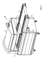
- the Fig. 2 shows a schematic section of the chamber belt machine 100.
- the lid 5 is provided with a driver 6, which is provided at the bottom of the lid 5 and extends substantially as a square profile into the plane or out of her over the entire length of the chamber 4 ,
- the lid 5 forms with the lower part 12, the chamber 4.
- the bag 13 is provided, in which a product 14 is located.
- the bag 13 has a bag neck 15 which extends in the chamber 4 in the direction of the driver 6.
- a sealing device 7 and a cutting device 8 are provided, which extend in the region of the bag neck 15 in the chamber 4 inside.
- the sealing device 7 and the cutting device 8 cooperate with an abutment 11, which is provided on the lower part 12 and extends over the entire length of the chamber 4 in the drawing plane in and out of her.
- the blow-off assembly 45 according to the invention is shown schematically. The abutment 11 and the blow-off assembly 45 according to the invention will be described later, in particular with reference to FIG FIGS. 4 and 5 , described in more detail.
- the sealing device 7 and the cutting device 8 can be lowered together or independently of each other.
- a trigger 10 is provided in addition to the lower part 12, which is designed as a suction duct and extending over the entire length of the chamber 4 in the drawing plane and out of her.
- the top of the trigger 10 is located substantially at the level of the top of the base 12.
- a gap 16 in the front view of the chamber belt machine is in the upper right area of the trigger 10, a gap 16 (see Fig. 7d - 7i ), which is closed by the lower surface of the driver 6 when the lid 5 is lowered or closed.
- the gap 16 is closed by a protective frame 9 which extends substantially into the plane of the drawing or out of it over the entire length of the chamber 4.
- the protective frame 9 has in the Fig. 2 the shape of a staircase from bottom left to top right.
- a first guard plate 91 is disposed substantially parallel to the ground and partially closes the gap 16 (see FIG Fig. 7d - 7i ).
- a second guard plate 92 joins thereto and extends upwardly substantially orthogonal to the ground.
- a third protective frame plate 93 extends at the top End of the second protective frame plate 92 substantially parallel to the ground to the right.
- the first protective frame plate 91 is located at the lowered lid 5 at the same level as the lower surface and the lower edge of the driver. 6
- a compressed air device 17 is provided. This is optionally provided to provide compressed air for removing the cut-off bag necks 15, in addition to the compressed air flow generated by the blow-off assembly 45, as will be described later.
- a suction device 18 by means of a solid arrow in the trigger 10 shown. Through this, the separated bag necks 15 can be sucked into the trigger and removed along the trigger 10.
- holes 19 are provided on the front of the trigger, so-called failed air holes whose function will be described in more detail below.
- the holes 19 are not limited to the shape shown, but rather a single bore 19 or more holes or openings may be provided of any shape.
- the provision of the compressed air device 17, the suction device 18 and the holes 19 is not absolutely necessary.
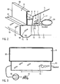
- the Fig. 3 shows a schematic front view of the device according to the Fig. 2 , According to the Fig. 3 the suction device 18 is arranged outside of the trigger 10. The bag necks 15 are in the Fig. 3 sucked out of the trigger 10 in the direction of the solid arrow of the suction device 18.
- a blow-off device which is functionally connected to the trigger 10, in order to blow the bag necks 15 out of the trigger 10 with the aid of compressed air. Through the holes 19 it comes even without a blow-off, but only through the suction device 18 to form an air flow through the trigger 10th
- the abutment 11 comprises a counter-pressure plate 20, on which, as will be explained later, a sealing and a cutting process take place in order to close the bag 13 and separate the bag neck 15.
- the blow-off assembly 45 includes a housing 46 having a surface 47 from which a blow-off element 22 protrudes.
- the blow-off element 22 comprises a blow-off strip 23 arranged over the entire width of the blow-off assembly 45.
- the blow-off strip 23 comprises equidistantly spaced air openings 24 through which compressed air can be flowed from the blow-off strip 23.
- Attached to the blow-off assembly 45 is a ramp section 25 which is primarily bolted to the housing 46.
- the Fig. 4 also shows a Abblasw 23 'with an air opening 24'.
- the blow-off assembly 45 may comprise at least one, but primarily a group of blow-off pins 23 '.
- the Abblasw 23 ' is arranged movably in the counter-pressure plate 20. In a group of Abblaswen 23 'they can be equidistant over the width of the Abblasbauè 45 provided.
- the Abblasstatt 23 ' has a rotationally symmetrical shape.
- the Abblasw 23 ' comprises a rotation, not shown, which ensures that this does not twist in a movement between the first and the second position. This makes it possible to maintain a desired orientation of the air opening 24 '.
- the shows Fig. 4 a cap 49, which is laterally releasably attached to the housing 46.
- an operator can remove the blow-off strip 23 from the guide portion 29 of the housing 46, for example, for cleaning.
- the cap 49 may be provided on both sides of the housing 46.
- the Fig. 5 shows the Abblasbauè 45 according to the invention in section A - A according to the Fig. 4 ,
- the blow-off strip 23 is in a first position in which it is sunk in the housing 46 in such a way that it is flush with the surface 47 of the housing 46.
- the ramp section 25 is arranged, which ensures that the separated bag necks 15 can be well removed from the Abblasbauè and the abutment 11 and not behind it on the lower part 12 of the packaging device according to the Fig. 2 to lie down.
- the counter-pressure plate 20 of Fig. 5 includes a surface 21, and further includes a cutting opening 26 and a sealing member 27 disposed adjacent thereto.
- the cutting apparatus 8 shown in Figure 2 moves into the cutting opening 26 to receive the excess bag neck 15 separate.
- the in the FIG. 2 Sealing device shown from above on the sealing element 27 On the sealing member 27 is a band 28, preferably a Teflon tape arranged. By the band 28, it is possible to prevent the packaging material from sticking to the abutment 11 by the sealing.
- the blow-off strip 23 is arranged in a guide section 29 of the housing 46.
- the counter-pressure plate housing 46 includes a compressed air port 30 through which compressed air in the guide portion 29 can be fed.
- a first and a second stopper 31, 32 are formed to hold the blow-off strip 23 in the guide portion 29 when they are between the first and a second position (see Fig. 6 ) emotional.
- the blow-off strip 23 comprises a vertically oriented leg 33 with a channel 34 formed therein.
- an inlet 41 is also provided which leads into the channel 34.
- From the vertical leg 33 extends laterally a flange 35 which in the Fig. 5 is shown in section.
- the vertical leg 33 with the channel 34 and the flange 35 extending from the vertical leg 33 can be produced, for example, by a bending process.
- a sealing member 37 is arranged as a round cord seal, which seen from the plan view extends around on the flange 35 so that it seals the guide portion 29 when the blow-off 23 is in the second position, in which the flange 35 upwards against the first and second stops 31, 32 presses.
- the sealing element 37 prevents compressed air from the housing 46 penetrates. In addition, it can be prevented that there is an abrupt, loud shock when the blow-off 23 from the in the Fig. 5 shown first position in the in the Fig. 6 shown second position moves.
- An upper portion of the vertical leg 33 is disposed in an opening 39 of the housing 46.
- the vertical leg 33 of the blow-off strip 23 can through the opening 39 of the in Fig. 5 shown position in the position described below Fig. 6 method.
- FIG. 5 a sectional view through the in the Fig. 4 as an alternative to the blow-off 23 shown Abblasw 23 'be. If a plurality of Abblaswe 23 'are provided, they can move synchronously through the opening 39 of the housing 46 between the first and the subsequently explained second position. In this case, for each of the Abblaslixe 23 'each have a cylindrical opening 39 formed in the housing 46.
- the Fig. 6 shows the sectional view A - A of Fig. 4 , wherein the blow-off strip 23, or the Abblasbuild 23 ', is located in the aforementioned second position in which the vertical leg 33 projects beyond the surface 47 of the housing 46.
- the blow-off strip 23 In this position of the blow-off strip 23 is located in the guide section and in the channel 34 of the blow-off 23 compressed air, which is shown dotted. The compressed air was introduced through the pressure port 30 in the guide portion 29 and from there through the inlet 41 into the channel 34.
- blow-off assembly 45 The operation of the blow-off assembly 45 according to the invention will now be described.
- Fig. 7a) - 7j show how the blow-off assembly 45 according to the invention can be used. It is on the device according to the FIG. 2 Referenced.
- the lid 5 is in a lowered position.
- the chamber 4 is evacuated in this step (dashed arrow).
- Blow-off strip 23 is in the first position in which it is sunk in the housing 46.
- the sealing device 7 and the cutting device 8 are lowered and cooperate with the abutment 11.
- the bag 13 is sealed and cut in the product-remote area of the bag neck 15. Also during this step, the blow-off strip 23 is sunk in the housing 46.
- the severed bag neck 15 rests on the blow-off assembly 45.
- the chamber 4 is vented (dashed arrow) and sealed in the bag 13 product 14 is ready for removal.
- the schematically shown blow-off strip 23 is still in the first position, in which it is sunk in the housing 46.
- the cover 5 is raised together with the driver 6 and the sealing device 7 and the cutting device 8.
- the gap 16 opens and has a first opening width. From a predetermined opening width of the gap 16, the blow-off assembly 45 according to the invention is acted upon by compressed air, so that the blow-off strip 23 moves to the second position, in which it protrudes from the housing 46.
- the compressed air which for retracting the blow-off 23 from the in the Fig. 7c shown first position in the in the Fig. 7d shown second position, passes through the inlet 41 into the channel 34 and flows out of the air openings 24 (see FIG. 6 ) to convey the separated bag neck 15 through the opened gap 16 in the trigger 10.
- Fig. 7e is the lid 5 in a first raised position, in which the upper surface of the driver 6 in contact with the inner surface of the third protective frame plate 93 (see Fig. 2 ) of the protective frame 9, the first protective frame plate 91 (see Fig. 2 ) but still in contact with the upper surface of the trigger 10 and closes a part of the gap 16.
- the bag necks 15 are further blown by the compressed air flowing from the air openings 24 in the trigger 10, wherein they bounce partially from the second protective frame plate 92 in the trigger 10.
- the lid 5 is further raised and the protective frame 9 is by the positive connection between the driver 6 and the third protective frame plate 93 (see Fig. 2 ) also raised with.
- the gap 16 increases to a second opening width in which it is completely open.
- Larger or longer bag necks 15 can now also be blown through the gap 16 into the trigger 10 by means of the compressed air flowing out of the abutment 11. So that the bag necks 15 not blown over the gap despite lifting the frame 9 Be, a wall 40 is provided on the trigger 10 as impact protection. From this, the bag necks 15 can be derived in the trigger 10. Long bag necks 15 are usually prior to the enlargement of the gap 16 beyond this or stand on the protective frame 9 at.
- the lid 5 has reached its uppermost position, wherein the trigger 10 or the gap 16 is completely opened. Large bag necks 15 can fall due to gravity and the suction effect described above in the trigger 10 and then be transported away. By switching off the compressed air, the blow-off strip 23 returns to the first position.
- Fig. 7i closes the lid 5 again and the protective frame 9 and the first protective frame plate 91 (see Fig. 2 ) closes a part of the gap 16.
- the gap 16 has again its first opening width.
- the separated bag necks 15, which are located in the trigger 10, are sucked away or blown away supported by compressed air.
- the blow-off assembly 45 according to the invention can be used in different packaging devices and is not limited to the previously described chamber belt machine.
- the Abblasbauè 45 can also be integrated advantageously without great effort in an abutment of a sealing device.
Description
- Die vorliegende Erfindung bezieht sich auf eine Abblasbaugruppe für eine Siegeleinheit einer Verpackungsvorrichtung mit den technischen Merkmalen des Anspruchs 1 sowie auf ein Verfahren zum Beseitigen eines überschüssigen Verpackungsmaterials mit den technischen Merkmalen des Anspruchs 14.
- Aus der
DE 10 2008 015 691 B3 der Anmelderin, deren Inhalt hiermit durch Bezugnahme gänzlich einbezogen ist, sind eine Vorrichtung und ein Verfahren zum Verpacken von Produkten in Beuteln bekannt. Darin wird offenbart, dass ein Deckel im Anschluss an einen Siegelungprozess und an einen Schneidprozess angehoben wird, um einen Spalt zunächst teilweise zu einem Abzug zu öffnen, wobei abgeschnittene Beutelhälse mittels einer in der Kammerbandmaschine vorgesehenen Druckluftvorrichtung durch den Spalt in den Abzug geblasen werden. Um einen Abtransport der abgeschnittenen Beutelhälse in den Abzug zu verbessern, ist zusätzlich eine Absaugvorrichtung im Abzug vorgesehen. Durch das Anheben des Deckels kann mittels eines Mitnehmers ein Rahmenelement der Kammerbandmaschine angehoben werden, um den Spalt zum Abzug komplett zu öffnen. Dadurch ist es möglich, durch den vergrößerten Spalt auch längere Beutelhälse abzuführen. - Problematisch ist allerdings, dass die abgetrennten Beutelhälse schwer durch die in der Kammerbandmaschine vorgesehene Druckluftvorrichtung sowie durch die zusätzlich vorgesehene Absaugvorrichtung vom Widerlager entfernbar sind. Vor allem hat es sich in der Praxis herausgestellt, dass Beutelhälse zeitweise am Widerlager hängen bzw. kleben bleiben, wodurch es zu einer unerwünschten Anhäufung von abgetrennten Beutelhälsen am Widerlager in der Kammerbandmaschine kommt. Schlimmstenfalls kann es sein, dass der Spalt zum Abzug verstopft, wodurch das Risiko besteht, dass sich die Kammerbandmaschine zum Evakuieren bzw. zum Begasen nicht mehr luftdicht abgeschlossen werden kann.
- Außerdem ist es schwer zu realisieren, eine Druckluftvorrichtung derart in der Kammerbandmaschine vorzusehen, dass sich durch sie die überschüssigen Beutelhälse vom Widerlager gezielt durch den Spalt in den Abzug blasen lassen.
- Folgerichtig liegt der vorliegenden Erfindung die Aufgabe zugrunde, eine Vorrichtung bzw. ein Verfahren mittels einfacher, kostengünstiger technischer Merkmale zu schaffen, wodurch sich eine Beutelrestentfernung insbesondere bei Kammerbandmaschinen optimieren lässt.
- Diese Aufgabe wird gelöst mit den technischen Merkmalen des Anspruchs 1 bzw. durch die technischen Merkmale des Verfahrensanspruchs 13. Verbesserte Weiterbildungen der Erfindung sind durch die technischen Merkmale der Unteransprüche gegeben.
- Die Erfindung betrifft eine Abblasbaugruppe für eine Siegeleinheit einer Verpackungsvorrichtung, umfassend ein Gehäuse und mindestens ein Abblaselement. Erfindungsgemäß ist vorgesehen, dass das Abblaselement relativ zum Gehäuse zwischen einer ersten Position, in der es zumindest teilweise in dem Gehäuse versenkt ist, und einer zweiten Position bewegbar ist, in der es zumindest teilweise über eine Oberfläche des Gehäuses hinausragt.
- Die erfindungsgemäße Abblasbaugruppe bietet eine einfache und kostengünstige Lösung, um überschüssiges Verpackungsmaterial, wie beispielsweise abgetrennte Beutelhälse, zuverlässig abzutransportieren. Außerdem bietet die Abblasbaugruppe der Erfindung eine platzsparende Lösung, die ohne erheblichen konstruktiven Aufwand in einer Verpackungsmaschine, wie beispielsweise einer Kammerbandmaschine, einsetzbar ist. Bisher verwendete Druckluftvorrichtungen und/oder Absaugvorrichtungen, wie sie aus dem eingangs zitierten Stand der Technik bekannt sind, lassen sich durch die erfindungsgemäße Abblasbaugruppe wirksam und einfach ersetzen oder ergänzen.
- Vor allem hat sich die Abblasbaugruppe der Erfindung als wirksam erwiesen, um sowohl kurze als auch lange abgetrennte Beutelhälse sicher von einer Siegeleinheit zu entfernen. Die Abblasbaugruppe der Erfindung kann dies mit oder ohne Unterstützung einer zusätzlichen Druckluft- und/oder Absaugvorrichtung der eingangs beschriebenen Art tun.
- Außerdem ist es durch die erfindungsgemäße Abblasbaugruppe möglich, die abgetrennten Beutelhälse innerhalb kurzer Zeit von der Abblasbaugruppe zu entfernen. Dadurch lassen sich Verpackungszeiten durch die Verpackungsvorrichtung unter Verwendung der erfindungsgemäßen Abblasbaugruppe verbessern.
- Als besonders wirkungsvoll hat sich die erfindungsgemäße Abblasbaugruppe beim Abtransport von Beutelhälsen erwiesen, die besonders hartnäckig an der Abblasbaugruppe beziehungsweise an einem zu der Siegeleinheit gehörigen Widerlager nach dem Siegelund Trennvorgang hängen bleiben, beispielsweise weil sie auf einer Oberfläche des Widerlagers verkleben.
- Vorzugsweise ist oder umfasst das Abblaselement eine Abblasleiste oder wenigstens einen Abblasstift. Mittels der Abblasleiste ist es möglich, die abgetrennten Beutelhälse besonders gut über die gesamte Breite der Abblasbaugruppe anzuheben, so dass sich die abgetrennten Beutelhälse zuverlässig von der Oberfläche der Abblasbaugruppe lösen. Insbesondere vorteilhaft ist die Abblasleiste dann, wenn die abgetrennten Beutelhälse teilweise an der Siegeleinheit verkleben. Ein oder mehrere Abblasstifte haben den Vorteil, dass sie durch ihr verhältnismäßig geringes Eigengewicht insbesondere reaktionsschnell aus der ersten in die zweite Position verstellbar sind.
- Gemäß einer weiteren Ausführungsform der Erfindung ist vorgesehen, dass das Abblaselement bündig mit der Oberfläche des Gehäuses angeordnet ist, wenn es sich in der ersten Position befindet. Dadurch wird erreicht, dass sich das Verpackungsmaterial besonders gut über die Abblasbaugruppe schieben lässt. Insbesondere wird dadurch verhindert, dass das Verpackungsmaterial auf der Abblasbaugruppe hängen bleibt und nicht ordnungsgemäß der Siegeleinheit und/oder Schneidvorrichtung zugeführt wird.
- Besonders gut kann das Verpackungsmaterial von der Oberfläche der Abblasbaugruppe gelöst bzw. gelockert werden, wenn das Abblaselement relativ zur Oberfläche des Gehäuses orthogonal verschiebbar ist. Alternativ dazu ist es möglich, dass das Abblaselement beweglich um eine Schwenkachse angeordnet ist, um zwischen der ersten und der zweiten Position geschwenkt zu werden. Dies ist insbesondere dann günstig, um ein gewichtiges Abblaselement aus der ersten in die zweite Position zu bewegen.
- Vorteilhaft ist es auch, wenn in dem Gehäuse ein Führungsabschnitt ausgebildet ist, in dem das Abblaselement beweglich angeordnet ist. Durch den Führungsabschnitt ist es möglich, dem Abblaselement eine gewünschte Bewegungsrichtung vorzugeben, in der es sich zwischen der ersten und der zweiten Position bewegt. Schließlich ermöglicht es der Führungsabschnitt, dass das Abblaselement nicht während einer Bewegung zwischen der ersten und der zweiten Position verklemmt.
- Um das Abblaselement besonders schnell zwischen der ersten und der zweiten Position zu bewegen, umfasst das Gehäuse einen Druckluftanschluss, durch den Druckluft in den Führungsabschnitt zuleitbar ist. Dabei kann der Druckluftanschluss zentrisch oder exzentrisch relativ zum Führungsabschnitt in dem Gehäuse vorgesehen sein. Wenn der Druckluftanschluss zentrisch relativ zum Führungsabschnitt in dem Gehäuse vorgesehen ist, kann das Abblaselement besonders gleichmäßig im Führungsabschnitt zwischen der ersten und der zweiten Position verfahren, ohne dabei zu verhaken. Durch eine exzentrische Anordnung des Druckluftanschlusses ist es möglich, auf konstruktive Rahmenbedingungen Rücksicht zu nehmen, die durch eine Verpackungsvorrichtung gegeben sind, in der die erfindungsgemäße Abblasbaugruppe zum Einsatz kommt.
- Vorzugsweise weist der Führungsabschnitt eine Öffnung auf, durch die das Abblaselement hindurchragt, wenn es sich in der zweiten Position befindet. Durch die Öffnung ist es möglich, das Abblaselement im Führungsabschnitt des Geäuses zu versenken, wenn es von der zweiten in die erste Position verfährt. Außerdem kann die Öffnung derart ausgebildet sein, dass sie eine enge Führung für das Abblaselement gewährleistet, wodurch sich gleichermaßen verhindern lässt, dass Verunreinigungen durch die Öffnung in den Führungsbereich gelangen.
- Um auf besonders einfache Art und Weise zu verhindern, dass sich das Abblaselement von dem Gehäuse löst, umfasst das Gehäuse mindestens einen Anschlag, der das Abblaselement an dem Gehäuse hält, wenn sich das Abblaselement in der zweiten Position befindet.
- Weiterhin kann vorgesehen sein, dass das Abblaselement einen Einlass aufweist, durch den Luft in einen in dem Abblaselement vorgesehenen Kanal einleitbar ist. Durch den Einlass kann der Kanal gleichmäßig mit Druckluft gefüllt werden, um das Abblaselement reaktionsschnell und gleichmäßig im Führungsbereich aus der ersten in die zweite Position zu bringen.
- Damit das Abblaselement reaktionsschnell und zuverlässig, also ohne dabei zu verklemmen, zwischen der ersten und der zweiten Position bewegbar ist, ist vorzugsweise vorgesehen, dass eine Unterseite des Abblaselements eine größere Fläche aufweist als der Einlass. Vorzugsweise umfasst das Abblaselement einen Flansch, der auf seiner unteren Seite eine größere Fläche aufweist als der Einlass. An der unteren Seite kann der Flansch gleichmäßig mit Druckluft beaufschlagt werden, sodass das Abblaselement ohne zu verklemmen im Führungsabschnitt verfahren kann. Außerdem kann die obere Seite des Flansches als Anschlag dienen, um das Abblaselement sicher an das Gehäuse zu halten, und/oder der Flansch kann ein Dichtungselement tragen.
- Damit sich insbesondere nach dem Anheben des Abblaselements die überschüssigen Beutelhälse gut von der Abblasbaugruppe abtransportieren lassen, umfasst das Abblaselement vorzugsweise Luftöffnungen, durch die Luft aus dem Abblaselement strömbar ist. Vorzugsweise ist die zum Anheben des Abblaselements verwendete Druckluft erst dann durch die Luftöffnungen strömbar, wenn sich das Abblaselement in der zweiten Position befindet. Somit ist es möglich, die abgetrennten überschüssigen Beutelhälse mittels des Abblaselements zunächst mechanisch anzuheben, bevor sie mittels der aus den Luftöffnungen geströmten Druckluft von der Abblasbaugruppe weggeblasen werden.
- Gemäß einer weiteren Ausführungsform der Erfindung sind die Luftöffnungen derart ausgebildet, dass der durch sie erzeugte Luftstrom in unterschiedliche Richtungen, insbesondere nach oben und/oder nach vorne weg von der Abblasbaugruppe, leitbar ist. Dadurch gelingt es, die abgetrennten Beutelhälse besonders gut von der Abblasbaugruppe wegzublasen.
- Eine weitere Ausführungsform der Erfindung betrifft ein Widerlager mit einer Abblasbaugruppe nach einer der zuvor beschriebenen Art, wobei das Gehäuse der Abblasbaugruppe integral mit einer Gegendruckplatte des Widerlagers ausgebildet ist. Das Widerlager lässt sich zusammen mit der Abblasbaugruppe hervorragend bei einer Siegelvorrichtung einsetzen, um Beutelreste zuverlässig von dem Widerlager wegzublasen.
- Alternativ dazu ist es möglich, dass die Abblasbaugruppe an der Gegendruckplatte des Widerlagers oder allgemein an der Siegeleinheit lösbar befestigt ist, beispielsweise mittels einer Schraubenverbindung. Dies hätte den Vorteil, dass die Abblasbaugruppe, sei es für Reinigungs- oder Reparaturzwecke, einfach und schnell von dem Widerlager entfernt werden könnte. Außerdem ließe sich dadurch nach Kundenwunsch ein bereits bestehendes Widerlager durch eine erfindungsgemäße Abblasbaugruppe nachrüsten.
- Die Erfindung bezieht sich auch auf ein Verfahren zum Beseitigen eines überschüssigen Verpackungsmaterials von einer Abblasbaugruppe , die für eine in einer Verpackungsvorrichtung vorgesehene Siegeleinheit einsetzbar ist. Die Abblasbaugruppe umfasst ein Gehäuse mit einem darin beweglich angeordneten Abblaselement. Erfindungsgemäß ist vorgesehen, dass das Abblaselement mit Druckluft beaufschlagt wird, um relativ zum Gehäuse aus einer ersten Position, in der es zumindest teilweise in dem Gehäuse versenkt ist, in eine zweite Position zu verfahren, in der es zumindest teilweise über eine Oberfläche des Gehäuses ragt, so dass es das überschüssige Verpackungsmaterial anhebt. Nachdem das überschüssige Verpackungsmaterial zumindest teilweise angehoben worden ist, wird die Druckluft zumindest teilweise durch in dem Abblaselement vorgesehene Luftöffnungen ausgeströmt, um das angehobene überschüssige Verpackungsmaterial von der Abblasbaugruppe wegzublasen.
- Mittels des in der Abblasbaugruppe integrierten Abblaselements lässt sich das überschüssige Verpackungsmaterial, wie beispielsweise abgetrennte Beutelhälse, zunächst von der Abblasbaugruppe durch das Anheben lockern bzw. lösen und anschließend oder gleichzeitig durch die ausströmende Druckluft wirksam wegblasen.
- Vorzugsweise ist vorgesehen, dass das Abblaselement mit Druckluft beaufschlagt wird, während oder nachdem sich ein Deckel der Verpackungsvorrichtung aus einer geschlossenen Lage in eine offene Lage bewegt, um einen Spalt eines Abzugs zumindest teilweise zu öffnen. Dadurch ist es möglich, das mittels des Abblaselements abtransportierte überschüssige Verpackungsmaterial durch den Spalt in den Abzug zu befördern, aus dem es von der Verpackungsvorrichtung abführbar ist.
- Gemäß einer weiteren Ausführungsform der Erfindung ist vorgesehen, dass das Abblaselement höchstens bis zu einem Zeitpunkt mit Druckluft beaufschlagt wird, zu welchem der Deckel mit einem Rahmen der Verpackungsvorrichtung in Eingriff gerät, um diesen anzuheben, so dass der Spalt komplett geöffnet wird. Dadurch wird verhindert, das überschüssige Verpackungsmaterial über den Spalt hinweg am Abzug vorbei zu blasen, wenn zusätzlich der Rahmen angehoben wird.
- Alternativ ist es allerdings auch möglich, das Abblaselement auch nach einem Zeitpunkt mit Druckluft zu beaufschlagen, zu welchem der Deckel mit dem Rahmen der Verpackungsvorrichtung in Eingriff gerät, um diesen anzuheben, so dass der Spalt komplett geöffnet wird. Bei dieser Ausführungsform ist allerdings eine zusätzliche Wand als Prallschutz vorgesehen, die derart angeordnet ist, dass die von der Abblasbaugruppe weggeblasenen Beutelhälse gegen sie fliegen und von ihr durch den komplett geöffneten Spalt
- in den Abzug abprallen. Dadurch ist es möglich, besonders große Verpackungsmaterialreste von der Abblasbaugruppe zuverlässig durch den komplett geöffneten Spalt in den Abzug zu transportieren.
- Die erfindungsgemäße Abblasbaugruppe, dessen Verwendung in einer Verpackungsvorrichtung sowie ein Verfahren gemäß der Erfindung werden anhand der folgenden Figuren genauer erläutert. Dabei zeigen:
- Fig. 1
- eine Kammerbandmaschine, in der die erfindungsgemäße Abblasbaugruppe anwendbar ist bzw. mit der sich das erfindungsgemäße Verfahren durchführen lässt,
- Fig. 2
- eine Verpackungsvorrichtung mit der erfindungsgemäßen Abblasbaugruppe zum Beseitigen von Beutelhälsen, wobei die Abblasbaugruppe integral mit einem Widerlager ausbildet ist,
- Fig. 3
- eine schematische Seitenansicht der Verpackungsvorrichtung aus
Figur 2 , - Fig. 4
- die erfindungsgemäße Abblasbaugruppe, die an einem Widerlager einer Siegelvorrichtung integral ausgebildet ist,
- Fig. 5
- eine Seitenansicht der
Fig. 4 im Schnitt A - A, wobei sich das Abblaselement in einer ersten Position befindet, - Fig. 6
- eine Seitenansicht der
Fig. 4 im Schnitt A - A, wobei sich das Abblaselement in einer zweiten Position befindet, und - Fig. 7a) - 7j)
- Verfahrensschritte gemäß der Erfindung, wobei in der gezeigten Verpackungsvorrichtung die erfindungsgemäße Abblasbaugruppe integral mit einem Widerlager ausgebildet ist.
- Die
Fig. 1 zeigt eine schematische Ansicht einer Kammerbandmaschine 100 mit einem Förderband 1, einem Gestell 2, einem Auflegebereich 3, einer Kammer 4 und einem Deckel 5. Die Kammer 4 wird durch den Deckel 5 zusammen mit einem Unterteil 12 gebildet, wobei sich der Deckel 5 beispielsweise motorisch betrieben automatisch öffnet oder manuell öffnen lässt, um beispielsweise zu evakuierende bzw. zu versiegelnde Beutel 13 (sieheFig. 2 ) aufzunehmen, die durch das Förderband 1 automatisch zugeführt werden, und der sich anschließend automatisch schließt, um die Kammer 4 zu bilden. - Die
Fig. 2 zeigt einen schematischen Ausschnitt der Kammerbandmaschine 100. Der Deckel 5 ist mit einem Mitnehmer 6 versehen, der am unteren Rand des Deckels 5 vorgesehen ist und sich im Wesentlichen als Vierkantprofil in die Zeichenebene hinein bzw. aus ihr heraus über die gesamte Länge der Kammer 4 erstreckt. Der Deckel 5 bildet mit dem Unterteil 12 die Kammer 4. In der Kammer 4 ist der Beutel 13 vorgesehen, in dem sich ein Produkt 14 befindet. Der Beutel 13 weist einen Beutelhals 15 auf, der sich in der Kammer 4 in Richtung des Mitnehmers 6 erstreckt. An der Innenseite des Deckels 5 sind eine Siegelvorrichtung 7 und eine Schneidvorrichtung 8 vorgesehen, die sich im Bereich des Beutelhalses 15 in die Kammer 4 hinein erstrecken. Die Siegelvorrichtung 7 und die Schneidvorrichtung 8 wirken mit einem Widerlager 11 zusammen, das auf dem Unterteil 12 vorgesehen ist und sich über die gesamte Länge der Kammer 4 in die Zeichenebene hinein bzw. aus ihr heraus erstreckt. Neben dem Widerlager 11 ist schematisch die erfindungsgemäße Abblasbaugruppe 45 gezeigt. Das Widerlager 11 sowie die erfindungsgemäße Abblasbaugruppe 45 werden später, insbesondere anhand derFiguren 4 und5 , genauer beschrieben. Die Siegelvorrichtung 7 und die Schneidvorrichtung 8 sind gemeinsam bzw. unabhängig voneinander absenkbar. - Weiterhin ist neben dem Unterteil 12 ein Abzug 10 vorgesehen, der als Absaugschacht ausgebildet ist und sich über die gesamte Länge der Kammer 4 in die Zeichenebene hinein bzw. aus ihr heraus erstreckt. Die Oberseite des Abzugs 10 befindet sich im Wesentlichen auf dem Niveau der Oberseite des Unterteils 12. In der Vorderansicht der Kammerbandmaschine ist im rechten oberen Bereich des Abzugs 10 ein Spalt 16 (siehe
Fig. 7d - 7i ) vorgesehen, der bei abgesenktem bzw. geschlossenem Deckel 5 durch die untere Fläche des Mitnehmers 6 verschlossen ist. Außerdem ist der Spalt 16 durch einen Schutzrahmen 9 verschlossen, der sich im Wesentlichen in die Zeichenebene hinein bzw. aus ihr heraus über die gesamte Länge der Kammer 4 erstreckt. Der Schutzrahmen 9 hat in derFig. 2 die Form einer Treppenstufe von links unten nach rechts oben. Eine erste Schutzrahmenplatte 91 ist im Wesentlichen parallel zum Boden angeordnet und verschließt zum Teil den Spalt 16 (sieheFig. 7d - 7i ). Eine zweite Schutzrahmenplatte 92 schließt sich daran an und erstreckt sich im Wesentlichen orthogonal zum Boden nach oben. Daran anschließend erstreckt sich eine dritte Schutzrahmenplatte 93 am oberen Ende der zweiten Schutzrahmenplatte 92 im Wesentlichen parallel zum Boden nach rechts. Die erste Schutzrahmenplatte 91 befindet sich bei abgesenktem Deckel 5 auf demselben Niveau, wie die untere Fläche bzw. die untere Kante des Mitnehmers 6. - Weiterhin ist in der
Fig. 2 eine Druckluftvorrichtung 17 vorgesehen. Diese ist optional vorgesehen, um zusätzlich zum durch die Abblasbaugruppe 45 erzeugten Druckluftstrom, wie es später beschrieben wird, Druckluft zum Beseitigen der abgeschnittenen Beutelhälse 15 zu liefern. Schließlich ist in derFig. 2 eine Absaugvorrichtung 18 mittels einem durchgezogenen Pfeil im Abzug 10 dargestellt. Durch diese können die abgetrennten Beutelhälse 15 in den Abzug gesogen werden sowie entlang des Abzugs 10 abtransportiert werden. Für einen verbesserten Abtransport der Beutelhälse 15 aus dem Abzug 10 sind an der Vorderseite des Abzugs 10 Bohrungen 19 vorgesehen, sogenannte Fehlluftbohrungen, deren Funktion nachfolgend näher beschrieben wird. Die Bohrungen 19 sind nicht auf die gezeigte Form beschränkt, vielmehr kann eine einzige Bohrung 19 oder mehrere Bohrungen bzw. Öffnungen beliebiger Form vorgesehen sein. Für einen effektiven Abtransport der abgetrennten Beutelhälse 15 von der erfindungsgemäßen Abblasbaugruppe 45 ist das Vorsehen der Druckluftvorrichtung 17, der Absaugvorrichtung 18 sowie der Bohrungen 19 jedoch nicht zwingend notwendig. - Die
Fig. 3 zeigt eine schematische Vorderansicht der Vorrichtung gemäß derFig. 2 . Gemäß derFig. 3 ist die Absaugvorrichtung 18 außerhalb des Abzugs 10 angeordnet. Die Beutelhälse 15 werden in derFig. 3 in Richtung des durchgezogenen Pfeils von der Absaugvorrichtung 18 aus dem Abzug 10 herausgesaugt. Alternativ zur Absaugvorrichtung 18 kann jedoch auch eine mit dem Abzug 10 funktional verbundene Abblasvorrichtung vorgesehen sein, um die Beutelhälse 15 mit Hilfe von Druckluft aus dem Abzug 10 herauszublasen. Durch die Bohrungen 19 kommt es auch ohne eine Abblasvorrichtung, sondern lediglich durch die Absaugvorrichtung 18 zur Bildung einer Luftströmung durch den Abzug 10. - In der
Fig. 4 ist die erfindungsgemäße Abblasbaugruppe 45 integral in dem Widerlager 11 verbaut. Das Widerlager 11 umfasst eine Gegendruckplatte 20, auf der, wie später erläutert wird, ein Siegel- sowie ein Schneidvorgang stattfinden, um den Beutel 13 zu verschließen und den Beutelhals 15 abzutrennen. - Die Abblasbaugruppe 45 umfasst ein Gehäuse 46 mit einer Oberfläche 47, von der ein Abblaselement 22 hervorsteht. Gemäß der
Fig. 4 ist das Abblaselement 22 eine über die gesamte Breite der Abblasbaugruppe 45 angeordnete Abblasleiste 23. Die Abblasleiste 23 umfasst äquidistant zueinander beabstandete Luftöffnungen 24, durch die Druckluft aus der Abblasleiste 23 strömbar ist. An der Abblasbaugruppe 45 ist ein Rampenabschnitt 25 befestigt, der an das Gehäuse 46 vornehmlich angeschraubt ist. - Die
Fig. 4 zeigt auch einen Abblasstift 23' mit einer Luftöffnung 24'. Die erfindungsgemäße Abblasbaugruppe 45 kann alternativ zur Abblasleiste 23 zumindest einen, vornehmlich jedoch eine Gruppe von Abblasstiften 23', umfassen. Der Abblasstift 23' ist in der Gegendruckplatte 20 beweglich angeordnet. Bei einer Gruppe von Abblasstiften 23' können diese äquidistant über die Breite der Abblasbaugruppe 45 vorgesehen sein. Der Abblasstift 23' hat eine rotationssymmetrische Form. Ebenso umfasst der Abblasstift 23' eine nicht gezeigte Verdrehsicherung, welche dafür sorgt, dass sich dieser bei einer Bewegung zwischen der ersten und der zweiten Position nicht verdreht. Dadurch ist es möglich, eine gewünschte Orientierung der Luftöffnung 24' beizubehalten. - Schließlich zeigt die
Fig. 4 eine Abdeckkappe 49, die seitlich am Gehäuse 46 lösbar befestigt ist. Durch Abnehmen der Abdeckkappe 49 kann ein Bediener die Abblasleiste 23 aus dem Führungsabschnitt 29 des Gehäuses 46, beispielsweise zum Reinigen, herausnehmen. Die Abdeckkappe 49 kann beidseitig am Gehäuse 46 vorgesehen sein. - Die
Fig. 5 zeigt die erfindungsgemäße Abblasbaugruppe 45 im Schnitt A - A gemäß derFig. 4 . In derFig. 5 befindet sich die Abblasleiste 23 in einer ersten Position, in der sie derart in dem Gehäuse 46 versenkt ist, dass sie mit der Oberfläche 47 des Gehäuses 46 bündig angeordnet ist. Neben dem Gehäuse 46 ist der Rampenabschnitt 25 angeordnet, welcher dafür sorgt, dass die abgetrennten Beutelhälse 15 von der Abblasbaugruppe sowie vom Widerlager 11 gut abtransportiert werden können und nicht dahinter auf dem Unterteil 12 der Verpackungsvorrichtung gemäß derFig. 2 liegen bleiben. - Die Gegendruckplatte 20 der
Fig. 5 umfasst eine Oberfläche 21 und des Weiteren eine Schneidöffnung 26 sowie ein daneben angeordnetes Siegelelement 27. Während des Schneidvorgangs, um die Beutelhälse 15 vom Beutel 13 abzutrennen, fährt die in der Figur 2 gezeigte Schneidvorrichtung 8 in die Schneidöffnung 26 hinein, um den überflüssigen Beutelhals 15 abzutrennen. Um das Produkt 14 im Beutel 13 einzuschließen, drückt die in derFigur 2 gezeigte Siegelvorrichtung von oben auf das Siegelelement 27. Auf dem Siegelelement 27 ist ein Band 28, vorzugsweise ein Teflonband, angeordnet. Durch das Band 28 ist es möglich, zu verhindern, dass das Verpackungsmaterial auf dem Widerlager 11 durch das Versiegeln kleben bleibt. - Gemäß der
Fig. 5 ist die Abblasleiste 23 in einem Führungsabschnitt 29 des Gehäuses 46 angeordnet. Außerdem umfasst das Gegendruckplatte Gehäuse 46 einen Druckluftanschluss 30, durch den Druckluft in den Führungsabschnitt 29 zuleitbar ist. Auf der Oberseite des Gehäuses 46 sind ein erster und ein zweiter Anschlag 31, 32 ausgebildet, um die Abblasleiste 23 im Führungsabschnitt 29 zu halten, wenn sie sich zwischen der ersten und einer zweiten Position (sieheFig. 6 ) bewegt. - Gemäß der
Fig. 5 umfasst die Abblasleiste 23 einen vertikal ausgerichteten Schenkel 33 mit einem darin ausgebildeten Kanal 34. In der Abblasleiste 23 ist außerdem ein Einlass 41 vorgesehen, der in den Kanal 34 führt. Vom vertikalen Schenkel 33 erstreckt sich seitlich ein Flansch 35, der in derFig. 5 im Schnitt dargestellt ist. Der vertikale Schenkel 33 mit dem Kanal 34 sowie der sich vom vertikalen Schenkel 33 erstreckende Flansch 35 können beispielsweise durch einen Biegeprozess hergestellt werden. - Auf dem Flansch 35 ist ein Dichtelement 37 als Rundschnurdichtung angeordnet, welche aus der Draufsicht gesehen ringsherum auf dem Flansch 35 verläuft, sodass sie den Führungsabschnitt 29 abdichtet, wenn die Abblasleiste 23 in der zweiten Position ist, in welcher der Flansch 35 nach oben gegen den ersten und den zweiten Anschlag 31, 32 drückt.
- Das Dichtelement 37 verhindert, dass Druckluft aus dem Gehäuse 46 ausdringt. Außerdem kann damit verhindert werden, dass es zu einem abrupten, lauten Stoß kommt, wenn die Abblasleiste 23 aus der in der
Fig. 5 gezeigten ersten Position in die in derFig. 6 gezeigten zweiten Position verfährt. - Ein oberer Abschnitt des vertikalen Schenkels 33 ist in einer Öffnung 39 des Gehäuses 46 angeordnet. Der vertikale Schenkel 33 der Abblasleiste 23 kann durch die Öffnung 39 aus der in der
Fig. 5 gezeigten Position in die Position der nachfolgend beschriebenenFig. 6 verfahren. - Ebenso gut könnte die
Fig. 5 eine Schnittdarstellung durch den in derFig. 4 als Alternative zur Abblasleiste 23 gezeigten Abblasstift 23' sein. Falls mehrere Abblasstifte 23' vorgesehen sind, können diese synchron durch die Öffnung 39 des Gehäuses 46 zwischen der ersten und der anschließend erläuterten zweiten Position verfahren. Dabei ist für jeden der Abblasstifte 23' jeweils eine zylindrische Öffnung 39 in dem Gehäuse 46 ausgebildet. - Die
Fig. 6 zeigt die Schnittansicht A - A derFig. 4 , wobei sich die Abblasleiste 23, bzw. der Abblasstift 23', in der zuvor erwähnten zweiten Position befindet, in der der vertikale Schenkel 33 über die Oberfläche 47 des Gehäuses 46 hinausragt. In dieser Position der Abblasleiste 23 befindet sich im Führungsabschnitt sowie im Kanal 34 der Abblasleiste 23 Druckluft, welche gepunktet dargestellt ist. Die Druckluft wurde durch den Druckanschluss 30 in den Führungsabschnitt 29 und von dort durch den Einlass 41 in den Kanal 34 eingeleitet. - In der
Fig. 6 drückt das Dichtelement 37 jeweils gegen eine Unterseite des ersten sowie des zweiten Anschlags 31, 32. Spätestens wenn sich die Abblasleiste 23 in der zweiten Position gemäß derFig. 6 befindet, verlässt die Druckluft den Kanal 34 durch die in derFig. 4 bereits gezeigten Luftöffnungen 24, 24'. Ein oder mehrere über dem Widerlager 11 abgetrennte Beutelhälse 15 können dadurch zunächst durch die Abblasleiste 23 über die Abblasbaugruppe 45 angehoben werden, um schließlich durch die aus den Luftöffnungen 24 strömende Druckluft weggeblasen zu werden. - Im Folgenden wird der Betrieb der erfindungsgemäßen Abblasbaugruppe 45 beschrieben.
- Die
Fig. 7a) - 7j ) zeigen, wie die erfindungsgemäße Abblasbaugruppe 45 zum Einsatz kommen kann. Dabei wird auf die Vorrichtung gemäß derFigur 2 Bezug genommen. - Wie in der
Fig. 7a gezeigt ist, befindet sich der Deckel 5 in einer abgesenkten Position. Die Kammer 4 wird in diesem Schritt evakuiert (gestrichelter Pfeil). Abblasleiste 23 befindet sich in der ersten Position, in welcher es in dem Gehäuse 46 versenkt ist. - Gemäß der
Fig. 7b werden die Siegelvorrichtung 7 und die Schneidvorrichtung 8 abgesenkt und wirken mit dem Widerlager 11 zusammen. Der Beutel 13 wird versiegelt und im produktfernen Bereich des Beutelhalses 15 geschnitten. Auch während dieses Schrittes ist die Abblasleiste 23 in dem Gehäuse 46 versenkt. - Gemäß der
Fig. 7c liegt der abgetrennte Beutelhals 15 auf der Abblasbaugruppe 45 auf. Die Kammer 4 wird belüftet (gestrichelter Pfeil) und das im Beutel 13 versiegelte Produkt 14 ist bereit zum Abtransport. In derFig. 7c befindet sich die schematisch dargestellte Abblasleiste 23 immer noch in der ersten Position, in welcher sie in dem Gehäuse 46 versenkt ist. - In der
Fig. 7d ist der Deckel 5 zusammen mit dem Mitnehmer 6 und der Siegelvorrichtung 7 sowie der Schneidvorrichtung 8 angehoben. Der Spalt 16 öffnet sich und weist eine erste Öffnungsweite auf. Ab einer vorbestimmten Öffnungsweite des Spaltes 16 wird die erfindungsgemäße Abblasbaugruppe 45 mit Druckluft beaufschlagt, so dass sich die Abblasleiste 23 in die zweite Position bewegt, in der sie aus dem Gehäuse 46 herausragt. Die Druckluft, welche zum Herausfahren der Abblasleiste 23 aus der in derFig. 7c gezeigten ersten Position in die in derFig. 7d gezeigte zweite Position verwendet wurde, gelangt durch den Einlass 41 in den Kanal 34 und strömt aus den Luftöffnungen 24 aus (sieheFigur 6 ), um den abgetrennten Beutelhals 15 durch den geöffneten Spalt 16 in den Abzug 10 zu befördern. Zusätzlich zu der aus den Luftöffnungen 24 geströmten Druckluft werden insbesondere kleine bzw. kurze Beutelhälse 15 durch die von der Absaugvorrichtung 18 (sieheFig. 3 ) erzeugte Sogwirkung in den Abzug 10 gesaugt. Die Sogwirkung wird durch den schmalen Spalt 16 mit der ersten Öffnungsweite verstärkt. - Gemäß der
Fig. 7e ist der Deckel 5 in einer ersten angehobenen Position, bei der die obere Fläche des Mitnehmers 6 in Kontakt mit der Innenfläche der dritten Schutzrahmenplatte 93 (sieheFig. 2 ) des Schutzrahmens 9 steht, die erste Schutzrahmenplatte 91 (sieheFig. 2 ) aber noch in Kontakt mit der oberen Fläche des Abzugs 10 steht und einen Teil des Spaltes 16 verschließt. Die Beutelhälse 15 werden weiterhin durch die aus den Luftöffnungen 24 strömende Druckluft in den Abzug 10 geblasen, wobei sie teilweise von der zweiten Schutzrahmenplatte 92 in den Abzug 10 abprallen. - Wie es durch die
Fig. 7f gezeigt wird, wird der Deckel 5 weiter angehoben und der Schutzrahmen 9 wird durch die formschlüssige Verbindung zwischen dem Mitnehmer 6 und der dritten Schutzrahmenplatte 93 (sieheFig. 2 ) ebenfalls mit angehoben. Auf diese Weise vergrößert sich der Spalt 16 auf eine zweite Öffnungsweite, in der er komplett geöffnet ist. Es können nun auch größere bzw. längere Beutelhälse 15 mittels der aus dem Widerlager 11 strömenden Druckluft durch den Spalt 16 in den Abzug 10 geblasen werden. Damit die Beutelhälse 15 trotz Anheben des Rahmens 9 nicht über den Spalt hinweggeblasen werden, ist auf dem Abzug 10 eine Wand 40 als Prallschutz vorgesehen. Von dieser können die Beutelhälse 15 in den Abzug 10 abgeleitet werden. Lange Beutelhälse 15 stehen üblicherweise schon vor der Vergrößerung des Spalts 16 über diesen hinaus bzw. stehen am Schutzrahmen 9 an. - In der
Fig. 7g hat der Deckel 5 seine oberste Position erreicht, wobei der Abzug 10 bzw. der Spalt 16 vollständig geöffnet ist. Große Beutelhälse 15 können aufgrund der Schwerkraft und der oben beschriebenen Sogwirkung in den Abzug 10 fallen und anschließend abtransportiert werden. Durch Abschalten der Druckluft kehrt die Abblasleiste 23 in die erste Position zurück. - Gemäß der
Fig. 7h werden die während der vorigen Verfahrensschritte gezeigten Produkte 14 abtransportiert und neue zu versiegelnde mit Produkten 14 befüllte Beutel 13 sind in die Kammer 4 befördert worden. - In der
Fig. 7i schließt sich der Deckel 5 wieder und der Schutzrahmen 9 bzw. die erste Schutzrahmenplatte 91 (sieheFig. 2 ) verschließt einen Teil des Spalts 16. Der Spalt 16 weist nun wieder seine erste Öffnungsweite auf. Die abgetrennten Beutelhälse 15, die sich im Abzug 10 befinden, werden abgesaugt bzw. druckluftunterstützt weggeblasen. - In der
Fig. 7j verschließen der Schutzrahmen 9 und der Deckel 5 den Spalt 16 vollständig. Die Vorrichtung befindet sich wieder in ihrer Ausgangsstellung (sieheFig. 7a ). Das Verfahren beginnt von Neuem mit der Evakuierung der Kammer 4. - Die erfindungsgemäße Abblasbaugruppe 45 lässt sich in unterschiedlichen Verpackungsvorrichtungen verwenden und ist nicht auf die zuvor beschriebene Kammerbandmaschine beschränkt. Die Abblasbaugruppe 45 lässt sich außerdem ohne großen Aufwand vorteilhaft in einem Widerlager einer Siegelvorrichtung integrieren.
Claims (16)
- Abblasbaugruppe (45) für eine Siegeleinheit (7) einer Verpackungsvorrichtung (100), umfassend ein Gehäuse (46) und mindestens ein Abblaselement (22), das relativ zum Gehäuse (46) zwischen einer ersten Position, in der es zumindest teilweise in dem Gehäuse (46) versenkt ist, und einer zweiten Position bewegbar ist, in der es zumindest teilweise über eine Oberfläche (47) des Gehäuses (46) hinausragt.
- Abblasbaugruppe nach Anspruch 1, dadurch gekennzeichnet, dass das Abblaselement (22) eine Abblasleiste (23) oder wenigstens einen Abblasstift (23') umfasst.
- Abblasbaugruppe nach Anspruch 1 oder 2, dadurch gekennzeichnet, dass das Abblaselement (22) bündig mit der Oberfläche (47) des Gehäuses (46) angeordnet ist, wenn es sich in der ersten Position befindet.
- Abblasbaugruppe nach einem der vorigen Ansprüche, dadurch gekennzeichnet, dass das Abblaselement (22) relativ zur Oberfläche (47) des Gehäuses (46) orthogonal verschiebbar ist.
- Abblasbaugruppe nach einem der vorigen Ansprüche, dadurch gekennzeichnet, dass in dem Gehäuse (46) ein Führungsabschnitt (29) ausgebildet ist, in dem das Abblaselement (22) beweglich angeordnet ist.
- Abblasbaugruppe nach Anspruch 5, dadurch gekennzeichnet, dass das Gehäuse (46) einen Druckluftanschluss (30) umfasst, durch den Druckluft in den Führungsabschnitt (29) zuleitbar ist.
- Abblasbaugruppe nach Anspruch 5 oder 6, dadurch gekennzeichnet, dass der Führungsabschnitt (29) eine Öffnung (39) aufweist, durch die das Abblaselement (22) hindurchragt, wenn es sich in der zweiten Position befindet.
- Abblasbaugruppe nach einem der vorigen Ansprüche, dadurch gekennzeichnet, dass das Gehäuse (46) mindestens einen Anschlag (32, 33) umfasst, der das Abblaselement (22) an das Gehäuse (46) hält, wenn sich das Abblaselement (22) in der zweiten Position befindet.
- Abblasbaugruppe nach einem der vorigen Ansprüche, dadurch gekennzeichnet, dass das Abblaselement (22) einen Einlass (41) aufweist, durch den Luft in einen in dem Abblaselement (22) vorgesehenen Kanal (34) einleitbar ist.
- Abblasbaugruppe nach Anspruch 9, dadurch gekennzeichnet, dass eine Unterseite des Abblaselements (22) eine größere Fläche aufweist als der Einlass (41).
- Abblasbaugruppe nach einem der vorigen Ansprüche, dadurch gekennzeichnet, dass das Abblaselement (22) Luftöffnungen (24) umfasst, durch die Luft aus dem Abblaselement (22) strömbar ist.
- Abblasbaugruppe nach einem der vorigen Ansprüche, dadurch gekennzeichnet, dass das Abblaselement (22) mindestens ein Dichtelement (37) aufweist, um einen abrupten Stoß des Abblaselements (22) gegen das Gehäuse (46) zu verhindern.
- Widerlager (11) für eine Siegeleinheit (7) einer Verpackungsvorrichtung (100), umfassend eine Abblasbaugruppe (45) nach einem der vorigen Ansprüche, wobei das Gehäuse (46) der Abblasbaugruppe (45) integral mit einer Gegendruckplatte (20) des Widerlagers (11) ausgebildet ist.
- Verfahren zum Beseitigen eines überschüssigen Verpackungsmaterials (15) von einer Abblasbaugruppe (45), die für eine in einer Verpackungsvorrichtung (100) vorgesehenen Siegeleinheit (7) einsetzbar ist, welche ein Gehäuse (46) mit einem darin beweglich angeordneten Abblaselement (22) umfasst, wobei das Abblaselement (22) mit Druckluft beaufschlagt wird, um relativ zum Gehäuse (46) aus einer ersten Position, in der es zumindest teilweise in dem Gehäuse (46) versenkt ist, in eine zweite Position zu verfahren, in der es zumindest teilweise über eine Oberfläche (47) des Gehäuses (46) ragt, so dass es das überschüssige Verpackungsmaterial (15) anhebt, und wobei die Druckluft zumindest teilweise durch in dem Abblaselement (22) vorgesehene Luftöffnungen (24) ausgeströmt wird, um das angehobene überschüssige Verpackungsmaterial (15) von der Abblasbaugruppe (45) wegzublasen.
- Verfahren nach Anspruch 14, dadurch gekennzeichnet, dass das Abblaselement (22) mit Druckluft beaufschlagt wird, während oder nachdem sich ein Deckel (5) der Verpackungsvorrichtung (100) aus einer geschlossenen Lage in eine offene Lage bewegt, um einen Spalt (16) eines Abzugs (10) teilweise zu öffnen.
- Verfahren nach Anspruch 15, dadurch gekennzeichnet, dass das Abblaselement (22) höchstens bis zu einem Zeitpunkt mit Druckluft beaufschlagt wird, zu welchem der Deckel (5) mit einem Rahmen (9) der Verpackungsvorrichtung (100) in Eingriff gerät, um diesen anzuheben, so dass der Spalt (16) komplett geöffnet wird.
Priority Applications (3)
| Application Number | Priority Date | Filing Date | Title |
|---|---|---|---|
| EP12003000.2A EP2657005B1 (de) | 2012-04-27 | 2012-04-27 | Abblasbaugruppe für eine Siegeleinheit einer Verpackungsvorrichtung |
| US13/870,894 US9403195B2 (en) | 2012-04-27 | 2013-04-25 | Blowing assembly for a sealing unit of a packaging device |
| CN201310156272.6A CN103373499B (zh) | 2012-04-27 | 2013-04-28 | 包装设备的密封单元用的吹气组件 |
Applications Claiming Priority (1)
| Application Number | Priority Date | Filing Date | Title |
|---|---|---|---|
| EP12003000.2A EP2657005B1 (de) | 2012-04-27 | 2012-04-27 | Abblasbaugruppe für eine Siegeleinheit einer Verpackungsvorrichtung |
Publications (2)
| Publication Number | Publication Date |
|---|---|
| EP2657005A1 EP2657005A1 (de) | 2013-10-30 |
| EP2657005B1 true EP2657005B1 (de) | 2014-06-25 |
Family
ID=46149106
Family Applications (1)
| Application Number | Title | Priority Date | Filing Date |
|---|---|---|---|
| EP12003000.2A Active EP2657005B1 (de) | 2012-04-27 | 2012-04-27 | Abblasbaugruppe für eine Siegeleinheit einer Verpackungsvorrichtung |
Country Status (3)
| Country | Link |
|---|---|
| US (1) | US9403195B2 (de) |
| EP (1) | EP2657005B1 (de) |
| CN (1) | CN103373499B (de) |
Families Citing this family (7)
| Publication number | Priority date | Publication date | Assignee | Title |
|---|---|---|---|---|
| DE102015010432B4 (de) * | 2015-08-11 | 2021-02-04 | Michatek, K.S. | Schweißbalken für Vakuumschublade sowie Vakuumschublade |
| BR122020021877B1 (pt) | 2015-09-25 | 2022-05-24 | Furukawa Mfg. Co., Ltd. | Aparelho para evacuar e vedar uma ou mais embalagens e método para posicionar uma embalagem sobre uma placa de um aparelho para evacuar e vedar a embalagem |
| IT201600129875A1 (it) * | 2016-12-22 | 2018-06-22 | Altopack Spa | Apparato di saldatura e taglio per testa di sacchetti per alimenti. |
| IT201600129946A1 (it) * | 2016-12-22 | 2018-06-22 | Altopack Spa | Macchina per il confezionamento di sacchetti per alimenti. |
| US11097695B2 (en) * | 2018-10-30 | 2021-08-24 | Waymo Llc | Non-contact cleaning system |
| ES1247635Y (es) * | 2020-04-16 | 2020-09-01 | Coalza Systems S L | Maquina carrusel para confeccionar bolsas paquete |
| DE102021111010B4 (de) | 2021-04-29 | 2023-03-30 | Multivac Sepp Haggenmüller Se & Co. Kg | Siegelmaschine zum Versiegeln von Verpackungen |
Family Cites Families (9)
| Publication number | Priority date | Publication date | Assignee | Title |
|---|---|---|---|---|
| US3699742A (en) * | 1971-02-18 | 1972-10-24 | Grace W R & Co | Apparatus for vacuum welding of plastics envelopes |
| CH686129A5 (de) * | 1992-10-21 | 1996-01-15 | Luwa Ag Zellweger | Aufsteckvorrichtung fur Garnspulen. |
| JP2585190B2 (ja) | 1994-01-27 | 1997-02-26 | 株式会社島精機製作所 | 裁断機への生地被覆シート供給装置および方法 |
| CN2281313Y (zh) * | 1997-02-03 | 1998-05-13 | 杭州市中亚包装有限公司 | 铝复合膜盖的空气分道装置 |
| CN100443372C (zh) | 2006-04-26 | 2008-12-17 | 长沙楚天科技有限公司 | 自动装药机 |
| DE102008015691B3 (de) | 2008-03-26 | 2010-04-15 | Multivac Sepp Haggenmüller Gmbh & Co. Kg | Vorrichtung und Verfahren zum Verpacken von Produkten in Beuteln |
| CN101734417B (zh) * | 2008-11-13 | 2012-12-26 | 西奎斯特盖有限责任合作公司 | 刺穿衬板的可扭弯的封闭件 |
| CN101439326A (zh) * | 2008-11-25 | 2009-05-27 | 湖南大学 | 一种凝汽器智能移动清洗机器人的高压喷水装置 |
| FI122900B (fi) * | 2010-06-15 | 2012-08-31 | Metso Paper Inc | Kuljetin päänvientinauhan kuljettamiseksi kuiturainakoneessa |
-
2012
- 2012-04-27 EP EP12003000.2A patent/EP2657005B1/de active Active
-
2013
- 2013-04-25 US US13/870,894 patent/US9403195B2/en active Active
- 2013-04-28 CN CN201310156272.6A patent/CN103373499B/zh active Active
Also Published As
| Publication number | Publication date |
|---|---|
| CN103373499B (zh) | 2015-06-24 |
| CN103373499A (zh) | 2013-10-30 |
| US9403195B2 (en) | 2016-08-02 |
| EP2657005A1 (de) | 2013-10-30 |
| US20130284214A1 (en) | 2013-10-31 |
Similar Documents
| Publication | Publication Date | Title |
|---|---|---|
| EP2657005B1 (de) | Abblasbaugruppe für eine Siegeleinheit einer Verpackungsvorrichtung | |
| EP3422494B1 (de) | Abtrennvorrichtung sowie verfahren zum abtrennen einer kabeltülle von einem kabel | |
| DE2137058A1 (de) | ||
| WO2013102682A1 (de) | Verpackungsmaschine mit einer schneidstation | |
| EP2892706B1 (de) | Vorrichtung zum absaugen von abfallprodukten einer produktionsmaschine mit einem absaugelement | |
| DE1783018C3 (de) | Anlage zum mechanischen Entfernen von Anodenblöcken von den Anodenhalterungen mit anschließender Verkleinerung der Anodenreste | |
| DE102008015691B3 (de) | Vorrichtung und Verfahren zum Verpacken von Produkten in Beuteln | |
| DE102004032826B4 (de) | Verfahren zum Herstellen von Stanzteilen | |
| DE102012217684B4 (de) | Beschneidstation | |
| DE102013208307B4 (de) | Plattenaufteilanlage | |
| DE202014101589U1 (de) | Verpackungsmaschine | |
| EP3566985B1 (de) | Trayabstapelvorrichtung mit entlastungseinrichtung | |
| EP2810880A1 (de) | Öffnungsvorrichtung für das Öffnen eines Sackabschnittts einer Folienbahn in einer Sackfüllanlage | |
| EP3539883B1 (de) | Tiefziehverpackungsmaschine mit folienumlenkung | |
| DE102005062713A1 (de) | Vorrichtung zum Separieren, insbesondere Abfördern eines Teilstapels mit mindestens einer großformatigen Platte von einem Reststapel mit einer Mehrzahl großformatiger Platten | |
| EP2776347B1 (de) | Beschickungsvorrichtung für behälterverschlüsse | |
| DE102010050877B4 (de) | Vorrichtung zum Anheben und Entleeren von Behältern mit Schüttgütern, insbesondere von Säcken mit rieselfähigen Produkten | |
| DE202014101427U1 (de) | Längstrennschweißvorrichtung mit verbesserter Austreibvorrichtung | |
| DE19642124A1 (de) | Verfahren und Vorrichtung zum Verhindern von Produktionsstörungen an Falzeinrichtungen | |
| DE102014202467A1 (de) | Vorrichtung zur Herstellung einer Gummimischung | |
| DE202013104379U1 (de) | Dämpfungsstruktur einer Vakuumformungs- Schneidemaschine | |
| EP2384637B1 (de) | Vorrichtung zum Verschliessen von schlauchförmigen Verpackungen | |
| EP2986102B1 (de) | Vorrichtung zur entnahme von silage | |
| DE2610475C3 (de) | Vorrichtung zum einzelweisen Entnehmen und Abführen von Platten | |
| EP3840894B1 (de) | Verfahren und vorrichtung zum selektiven aussondern von rieselfähigen produkten |
Legal Events
| Date | Code | Title | Description |
|---|---|---|---|
| PUAI | Public reference made under article 153(3) epc to a published international application that has entered the european phase |
Free format text: ORIGINAL CODE: 0009012 |
|
| AK | Designated contracting states |
Kind code of ref document: A1 Designated state(s): AL AT BE BG CH CY CZ DE DK EE ES FI FR GB GR HR HU IE IS IT LI LT LU LV MC MK MT NL NO PL PT RO RS SE SI SK SM TR |
|
| AX | Request for extension of the european patent |
Extension state: BA ME |
|
| 17P | Request for examination filed |
Effective date: 20131122 |
|
| RBV | Designated contracting states (corrected) |
Designated state(s): AL AT BE BG CH CY CZ DE DK EE ES FI FR GB GR HR HU IE IS IT LI LT LU LV MC MK MT NL NO PL PT RO RS SE SI SK SM TR |
|
| RIC1 | Information provided on ipc code assigned before grant |
Ipc: B08B 5/02 20060101ALI20131211BHEP Ipc: B29C 65/00 20060101AFI20131211BHEP Ipc: B65B 51/14 20060101ALI20131211BHEP Ipc: B65B 51/10 20060101ALI20131211BHEP |
|
| GRAP | Despatch of communication of intention to grant a patent |
Free format text: ORIGINAL CODE: EPIDOSNIGR1 |
|
| INTG | Intention to grant announced |
Effective date: 20140122 |
|
| GRAS | Grant fee paid |
Free format text: ORIGINAL CODE: EPIDOSNIGR3 |
|
| GRAA | (expected) grant |
Free format text: ORIGINAL CODE: 0009210 |
|
| AK | Designated contracting states |
Kind code of ref document: B1 Designated state(s): AL AT BE BG CH CY CZ DE DK EE ES FI FR GB GR HR HU IE IS IT LI LT LU LV MC MK MT NL NO PL PT RO RS SE SI SK SM TR |
|
| REG | Reference to a national code |
Ref country code: GB Ref legal event code: FG4D Free format text: NOT ENGLISH |
|
| REG | Reference to a national code |
Ref country code: CH Ref legal event code: EP Ref country code: CH Ref legal event code: NV Representative=s name: BOVARD AG, CH |
|
| REG | Reference to a national code |
Ref country code: AT Ref legal event code: REF Ref document number: 674357 Country of ref document: AT Kind code of ref document: T Effective date: 20140715 |
|
| REG | Reference to a national code |
Ref country code: IE Ref legal event code: FG4D Free format text: LANGUAGE OF EP DOCUMENT: GERMAN |
|
| REG | Reference to a national code |
Ref country code: DE Ref legal event code: R096 Ref document number: 502012000908 Country of ref document: DE Effective date: 20140814 |
|
| PG25 | Lapsed in a contracting state [announced via postgrant information from national office to epo] |
Ref country code: NO Free format text: LAPSE BECAUSE OF FAILURE TO SUBMIT A TRANSLATION OF THE DESCRIPTION OR TO PAY THE FEE WITHIN THE PRESCRIBED TIME-LIMIT Effective date: 20140925 Ref country code: CY Free format text: LAPSE BECAUSE OF FAILURE TO SUBMIT A TRANSLATION OF THE DESCRIPTION OR TO PAY THE FEE WITHIN THE PRESCRIBED TIME-LIMIT Effective date: 20140625 Ref country code: FI Free format text: LAPSE BECAUSE OF FAILURE TO SUBMIT A TRANSLATION OF THE DESCRIPTION OR TO PAY THE FEE WITHIN THE PRESCRIBED TIME-LIMIT Effective date: 20140625 Ref country code: GR Free format text: LAPSE BECAUSE OF FAILURE TO SUBMIT A TRANSLATION OF THE DESCRIPTION OR TO PAY THE FEE WITHIN THE PRESCRIBED TIME-LIMIT Effective date: 20140926 Ref country code: LT Free format text: LAPSE BECAUSE OF FAILURE TO SUBMIT A TRANSLATION OF THE DESCRIPTION OR TO PAY THE FEE WITHIN THE PRESCRIBED TIME-LIMIT Effective date: 20140625 |
|
| REG | Reference to a national code |
Ref country code: NL Ref legal event code: VDEP Effective date: 20140625 |
|
| REG | Reference to a national code |
Ref country code: LT Ref legal event code: MG4D |
|
| PG25 | Lapsed in a contracting state [announced via postgrant information from national office to epo] |
Ref country code: LV Free format text: LAPSE BECAUSE OF FAILURE TO SUBMIT A TRANSLATION OF THE DESCRIPTION OR TO PAY THE FEE WITHIN THE PRESCRIBED TIME-LIMIT Effective date: 20140625 Ref country code: HR Free format text: LAPSE BECAUSE OF FAILURE TO SUBMIT A TRANSLATION OF THE DESCRIPTION OR TO PAY THE FEE WITHIN THE PRESCRIBED TIME-LIMIT Effective date: 20140625 Ref country code: RS Free format text: LAPSE BECAUSE OF FAILURE TO SUBMIT A TRANSLATION OF THE DESCRIPTION OR TO PAY THE FEE WITHIN THE PRESCRIBED TIME-LIMIT Effective date: 20140625 Ref country code: SE Free format text: LAPSE BECAUSE OF FAILURE TO SUBMIT A TRANSLATION OF THE DESCRIPTION OR TO PAY THE FEE WITHIN THE PRESCRIBED TIME-LIMIT Effective date: 20140625 |
|
| PG25 | Lapsed in a contracting state [announced via postgrant information from national office to epo] |
Ref country code: CZ Free format text: LAPSE BECAUSE OF FAILURE TO SUBMIT A TRANSLATION OF THE DESCRIPTION OR TO PAY THE FEE WITHIN THE PRESCRIBED TIME-LIMIT Effective date: 20140625 Ref country code: SK Free format text: LAPSE BECAUSE OF FAILURE TO SUBMIT A TRANSLATION OF THE DESCRIPTION OR TO PAY THE FEE WITHIN THE PRESCRIBED TIME-LIMIT Effective date: 20140625 Ref country code: ES Free format text: LAPSE BECAUSE OF FAILURE TO SUBMIT A TRANSLATION OF THE DESCRIPTION OR TO PAY THE FEE WITHIN THE PRESCRIBED TIME-LIMIT Effective date: 20140625 Ref country code: PT Free format text: LAPSE BECAUSE OF FAILURE TO SUBMIT A TRANSLATION OF THE DESCRIPTION OR TO PAY THE FEE WITHIN THE PRESCRIBED TIME-LIMIT Effective date: 20141027 Ref country code: EE Free format text: LAPSE BECAUSE OF FAILURE TO SUBMIT A TRANSLATION OF THE DESCRIPTION OR TO PAY THE FEE WITHIN THE PRESCRIBED TIME-LIMIT Effective date: 20140625 Ref country code: RO Free format text: LAPSE BECAUSE OF FAILURE TO SUBMIT A TRANSLATION OF THE DESCRIPTION OR TO PAY THE FEE WITHIN THE PRESCRIBED TIME-LIMIT Effective date: 20140625 |
|
| PG25 | Lapsed in a contracting state [announced via postgrant information from national office to epo] |
Ref country code: NL Free format text: LAPSE BECAUSE OF FAILURE TO SUBMIT A TRANSLATION OF THE DESCRIPTION OR TO PAY THE FEE WITHIN THE PRESCRIBED TIME-LIMIT Effective date: 20140625 Ref country code: IS Free format text: LAPSE BECAUSE OF FAILURE TO SUBMIT A TRANSLATION OF THE DESCRIPTION OR TO PAY THE FEE WITHIN THE PRESCRIBED TIME-LIMIT Effective date: 20141025 Ref country code: PL Free format text: LAPSE BECAUSE OF FAILURE TO SUBMIT A TRANSLATION OF THE DESCRIPTION OR TO PAY THE FEE WITHIN THE PRESCRIBED TIME-LIMIT Effective date: 20140625 |
|
| REG | Reference to a national code |
Ref country code: DE Ref legal event code: R097 Ref document number: 502012000908 Country of ref document: DE |
|
| PG25 | Lapsed in a contracting state [announced via postgrant information from national office to epo] |
Ref country code: DK Free format text: LAPSE BECAUSE OF FAILURE TO SUBMIT A TRANSLATION OF THE DESCRIPTION OR TO PAY THE FEE WITHIN THE PRESCRIBED TIME-LIMIT Effective date: 20140625 |
|
| PLBE | No opposition filed within time limit |
Free format text: ORIGINAL CODE: 0009261 |
|
| STAA | Information on the status of an ep patent application or granted ep patent |
Free format text: STATUS: NO OPPOSITION FILED WITHIN TIME LIMIT |
|
| 26N | No opposition filed |
Effective date: 20150326 |
|
| PG25 | Lapsed in a contracting state [announced via postgrant information from national office to epo] |
Ref country code: LU Free format text: LAPSE BECAUSE OF FAILURE TO SUBMIT A TRANSLATION OF THE DESCRIPTION OR TO PAY THE FEE WITHIN THE PRESCRIBED TIME-LIMIT Effective date: 20150427 Ref country code: SI Free format text: LAPSE BECAUSE OF FAILURE TO SUBMIT A TRANSLATION OF THE DESCRIPTION OR TO PAY THE FEE WITHIN THE PRESCRIBED TIME-LIMIT Effective date: 20140625 Ref country code: MC Free format text: LAPSE BECAUSE OF FAILURE TO SUBMIT A TRANSLATION OF THE DESCRIPTION OR TO PAY THE FEE WITHIN THE PRESCRIBED TIME-LIMIT Effective date: 20140625 |
|
| REG | Reference to a national code |
Ref country code: IE Ref legal event code: MM4A |
|
| REG | Reference to a national code |
Ref country code: DE Ref legal event code: R082 Ref document number: 502012000908 Country of ref document: DE Representative=s name: GRUENECKER PATENT- UND RECHTSANWAELTE PARTG MB, DE Ref country code: DE Ref legal event code: R081 Ref document number: 502012000908 Country of ref document: DE Owner name: MULTIVAC SEPP HAGGENMUELLER SE & CO. KG, DE Free format text: FORMER OWNER: MULTIVAC SEPP HAGGENMUELLER GMBH & CO. KG, 87787 WOLFERTSCHWENDEN, DE |
|
| REG | Reference to a national code |
Ref country code: FR Ref legal event code: PLFP Year of fee payment: 5 |
|
| PG25 | Lapsed in a contracting state [announced via postgrant information from national office to epo] |
Ref country code: IE Free format text: LAPSE BECAUSE OF NON-PAYMENT OF DUE FEES Effective date: 20150427 |
|
| PG25 | Lapsed in a contracting state [announced via postgrant information from national office to epo] |
Ref country code: MT Free format text: LAPSE BECAUSE OF FAILURE TO SUBMIT A TRANSLATION OF THE DESCRIPTION OR TO PAY THE FEE WITHIN THE PRESCRIBED TIME-LIMIT Effective date: 20140625 |
|
| REG | Reference to a national code |
Ref country code: FR Ref legal event code: PLFP Year of fee payment: 6 |
|
| PG25 | Lapsed in a contracting state [announced via postgrant information from national office to epo] |
Ref country code: SM Free format text: LAPSE BECAUSE OF FAILURE TO SUBMIT A TRANSLATION OF THE DESCRIPTION OR TO PAY THE FEE WITHIN THE PRESCRIBED TIME-LIMIT Effective date: 20140625 Ref country code: BG Free format text: LAPSE BECAUSE OF FAILURE TO SUBMIT A TRANSLATION OF THE DESCRIPTION OR TO PAY THE FEE WITHIN THE PRESCRIBED TIME-LIMIT Effective date: 20140625 Ref country code: HU Free format text: LAPSE BECAUSE OF FAILURE TO SUBMIT A TRANSLATION OF THE DESCRIPTION OR TO PAY THE FEE WITHIN THE PRESCRIBED TIME-LIMIT; INVALID AB INITIO Effective date: 20120427 |
|
| PG25 | Lapsed in a contracting state [announced via postgrant information from national office to epo] |
Ref country code: BE Free format text: LAPSE BECAUSE OF NON-PAYMENT OF DUE FEES Effective date: 20150430 |
|
| REG | Reference to a national code |
Ref country code: FR Ref legal event code: PLFP Year of fee payment: 7 |
|
| PG25 | Lapsed in a contracting state [announced via postgrant information from national office to epo] |
Ref country code: MK Free format text: LAPSE BECAUSE OF FAILURE TO SUBMIT A TRANSLATION OF THE DESCRIPTION OR TO PAY THE FEE WITHIN THE PRESCRIBED TIME-LIMIT Effective date: 20140625 |
|
| PG25 | Lapsed in a contracting state [announced via postgrant information from national office to epo] |
Ref country code: AL Free format text: LAPSE BECAUSE OF FAILURE TO SUBMIT A TRANSLATION OF THE DESCRIPTION OR TO PAY THE FEE WITHIN THE PRESCRIBED TIME-LIMIT Effective date: 20140625 |
|
| P01 | Opt-out of the competence of the unified patent court (upc) registered |
Effective date: 20230404 |
|
| PGFP | Annual fee paid to national office [announced via postgrant information from national office to epo] |
Ref country code: IT Payment date: 20230428 Year of fee payment: 12 Ref country code: FR Payment date: 20230417 Year of fee payment: 12 Ref country code: DE Payment date: 20230418 Year of fee payment: 12 Ref country code: CH Payment date: 20230502 Year of fee payment: 12 |
|
| PGFP | Annual fee paid to national office [announced via postgrant information from national office to epo] |
Ref country code: TR Payment date: 20230426 Year of fee payment: 12 Ref country code: AT Payment date: 20230414 Year of fee payment: 12 |
|
| PGFP | Annual fee paid to national office [announced via postgrant information from national office to epo] |
Ref country code: GB Payment date: 20230420 Year of fee payment: 12 |