EP2657005B1 - Groupe de soufflage pour une unité d'étanchéité d'un appareil d'emballage - Google Patents
Groupe de soufflage pour une unité d'étanchéité d'un appareil d'emballage Download PDFInfo
- Publication number
- EP2657005B1 EP2657005B1 EP12003000.2A EP12003000A EP2657005B1 EP 2657005 B1 EP2657005 B1 EP 2657005B1 EP 12003000 A EP12003000 A EP 12003000A EP 2657005 B1 EP2657005 B1 EP 2657005B1
- Authority
- EP
- European Patent Office
- Prior art keywords
- blowing
- housing
- blow
- compressed air
- assembly according
- Prior art date
- Legal status (The legal status is an assumption and is not a legal conclusion. Google has not performed a legal analysis and makes no representation as to the accuracy of the status listed.)
- Active
Links
Images


Classifications
-
- B—PERFORMING OPERATIONS; TRANSPORTING
- B08—CLEANING
- B08B—CLEANING IN GENERAL; PREVENTION OF FOULING IN GENERAL
- B08B5/00—Cleaning by methods involving the use of air flow or gas flow
- B08B5/02—Cleaning by the force of jets, e.g. blowing-out cavities
-
- B—PERFORMING OPERATIONS; TRANSPORTING
- B29—WORKING OF PLASTICS; WORKING OF SUBSTANCES IN A PLASTIC STATE IN GENERAL
- B29C—SHAPING OR JOINING OF PLASTICS; SHAPING OF MATERIAL IN A PLASTIC STATE, NOT OTHERWISE PROVIDED FOR; AFTER-TREATMENT OF THE SHAPED PRODUCTS, e.g. REPAIRING
- B29C65/00—Joining or sealing of preformed parts, e.g. welding of plastics materials; Apparatus therefor
- B29C65/74—Joining or sealing of preformed parts, e.g. welding of plastics materials; Apparatus therefor by welding and severing, or by joining and severing, the severing being performed in the area to be joined, next to the area to be joined, in the joint area or next to the joint area
- B29C65/745—Joining or sealing of preformed parts, e.g. welding of plastics materials; Apparatus therefor by welding and severing, or by joining and severing, the severing being performed in the area to be joined, next to the area to be joined, in the joint area or next to the joint area using a single unit having both a severing tool and a welding tool
-
- B—PERFORMING OPERATIONS; TRANSPORTING
- B29—WORKING OF PLASTICS; WORKING OF SUBSTANCES IN A PLASTIC STATE IN GENERAL
- B29C—SHAPING OR JOINING OF PLASTICS; SHAPING OF MATERIAL IN A PLASTIC STATE, NOT OTHERWISE PROVIDED FOR; AFTER-TREATMENT OF THE SHAPED PRODUCTS, e.g. REPAIRING
- B29C65/00—Joining or sealing of preformed parts, e.g. welding of plastics materials; Apparatus therefor
- B29C65/74—Joining or sealing of preformed parts, e.g. welding of plastics materials; Apparatus therefor by welding and severing, or by joining and severing, the severing being performed in the area to be joined, next to the area to be joined, in the joint area or next to the joint area
- B29C65/749—Removing scrap
-
- B—PERFORMING OPERATIONS; TRANSPORTING
- B29—WORKING OF PLASTICS; WORKING OF SUBSTANCES IN A PLASTIC STATE IN GENERAL
- B29C—SHAPING OR JOINING OF PLASTICS; SHAPING OF MATERIAL IN A PLASTIC STATE, NOT OTHERWISE PROVIDED FOR; AFTER-TREATMENT OF THE SHAPED PRODUCTS, e.g. REPAIRING
- B29C66/00—General aspects of processes or apparatus for joining preformed parts
- B29C66/004—Preventing sticking together, e.g. of some areas of the parts to be joined
- B29C66/0042—Preventing sticking together, e.g. of some areas of the parts to be joined of the joining tool and the parts to be joined
- B29C66/0044—Preventing sticking together, e.g. of some areas of the parts to be joined of the joining tool and the parts to be joined using a separating sheet, e.g. fixed on the joining tool
-
- B—PERFORMING OPERATIONS; TRANSPORTING
- B29—WORKING OF PLASTICS; WORKING OF SUBSTANCES IN A PLASTIC STATE IN GENERAL
- B29C—SHAPING OR JOINING OF PLASTICS; SHAPING OF MATERIAL IN A PLASTIC STATE, NOT OTHERWISE PROVIDED FOR; AFTER-TREATMENT OF THE SHAPED PRODUCTS, e.g. REPAIRING
- B29C66/00—General aspects of processes or apparatus for joining preformed parts
- B29C66/01—General aspects dealing with the joint area or with the area to be joined
- B29C66/05—Particular design of joint configurations
- B29C66/10—Particular design of joint configurations particular design of the joint cross-sections
- B29C66/11—Joint cross-sections comprising a single joint-segment, i.e. one of the parts to be joined comprising a single joint-segment in the joint cross-section
- B29C66/112—Single lapped joints
- B29C66/1122—Single lap to lap joints, i.e. overlap joints
-
- B—PERFORMING OPERATIONS; TRANSPORTING
- B29—WORKING OF PLASTICS; WORKING OF SUBSTANCES IN A PLASTIC STATE IN GENERAL
- B29C—SHAPING OR JOINING OF PLASTICS; SHAPING OF MATERIAL IN A PLASTIC STATE, NOT OTHERWISE PROVIDED FOR; AFTER-TREATMENT OF THE SHAPED PRODUCTS, e.g. REPAIRING
- B29C66/00—General aspects of processes or apparatus for joining preformed parts
- B29C66/40—General aspects of joining substantially flat articles, e.g. plates, sheets or web-like materials; Making flat seams in tubular or hollow articles; Joining single elements to substantially flat surfaces
- B29C66/41—Joining substantially flat articles ; Making flat seams in tubular or hollow articles
- B29C66/43—Joining a relatively small portion of the surface of said articles
- B29C66/431—Joining the articles to themselves
- B29C66/4312—Joining the articles to themselves for making flat seams in tubular or hollow articles, e.g. transversal seams
- B29C66/43121—Closing the ends of tubular or hollow single articles, e.g. closing the ends of bags
-
- B—PERFORMING OPERATIONS; TRANSPORTING
- B29—WORKING OF PLASTICS; WORKING OF SUBSTANCES IN A PLASTIC STATE IN GENERAL
- B29C—SHAPING OR JOINING OF PLASTICS; SHAPING OF MATERIAL IN A PLASTIC STATE, NOT OTHERWISE PROVIDED FOR; AFTER-TREATMENT OF THE SHAPED PRODUCTS, e.g. REPAIRING
- B29C66/00—General aspects of processes or apparatus for joining preformed parts
- B29C66/80—General aspects of machine operations or constructions and parts thereof
- B29C66/81—General aspects of the pressing elements, i.e. the elements applying pressure on the parts to be joined in the area to be joined, e.g. the welding jaws or clamps
- B29C66/812—General aspects of the pressing elements, i.e. the elements applying pressure on the parts to be joined in the area to be joined, e.g. the welding jaws or clamps characterised by the composition, by the structure, by the intensive physical properties or by the optical properties of the material constituting the pressing elements, e.g. constituting the welding jaws or clamps
- B29C66/8122—General aspects of the pressing elements, i.e. the elements applying pressure on the parts to be joined in the area to be joined, e.g. the welding jaws or clamps characterised by the composition, by the structure, by the intensive physical properties or by the optical properties of the material constituting the pressing elements, e.g. constituting the welding jaws or clamps characterised by the composition of the material constituting the pressing elements, e.g. constituting the welding jaws or clamps
-
- B—PERFORMING OPERATIONS; TRANSPORTING
- B29—WORKING OF PLASTICS; WORKING OF SUBSTANCES IN A PLASTIC STATE IN GENERAL
- B29C—SHAPING OR JOINING OF PLASTICS; SHAPING OF MATERIAL IN A PLASTIC STATE, NOT OTHERWISE PROVIDED FOR; AFTER-TREATMENT OF THE SHAPED PRODUCTS, e.g. REPAIRING
- B29C66/00—General aspects of processes or apparatus for joining preformed parts
- B29C66/80—General aspects of machine operations or constructions and parts thereof
- B29C66/83—General aspects of machine operations or constructions and parts thereof characterised by the movement of the joining or pressing tools
- B29C66/832—Reciprocating joining or pressing tools
- B29C66/8322—Joining or pressing tools reciprocating along one axis
-
- B—PERFORMING OPERATIONS; TRANSPORTING
- B29—WORKING OF PLASTICS; WORKING OF SUBSTANCES IN A PLASTIC STATE IN GENERAL
- B29C—SHAPING OR JOINING OF PLASTICS; SHAPING OF MATERIAL IN A PLASTIC STATE, NOT OTHERWISE PROVIDED FOR; AFTER-TREATMENT OF THE SHAPED PRODUCTS, e.g. REPAIRING
- B29C66/00—General aspects of processes or apparatus for joining preformed parts
- B29C66/80—General aspects of machine operations or constructions and parts thereof
- B29C66/84—Specific machine types or machines suitable for specific applications
- B29C66/849—Packaging machines
-
- B—PERFORMING OPERATIONS; TRANSPORTING
- B65—CONVEYING; PACKING; STORING; HANDLING THIN OR FILAMENTARY MATERIAL
- B65B—MACHINES, APPARATUS OR DEVICES FOR, OR METHODS OF, PACKAGING ARTICLES OR MATERIALS; UNPACKING
- B65B31/00—Packaging articles or materials under special atmospheric or gaseous conditions; Adding propellants to aerosol containers
- B65B31/02—Filling, closing, or filling and closing, containers or wrappers in chambers maintained under vacuum or superatmospheric pressure or containing a special atmosphere, e.g. of inert gas
- B65B31/024—Filling, closing, or filling and closing, containers or wrappers in chambers maintained under vacuum or superatmospheric pressure or containing a special atmosphere, e.g. of inert gas specially adapted for wrappers or bags
-
- B—PERFORMING OPERATIONS; TRANSPORTING
- B65—CONVEYING; PACKING; STORING; HANDLING THIN OR FILAMENTARY MATERIAL
- B65B—MACHINES, APPARATUS OR DEVICES FOR, OR METHODS OF, PACKAGING ARTICLES OR MATERIALS; UNPACKING
- B65B51/00—Devices for, or methods of, sealing or securing package folds or closures; Devices for gathering or twisting wrappers, or necks of bags
- B65B51/10—Applying or generating heat or pressure or combinations thereof
- B65B51/14—Applying or generating heat or pressure or combinations thereof by reciprocating or oscillating members
- B65B51/146—Closing bags
-
- B—PERFORMING OPERATIONS; TRANSPORTING
- B65—CONVEYING; PACKING; STORING; HANDLING THIN OR FILAMENTARY MATERIAL
- B65B—MACHINES, APPARATUS OR DEVICES FOR, OR METHODS OF, PACKAGING ARTICLES OR MATERIALS; UNPACKING
- B65B61/00—Auxiliary devices, not otherwise provided for, for operating on sheets, blanks, webs, binding material, containers or packages
- B65B61/005—Auxiliary devices, not otherwise provided for, for operating on sheets, blanks, webs, binding material, containers or packages for removing material by cutting
-
- B—PERFORMING OPERATIONS; TRANSPORTING
- B65—CONVEYING; PACKING; STORING; HANDLING THIN OR FILAMENTARY MATERIAL
- B65B—MACHINES, APPARATUS OR DEVICES FOR, OR METHODS OF, PACKAGING ARTICLES OR MATERIALS; UNPACKING
- B65B65/00—Details peculiar to packaging machines and not otherwise provided for; Arrangements of such details
- B65B65/06—Details peculiar to packaging machines and not otherwise provided for; Arrangements of such details coated or treated with anti-friction or anti-sticking materials, e.g. polytetrafluoroethylene
-
- B—PERFORMING OPERATIONS; TRANSPORTING
- B29—WORKING OF PLASTICS; WORKING OF SUBSTANCES IN A PLASTIC STATE IN GENERAL
- B29C—SHAPING OR JOINING OF PLASTICS; SHAPING OF MATERIAL IN A PLASTIC STATE, NOT OTHERWISE PROVIDED FOR; AFTER-TREATMENT OF THE SHAPED PRODUCTS, e.g. REPAIRING
- B29C65/00—Joining or sealing of preformed parts, e.g. welding of plastics materials; Apparatus therefor
- B29C65/02—Joining or sealing of preformed parts, e.g. welding of plastics materials; Apparatus therefor by heating, with or without pressure
-
- B—PERFORMING OPERATIONS; TRANSPORTING
- B29—WORKING OF PLASTICS; WORKING OF SUBSTANCES IN A PLASTIC STATE IN GENERAL
- B29C—SHAPING OR JOINING OF PLASTICS; SHAPING OF MATERIAL IN A PLASTIC STATE, NOT OTHERWISE PROVIDED FOR; AFTER-TREATMENT OF THE SHAPED PRODUCTS, e.g. REPAIRING
- B29C65/00—Joining or sealing of preformed parts, e.g. welding of plastics materials; Apparatus therefor
- B29C65/74—Joining or sealing of preformed parts, e.g. welding of plastics materials; Apparatus therefor by welding and severing, or by joining and severing, the severing being performed in the area to be joined, next to the area to be joined, in the joint area or next to the joint area
- B29C65/745—Joining or sealing of preformed parts, e.g. welding of plastics materials; Apparatus therefor by welding and severing, or by joining and severing, the severing being performed in the area to be joined, next to the area to be joined, in the joint area or next to the joint area using a single unit having both a severing tool and a welding tool
- B29C65/7451—Joining or sealing of preformed parts, e.g. welding of plastics materials; Apparatus therefor by welding and severing, or by joining and severing, the severing being performed in the area to be joined, next to the area to be joined, in the joint area or next to the joint area using a single unit having both a severing tool and a welding tool the severing tool and the welding tool being movable with respect to one-another
-
- B—PERFORMING OPERATIONS; TRANSPORTING
- B29—WORKING OF PLASTICS; WORKING OF SUBSTANCES IN A PLASTIC STATE IN GENERAL
- B29C—SHAPING OR JOINING OF PLASTICS; SHAPING OF MATERIAL IN A PLASTIC STATE, NOT OTHERWISE PROVIDED FOR; AFTER-TREATMENT OF THE SHAPED PRODUCTS, e.g. REPAIRING
- B29C66/00—General aspects of processes or apparatus for joining preformed parts
- B29C66/001—Joining in special atmospheres
- B29C66/0012—Joining in special atmospheres characterised by the type of environment
- B29C66/0014—Gaseous environments
- B29C66/00145—Vacuum, e.g. partial vacuum
-
- B—PERFORMING OPERATIONS; TRANSPORTING
- B29—WORKING OF PLASTICS; WORKING OF SUBSTANCES IN A PLASTIC STATE IN GENERAL
- B29C—SHAPING OR JOINING OF PLASTICS; SHAPING OF MATERIAL IN A PLASTIC STATE, NOT OTHERWISE PROVIDED FOR; AFTER-TREATMENT OF THE SHAPED PRODUCTS, e.g. REPAIRING
- B29C66/00—General aspects of processes or apparatus for joining preformed parts
- B29C66/004—Preventing sticking together, e.g. of some areas of the parts to be joined
- B29C66/0042—Preventing sticking together, e.g. of some areas of the parts to be joined of the joining tool and the parts to be joined
- B29C66/0044—Preventing sticking together, e.g. of some areas of the parts to be joined of the joining tool and the parts to be joined using a separating sheet, e.g. fixed on the joining tool
- B29C66/00441—Preventing sticking together, e.g. of some areas of the parts to be joined of the joining tool and the parts to be joined using a separating sheet, e.g. fixed on the joining tool movable, e.g. mounted on reels
Definitions
- the present invention relates to a blow-off assembly for a sealing unit of a packaging device with the technical features of claim 1 and to a method for removing an excess packaging material with the technical features of claim 14.
- a lid is lifted following a sealing process and a cutting process to initially partially open a gap to a trigger, wherein cut bag necks are blown through the gap into the trigger by means of a pneumatic device provided in the chamber belt machine.
- a suction device is additionally provided in the trigger.
- the invention relates to a blow-off assembly for a sealing unit of a packaging device, comprising a housing and at least one blow-off element.
- the blow-off element is movable relative to the housing between a first position, in which it is at least partially recessed in the housing, and a second position, in which it projects at least partially beyond a surface of the housing.
- the blow-off assembly of the present invention provides a simple and inexpensive solution to reliably carry away excess packaging material, such as severed bag necks.
- the Abblasbauou the invention provides a space-saving solution that can be used without considerable design effort in a packaging machine, such as a chamber belt machine.
- Previously used compressed air devices and / or suction devices as they are known from the cited prior art, can be effectively and easily replaced or supplemented by the blow-off assembly according to the invention.
- blow-off assembly of the invention has been found to be effective in safely removing both short and long severed bag necks from a sealing unit.
- the blow-off assembly of the invention can do this with or without the aid of an additional compressed air and / or suction device of the type described above.
- blow-off assembly according to the invention to remove the severed bag necks from the blow-off assembly within a short time.
- packaging times can be improved by the packaging device using the Abblasbaury invention.
- the blow-off assembly according to the invention has proved to be particularly effective in removing bag necks which remain particularly stubborn on the blow-off assembly or on an abutment belonging to the sealing unit after the sealing and separating process, for example because they stick to a surface of the abutment.
- the blow-off element is or comprises a blow-off strip or at least one blow-off pen.
- the blow-off strip By means of the blow-off strip, it is possible to lift the separated bag necks particularly well over the entire width of the blow-off assembly, so that the separated bag necks reliably detach from the surface of the blow-off assembly.
- One or more Abblasloche have the advantage that they are particularly responsive fast adjustable from the first to the second position by their relatively low weight.
- the blow-off element is arranged flush with the surface of the housing when it is in the first position. This ensures that the packaging material can be pushed particularly well over the blow-off assembly. In particular, this prevents the packaging material from getting caught on the blow-off assembly and not being properly fed to the sealing unit and / or cutting device.
- the packaging material can be loosened or loosened from the surface of the blow-off assembly when the blow-off element is orthogonally displaceable relative to the surface of the housing.
- the blow-off member is movably disposed about a pivot axis to pivot between the first and second positions. This is particularly favorable in order to move a weighty blow-off element from the first to the second position.
- a guide portion is formed, in which the blow-off is arranged to be movable.
- the guide portion it is possible to give the blow-off a desired direction of movement, in which it moves between the first and the second position.
- the guide portion allows the blow-off member not to jam during movement between the first and second positions.
- the housing comprises a compressed-air connection, through which compressed air can be fed into the guide section.
- the compressed air connection can be provided centrally or eccentrically relative to the guide section in the housing. If the compressed air connection is provided centrally relative to the guide section in the housing, the blow-off element can move particularly uniformly in the guide section between the first and the second position, without becoming caught.
- the guide portion has an opening through which the blow-off element protrudes when in the second position.
- the opening can be formed such that it ensures a narrow guide for the blow-off, which can equally prevent impurities from entering the guide area through the opening.
- the housing comprises at least one stop which holds the blow-off element on the housing when the blow-off element is in the second position.
- the blow-off element has an inlet through which air can be introduced into a channel provided in the blow-off element. Through the inlet, the channel can be evenly filled with compressed air to bring the blow-off fast and evenly in the guide area from the first to the second position.
- the blow-off element can be moved between the first and the second position responsively and reliably, ie without jamming
- an underside of the blow-off element has a larger area than the inlet.
- the blow-off element comprises a flange which has a larger area on its lower side than the inlet. On the lower side can be the flange be applied uniformly with compressed air, so that the blow-off can move without jamming in the guide section.
- the upper side of the flange may serve as a stop to securely hold the blow-off element to the housing, and / or the flange may carry a sealing element.
- the blow-off element preferably comprises air openings through which air can flow from the blow-off element.
- the compressed air used to lift the blow-off element is only able to flow through the air openings when the blow-off element is in the second position.
- the air openings are designed such that the air flow generated by them in different directions, in particular upwards and / or forward away from the Abblasbaueria, is conductive. This makes it possible to blow the separated bag necks particularly well from the blow-off assembly.
- Another embodiment of the invention relates to an abutment with a blow-off assembly of the type previously described, wherein the housing of the blow-off assembly is integrally formed with a reaction plate of the abutment.
- the abutment, together with the blow-off assembly, is great for use with a sealing device to reliably blow bag residue away from the abutment.
- blow-off assembly is releasably secured to the reaction plate of the abutment or generally to the sealing unit, for example by means of a screw connection.
- the invention also relates to a method for removing excess packaging material from a blow-off assembly that can be used for a sealing unit provided in a packaging device.
- the blow-off assembly comprises a housing with a blow-off element movably arranged therein. According to the invention it is provided that compressed air is applied to the blow-off element in order to move relative to the housing from a first position in which it is at least partially sunk in the housing in a second position in which it projects at least partially over a surface of the housing so that it raises the excess packaging material. After the excess packaging material has been at least partially raised, the compressed air is at least partially expelled through air openings provided in the blow-off member to blow away the raised excess packaging material from the blow-off assembly.
- the excess packaging material such as severed bag necks, can first be loosened or released from the blow-off assembly by lifting and then effectively blown away by the outflowing compressed air.
- compressed air is applied to the blow-off element during or after a cover of the packaging device moves from a closed position to an open position in order to at least partially open a gap of a trigger. This makes it possible to transport the excess packaging material transported away by means of the blow-off element through the gap into the trigger, from which it can be discharged from the packaging device.
- the blow-off element is acted upon by compressed air at most up to a point in time, to which the lid engages with a frame of the packaging device in order to lift it, so that the gap is completely opened. This will prevent the excess packaging material from blowing past the trigger beyond the gap when the frame is additionally raised.
- blow-off element after a point in time with compressed air, to which the lid with the frame of the packaging device is engaged to lift this, so that the gap is completely opened.
- an additional wall is provided as impact protection, which is arranged such that the blown away from the blow-off bag necks fly against them and from it through the completely open gap
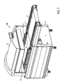
- the Fig. 1 shows a schematic view of a chamber belt machine 100 with a conveyor belt 1, a frame 2, a laying area 3, a chamber 4 and a lid 5.
- the chamber 4 is formed by the lid 5 together with a lower part 12, wherein the lid 5, for example by motor operated automatically opens or manually open, for example, to be evacuated or sealed bag 13th (please refer Fig. 2 ), which are automatically fed by the conveyor belt 1, and which then automatically closes to form the chamber 4.
- the Fig. 2 shows a schematic section of the chamber belt machine 100.
- the lid 5 is provided with a driver 6, which is provided at the bottom of the lid 5 and extends substantially as a square profile into the plane or out of her over the entire length of the chamber 4 ,
- the lid 5 forms with the lower part 12, the chamber 4.
- the bag 13 is provided, in which a product 14 is located.
- the bag 13 has a bag neck 15 which extends in the chamber 4 in the direction of the driver 6.
- a sealing device 7 and a cutting device 8 are provided, which extend in the region of the bag neck 15 in the chamber 4 inside.
- the sealing device 7 and the cutting device 8 cooperate with an abutment 11, which is provided on the lower part 12 and extends over the entire length of the chamber 4 in the drawing plane in and out of her.
- the blow-off assembly 45 according to the invention is shown schematically. The abutment 11 and the blow-off assembly 45 according to the invention will be described later, in particular with reference to FIG FIGS. 4 and 5 , described in more detail.
- the sealing device 7 and the cutting device 8 can be lowered together or independently of each other.
- a trigger 10 is provided in addition to the lower part 12, which is designed as a suction duct and extending over the entire length of the chamber 4 in the drawing plane and out of her.
- the top of the trigger 10 is located substantially at the level of the top of the base 12.
- a gap 16 in the front view of the chamber belt machine is in the upper right area of the trigger 10, a gap 16 (see Fig. 7d - 7i ), which is closed by the lower surface of the driver 6 when the lid 5 is lowered or closed.
- the gap 16 is closed by a protective frame 9 which extends substantially into the plane of the drawing or out of it over the entire length of the chamber 4.
- the protective frame 9 has in the Fig. 2 the shape of a staircase from bottom left to top right.
- a first guard plate 91 is disposed substantially parallel to the ground and partially closes the gap 16 (see FIG Fig. 7d - 7i ).
- a second guard plate 92 joins thereto and extends upwardly substantially orthogonal to the ground.
- a third protective frame plate 93 extends at the top End of the second protective frame plate 92 substantially parallel to the ground to the right.
- the first protective frame plate 91 is located at the lowered lid 5 at the same level as the lower surface and the lower edge of the driver. 6
- a compressed air device 17 is provided. This is optionally provided to provide compressed air for removing the cut-off bag necks 15, in addition to the compressed air flow generated by the blow-off assembly 45, as will be described later.
- a suction device 18 by means of a solid arrow in the trigger 10 shown. Through this, the separated bag necks 15 can be sucked into the trigger and removed along the trigger 10.
- holes 19 are provided on the front of the trigger, so-called failed air holes whose function will be described in more detail below.
- the holes 19 are not limited to the shape shown, but rather a single bore 19 or more holes or openings may be provided of any shape.
- the provision of the compressed air device 17, the suction device 18 and the holes 19 is not absolutely necessary.
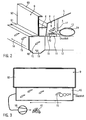
- the Fig. 3 shows a schematic front view of the device according to the Fig. 2 , According to the Fig. 3 the suction device 18 is arranged outside of the trigger 10. The bag necks 15 are in the Fig. 3 sucked out of the trigger 10 in the direction of the solid arrow of the suction device 18.
- a blow-off device which is functionally connected to the trigger 10, in order to blow the bag necks 15 out of the trigger 10 with the aid of compressed air. Through the holes 19 it comes even without a blow-off, but only through the suction device 18 to form an air flow through the trigger 10th
- the abutment 11 comprises a counter-pressure plate 20, on which, as will be explained later, a sealing and a cutting process take place in order to close the bag 13 and separate the bag neck 15.
- the blow-off assembly 45 includes a housing 46 having a surface 47 from which a blow-off element 22 protrudes.
- the blow-off element 22 comprises a blow-off strip 23 arranged over the entire width of the blow-off assembly 45.
- the blow-off strip 23 comprises equidistantly spaced air openings 24 through which compressed air can be flowed from the blow-off strip 23.
- Attached to the blow-off assembly 45 is a ramp section 25 which is primarily bolted to the housing 46.
- the Fig. 4 also shows a Abblasw 23 'with an air opening 24'.
- the blow-off assembly 45 may comprise at least one, but primarily a group of blow-off pins 23 '.
- the Abblasw 23 ' is arranged movably in the counter-pressure plate 20. In a group of Abblaswen 23 'they can be equidistant over the width of the Abblasbauè 45 provided.
- the Abblasstatt 23 ' has a rotationally symmetrical shape.
- the Abblasw 23 ' comprises a rotation, not shown, which ensures that this does not twist in a movement between the first and the second position. This makes it possible to maintain a desired orientation of the air opening 24 '.
- the shows Fig. 4 a cap 49, which is laterally releasably attached to the housing 46.
- an operator can remove the blow-off strip 23 from the guide portion 29 of the housing 46, for example, for cleaning.
- the cap 49 may be provided on both sides of the housing 46.
- the Fig. 5 shows the Abblasbauè 45 according to the invention in section A - A according to the Fig. 4 ,
- the blow-off strip 23 is in a first position in which it is sunk in the housing 46 in such a way that it is flush with the surface 47 of the housing 46.
- the ramp section 25 is arranged, which ensures that the separated bag necks 15 can be well removed from the Abblasbauè and the abutment 11 and not behind it on the lower part 12 of the packaging device according to the Fig. 2 to lie down.
- the counter-pressure plate 20 of Fig. 5 includes a surface 21, and further includes a cutting opening 26 and a sealing member 27 disposed adjacent thereto.
- the cutting apparatus 8 shown in Figure 2 moves into the cutting opening 26 to receive the excess bag neck 15 separate.
- the in the FIG. 2 Sealing device shown from above on the sealing element 27 On the sealing member 27 is a band 28, preferably a Teflon tape arranged. By the band 28, it is possible to prevent the packaging material from sticking to the abutment 11 by the sealing.
- the blow-off strip 23 is arranged in a guide section 29 of the housing 46.
- the counter-pressure plate housing 46 includes a compressed air port 30 through which compressed air in the guide portion 29 can be fed.
- a first and a second stopper 31, 32 are formed to hold the blow-off strip 23 in the guide portion 29 when they are between the first and a second position (see Fig. 6 ) emotional.
- the blow-off strip 23 comprises a vertically oriented leg 33 with a channel 34 formed therein.
- an inlet 41 is also provided which leads into the channel 34.
- From the vertical leg 33 extends laterally a flange 35 which in the Fig. 5 is shown in section.
- the vertical leg 33 with the channel 34 and the flange 35 extending from the vertical leg 33 can be produced, for example, by a bending process.
- a sealing member 37 is arranged as a round cord seal, which seen from the plan view extends around on the flange 35 so that it seals the guide portion 29 when the blow-off 23 is in the second position, in which the flange 35 upwards against the first and second stops 31, 32 presses.
- the sealing element 37 prevents compressed air from the housing 46 penetrates. In addition, it can be prevented that there is an abrupt, loud shock when the blow-off 23 from the in the Fig. 5 shown first position in the in the Fig. 6 shown second position moves.
- An upper portion of the vertical leg 33 is disposed in an opening 39 of the housing 46.
- the vertical leg 33 of the blow-off strip 23 can through the opening 39 of the in Fig. 5 shown position in the position described below Fig. 6 method.
- FIG. 5 a sectional view through the in the Fig. 4 as an alternative to the blow-off 23 shown Abblasw 23 'be. If a plurality of Abblaswe 23 'are provided, they can move synchronously through the opening 39 of the housing 46 between the first and the subsequently explained second position. In this case, for each of the Abblaslixe 23 'each have a cylindrical opening 39 formed in the housing 46.
- the Fig. 6 shows the sectional view A - A of Fig. 4 , wherein the blow-off strip 23, or the Abblasbuild 23 ', is located in the aforementioned second position in which the vertical leg 33 projects beyond the surface 47 of the housing 46.
- the blow-off strip 23 In this position of the blow-off strip 23 is located in the guide section and in the channel 34 of the blow-off 23 compressed air, which is shown dotted. The compressed air was introduced through the pressure port 30 in the guide portion 29 and from there through the inlet 41 into the channel 34.
- blow-off assembly 45 The operation of the blow-off assembly 45 according to the invention will now be described.
- Fig. 7a) - 7j show how the blow-off assembly 45 according to the invention can be used. It is on the device according to the FIG. 2 Referenced.
- the lid 5 is in a lowered position.
- the chamber 4 is evacuated in this step (dashed arrow).
- Blow-off strip 23 is in the first position in which it is sunk in the housing 46.
- the sealing device 7 and the cutting device 8 are lowered and cooperate with the abutment 11.
- the bag 13 is sealed and cut in the product-remote area of the bag neck 15. Also during this step, the blow-off strip 23 is sunk in the housing 46.
- the severed bag neck 15 rests on the blow-off assembly 45.
- the chamber 4 is vented (dashed arrow) and sealed in the bag 13 product 14 is ready for removal.
- the schematically shown blow-off strip 23 is still in the first position, in which it is sunk in the housing 46.
- the cover 5 is raised together with the driver 6 and the sealing device 7 and the cutting device 8.
- the gap 16 opens and has a first opening width. From a predetermined opening width of the gap 16, the blow-off assembly 45 according to the invention is acted upon by compressed air, so that the blow-off strip 23 moves to the second position, in which it protrudes from the housing 46.
- the compressed air which for retracting the blow-off 23 from the in the Fig. 7c shown first position in the in the Fig. 7d shown second position, passes through the inlet 41 into the channel 34 and flows out of the air openings 24 (see FIG. 6 ) to convey the separated bag neck 15 through the opened gap 16 in the trigger 10.
- Fig. 7e is the lid 5 in a first raised position, in which the upper surface of the driver 6 in contact with the inner surface of the third protective frame plate 93 (see Fig. 2 ) of the protective frame 9, the first protective frame plate 91 (see Fig. 2 ) but still in contact with the upper surface of the trigger 10 and closes a part of the gap 16.
- the bag necks 15 are further blown by the compressed air flowing from the air openings 24 in the trigger 10, wherein they bounce partially from the second protective frame plate 92 in the trigger 10.
- the lid 5 is further raised and the protective frame 9 is by the positive connection between the driver 6 and the third protective frame plate 93 (see Fig. 2 ) also raised with.
- the gap 16 increases to a second opening width in which it is completely open.
- Larger or longer bag necks 15 can now also be blown through the gap 16 into the trigger 10 by means of the compressed air flowing out of the abutment 11. So that the bag necks 15 not blown over the gap despite lifting the frame 9 Be, a wall 40 is provided on the trigger 10 as impact protection. From this, the bag necks 15 can be derived in the trigger 10. Long bag necks 15 are usually prior to the enlargement of the gap 16 beyond this or stand on the protective frame 9 at.
- the lid 5 has reached its uppermost position, wherein the trigger 10 or the gap 16 is completely opened. Large bag necks 15 can fall due to gravity and the suction effect described above in the trigger 10 and then be transported away. By switching off the compressed air, the blow-off strip 23 returns to the first position.
- Fig. 7i closes the lid 5 again and the protective frame 9 and the first protective frame plate 91 (see Fig. 2 ) closes a part of the gap 16.
- the gap 16 has again its first opening width.
- the separated bag necks 15, which are located in the trigger 10, are sucked away or blown away supported by compressed air.
- the blow-off assembly 45 according to the invention can be used in different packaging devices and is not limited to the previously described chamber belt machine.
- the Abblasbauè 45 can also be integrated advantageously without great effort in an abutment of a sealing device.
Claims (16)
- Groupe de soufflage (45) pour une unité de scellage (7) d'un dispositif d'emballage (100), comprenant un carter (46) et au moins un élément de soufflage (22), qui peut être déplacé par rapport au carter (46), entre une première position dans laquelle il est au moins partiellement escamoté dans le carter (46), et une deuxième position dans laquelle il fait saillie au moins partiellement à l'extérieur d'une surface extérieure (47) du carter (46).
- Groupe de soufflage selon la revendication 1, caractérisé en ce que l'élément de soufflage (22) comprend une barre de soufflage (23) ou au moins un stylet de soufflage (23').
- Groupe de soufflage selon la revendication 1 ou la revendication 2, caractérisé en ce que l'élément de soufflage (22) est agencé de manière à arriver au ras de la surface extérieure (47) du carter (46) lorsqu'il se trouve dans la première position.
- Groupe de soufflage selon l'une des revendications précédentes, caractérisé en ce que l'élément de soufflage (22) peut coulisser de manière orthogonale à la surface extérieure (47) du carter (46).
- Groupe de soufflage selon l'une des revendications précédentes, caractérisé en ce que dans le carter (46) est formé un tronçon de guidage (29) dans lequel est agencé de manière déplaçable, l'élément de soufflage (22).
- Groupe de soufflage selon la revendication 5, caractérisé en ce que le carter (46) comporte un raccordement de branchement d'air comprimé (30), par l'intermédiaire duquel de l'air comprimé peut être envoyé dans le tronçon de guidage (29).
- Groupe de soufflage selon la revendication 5 ou la revendication 6, caractérisé en ce que le tronçon de guidage (29) présente une ouverture (39) à travers laquelle fait saillie l'élément de soufflage (22) lorsqu'il se trouve dans la deuxième position.
- Groupe de soufflage selon l'une des revendications précédentes, caractérisé en ce que le carter (46) comprend au moins une butée (32, 33), qui maintient l'élément de soufflage (22) contre le carter (46), lorsque l'élément de soufflage (22) se trouve dans la deuxième position.
- Groupe de soufflage selon l'une des revendications précédentes, caractérisé en ce que l'élément de soufflage (22) présente une entrée (41) à travers laquelle de l'air peut être envoyé dans un canal (34) prévu dans l'élément de soufflage (22).
- Groupe de soufflage selon la revendication 9, caractérisé en ce qu'un côté inférieur de l'élément de soufflage (22) présente une surface plus grande que l'entrée (41).
- Groupe de soufflage selon l'une des revendications précédentes, caractérisé en ce que l'élément de soufflage (22) comporte des ouvertures d'air (24) à travers lesquelles peut s'écouler de l'air hors de l'élément de soufflage (22).
- Groupe de soufflage selon l'une des revendications précédentes, caractérisé en ce que l'élément de soufflage (22) présente au moins un élément d'étanchéité (37) pour empêcher un choc abrupt de l'élément de soufflage (22) contre le carter (46).
- Sommier d'appui (11) pour une unité de scellage (7) d'un dispositif d'emballage (100), comprenant un groupe de soufflage (45) selon l'une des revendications précédentes, le carter (46) du groupe de soufflage (45) étant réalisé de manière intégrale avec une plaque de pression conjuguée (20) du sommier d'appui (11).
- Procédé pour éliminer du matériau d'emballage (15) en excédent par un groupe de soufflage (45), qui peut être mis en oeuvre pour une unité de scellage (7) prévue dans un dispositif d'emballage (100), et comporte un carter (46) dans lequel est agencé de manière déplaçable un élément de soufflage (22), procédé d'après lequel on alimente l'élément de soufflage (22) en air comprimé, pour le déplacer par rapport au carter (46), d'une première position dans laquelle il est au moins partiellement escamoté dans le carter (46), à une deuxième position dans laquelle il fait saillie au moins partiellement à l'extérieur d'une surface extérieure (47) du carter (46), de sorte qu'il soulève le matériau d'emballage (15) en excédent,
et d'après lequel l'air comprimé s'écoule au moins en partie hors d'ouvertures d'air (24) prévues dans l'élément de soufflage (22), en vue d'évacuer par soufflage, le matériau d'emballage (15) en excédent, du groupe de soufflage (45). - Procédé selon la revendication 14, caractérisé en ce que l'on alimente l'élément de soufflage (22) en air comprimé, pendant ou après qu'un couvercle (5) du dispositif d'emballage (100) se déplace d'une position fermée à une position ouverte, pour ouvrir partiellement une fente (16) d'un évacuateur (10).
- Procédé selon la revendication 15, caractérisé en ce que l'élément de soufflage (22) est alimenté en air comprimé, tout au plus jusqu'à un instant où le couvercle (5) vient en prise avec un cadre (9) du dispositif d'emballage (100), pour soulever celui-ci, en produisant ainsi l'ouverture complète de la fente (16).
Priority Applications (3)
| Application Number | Priority Date | Filing Date | Title |
|---|---|---|---|
| EP12003000.2A EP2657005B1 (fr) | 2012-04-27 | 2012-04-27 | Groupe de soufflage pour une unité d'étanchéité d'un appareil d'emballage |
| US13/870,894 US9403195B2 (en) | 2012-04-27 | 2013-04-25 | Blowing assembly for a sealing unit of a packaging device |
| CN201310156272.6A CN103373499B (zh) | 2012-04-27 | 2013-04-28 | 包装设备的密封单元用的吹气组件 |
Applications Claiming Priority (1)
| Application Number | Priority Date | Filing Date | Title |
|---|---|---|---|
| EP12003000.2A EP2657005B1 (fr) | 2012-04-27 | 2012-04-27 | Groupe de soufflage pour une unité d'étanchéité d'un appareil d'emballage |
Publications (2)
| Publication Number | Publication Date |
|---|---|
| EP2657005A1 EP2657005A1 (fr) | 2013-10-30 |
| EP2657005B1 true EP2657005B1 (fr) | 2014-06-25 |
Family
ID=46149106
Family Applications (1)
| Application Number | Title | Priority Date | Filing Date |
|---|---|---|---|
| EP12003000.2A Active EP2657005B1 (fr) | 2012-04-27 | 2012-04-27 | Groupe de soufflage pour une unité d'étanchéité d'un appareil d'emballage |
Country Status (3)
| Country | Link |
|---|---|
| US (1) | US9403195B2 (fr) |
| EP (1) | EP2657005B1 (fr) |
| CN (1) | CN103373499B (fr) |
Families Citing this family (7)
| Publication number | Priority date | Publication date | Assignee | Title |
|---|---|---|---|---|
| DE102015010432B4 (de) * | 2015-08-11 | 2021-02-04 | Michatek, K.S. | Schweißbalken für Vakuumschublade sowie Vakuumschublade |
| CN108602572B (zh) * | 2015-09-25 | 2021-09-21 | 克里奥瓦克公司 | 用于将包装抽成真空并密封的设备和方法 |
| IT201600129946A1 (it) * | 2016-12-22 | 2018-06-22 | Altopack Spa | Macchina per il confezionamento di sacchetti per alimenti. |
| IT201600129875A1 (it) * | 2016-12-22 | 2018-06-22 | Altopack Spa | Apparato di saldatura e taglio per testa di sacchetti per alimenti. |
| US11097695B2 (en) * | 2018-10-30 | 2021-08-24 | Waymo Llc | Non-contact cleaning system |
| ES1247635Y (es) * | 2020-04-16 | 2020-09-01 | Coalza Systems S L | Maquina carrusel para confeccionar bolsas paquete |
| DE102021111010B4 (de) * | 2021-04-29 | 2023-03-30 | Multivac Sepp Haggenmüller Se & Co. Kg | Siegelmaschine zum Versiegeln von Verpackungen |
Family Cites Families (9)
| Publication number | Priority date | Publication date | Assignee | Title |
|---|---|---|---|---|
| US3699742A (en) * | 1971-02-18 | 1972-10-24 | Grace W R & Co | Apparatus for vacuum welding of plastics envelopes |
| CH686129A5 (de) * | 1992-10-21 | 1996-01-15 | Luwa Ag Zellweger | Aufsteckvorrichtung fur Garnspulen. |
| JP2585190B2 (ja) | 1994-01-27 | 1997-02-26 | 株式会社島精機製作所 | 裁断機への生地被覆シート供給装置および方法 |
| CN2281313Y (zh) * | 1997-02-03 | 1998-05-13 | 杭州市中亚包装有限公司 | 铝复合膜盖的空气分道装置 |
| CN100443372C (zh) | 2006-04-26 | 2008-12-17 | 长沙楚天科技有限公司 | 自动装药机 |
| DE102008015691B3 (de) | 2008-03-26 | 2010-04-15 | Multivac Sepp Haggenmüller Gmbh & Co. Kg | Vorrichtung und Verfahren zum Verpacken von Produkten in Beuteln |
| CN101734417B (zh) * | 2008-11-13 | 2012-12-26 | 西奎斯特盖有限责任合作公司 | 刺穿衬板的可扭弯的封闭件 |
| CN101439326A (zh) * | 2008-11-25 | 2009-05-27 | 湖南大学 | 一种凝汽器智能移动清洗机器人的高压喷水装置 |
| FI122900B (fi) * | 2010-06-15 | 2012-08-31 | Metso Paper Inc | Kuljetin päänvientinauhan kuljettamiseksi kuiturainakoneessa |
-
2012
- 2012-04-27 EP EP12003000.2A patent/EP2657005B1/fr active Active
-
2013
- 2013-04-25 US US13/870,894 patent/US9403195B2/en active Active
- 2013-04-28 CN CN201310156272.6A patent/CN103373499B/zh active Active
Also Published As
| Publication number | Publication date |
|---|---|
| EP2657005A1 (fr) | 2013-10-30 |
| CN103373499A (zh) | 2013-10-30 |
| CN103373499B (zh) | 2015-06-24 |
| US20130284214A1 (en) | 2013-10-31 |
| US9403195B2 (en) | 2016-08-02 |
Similar Documents
| Publication | Publication Date | Title |
|---|---|---|
| EP2657005B1 (fr) | Groupe de soufflage pour une unité d'étanchéité d'un appareil d'emballage | |
| DE2137058A1 (fr) | ||
| EP3422494A1 (fr) | Dispositif de déconnexion et procédé de déconnexion d'un passe-câble d'un câble | |
| WO2013102682A1 (fr) | Machine d'emballage avec poste de découpe | |
| EP2892706B1 (fr) | Dispositif pour aspirer des produits de rebut d'une machine de production comportant un élément d'aspiration | |
| DE102008015691B3 (de) | Vorrichtung und Verfahren zum Verpacken von Produkten in Beuteln | |
| DE102004032826B4 (de) | Verfahren zum Herstellen von Stanzteilen | |
| DE102012217684B4 (de) | Beschneidstation | |
| DE1783018C3 (de) | Anlage zum mechanischen Entfernen von Anodenblöcken von den Anodenhalterungen mit anschließender Verkleinerung der Anodenreste | |
| DE102013208307B4 (de) | Plattenaufteilanlage | |
| DE202014101589U1 (de) | Verpackungsmaschine | |
| EP3566985B1 (fr) | Dispositif d'empilement de plateaux pourvu d'un moyen de décharge | |
| EP2810880A1 (fr) | Dispositif d'ouverture pour l'ouverture d'une section de sac d'une bande de feuille dans une installation d'ensachage | |
| EP3539883B1 (fr) | Machine d'emballage par emboutissage à renversement de feuille | |
| DE102005062713A1 (de) | Vorrichtung zum Separieren, insbesondere Abfördern eines Teilstapels mit mindestens einer großformatigen Platte von einem Reststapel mit einer Mehrzahl großformatiger Platten | |
| DE102012021153B4 (de) | Kanalballenpresse mit optimiertem Ausweichraum | |
| EP2776347B1 (fr) | Dispositif d'alimentation pour fermetures de contenant | |
| DE102010050877B4 (de) | Vorrichtung zum Anheben und Entleeren von Behältern mit Schüttgütern, insbesondere von Säcken mit rieselfähigen Produkten | |
| DE19642124A1 (de) | Verfahren und Vorrichtung zum Verhindern von Produktionsstörungen an Falzeinrichtungen | |
| DE102014202467A1 (de) | Vorrichtung zur Herstellung einer Gummimischung | |
| DE202013104379U1 (de) | Dämpfungsstruktur einer Vakuumformungs- Schneidemaschine | |
| DE102021111010B4 (de) | Siegelmaschine zum Versiegeln von Verpackungen | |
| EP2384637B1 (fr) | Dispositif de fermeture d'emballages tubulaires | |
| EP2986102B1 (fr) | Dispositif de prélèvement de fourrage ensilé | |
| DE2610475C3 (de) | Vorrichtung zum einzelweisen Entnehmen und Abführen von Platten |
Legal Events
| Date | Code | Title | Description |
|---|---|---|---|
| PUAI | Public reference made under article 153(3) epc to a published international application that has entered the european phase |
Free format text: ORIGINAL CODE: 0009012 |
|
| AK | Designated contracting states |
Kind code of ref document: A1 Designated state(s): AL AT BE BG CH CY CZ DE DK EE ES FI FR GB GR HR HU IE IS IT LI LT LU LV MC MK MT NL NO PL PT RO RS SE SI SK SM TR |
|
| AX | Request for extension of the european patent |
Extension state: BA ME |
|
| 17P | Request for examination filed |
Effective date: 20131122 |
|
| RBV | Designated contracting states (corrected) |
Designated state(s): AL AT BE BG CH CY CZ DE DK EE ES FI FR GB GR HR HU IE IS IT LI LT LU LV MC MK MT NL NO PL PT RO RS SE SI SK SM TR |
|
| RIC1 | Information provided on ipc code assigned before grant |
Ipc: B08B 5/02 20060101ALI20131211BHEP Ipc: B29C 65/00 20060101AFI20131211BHEP Ipc: B65B 51/14 20060101ALI20131211BHEP Ipc: B65B 51/10 20060101ALI20131211BHEP |
|
| GRAP | Despatch of communication of intention to grant a patent |
Free format text: ORIGINAL CODE: EPIDOSNIGR1 |
|
| INTG | Intention to grant announced |
Effective date: 20140122 |
|
| GRAS | Grant fee paid |
Free format text: ORIGINAL CODE: EPIDOSNIGR3 |
|
| GRAA | (expected) grant |
Free format text: ORIGINAL CODE: 0009210 |
|
| AK | Designated contracting states |
Kind code of ref document: B1 Designated state(s): AL AT BE BG CH CY CZ DE DK EE ES FI FR GB GR HR HU IE IS IT LI LT LU LV MC MK MT NL NO PL PT RO RS SE SI SK SM TR |
|
| REG | Reference to a national code |
Ref country code: GB Ref legal event code: FG4D Free format text: NOT ENGLISH |
|
| REG | Reference to a national code |
Ref country code: CH Ref legal event code: EP Ref country code: CH Ref legal event code: NV Representative=s name: BOVARD AG, CH |
|
| REG | Reference to a national code |
Ref country code: AT Ref legal event code: REF Ref document number: 674357 Country of ref document: AT Kind code of ref document: T Effective date: 20140715 |
|
| REG | Reference to a national code |
Ref country code: IE Ref legal event code: FG4D Free format text: LANGUAGE OF EP DOCUMENT: GERMAN |
|
| REG | Reference to a national code |
Ref country code: DE Ref legal event code: R096 Ref document number: 502012000908 Country of ref document: DE Effective date: 20140814 |
|
| PG25 | Lapsed in a contracting state [announced via postgrant information from national office to epo] |
Ref country code: NO Free format text: LAPSE BECAUSE OF FAILURE TO SUBMIT A TRANSLATION OF THE DESCRIPTION OR TO PAY THE FEE WITHIN THE PRESCRIBED TIME-LIMIT Effective date: 20140925 Ref country code: CY Free format text: LAPSE BECAUSE OF FAILURE TO SUBMIT A TRANSLATION OF THE DESCRIPTION OR TO PAY THE FEE WITHIN THE PRESCRIBED TIME-LIMIT Effective date: 20140625 Ref country code: FI Free format text: LAPSE BECAUSE OF FAILURE TO SUBMIT A TRANSLATION OF THE DESCRIPTION OR TO PAY THE FEE WITHIN THE PRESCRIBED TIME-LIMIT Effective date: 20140625 Ref country code: GR Free format text: LAPSE BECAUSE OF FAILURE TO SUBMIT A TRANSLATION OF THE DESCRIPTION OR TO PAY THE FEE WITHIN THE PRESCRIBED TIME-LIMIT Effective date: 20140926 Ref country code: LT Free format text: LAPSE BECAUSE OF FAILURE TO SUBMIT A TRANSLATION OF THE DESCRIPTION OR TO PAY THE FEE WITHIN THE PRESCRIBED TIME-LIMIT Effective date: 20140625 |
|
| REG | Reference to a national code |
Ref country code: NL Ref legal event code: VDEP Effective date: 20140625 |
|
| REG | Reference to a national code |
Ref country code: LT Ref legal event code: MG4D |
|
| PG25 | Lapsed in a contracting state [announced via postgrant information from national office to epo] |
Ref country code: LV Free format text: LAPSE BECAUSE OF FAILURE TO SUBMIT A TRANSLATION OF THE DESCRIPTION OR TO PAY THE FEE WITHIN THE PRESCRIBED TIME-LIMIT Effective date: 20140625 Ref country code: HR Free format text: LAPSE BECAUSE OF FAILURE TO SUBMIT A TRANSLATION OF THE DESCRIPTION OR TO PAY THE FEE WITHIN THE PRESCRIBED TIME-LIMIT Effective date: 20140625 Ref country code: RS Free format text: LAPSE BECAUSE OF FAILURE TO SUBMIT A TRANSLATION OF THE DESCRIPTION OR TO PAY THE FEE WITHIN THE PRESCRIBED TIME-LIMIT Effective date: 20140625 Ref country code: SE Free format text: LAPSE BECAUSE OF FAILURE TO SUBMIT A TRANSLATION OF THE DESCRIPTION OR TO PAY THE FEE WITHIN THE PRESCRIBED TIME-LIMIT Effective date: 20140625 |
|
| PG25 | Lapsed in a contracting state [announced via postgrant information from national office to epo] |
Ref country code: CZ Free format text: LAPSE BECAUSE OF FAILURE TO SUBMIT A TRANSLATION OF THE DESCRIPTION OR TO PAY THE FEE WITHIN THE PRESCRIBED TIME-LIMIT Effective date: 20140625 Ref country code: SK Free format text: LAPSE BECAUSE OF FAILURE TO SUBMIT A TRANSLATION OF THE DESCRIPTION OR TO PAY THE FEE WITHIN THE PRESCRIBED TIME-LIMIT Effective date: 20140625 Ref country code: ES Free format text: LAPSE BECAUSE OF FAILURE TO SUBMIT A TRANSLATION OF THE DESCRIPTION OR TO PAY THE FEE WITHIN THE PRESCRIBED TIME-LIMIT Effective date: 20140625 Ref country code: PT Free format text: LAPSE BECAUSE OF FAILURE TO SUBMIT A TRANSLATION OF THE DESCRIPTION OR TO PAY THE FEE WITHIN THE PRESCRIBED TIME-LIMIT Effective date: 20141027 Ref country code: EE Free format text: LAPSE BECAUSE OF FAILURE TO SUBMIT A TRANSLATION OF THE DESCRIPTION OR TO PAY THE FEE WITHIN THE PRESCRIBED TIME-LIMIT Effective date: 20140625 Ref country code: RO Free format text: LAPSE BECAUSE OF FAILURE TO SUBMIT A TRANSLATION OF THE DESCRIPTION OR TO PAY THE FEE WITHIN THE PRESCRIBED TIME-LIMIT Effective date: 20140625 |
|
| PG25 | Lapsed in a contracting state [announced via postgrant information from national office to epo] |
Ref country code: NL Free format text: LAPSE BECAUSE OF FAILURE TO SUBMIT A TRANSLATION OF THE DESCRIPTION OR TO PAY THE FEE WITHIN THE PRESCRIBED TIME-LIMIT Effective date: 20140625 Ref country code: IS Free format text: LAPSE BECAUSE OF FAILURE TO SUBMIT A TRANSLATION OF THE DESCRIPTION OR TO PAY THE FEE WITHIN THE PRESCRIBED TIME-LIMIT Effective date: 20141025 Ref country code: PL Free format text: LAPSE BECAUSE OF FAILURE TO SUBMIT A TRANSLATION OF THE DESCRIPTION OR TO PAY THE FEE WITHIN THE PRESCRIBED TIME-LIMIT Effective date: 20140625 |
|
| REG | Reference to a national code |
Ref country code: DE Ref legal event code: R097 Ref document number: 502012000908 Country of ref document: DE |
|
| PG25 | Lapsed in a contracting state [announced via postgrant information from national office to epo] |
Ref country code: DK Free format text: LAPSE BECAUSE OF FAILURE TO SUBMIT A TRANSLATION OF THE DESCRIPTION OR TO PAY THE FEE WITHIN THE PRESCRIBED TIME-LIMIT Effective date: 20140625 |
|
| PLBE | No opposition filed within time limit |
Free format text: ORIGINAL CODE: 0009261 |
|
| STAA | Information on the status of an ep patent application or granted ep patent |
Free format text: STATUS: NO OPPOSITION FILED WITHIN TIME LIMIT |
|
| 26N | No opposition filed |
Effective date: 20150326 |
|
| PG25 | Lapsed in a contracting state [announced via postgrant information from national office to epo] |
Ref country code: LU Free format text: LAPSE BECAUSE OF FAILURE TO SUBMIT A TRANSLATION OF THE DESCRIPTION OR TO PAY THE FEE WITHIN THE PRESCRIBED TIME-LIMIT Effective date: 20150427 Ref country code: SI Free format text: LAPSE BECAUSE OF FAILURE TO SUBMIT A TRANSLATION OF THE DESCRIPTION OR TO PAY THE FEE WITHIN THE PRESCRIBED TIME-LIMIT Effective date: 20140625 Ref country code: MC Free format text: LAPSE BECAUSE OF FAILURE TO SUBMIT A TRANSLATION OF THE DESCRIPTION OR TO PAY THE FEE WITHIN THE PRESCRIBED TIME-LIMIT Effective date: 20140625 |
|
| REG | Reference to a national code |
Ref country code: IE Ref legal event code: MM4A |
|
| REG | Reference to a national code |
Ref country code: DE Ref legal event code: R082 Ref document number: 502012000908 Country of ref document: DE Representative=s name: GRUENECKER PATENT- UND RECHTSANWAELTE PARTG MB, DE Ref country code: DE Ref legal event code: R081 Ref document number: 502012000908 Country of ref document: DE Owner name: MULTIVAC SEPP HAGGENMUELLER SE & CO. KG, DE Free format text: FORMER OWNER: MULTIVAC SEPP HAGGENMUELLER GMBH & CO. KG, 87787 WOLFERTSCHWENDEN, DE |
|
| REG | Reference to a national code |
Ref country code: FR Ref legal event code: PLFP Year of fee payment: 5 |
|
| PG25 | Lapsed in a contracting state [announced via postgrant information from national office to epo] |
Ref country code: IE Free format text: LAPSE BECAUSE OF NON-PAYMENT OF DUE FEES Effective date: 20150427 |
|
| PG25 | Lapsed in a contracting state [announced via postgrant information from national office to epo] |
Ref country code: MT Free format text: LAPSE BECAUSE OF FAILURE TO SUBMIT A TRANSLATION OF THE DESCRIPTION OR TO PAY THE FEE WITHIN THE PRESCRIBED TIME-LIMIT Effective date: 20140625 |
|
| REG | Reference to a national code |
Ref country code: FR Ref legal event code: PLFP Year of fee payment: 6 |
|
| PG25 | Lapsed in a contracting state [announced via postgrant information from national office to epo] |
Ref country code: SM Free format text: LAPSE BECAUSE OF FAILURE TO SUBMIT A TRANSLATION OF THE DESCRIPTION OR TO PAY THE FEE WITHIN THE PRESCRIBED TIME-LIMIT Effective date: 20140625 Ref country code: BG Free format text: LAPSE BECAUSE OF FAILURE TO SUBMIT A TRANSLATION OF THE DESCRIPTION OR TO PAY THE FEE WITHIN THE PRESCRIBED TIME-LIMIT Effective date: 20140625 Ref country code: HU Free format text: LAPSE BECAUSE OF FAILURE TO SUBMIT A TRANSLATION OF THE DESCRIPTION OR TO PAY THE FEE WITHIN THE PRESCRIBED TIME-LIMIT; INVALID AB INITIO Effective date: 20120427 |
|
| PG25 | Lapsed in a contracting state [announced via postgrant information from national office to epo] |
Ref country code: BE Free format text: LAPSE BECAUSE OF NON-PAYMENT OF DUE FEES Effective date: 20150430 |
|
| REG | Reference to a national code |
Ref country code: FR Ref legal event code: PLFP Year of fee payment: 7 |
|
| PG25 | Lapsed in a contracting state [announced via postgrant information from national office to epo] |
Ref country code: MK Free format text: LAPSE BECAUSE OF FAILURE TO SUBMIT A TRANSLATION OF THE DESCRIPTION OR TO PAY THE FEE WITHIN THE PRESCRIBED TIME-LIMIT Effective date: 20140625 |
|
| PG25 | Lapsed in a contracting state [announced via postgrant information from national office to epo] |
Ref country code: AL Free format text: LAPSE BECAUSE OF FAILURE TO SUBMIT A TRANSLATION OF THE DESCRIPTION OR TO PAY THE FEE WITHIN THE PRESCRIBED TIME-LIMIT Effective date: 20140625 |
|
| P01 | Opt-out of the competence of the unified patent court (upc) registered |
Effective date: 20230404 |
|
| PGFP | Annual fee paid to national office [announced via postgrant information from national office to epo] |
Ref country code: IT Payment date: 20230428 Year of fee payment: 12 Ref country code: FR Payment date: 20230417 Year of fee payment: 12 Ref country code: DE Payment date: 20230418 Year of fee payment: 12 Ref country code: CH Payment date: 20230502 Year of fee payment: 12 |
|
| PGFP | Annual fee paid to national office [announced via postgrant information from national office to epo] |
Ref country code: TR Payment date: 20230426 Year of fee payment: 12 Ref country code: AT Payment date: 20230414 Year of fee payment: 12 |
|
| PGFP | Annual fee paid to national office [announced via postgrant information from national office to epo] |
Ref country code: GB Payment date: 20230420 Year of fee payment: 12 |