EP2656883B1 - Mold and method of molding golf ball core - Google Patents
Mold and method of molding golf ball core Download PDFInfo
- Publication number
- EP2656883B1 EP2656883B1 EP13164661.4A EP13164661A EP2656883B1 EP 2656883 B1 EP2656883 B1 EP 2656883B1 EP 13164661 A EP13164661 A EP 13164661A EP 2656883 B1 EP2656883 B1 EP 2656883B1
- Authority
- EP
- European Patent Office
- Prior art keywords
- mold
- projection
- mold plate
- plate
- movable insert
- Prior art date
- Legal status (The legal status is an assumption and is not a legal conclusion. Google has not performed a legal analysis and makes no representation as to the accuracy of the status listed.)
- Not-in-force
Links
- 238000000465 moulding Methods 0.000 title claims description 59
- 238000000034 method Methods 0.000 title claims description 30
- 239000000463 material Substances 0.000 claims description 48
- 238000004519 manufacturing process Methods 0.000 claims description 15
- 239000011248 coating agent Substances 0.000 claims description 11
- 238000000576 coating method Methods 0.000 claims description 11
- 239000007787 solid Substances 0.000 claims description 3
- 239000011162 core material Substances 0.000 description 151
- 229920001577 copolymer Polymers 0.000 description 16
- 238000000748 compression moulding Methods 0.000 description 12
- 229920000554 ionomer Polymers 0.000 description 10
- 239000000203 mixture Substances 0.000 description 10
- 229920001296 polysiloxane Polymers 0.000 description 10
- 230000006835 compression Effects 0.000 description 9
- 229920000642 polymer Polymers 0.000 description 9
- 238000007906 compression Methods 0.000 description 8
- -1 cover Substances 0.000 description 8
- 238000010276 construction Methods 0.000 description 7
- 229920001971 elastomer Polymers 0.000 description 7
- 239000005062 Polybutadiene Substances 0.000 description 6
- 229920002857 polybutadiene Polymers 0.000 description 6
- 239000005060 rubber Substances 0.000 description 5
- 229920001187 thermosetting polymer Polymers 0.000 description 5
- 239000004711 α-olefin Substances 0.000 description 5
- LIKMAJRDDDTEIG-UHFFFAOYSA-N 1-hexene Chemical compound CCCCC=C LIKMAJRDDDTEIG-UHFFFAOYSA-N 0.000 description 4
- 241000237858 Gastropoda Species 0.000 description 4
- OFOBLEOULBTSOW-UHFFFAOYSA-N Malonic acid Chemical compound OC(=O)CC(O)=O OFOBLEOULBTSOW-UHFFFAOYSA-N 0.000 description 4
- 239000004952 Polyamide Substances 0.000 description 4
- 239000002253 acid Substances 0.000 description 4
- 125000003342 alkenyl group Chemical group 0.000 description 4
- 125000004432 carbon atom Chemical group C* 0.000 description 4
- 229920002647 polyamide Polymers 0.000 description 4
- 229920005989 resin Polymers 0.000 description 4
- 239000011347 resin Substances 0.000 description 4
- VZCYOOQTPOCHFL-UHFFFAOYSA-N trans-butenedioic acid Natural products OC(=O)C=CC(O)=O VZCYOOQTPOCHFL-UHFFFAOYSA-N 0.000 description 4
- 229920002943 EPDM rubber Polymers 0.000 description 3
- 239000004593 Epoxy Substances 0.000 description 3
- MUBZPKHOEPUJKR-UHFFFAOYSA-N Oxalic acid Chemical compound OC(=O)C(O)=O MUBZPKHOEPUJKR-UHFFFAOYSA-N 0.000 description 3
- 230000000994 depressogenic effect Effects 0.000 description 3
- 238000001746 injection moulding Methods 0.000 description 3
- 229920001200 poly(ethylene-vinyl acetate) Polymers 0.000 description 3
- 229920001897 terpolymer Polymers 0.000 description 3
- PBLZLIFKVPJDCO-UHFFFAOYSA-N 12-aminododecanoic acid Chemical compound NCCCCCCCCCCCC(O)=O PBLZLIFKVPJDCO-UHFFFAOYSA-N 0.000 description 2
- SMZOUWXMTYCWNB-UHFFFAOYSA-N 2-(2-methoxy-5-methylphenyl)ethanamine Chemical compound COC1=CC=C(C)C=C1CCN SMZOUWXMTYCWNB-UHFFFAOYSA-N 0.000 description 2
- JAHNSTQSQJOJLO-UHFFFAOYSA-N 2-(3-fluorophenyl)-1h-imidazole Chemical compound FC1=CC=CC(C=2NC=CN=2)=C1 JAHNSTQSQJOJLO-UHFFFAOYSA-N 0.000 description 2
- SZTBMYHIYNGYIA-UHFFFAOYSA-N 2-chloroacrylic acid Chemical compound OC(=O)C(Cl)=C SZTBMYHIYNGYIA-UHFFFAOYSA-N 0.000 description 2
- WROUWQQRXUBECT-UHFFFAOYSA-N 2-ethylacrylic acid Chemical compound CCC(=C)C(O)=O WROUWQQRXUBECT-UHFFFAOYSA-N 0.000 description 2
- QISOBCMNUJQOJU-UHFFFAOYSA-N 4-bromo-1h-pyrazole-5-carboxylic acid Chemical compound OC(=O)C=1NN=CC=1Br QISOBCMNUJQOJU-UHFFFAOYSA-N 0.000 description 2
- VZCYOOQTPOCHFL-OWOJBTEDSA-N Fumaric acid Natural products OC(=O)\C=C\C(O)=O VZCYOOQTPOCHFL-OWOJBTEDSA-N 0.000 description 2
- 229920002633 Kraton (polymer) Polymers 0.000 description 2
- JHWNWJKBPDFINM-UHFFFAOYSA-N Laurolactam Chemical compound O=C1CCCCCCCCCCCN1 JHWNWJKBPDFINM-UHFFFAOYSA-N 0.000 description 2
- 229920000106 Liquid crystal polymer Polymers 0.000 description 2
- 239000004977 Liquid-crystal polymers (LCPs) Substances 0.000 description 2
- CERQOIWHTDAKMF-UHFFFAOYSA-N Methacrylic acid Chemical compound CC(=C)C(O)=O CERQOIWHTDAKMF-UHFFFAOYSA-N 0.000 description 2
- BAPJBEWLBFYGME-UHFFFAOYSA-N Methyl acrylate Chemical compound COC(=O)C=C BAPJBEWLBFYGME-UHFFFAOYSA-N 0.000 description 2
- 229920002396 Polyurea Polymers 0.000 description 2
- KKEYFWRCBNTPAC-UHFFFAOYSA-N Terephthalic acid Chemical compound OC(=O)C1=CC=C(C(O)=O)C=C1 KKEYFWRCBNTPAC-UHFFFAOYSA-N 0.000 description 2
- 238000009825 accumulation Methods 0.000 description 2
- 230000004913 activation Effects 0.000 description 2
- WNLRTRBMVRJNCN-UHFFFAOYSA-N adipic acid Chemical compound OC(=O)CCCCC(O)=O WNLRTRBMVRJNCN-UHFFFAOYSA-N 0.000 description 2
- 125000001931 aliphatic group Chemical group 0.000 description 2
- 125000000217 alkyl group Chemical group 0.000 description 2
- VHRGRCVQAFMJIZ-UHFFFAOYSA-N cadaverine Chemical compound NCCCCCN VHRGRCVQAFMJIZ-UHFFFAOYSA-N 0.000 description 2
- 150000007942 carboxylates Chemical class 0.000 description 2
- 150000001735 carboxylic acids Chemical class 0.000 description 2
- 150000001768 cations Chemical class 0.000 description 2
- 230000000052 comparative effect Effects 0.000 description 2
- LDHQCZJRKDOVOX-NSCUHMNNSA-N crotonic acid Chemical compound C\C=C\C(O)=O LDHQCZJRKDOVOX-NSCUHMNNSA-N 0.000 description 2
- 150000004985 diamines Chemical class 0.000 description 2
- 239000000806 elastomer Substances 0.000 description 2
- JBKVHLHDHHXQEQ-UHFFFAOYSA-N epsilon-caprolactam Chemical compound O=C1CCCCCN1 JBKVHLHDHHXQEQ-UHFFFAOYSA-N 0.000 description 2
- 239000005038 ethylene vinyl acetate Substances 0.000 description 2
- NAQMVNRVTILPCV-UHFFFAOYSA-N hexane-1,6-diamine Chemical compound NCCCCCCN NAQMVNRVTILPCV-UHFFFAOYSA-N 0.000 description 2
- 150000002430 hydrocarbons Chemical group 0.000 description 2
- 238000007373 indentation Methods 0.000 description 2
- QQVIHTHCMHWDBS-UHFFFAOYSA-N isophthalic acid Chemical compound OC(=O)C1=CC=CC(C(O)=O)=C1 QQVIHTHCMHWDBS-UHFFFAOYSA-N 0.000 description 2
- VZCYOOQTPOCHFL-UPHRSURJSA-N maleic acid Chemical compound OC(=O)\C=C/C(O)=O VZCYOOQTPOCHFL-UPHRSURJSA-N 0.000 description 2
- 229910021645 metal ion Inorganic materials 0.000 description 2
- LVHBHZANLOWSRM-UHFFFAOYSA-N methylenebutanedioic acid Natural products OC(=O)CC(=C)C(O)=O LVHBHZANLOWSRM-UHFFFAOYSA-N 0.000 description 2
- 239000012778 molding material Substances 0.000 description 2
- 239000000178 monomer Substances 0.000 description 2
- 238000006386 neutralization reaction Methods 0.000 description 2
- 230000003472 neutralizing effect Effects 0.000 description 2
- 238000006068 polycondensation reaction Methods 0.000 description 2
- 229920000728 polyester Polymers 0.000 description 2
- 229920001195 polyisoprene Polymers 0.000 description 2
- 229920000098 polyolefin Polymers 0.000 description 2
- 229920001955 polyphenylene ether Polymers 0.000 description 2
- 229920002635 polyurethane Polymers 0.000 description 2
- 239000004814 polyurethane Substances 0.000 description 2
- KIDHWZJUCRJVML-UHFFFAOYSA-N putrescine Chemical compound NCCCCN KIDHWZJUCRJVML-UHFFFAOYSA-N 0.000 description 2
- CXMXRPHRNRROMY-UHFFFAOYSA-N sebacic acid Chemical compound OC(=O)CCCCCCCCC(O)=O CXMXRPHRNRROMY-UHFFFAOYSA-N 0.000 description 2
- 239000011343 solid material Substances 0.000 description 2
- 229920006249 styrenic copolymer Polymers 0.000 description 2
- 239000000126 substance Substances 0.000 description 2
- 229920003051 synthetic elastomer Polymers 0.000 description 2
- 239000005061 synthetic rubber Substances 0.000 description 2
- LDHQCZJRKDOVOX-UHFFFAOYSA-N trans-crotonic acid Natural products CC=CC(O)=O LDHQCZJRKDOVOX-UHFFFAOYSA-N 0.000 description 2
- 150000007934 α,β-unsaturated carboxylic acids Chemical class 0.000 description 2
- PXGZQGDTEZPERC-UHFFFAOYSA-N 1,4-cyclohexanedicarboxylic acid Chemical compound OC(=O)C1CCC(C(O)=O)CC1 PXGZQGDTEZPERC-UHFFFAOYSA-N 0.000 description 1
- GUOSQNAUYHMCRU-UHFFFAOYSA-N 11-Aminoundecanoic acid Chemical compound NCCCCCCCCCCC(O)=O GUOSQNAUYHMCRU-UHFFFAOYSA-N 0.000 description 1
- 125000000094 2-phenylethyl group Chemical group [H]C1=C([H])C([H])=C(C([H])=C1[H])C([H])([H])C([H])([H])* 0.000 description 1
- 125000003903 2-propenyl group Chemical group [H]C([*])([H])C([H])=C([H])[H] 0.000 description 1
- PYSRRFNXTXNWCD-UHFFFAOYSA-N 3-(2-phenylethenyl)furan-2,5-dione Chemical compound O=C1OC(=O)C(C=CC=2C=CC=CC=2)=C1 PYSRRFNXTXNWCD-UHFFFAOYSA-N 0.000 description 1
- LIMIJVKKNPAMJE-UHFFFAOYSA-N 5-phenylpenta-2,4-dienenitrile prop-2-enenitrile Chemical compound C=CC#N.N#CC=CC=Cc1ccccc1 LIMIJVKKNPAMJE-UHFFFAOYSA-N 0.000 description 1
- SLXKOJJOQWFEFD-UHFFFAOYSA-N 6-aminohexanoic acid Chemical compound NCCCCCC(O)=O SLXKOJJOQWFEFD-UHFFFAOYSA-N 0.000 description 1
- VWPQCOZMXULHDM-UHFFFAOYSA-N 9-aminononanoic acid Chemical compound NCCCCCCCCC(O)=O VWPQCOZMXULHDM-UHFFFAOYSA-N 0.000 description 1
- BJRMDQLATQGMCQ-UHFFFAOYSA-N C=C.C=CC=C.C=CC1=CC=CC=C1.C=CC1=CC=CC=C1 Chemical compound C=C.C=CC=C.C=CC1=CC=CC=C1.C=CC1=CC=CC=C1 BJRMDQLATQGMCQ-UHFFFAOYSA-N 0.000 description 1
- KXDHJXZQYSOELW-UHFFFAOYSA-N Carbamic acid Chemical compound NC(O)=O KXDHJXZQYSOELW-UHFFFAOYSA-N 0.000 description 1
- 239000004215 Carbon black (E152) Substances 0.000 description 1
- 239000004641 Diallyl-phthalate Substances 0.000 description 1
- JIGUQPWFLRLWPJ-UHFFFAOYSA-N Ethyl acrylate Chemical compound CCOC(=O)C=C JIGUQPWFLRLWPJ-UHFFFAOYSA-N 0.000 description 1
- 229920000181 Ethylene propylene rubber Polymers 0.000 description 1
- PIICEJLVQHRZGT-UHFFFAOYSA-N Ethylenediamine Chemical compound NCCN PIICEJLVQHRZGT-UHFFFAOYSA-N 0.000 description 1
- 244000043261 Hevea brasiliensis Species 0.000 description 1
- 239000004677 Nylon Substances 0.000 description 1
- 229920000571 Nylon 11 Polymers 0.000 description 1
- 229920000299 Nylon 12 Polymers 0.000 description 1
- 229920003189 Nylon 4,6 Polymers 0.000 description 1
- 229920002292 Nylon 6 Polymers 0.000 description 1
- 229920000305 Nylon 6,10 Polymers 0.000 description 1
- 229920002302 Nylon 6,6 Polymers 0.000 description 1
- 229920000007 Nylon MXD6 Polymers 0.000 description 1
- 229920000147 Styrene maleic anhydride Polymers 0.000 description 1
- 229920003182 Surlyn® Polymers 0.000 description 1
- 239000005035 Surlyn® Substances 0.000 description 1
- 229920006362 Teflon® Polymers 0.000 description 1
- 229920004482 WACKER® Polymers 0.000 description 1
- FDLQZKYLHJJBHD-UHFFFAOYSA-N [3-(aminomethyl)phenyl]methanamine Chemical compound NCC1=CC=CC(CN)=C1 FDLQZKYLHJJBHD-UHFFFAOYSA-N 0.000 description 1
- XECAHXYUAAWDEL-UHFFFAOYSA-N acrylonitrile butadiene styrene Chemical compound C=CC=C.C=CC#N.C=CC1=CC=CC=C1 XECAHXYUAAWDEL-UHFFFAOYSA-N 0.000 description 1
- 229920000122 acrylonitrile butadiene styrene Polymers 0.000 description 1
- 239000004676 acrylonitrile butadiene styrene Substances 0.000 description 1
- 235000011037 adipic acid Nutrition 0.000 description 1
- 239000001361 adipic acid Substances 0.000 description 1
- 229960002684 aminocaproic acid Drugs 0.000 description 1
- 238000004873 anchoring Methods 0.000 description 1
- 125000003710 aryl alkyl group Chemical group 0.000 description 1
- 125000003118 aryl group Chemical group 0.000 description 1
- 244000001591 balata Species 0.000 description 1
- 235000016302 balata Nutrition 0.000 description 1
- 125000001797 benzyl group Chemical group [H]C1=C([H])C([H])=C(C([H])=C1[H])C([H])([H])* 0.000 description 1
- 230000015572 biosynthetic process Effects 0.000 description 1
- QUDWYFHPNIMBFC-UHFFFAOYSA-N bis(prop-2-enyl) benzene-1,2-dicarboxylate Chemical compound C=CCOC(=O)C1=CC=CC=C1C(=O)OCC=C QUDWYFHPNIMBFC-UHFFFAOYSA-N 0.000 description 1
- DQXBYHZEEUGOBF-UHFFFAOYSA-N but-3-enoic acid;ethene Chemical compound C=C.OC(=O)CC=C DQXBYHZEEUGOBF-UHFFFAOYSA-N 0.000 description 1
- 125000004369 butenyl group Chemical group C(=CCC)* 0.000 description 1
- CQEYYJKEWSMYFG-UHFFFAOYSA-N butyl acrylate Chemical compound CCCCOC(=O)C=C CQEYYJKEWSMYFG-UHFFFAOYSA-N 0.000 description 1
- 125000000484 butyl group Chemical group [H]C([*])([H])C([H])([H])C([H])([H])C([H])([H])[H] 0.000 description 1
- 229920005549 butyl rubber Polymers 0.000 description 1
- 150000001732 carboxylic acid derivatives Chemical class 0.000 description 1
- 238000005266 casting Methods 0.000 description 1
- 229920002678 cellulose Polymers 0.000 description 1
- 239000001913 cellulose Substances 0.000 description 1
- 125000004218 chloromethyl group Chemical group [H]C([H])(Cl)* 0.000 description 1
- 150000001875 compounds Chemical class 0.000 description 1
- 238000007334 copolymerization reaction Methods 0.000 description 1
- 125000000753 cycloalkyl group Chemical group 0.000 description 1
- 125000000582 cycloheptyl group Chemical group [H]C1([H])C([H])([H])C([H])([H])C([H])([H])C([H])(*)C([H])([H])C1([H])[H] 0.000 description 1
- 125000000113 cyclohexyl group Chemical group [H]C1([H])C([H])([H])C([H])([H])C([H])(*)C([H])([H])C1([H])[H] 0.000 description 1
- YQLZOAVZWJBZSY-UHFFFAOYSA-N decane-1,10-diamine Chemical compound NCCCCCCCCCCN YQLZOAVZWJBZSY-UHFFFAOYSA-N 0.000 description 1
- 125000003493 decenyl group Chemical group [H]C([*])=C([H])C([H])([H])C([H])([H])C([H])([H])C([H])([H])C([H])([H])C([H])([H])C([H])([H])C([H])([H])[H] 0.000 description 1
- 229920000359 diblock copolymer Polymers 0.000 description 1
- 235000013870 dimethyl polysiloxane Nutrition 0.000 description 1
- 230000009977 dual effect Effects 0.000 description 1
- 238000005516 engineering process Methods 0.000 description 1
- 125000003700 epoxy group Chemical group 0.000 description 1
- 125000001495 ethyl group Chemical group [H]C([H])([H])C([H])([H])* 0.000 description 1
- 229920002313 fluoropolymer Polymers 0.000 description 1
- 239000004811 fluoropolymer Substances 0.000 description 1
- 229920005555 halobutyl Polymers 0.000 description 1
- 125000004968 halobutyl group Chemical group 0.000 description 1
- 150000008282 halocarbons Chemical group 0.000 description 1
- 125000006038 hexenyl group Chemical group 0.000 description 1
- 125000004051 hexyl group Chemical group [H]C([H])([H])C([H])([H])C([H])([H])C([H])([H])C([H])([H])C([H])([H])* 0.000 description 1
- 229920005669 high impact polystyrene Polymers 0.000 description 1
- 239000004797 high-impact polystyrene Substances 0.000 description 1
- 229930195733 hydrocarbon Natural products 0.000 description 1
- 125000002496 methyl group Chemical group [H]C([H])([H])* 0.000 description 1
- 238000012986 modification Methods 0.000 description 1
- 230000004048 modification Effects 0.000 description 1
- 229920003052 natural elastomer Polymers 0.000 description 1
- 229920001194 natural rubber Polymers 0.000 description 1
- 229920001778 nylon Polymers 0.000 description 1
- 125000000962 organic group Chemical group 0.000 description 1
- 235000006408 oxalic acid Nutrition 0.000 description 1
- 125000002255 pentenyl group Chemical group C(=CCCC)* 0.000 description 1
- 125000001147 pentyl group Chemical group C(CCCC)* 0.000 description 1
- PNJWIWWMYCMZRO-UHFFFAOYSA-N pent‐4‐en‐2‐one Natural products CC(=O)CC=C PNJWIWWMYCMZRO-UHFFFAOYSA-N 0.000 description 1
- 125000001997 phenyl group Chemical group [H]C1=C([H])C([H])=C(*)C([H])=C1[H] 0.000 description 1
- 229920000435 poly(dimethylsiloxane) Polymers 0.000 description 1
- 229920000058 polyacrylate Polymers 0.000 description 1
- 229920001230 polyarylate Polymers 0.000 description 1
- 229920000515 polycarbonate Polymers 0.000 description 1
- 239000004417 polycarbonate Substances 0.000 description 1
- 229920000346 polystyrene-polyisoprene block-polystyrene Polymers 0.000 description 1
- 229920002451 polyvinyl alcohol Polymers 0.000 description 1
- 235000019422 polyvinyl alcohol Nutrition 0.000 description 1
- 238000003825 pressing Methods 0.000 description 1
- SCUZVMOVTVSBLE-UHFFFAOYSA-N prop-2-enenitrile;styrene Chemical class C=CC#N.C=CC1=CC=CC=C1 SCUZVMOVTVSBLE-UHFFFAOYSA-N 0.000 description 1
- 125000001436 propyl group Chemical group [H]C([*])([H])C([H])([H])C([H])([H])[H] 0.000 description 1
- 239000012763 reinforcing filler Substances 0.000 description 1
- 238000007151 ring opening polymerisation reaction Methods 0.000 description 1
- 238000007493 shaping process Methods 0.000 description 1
- 239000011257 shell material Substances 0.000 description 1
- 229920000260 silastic Polymers 0.000 description 1
- 241000894007 species Species 0.000 description 1
- 239000011145 styrene acrylonitrile resin Substances 0.000 description 1
- 229920006132 styrene block copolymer Polymers 0.000 description 1
- 229920003048 styrene butadiene rubber Polymers 0.000 description 1
- 229920000468 styrene butadiene styrene block copolymer Polymers 0.000 description 1
- 229920001935 styrene-ethylene-butadiene-styrene Polymers 0.000 description 1
- 229920002725 thermoplastic elastomer Polymers 0.000 description 1
- 239000012815 thermoplastic material Substances 0.000 description 1
- 229920006342 thermoplastic vulcanizate Polymers 0.000 description 1
- 125000003944 tolyl group Chemical group 0.000 description 1
- 229920000428 triblock copolymer Polymers 0.000 description 1
- 125000000391 vinyl group Chemical group [H]C([*])=C([H])[H] 0.000 description 1
- 229920002554 vinyl polymer Polymers 0.000 description 1
- 125000005023 xylyl group Chemical group 0.000 description 1
Images


Classifications
-
- A—HUMAN NECESSITIES
- A63—SPORTS; GAMES; AMUSEMENTS
- A63B—APPARATUS FOR PHYSICAL TRAINING, GYMNASTICS, SWIMMING, CLIMBING, OR FENCING; BALL GAMES; TRAINING EQUIPMENT
- A63B45/00—Apparatus or methods for manufacturing balls
-
- A—HUMAN NECESSITIES
- A63—SPORTS; GAMES; AMUSEMENTS
- A63B—APPARATUS FOR PHYSICAL TRAINING, GYMNASTICS, SWIMMING, CLIMBING, OR FENCING; BALL GAMES; TRAINING EQUIPMENT
- A63B37/00—Solid balls; Rigid hollow balls; Marbles
- A63B37/0003—Golf balls
-
- A—HUMAN NECESSITIES
- A63—SPORTS; GAMES; AMUSEMENTS
- A63B—APPARATUS FOR PHYSICAL TRAINING, GYMNASTICS, SWIMMING, CLIMBING, OR FENCING; BALL GAMES; TRAINING EQUIPMENT
- A63B37/00—Solid balls; Rigid hollow balls; Marbles
- A63B37/0003—Golf balls
- A63B37/005—Cores
-
- B—PERFORMING OPERATIONS; TRANSPORTING
- B29—WORKING OF PLASTICS; WORKING OF SUBSTANCES IN A PLASTIC STATE IN GENERAL
- B29C—SHAPING OR JOINING OF PLASTICS; SHAPING OF MATERIAL IN A PLASTIC STATE, NOT OTHERWISE PROVIDED FOR; AFTER-TREATMENT OF THE SHAPED PRODUCTS, e.g. REPAIRING
- B29C31/00—Handling, e.g. feeding of the material to be shaped, storage of plastics material before moulding; Automation, i.e. automated handling lines in plastics processing plants, e.g. using manipulators or robots
- B29C31/04—Feeding of the material to be moulded, e.g. into a mould cavity
- B29C31/08—Feeding of the material to be moulded, e.g. into a mould cavity of preforms to be moulded, e.g. tablets, fibre reinforced preforms, extruded ribbons, tubes or profiles; Manipulating means specially adapted for feeding preforms, e.g. supports conveyors
-
- B—PERFORMING OPERATIONS; TRANSPORTING
- B29—WORKING OF PLASTICS; WORKING OF SUBSTANCES IN A PLASTIC STATE IN GENERAL
- B29C—SHAPING OR JOINING OF PLASTICS; SHAPING OF MATERIAL IN A PLASTIC STATE, NOT OTHERWISE PROVIDED FOR; AFTER-TREATMENT OF THE SHAPED PRODUCTS, e.g. REPAIRING
- B29C43/00—Compression moulding, i.e. applying external pressure to flow the moulding material; Apparatus therefor
- B29C43/02—Compression moulding, i.e. applying external pressure to flow the moulding material; Apparatus therefor of articles of definite length, i.e. discrete articles
- B29C43/027—Compression moulding, i.e. applying external pressure to flow the moulding material; Apparatus therefor of articles of definite length, i.e. discrete articles having an axis of symmetry
-
- B—PERFORMING OPERATIONS; TRANSPORTING
- B29—WORKING OF PLASTICS; WORKING OF SUBSTANCES IN A PLASTIC STATE IN GENERAL
- B29C—SHAPING OR JOINING OF PLASTICS; SHAPING OF MATERIAL IN A PLASTIC STATE, NOT OTHERWISE PROVIDED FOR; AFTER-TREATMENT OF THE SHAPED PRODUCTS, e.g. REPAIRING
- B29C43/00—Compression moulding, i.e. applying external pressure to flow the moulding material; Apparatus therefor
- B29C43/02—Compression moulding, i.e. applying external pressure to flow the moulding material; Apparatus therefor of articles of definite length, i.e. discrete articles
- B29C43/04—Compression moulding, i.e. applying external pressure to flow the moulding material; Apparatus therefor of articles of definite length, i.e. discrete articles using movable moulds
-
- B—PERFORMING OPERATIONS; TRANSPORTING
- B29—WORKING OF PLASTICS; WORKING OF SUBSTANCES IN A PLASTIC STATE IN GENERAL
- B29C—SHAPING OR JOINING OF PLASTICS; SHAPING OF MATERIAL IN A PLASTIC STATE, NOT OTHERWISE PROVIDED FOR; AFTER-TREATMENT OF THE SHAPED PRODUCTS, e.g. REPAIRING
- B29C43/00—Compression moulding, i.e. applying external pressure to flow the moulding material; Apparatus therefor
- B29C43/02—Compression moulding, i.e. applying external pressure to flow the moulding material; Apparatus therefor of articles of definite length, i.e. discrete articles
- B29C43/14—Compression moulding, i.e. applying external pressure to flow the moulding material; Apparatus therefor of articles of definite length, i.e. discrete articles in several steps
- B29C43/146—Compression moulding, i.e. applying external pressure to flow the moulding material; Apparatus therefor of articles of definite length, i.e. discrete articles in several steps for making multilayered articles
-
- B—PERFORMING OPERATIONS; TRANSPORTING
- B29—WORKING OF PLASTICS; WORKING OF SUBSTANCES IN A PLASTIC STATE IN GENERAL
- B29C—SHAPING OR JOINING OF PLASTICS; SHAPING OF MATERIAL IN A PLASTIC STATE, NOT OTHERWISE PROVIDED FOR; AFTER-TREATMENT OF THE SHAPED PRODUCTS, e.g. REPAIRING
- B29C43/00—Compression moulding, i.e. applying external pressure to flow the moulding material; Apparatus therefor
- B29C43/02—Compression moulding, i.e. applying external pressure to flow the moulding material; Apparatus therefor of articles of definite length, i.e. discrete articles
- B29C43/18—Compression moulding, i.e. applying external pressure to flow the moulding material; Apparatus therefor of articles of definite length, i.e. discrete articles incorporating preformed parts or layers, e.g. compression moulding around inserts or for coating articles
-
- B—PERFORMING OPERATIONS; TRANSPORTING
- B29—WORKING OF PLASTICS; WORKING OF SUBSTANCES IN A PLASTIC STATE IN GENERAL
- B29C—SHAPING OR JOINING OF PLASTICS; SHAPING OF MATERIAL IN A PLASTIC STATE, NOT OTHERWISE PROVIDED FOR; AFTER-TREATMENT OF THE SHAPED PRODUCTS, e.g. REPAIRING
- B29C43/00—Compression moulding, i.e. applying external pressure to flow the moulding material; Apparatus therefor
- B29C43/32—Component parts, details or accessories; Auxiliary operations
- B29C43/34—Feeding the material to the mould or the compression means
-
- B—PERFORMING OPERATIONS; TRANSPORTING
- B29—WORKING OF PLASTICS; WORKING OF SUBSTANCES IN A PLASTIC STATE IN GENERAL
- B29C—SHAPING OR JOINING OF PLASTICS; SHAPING OF MATERIAL IN A PLASTIC STATE, NOT OTHERWISE PROVIDED FOR; AFTER-TREATMENT OF THE SHAPED PRODUCTS, e.g. REPAIRING
- B29C43/00—Compression moulding, i.e. applying external pressure to flow the moulding material; Apparatus therefor
- B29C43/32—Component parts, details or accessories; Auxiliary operations
- B29C43/36—Moulds for making articles of definite length, i.e. discrete articles
-
- B—PERFORMING OPERATIONS; TRANSPORTING
- B29—WORKING OF PLASTICS; WORKING OF SUBSTANCES IN A PLASTIC STATE IN GENERAL
- B29D—PRODUCING PARTICULAR ARTICLES FROM PLASTICS OR FROM SUBSTANCES IN A PLASTIC STATE
- B29D22/00—Producing hollow articles
- B29D22/04—Spherical articles, e.g. balls
-
- B—PERFORMING OPERATIONS; TRANSPORTING
- B29—WORKING OF PLASTICS; WORKING OF SUBSTANCES IN A PLASTIC STATE IN GENERAL
- B29C—SHAPING OR JOINING OF PLASTICS; SHAPING OF MATERIAL IN A PLASTIC STATE, NOT OTHERWISE PROVIDED FOR; AFTER-TREATMENT OF THE SHAPED PRODUCTS, e.g. REPAIRING
- B29C43/00—Compression moulding, i.e. applying external pressure to flow the moulding material; Apparatus therefor
- B29C43/32—Component parts, details or accessories; Auxiliary operations
- B29C43/36—Moulds for making articles of definite length, i.e. discrete articles
- B29C2043/366—Moulds for making articles of definite length, i.e. discrete articles plates pressurized by an actuator, e.g. ram drive, screw, vulcanizing presses
-
- B—PERFORMING OPERATIONS; TRANSPORTING
- B29—WORKING OF PLASTICS; WORKING OF SUBSTANCES IN A PLASTIC STATE IN GENERAL
- B29C—SHAPING OR JOINING OF PLASTICS; SHAPING OF MATERIAL IN A PLASTIC STATE, NOT OTHERWISE PROVIDED FOR; AFTER-TREATMENT OF THE SHAPED PRODUCTS, e.g. REPAIRING
- B29C43/00—Compression moulding, i.e. applying external pressure to flow the moulding material; Apparatus therefor
- B29C43/32—Component parts, details or accessories; Auxiliary operations
- B29C43/36—Moulds for making articles of definite length, i.e. discrete articles
- B29C2043/3665—Moulds for making articles of definite length, i.e. discrete articles cores or inserts, e.g. pins, mandrels, sliders
-
- B—PERFORMING OPERATIONS; TRANSPORTING
- B29—WORKING OF PLASTICS; WORKING OF SUBSTANCES IN A PLASTIC STATE IN GENERAL
- B29L—INDEXING SCHEME ASSOCIATED WITH SUBCLASS B29C, RELATING TO PARTICULAR ARTICLES
- B29L2031/00—Other particular articles
- B29L2031/54—Balls
- B29L2031/546—Golf balls
Definitions
- the material selected depends on the play conditions desired for the ball.
- the core material selected affects how the ball performs and how a golfer perceives the feel of the ball. It is desirable that the ball has a certain degree of compression and durability.
- some golfers desire balls that have a lower compression.
- a lower compression golf ball allows a golfer to have a greater degree of control and a higher margin for error on golf shots, particularly when club head speed is low.
- a lower club head speed is common when a golfer is less experienced.
- a designer may select a harder core material and in other instances the designer may select a softer core material, with the golf ball being made of various materials.
- Balls that have compatible layers will have a relatively longer life expectancy than balls that are made of layers that are incompatible. For example, if a ball is formed with too hard an outer layer and too soft a core, the outer layer will crack relatively early in the life of the golf ball and will create dissatisfaction on the part of golfers using the ball.
- Machines and methods have been developed to manufacture golf balls made of multiple components made of different materials.
- the different materials within a golf ball may provide different properties that address the considerations noted above.
- the machines and methods to make golf balls made of different materials may experience challenges during manufacture.
- Document US 6 290 797 B1 discloses a process for manufacturing a golf ball, particularly a multi-layer golf ball.
- the process comprises forming a pre-molded center, molding two substantially hemispherical shells having substantially hemi spherical cavities, shaping the shells in a press having a top mold and a bottom mold, each with cavities concaving toward each other and a center plate having top and bottom protrusions.
- the shells are placed in the cavities of the bottom mold and the protrusions of the center plate.
- the three parts of the press are aligned and closed as the press is heated to a temperature below the cure activation temperature of the shell material.
- the center plate is then removed from the press with the shells in the cavities of the top and bottom mold, as ball center is inserted between the shells and the press is again closed and heated to a second temperature, above the cure activation temperature, fusing the shells around the center and forming a golf ball core.
- a cover is thereafter formed over the core either through compression or injection molding.
- a tray includes a holder into which a golf ball is to be set.
- the holder has: in an upper surface thereof and a lower surface thereof, openings and from which parts of the golf ball are exposed, respectively; and a contact portion that comes into contact with the golf ball to fix in place the golf ball.
- the holder is invertible.
- the tray further includes a base plate on which the holder is mounted. The base plate has a stopper that comes into contact with the golf ball set into the holder. The golf ball is fixed to the holder such that the position of the center of the golf ball is caused to agree with the position of the center of the holder in a thickness direction thereof due to this contact.
- An exemplary mold includes first and second support members that are placeable in face-to-face opposition to each other. At least one respective mold-cavity insert, defining a respective hemispherical cavity, is mounted to each support member.
- the mold-cavity insert is floatable in at least three degrees of freedom relative to the respective support member.
- Each mold-cavity insert on the first support member is in face-to-face opposition to a respective mold-cavity insert on the second support member whenever the support members are in face-to-face opposition to each other, such that the respective hemispherical cavities of each opposing pair of inserts form respective spherical ball-cover cavities.
- a respective z-direction bias is associated with each mold-cavity insert.
- a respective self-centering device is associated with each opposing pair of inserts. The self-centering device urges movement of at least one mold-cavity insert of the opposing pair in any of at least three degrees of freedom as required to center the mold-cavity inserts of the opposing pair with each other.
- Document WO 2013/149127 A1 refers to a mold for manufacturing hemispherical sections for a golf ball, which includes a first mold plate including a first cavity, a second mold plate including a second cavity, and a midplate.
- the midplate includes an indentation on a first side of the midplate and a projection on a second side of the midplate.
- the indentation of the midplate corresponds to the first cavity of the first mold plate
- the projection of the midplate corresponds to the second cavity of the second mold plate.
- the compression-molded article may be a component used to make a golf ball, such as a hemispherical section.
- the hemispherical section may have a cup shape and may be used to form substantially half of an outer core that encloses an inner core of the golf ball.
- a mold for manufacturing hemispherical sections for a golf ball comprises a first mold plate including a first surface; and a movable insert including a second surface; and a second mold plate; wherein the first surface of the first mold plate includes a rounded projection; wherein the second mold plate includes a cavity configured to receive the projection; wherein the movable insert is connected to the first mold plate by a biasing device, which is configured to bias the movable insert to a first position at which the second surface of the movable insert is proximate to an upper surface of the projection in such a way as to support a slug disposed onto the projection; and wherein the first surface of the first mold plate and the second surface of the movable insert move relative to one another during molding of a hemispherical section for a golf ball.
- the first mold plate may include one or more projections.
- the projection may be rounded to mold a hemispherical section having a rounded inner surface.
- the movable insert may be a flat plate that includes one or more apertures corresponding to the one or more projections.
- the second mold plate is an upper mold plate that includes a cavity that receives the projection.
- the mold may include one or more lugs to provide a space between the mold plate and the upper mold plate when the mold is closed.
- the mold may include one or more holes to receive the one or more lugs.
- the mold may be configured so that when the mold is open the movable insert is at a position at which a surface of the movable insert is proximate to a top portion of the projection.
- the mold may be configured so that when the mold is open the movable insert is at a position at which a surface of the movable insert is lower than a top portion of the projection.
- the mold may be configured such that when the mold is closed the upper mold plate contacts the surface of the movable insert and moves the movable insert relative to the projection.
- the mold may be configured so that when the mold is fully closed the projection extends past the second surface of the movable insert to a greater extent than when the mold is open.
- the movable insert may be joined to the mold plate by a connection, such as a biasing device or a device powered by a motor.
- a release coating may be provided on the projection.
- the mold may be configured to manufacture more than one article with a single closure of the mold, such as two hemispherical sections.
- a mold plate may include a first projection with a first height and a second projection with a second height. The first height may be greater than the second height. The first height may be greater than the second height by a thickness of a movable plate or movable insert.
- the mold is configured so that when the mold is closed the second mold plate contacts the movable insert and causes the movable insert to move relative to the first mold plate.
- a method of making a compression-molded article includes providing a first mold plate comprising a rounded projection and a movable insert in the form of a flat plate.
- the rounded projection includes a first surface and the flat plate includes a second surface.
- the flat plate and the rounded and the rounded projection are attached to a lower surface, wherein at least one of the flat plate and the rounded projection is attached to the lower surface by a biasing device, so that the flat plate with the second surface is connected to the rounded projection with the first surface.
- the first surface is configured to move relative to the second surface.
- a second mold plate is provided.
- the second mold plate includes a third surface which corresponds to the first surface.
- a material is positioned between the mold plate and the third surface. At least one of the first mold plate and the second mold plate is moved towards the other of the first mold plate and the second mold plate to compress the material into the compression-molded hemispherical section.
- the embodiments described herein regard a mold and method for manufacturing a compression-molded article.
- the compression-molded article may be a component used to make a golf ball, such as a hemispherical section.
- the mold may include a mold plate and a movable insert.
- the mold plate may include one or more projections.
- the projection may be rounded to mold a hemispherical section having a rounded inner surface.
- the movable insert may be a flat plate that includes one or more apertures corresponding to the one or more projections.
- Solid golf balls traditionally have multiple layers. While it is possible to use a golf ball that is made of one solid material, such a one-piece ball typically exhibits low-performance because golf balls having multiple layers are typically designed to allow a golfer to strike the ball such that it would fly longer or with greater control than a ball made of one solid material. Each layer of a golf ball is selected to provide one or more key characteristics for the golfer. The present embodiments also include multiple layers.
- golf balls having a multi-piece construction have been developed.
- the different pieces of a multi-piece golf ball may be made of different materials that perform in different ways. For example, one piece of a multi-piece golf ball may provide a desired compression, while another piece may provide a durable cover. Exemplary embodiments of multi-piece golf balls will now be reviewed.
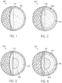
- FIGS. 1-4 show various embodiments of multi-piece golf balls in accordance with this disclosure.
- FIG. 1 shows a first golf ball 100 having aspects in accordance with this disclosure.
- Golf ball 100 is a two-piece golf ball.
- golf ball 100 includes cover layer 110 substantially surrounding core 120.
- Cover layer 110 may be formed of any golf ball cover material known in the art, which in some embodiments maybe a relatively soft but durable material.
- cover layer 110 may be formed of a material that compresses/flexes when struck by a golf club, in order to provide spin of the ball and feel to the player. Although relatively soft, the material may also be durable, in order to withstand scuffing from the club and/or the golf course.
- FIG. 1 illustrates the outer surface of cover layer 110 as having a generic dimple pattern. While the dimple pattern on golf ball 100 may affect the flight path of golf ball 100, any suitable dimple pattern may be used with the disclosed embodiments. In some embodiments, golf ball 100 may be provided with a dimple pattern including a total number of dimples between approximately 250 and 450.
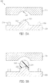
- FIG. 2 shows a second golf ball 200 having aspects in accordance with this disclosure.
- Golf ball 200 includes a core 230, an mantle layer 220 substantially surrounding core 230, and an outer cover layer 210 substantially surrounding mantle 220.
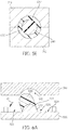
- FIG. 3 shows a third golf ball 300 having aspects in accordance with this disclosure, where third golf ball 300 has a three-piece construction.
- Three-piece golf ball 300 includes a first inner core 330, a first outer core 320 substantially surrounding first inner core 330, and a first cover layer 310 substantially surrounding first outer core 320.
- FIG. 4 shows a fourth golf ball 400 having aspects in accordance with this disclosure, where fourth golf ball 400 has a four-piece construction.
- Golf ball 400 includes a second inner core 440, a second outer core 430 substantially surrounding second inner core 440, an inner cover layer 420 substantially surrounding outer core 430, and an outer cover layer 410 substantially surrounding inner cover layer 420.
- core refers to at least one of the innermost structural components of the golf ball.
- the term core may therefore refer, with reference to FIG. 3 but applicable to any embodiment discussed herein, to (1) first inner core 330 only, (2) both first inner core 330 and first outer core 320 collectively, or (3) first outer core 320 only.
- the term core may also encompass more than two layers if, for example, an additional structural layer is present between first inner core 330 and first outer core 320 or encompassing first outer core 320.
- a core may be formed from thermosetting or thermoplastic materials, such as polyurethane, polyurea, partially or fully neutralized ionomers, thermosetting polydiene rubber, such as polybutadiene, polyisoprene, ethylene propylene diene monomer rubber, ethylene propylene rubber, natural rubber, balata, butyl rubber, halobutyl rubber, styrene butadiene rubber or any styrenic block copolymer, such as styrene ethylene butadiene styrene rubber, etc., metallocene or other single site catalyzed polyolefin, polyurethane copolymers, e.g. with silicone.
- thermosetting polydiene rubber such as polybutadiene, polyisoprene, ethylene propylene diene monomer rubber, ethylene propylene rubber, natural rubber, balata, butyl rubber, halobutyl rubber, styrene buta
- compositions for portions of a golf ball may incorporate one or more polymers.
- suitable additional polymers include, but are not limited to, the following: thermoplastic elastomer, thermoset elastomer, synthetic rubber, thermoplastic vulcanizate, copolymeric ionomer, terpolymeric ionomer, polycarbonate, polyolefin, polyamide, copolymeric polyamide, polyesters, polyvinyl alcohols, acrylonitrile-butadiene-styrene copolymers, polyarylate, polyacrylate, polyphenylene ether, impact-modified polyphenylene ether, high impact polystyrene, diallyl phthalate polymer, metallocene catalyzed polymers, styreneacrylonitrile (SAN) (including olefin-modified SAN and acrylonitrile-
- SAN styreneacrylonitrile
- Suitable polyamides for use as an additional material in compositions within the scope of the present invention also include resins obtained by: (1) polycondensation of (a) a dicarboxylic acid, such as oxalic acid, adipic acid, sebacic acid, terephthalic acid, isophthalic acid or 1,4-cyclohexanedicarboxylic acid, with (b) a diamine, such as ethylenediamine, tetramethylenediamine, pentamethylenediamine, hexamethylenediamine or decamethylenediamine, 1,4-cyclohexyldiamine or m-xylylenediamine; (2) a ring-opening polymerization of cyclic lactam, such as ⁇ -caprolactam or ⁇ -laurolactam; (3) polycondensation of an aminocarboxylic acid, such as 6-aminocaproic acid, 9-aminononanoic acid, 11-aminoundecanoic
- polyester elastomers marketed under the tradename SKYPEL by SK Chemicals of Republic of Korea, or diblock or triblock copolymers marketed under the tradename SEPTON by Kuraray Corporation of Kurashiki, Japan, and KRATON by Kraton Polymers Group of Companies of Chester, United Kingdom. All of the materials listed above can provide for particular enhancements to ball layers prepared within the scope of the present invention.
- lonomers also are well suited as a golf ball material, by itself or in a blend of compositions.
- Suitable ionomeric polymers include ⁇ -olefin/unsaturated carboxylic acid copolymer-type ionomeric or terpolymer-type ionomeric resins.
- Copolymeric ionomers are obtained by neutralizing at least a portion of the carboxylic groups in a copolymer of an ⁇ -olefin and an ⁇ , ⁇ -unsaturated carboxylic acid having 3 to 8 carbon atoms, with a metal ion.
- Suitable ⁇ -olefins include ethylene, propylene, 1-butene, and 1-hexene.
- suitable unsaturated carboxylic acids include acrylic, methacrylic, ethacrylic, ⁇ -chloroacrylic, crotonic, maleic, fumaric, and itaconic acid.
- Copolymeric ionomers include ionomers having varied acid contents and degrees of acid neutralization, neutralized by monovalent or bivalent cations discussed above.
- Terpolymeric ionomers are obtained by neutralizing at least a portion of carboxylic groups in a terpolymer of an ⁇ -olefin, and an ⁇ , ⁇ -unsaturated carboxylic acid having 3 to 8 carbon atoms, and an ⁇ , ⁇ -unsaturated carboxylate having 2 to 22 carbon atoms with metal ion.
- suitable ⁇ -olefins include ethylene, propylene, 1-butene, and 1-hexene.
- suitable unsaturated carboxylic acids include acrylic, methacrylic, ethacrylic, ⁇ -chloroacrylic, crotonic, maleic, fumaric, and itaconic acid.
- Suitable ⁇ , ⁇ -unsaturated carboxylates include methyl acrylate, ethyl acrylate and n-butyl acrylate.
- Terpolymeric ionomers include ionomers having varied acid contents and degrees of acid neutralization, neutralized by monovalent or bivalent cations as discussed above.
- suitable ionomeric resins include those marketed under the name SURLYN® manufactured by E.I. du Pont de Nemours & Company of Wilmington, Del., and IOTEK® manufactured by Exxon Mobil Corporation of Irving, Tex.
- Silicone materials also are well suited for use in golf balls, either alone or as a component in a blend of materials. These can be monomers, oligomers, prepolymers, or polymers, with or without additional reinforcing filler.
- One type of silicone material that is suitable can incorporate at least 1 alkenyl group having at least 2 carbon atoms in their molecules. Examples of these alkenyl groups include, but are not limited to, vinyl, allyl, butenyl, pentenyl, hexenyl and decenyl.
- the alkenyl functionality can be located at any location of the silicone structure, including one or both terminals of the structure.
- the remaining (i.e., non-alkenyl) silicon-bonded organic groups in this component are independently selected from hydrocarbon or halogenated hydrocarbon groups that contain no aliphatic unsaturation.
- hydrocarbon or halogenated hydrocarbon groups that contain no aliphatic unsaturation.
- Non-limiting examples of these include: alkyl groups, such as methyl, ethyl, propyl, butyl, pentyl and hexyl; cycloalkyl groups, such as cyclohexyl and cycloheptyl; aryl groups, such as phenyl, tolyl and xylyl; aralkyl groups, such as benzyl and phenethyl, and halogenated alkyl groups, such as 3,3,3-trifluoropropyl and chloromethyl.
- silicone material suitable for use in the present invention is one having hydrocarbon groups that lack aliphatic unsaturation.
- suitable silicones for use in making compositions of the present invention include the following: trimethylsiloxy-endblocked dimethylsiloxane-methylhexenylsiloxane copolymers; dimethylhexenlylsiloxy-endblocked dimethylsiloxane-methylhexenylsiloxane copolymers; trimethylsiloxy-endblocked dimethylsiloxane-methylvinylsiloxane copolymers; trimethylsiloxy-endblocked methylphenylsiloxane-dimethylsiloxane-methylvinylsiloxane copolymers; dimethylvinylsiloxy-endblocked dimethylpolysiloxanes; dimethylvinylsiloxy-endblocked dimethylsiloxane-methylvinylsiloxane copolymers; dimethylvinylsiloxy-
- silicones suitable for use in compositions within the scope of the present invention include Silastic by Dow Corning Corp. of Midland, Mich., Blensil by GE Silicones of Waterford, N.Y., and Elastosil by Wacker Silicones of Adrian, Mich.
- epoxy functional copolymers include ESBS A1005, ESBS A1010, ESBS A1020, ESBS AT018, and ESBS AT019, marketed by Daicel Chemical Industries, Ltd. of Osaka, Japan.
- first inner core 330 and first outer core 320 of golf ball 300 and second inner core 440 and second outer core 430 of golf ball 400 may be formed by a multi-step process.
- first outer core 320 and second outer core 430 may be first formed as separately molded sections that are subsequently molded about first inner core 330 and second inner core 440, respectively, to form first outer core 320 about first inner core 330 and to form second outer core 430 about second inner core 440.
- thermoset materials such as butadiene rubber (BR)
- molded sections When made of thermoset materials, such as butadiene rubber (BR), such molded sections may be produced in the form of hemispherical sections or cups which are configured to encase a previously molded inner core when the hemispherical sections are molded about the inner core, causing to the hemispherical sections to join together to form the outer core.
- the molded combination of outer core and inner core may be further processed to manufacture a golf ball, such as, for example, by grinding off any molding flash, tumbling the outer core/inner core combination to roughen its outer surface, and to apply further materials, such as the materials for a mantle and/or a cover.
- FIG. 5A depicts a side sectional view of a conventional mold 500 for producing a hemispherical section of an outer core.
- a hemispherical section may be matched with a corresponding hemispherical section.
- the two hemispherical sections may be subsequently molded together to produce an outer core, such as outer core 320 of golf ball 300 or outer core 430 of golf ball 400, for example.
- Another part or parts may be positioned between the hemispherical portions as well prior to being molded together.
- Mold 500 may include an upper mold plate 510 and a lower mold plate 520 for compression molding a material.
- Lower mold plate 520 may include a projection 522 while upper mold plate 510 may include a cavity 512 that is sized and shaped to receive projection 522.
- Projection 522 has a shape corresponding to an inner surface of a hemispherical section where an inner core would be located. In such embodiments, projection 522 may be provided as a rounded projection.
- Cavity 512 has a shape corresponding to an outer surface of the hemispherical section.
- Lower mold plate 520 may include lugs 526 or other devices that provide a gap between upper mold plate 510 and lower mold plate 520 when mold 500 is closed. As will be recognized by those of ordinary skill in the art, lugs 526 may instead be located on upper mold plate 510 or on both upper mold plate 510 and lower mold plate 520.
- a slug 530 is placed within mold 500, between projection 522 and cavity 512, which may serve as a material to be molded.
- Slug 530 may be a material suitable for molding a hemispherical section subsequently used to mold an outer core, such as a thermoset material or any of the other materials discussed above.
- Slug 530 may have a shape suitable for use in mold 500, such as a dome shape, cylindrical shape, or other suitable shape.
- a surface of slug 530 facing projection 522 may be concave with a shape corresponding to projection 522, as shown in FIG. 5B .
- the surface of slug 530 facing projection 522 may be flat, or may have other shapes used in the art.
- the surface of slug 530 facing projection 522 may be shaped to assist with positioning slug 530 on projection 522.
- the surface of slug 530 facing projection 522 may have a concave shape, as shown in FIG. 5B .
- projection 522 may include a mechanical fastening device 524 to attach slug 530 to projection 522 to a degree.
- mechanical fastening device 524 may be a pin that penetrates the material of slug 530, as shown in FIG. 5B , although other fastening devices may be used.
- the length of mechanical fastening device 524 may be from 0.5 mm to 5 mm, or from 0.5 mm to 3 mm.
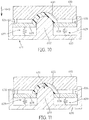
- mold 500 is closed so that upper mold plate 510 and lower mold plate 520 are brought together, as shown in FIG. 5C .
- Upper mold plate 510 and lower mold plate 520 may move along guide rods, be hinged, or actuated by other devices (not shown) enabling at least one of upper mold plate 510 and lower mold plate 520 to move relative to the other to close mold 500.
- Closing mold 500 and pressing upper mold plate 510 against lower mold plate 520 with a pressure ranging between about 85 kg/cm 2 and about 170 kg/cm 2 causes slug 530 to be deformed between upper mold plate 510 and lower mold plate 520, particularly on the outer surface of projection 522 and within cavity 512, although slug 530 may bulge outward to a degree within a gap provided between upper mold plate 510 and lower mold plate 520.
- at least one of upper mold plate 510 and lower mold plate 520 may be heated to assist with curing of slug 530.
- a mold may include one or more alignment pins and one or more holes corresponding to the alignment pins.
- the alignment pins may assist with alignment of mold plates during a molding process.
- Such alignment pins may be provided in a mold instead of lugs 526.
- FIG. 14A an example of a mold 1000 for producing a hemispherical section of an outer core is shown.
- Mold 1000 may include an upper mold plate 1010 and a lower mold plate 1020 for compression molding a material.
- Lower mold plate 1020 may include a projection 1022 while upper mold plate 1010 may include a cavity 1012 that is sized and shaped to receive projection 1022.
- Lower mold plate 1020 may include one or more alignment pins 1026 or other devices that mate with upper mold plate 1010 to assist with alignment between upper mold plate 1010 and lower mold plate 1020.
- upper mold plate 1010 may include one or more alignment holes 1029 that correspond to the one or more alignment pins 1026 of lower mold plate 1020.
- alignment pins 1026 and alignment holes 1029 may assist in providing projection 1022 and cavity 1012 in a concentric or coaxial alignment when mold 1000 is closed.
- alignment pins 1026 may instead be located on upper mold plate 1010 and alignment holes 1029 may be provided on lower mold plate 1020, or alignment pins 1026 and alignment holes 1029 may be provided on both upper mold plate 1010 and lower mold plate 1020.
- a slug 1030 is placed within mold 1000, between projection 1022 and cavity 1012, which may serve as a material to be molded.
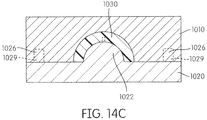
- mold 1000 is closed, as discussed above in regard to mold 500 in FIG. 5C , so that upper mold plate 1010 and lower mold plate 1020 are brought together, as shown in FIG. 14C .
- slug 530 is deformed into a particular shape, such as a hemispherical section 632.
- shape of cavity 1012 and projection 1022 of mold 1000 in FIG. 14C may deform slug 1030 into a particular shape, such as a hemispherical section 632.
- a hemispherical section 632 may have a cup-like shape.
- Hemispherical section 632 may, for example, form substantially half of an outer core, such as first outer core 320 and second outer core 430, above, that is subsequently molded from two hemispherical sections 632.
- a second hemispherical section 632 is molded and, as shown in FIG. 5D , hemispherical sections 632 are arranged to encase a previously molded inner core 640. Hemispherical sections 632 and inner core 640 are then placed between an upper mold 710 and a lower mold 712, as shown in FIG. 5E , with inner core 640 placed between hemispherical sections 632. Upper mold 710 and lower mold 712 are subsequently pressed together to join hemispherical sections 632 to form a completed core, which has an outer core that encases inner core 640, such as outer core 320 of golf ball 300 shown in FIG. 3 or outer core 430 of golf ball 400 shown in FIG. 4 .
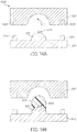
- a slug 530 is properly located and centered within mold 500 during the molding operation. If slug 530 is not properly located within mold 500 during the molding operation, a hemispherical section 632 may be produced that has an unsatisfactory shape.
- a slug 530 placed on top of projection 522 may move relative to projection 522 and cavity 512 before molding is complete.
- slug 530 may move in direction 10, such as by slipping off of an upper portion 527 of projection 522.
- Such a movement may result in the formation of a hemispherical section (not shown) having an undesirable shape because more of slug 530 may be located on a first side 523 of projection 522 than on a second side 525 of projection 522 after slug has been pressed between upper mold plate 510 and lower mold plate 520.
- the molded hemispherical section 632 may be thicker on one side than another, which will cause an inner core to be off-center within the golf ball.
- an inner core 640 may be offset within an outer core 650 after a molding operation.
- the center 642 of inner core 640 may be offset from a center 652 of outer core 650.
- Center 652 may also be the center of a golf ball that includes inner core 640 and outer core 650.
- Such an off-center inner core would likely provide less than optimal results for a golf ball. For example, the flight performance in USGA symmetry test may not be satisfactory.
- the embodiments discussed herein advantageously address this issue by providing a machine and method that minimizes or eliminates movement of molding material from its proper position during a molding process.
- One way to address this issue is to reduce the distance between the upper portion 527 of projection 522 and a surface 529 of lower mold plate 520.
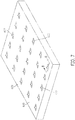
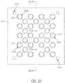
- FIG. 7 an embodiment of a molding plate 620 for molding hemispherical sections is shown.
- Molding plate 620 has an upper surface 623 and a plurality of projections 622 protruding through upper surface 623. Projections 622 and upper surface 623 are configured to move relative to one another.
- FIG. 8 a cross-sectional view of one of the projections 622 of molding plate 620 is shown, along with an upper mold plate 610 having one or more cavities 612. Each pair of cavities 612 and projections 622 may form a complete mold cavity. Cavities 612 of upper mold plate 610 correspond to projections 622 so that projections 622 are inserted into cavities 612 when upper mold plate 610 and mold plate 620 are brought together during a molding operation.
- Mold plate 620 includes a movable insert 628.
- Movable insert 628 may be in the form of a flat plate that includes an aperture 627 through which projection 622 extends.
- movable insert 628 surrounds projection 622, such as in a plane, when projection 622 extends through the aperture of movable insert 628.
- movable insert 628 may be located proximate to an upper surface 625 of projection 622.
- projection 622 may extend above movable insert 628 by a predetermined amount.
- upper surface 625 of projection 622 may extend above movable insert 628 by approximately 0.5 mm to 7 mm. In another example, upper surface 625 of projection 622 may extend above movable insert 628 by approximately 1 mm to 5 mm. In another example, upper surface 625 of projection 622 may extend above movable insert 628 by approximately 1 mm to 3 mm. It may not be desirable for upper surface 625 of projection 622 to extend above movable insert 628 by more than 7 mm because a slug may slip off of projection 522 and produce an off-centered core.
- Movable insert 628 may be joined to mold plate 620 via one or more biasing devices 629.
- Biasing devices 629 may be, for example, a spring, that biases movable insert 628 away from a lower surface 612 of mold plate 620 towards upper mold plate 610.
- Helical springs, coil springs, compression springs and other types of springs known in the art may be used.
- the spring constant of springs used for biasing movable insert 628 may be considered in view of the weight of movable insert 628.
- lugs 626 may serve as anchors for the spring to assist with attaching biasing device 629 to movable insert 628. In this regard, lugs 626 may provide this anchoring function in addition to their spacing function between upper mold plate 510 and lower mold plate 520 or alternatively to their spacing function.
- biasing devices 629 may be an actuated connection.
- biasing devices 629 may be motorized and powered by a motor that causes movable insert 628 to move relative to mold plate 620.
- biasing devices 629 may be pneumatic, hydraulic, or powered by other means known in the art.
- Movable insert 628 may also include one or more lugs 626 or other devices that provide a gap between upper mold plate 610 and mold plate 620 when they are closed together, although lugs 626 may instead be located on upper mold plate 610 or on both upper mold plate 610 and mold plate 620.
- a slug 630 may be inserted between upper mold plate 610 and mold plate 620.
- slug 630 may be located on an upper surface 625 of projection 622.
- a lower surface of slug 630 facing movable insert 628 may contact an upper surface of movable insert 628 that faces upper mold plate 610, as shown in FIG. 9 .
- projection 622 may include a mechanical fastening device 624, as discussed above, to assist in maintaining the location and positioning of slug 630.
- movable insert 628 is located proximate to upper surface 625 of projection 622 when upper mold plate 610 and mold plate 620 are separated from one another, movable insert 628 is also located proximate to slug 630.
- slug 630 may already contact movable insert 628, or move into contact with movable insert 628, to essentially provide a support for slug 630 or a stop for unintended motion of slug 630.
- movable insert 628 does not permit slug 630 to move by a substantial amount during a molding process and advantageously addresses the issue of slugs movable during a molding process and producing unsatisfactory hemispherical sections.
- movable insert 628 When upper mold plate 610 and lugs 626 are not in contact so that movable insert 628 is fully extended, movable insert 628 may be positioned at a first position, such as a first upper position, that provides a gap 20 between movable insert 628 and slug 630. Gap 20 may have a size such that slug 630 may move by an amount that does not substantially affect the molded shape of a hemispherical section, and the eventual centering of an inner core within the hemispherical section, slug 630 comes into contact with movable inset 628 and ceases to move.
- movable insert 628 may be at a second position, such as a second upper position lower than the first upper position, at which movable insert 628 is in contact with slug 630.
- slug 630 may be substantially prevented from lateral and/or rotational movement relative to projection 622.
- upper mold plate 610 and mold plate 620 may be brought together to commence a compression molding operation to mold slug 630 into a hemispherical section.
- mold plate 620 and movable insert 628 may move relative to one another. For example, as shown in FIG. 10 , when upper mold plate 610 and mold plate 620 are closed together, upper mold plate 610 may come into contact (directly with one another or indirect via lugs 626) with, and press against, movable insert 628, causing movable insert 628 to be depressed downwards in direction 640 towards lower surface 621 of mold plate 620.
- lower surface 621 of mold plate 620 may serve as a first surface and surface 623, which is formed by movable insert 628, may serve as a second surface, with the first surface and second surface moving relative to one another during a molding operation.
- upper mold plate 610 directly contacts movable insert 628 (such as when lugs 626 are not present)
- a gap may be formed between upper mold plate 610 and movable insert 628, within which slug 630 may be deformed and molded into a hemispherical section. Such movement may cause movable insert 628 to withdraw within mold plate 620 or move relative to projection 622.
- biasing devices 629 may overcome the resistance of biasing devices 629, when biasing devices 629 are energy storage-type devices, such as springs, or biasing devices 629 may be driven downwards according to the downward motion of movable insert 628 when biasing devices 629 are actuated devices such as pneumatically-, hydraulically- or motor-driven pistons.
- upper mold plate 610 and mold plate 620 are completely closed together with a pre-selected applied pressure to complete the compression molding of slug 630 into a hemispherical section.
- the applied pressure may be, for example, a pressure ranging between about 85 kg/cm 2 and about 170 kg/cm 2 .
- movable insert 628 has been pushed into an interior space within mold plate 620 so that slug 630 may be molded around projection 622.
- movable insert 628 may come into contact with mold plate 620.
- the resultant hemispherical section has a recess 631 generally in the shape of projection 622 that is configured to receive an inner core.
- movable insert 628 is initially at a position to minimize or prevent movement of slug 630 that would render a molded hemispherical section unsatisfactory but the initial position is not conducive for forming the cup-like shape and recess 631 of a hemispherical section.
- movable plate 628 is driven into the interior space within mold plate 620 when upper mold plate 610 and mold plate 620 are brought together during a molding operation. This movement of movable insert 628 permits slug 630 to be deformed around projection 622 so that slug 630 may be molded into a hemispherical section having a recess 631 suitable for receiving an inner core.
- slug 630 is molded into a hemispherical section, such as hemispherical section 632 shown in FIG. 5D
- a second hemispherical section is molded and the two hemispherical sections are joined together to form a completed core with an outer core about the inner core, as shown in FIG. 5E .
- the resulting core combination may then be processed in the manner discussed above to produce a golf ball.
- movable insert 628 may be provided as a single plate that surrounds all projections 622 shown in FIG. 7 so that movable insert 628 moves relative to all projections 622 simultaneously.
- discrete groups of projections 622 may be surrounded with a movable insert 628, with mold plate 620 including a plurality of movable inserts 628 for multiple groups of projections 622.
- each projection 622 may be individually provided with a movable insert 628 that independently moves relative to other movable inserts 622.
- mold plate 620 may include a plurality of projections 622.
- a molding plate 620 may be provided with a single projection 622 and a single movable insert 628 surrounding the projection 622.
- a mold may manufacture corresponding sets of hemispherical sections.
- a mold 800 may include an upper mold plate 810 with a cavity 812, a lower mold plate 830 with a cavity 832, and a midplate 820.
- Midplate 820 may include a first projection 822 and a second projection 823 that are each respectively surrounded by a first movable insert 828 and a second movable insert 827, through which the projections 822, 823 extend.
- Movable inserts 828, 827 may be joined to midplate 820 by biasing devices 829, as discussed above.
- a slug (not shown in FIG.
- first projection 822 opposite cavity 812 may then be placed upon first projection 822 opposite cavity 812 and a slug may be placed within cavity 832.
- the slug may contact movable insert 828, similarly to slug 630 in FIG. 9 .
- upper mold plate 810 may be actuated to move in direction 840 and contact the first movable insert 828 opposite to upper mold plate 810, causing the first movable insert 828 to move relative to midplate 820 as a slug is molded within a space provided between the first projection 822 and cavity 812.
- lower mold plate 830 may move in direction 842 and contact the second movable insert 827 opposite to lower mold plate 830, causing the second movable insert 827 to move upward as a slug is molded within a space provided between the second projection 823 and cavity 832.
- Hemispherical sections produced by mold 800 may subsequently be placed around an inner core within a mold to form an outer core/inner core combination, as described in the example of FIG. 5E .
- molded hemispherical sections are kept in cavity 812 and cavity 832, respectively.
- Midplate 820 may be removed from mold 800 and an inner core (not shown) may be placed within at least one top a hemispherical section in cavity 812 and a hemispherical section in cavity 832 to form an outer core/inner core combination.
- molded material such as the material of the slugs
- molded material may accumulate on the surfaces and walls of a mold. Further, even though a mold may have relatively tight tolerances and relatively small gaps between surfaces, molded material may also be pressed into the small gaps between surfaces. Such accumulation of mold material in undesired locations may affect the precision of the mold process and may even hinder or jam the movement of mold components.
- a projection of a mold plate may include a coating to facilitate the release of a molded hemispherical section from a projection.
- a mold plate 920 may include a projection, a movable insert 928 joined to mold plate 920 by one or more biasing devices 929, as described above.
- a release coating 950 such as Teflon®, EFTE, or blue fluoropolymer film, may be provided on projection 922, and/or movable insert 928, and/or on walls of mold plate 920 to facilitate the release of a molded hemispherical section from projection 922.
- Coating 950 may also minimize accumulation of molded material, such as material from slugs, that otherwise might accumulated in the space between projection 922 and movable insert 928, which could lead to jamming of the movable insert 928 as the material from the slugs cures.
- Coating 950 may be made from a material with a low coefficient of friction.
- Projection 922 may also include a mechanical fastening device 924, as discussed above, which may extend through and above coating 950 so that mechanical connecting device 924 is at least partially uncoated by coating 950.
- Mechanical fastening device 924 may be fully coated by coating 950. In one embodiment, mechanical fastening device 924 may extend through and above coating 950 so that mechanical fastening device 924 is at least partially uncoated by coating 950.
- Molding plate may be provided as a lower mold plate 1120 that includes one or more projections 1122 that protrude through an upper surface 1123 of movable insert 1128 as shown in FIG. 15 .
- FIG. 16 a cross-sectional view of one of the projections 1122 of molding plate 1120 is shown, along with an upper mold plate 1110 having one or more cavities 1112 corresponding to projections 1122. Each pair of cavities 1112 and projections 1122 may form a complete mold cavity.
- Lower mold plate 1120 may include a movable plate 1128. Movable plate 1128 may form top surface 1123 of lower mold plate 1120. Movable plate 1128 may be in the form of a flat plate that includes an aperture 1127 through which projection 1122 extends. As a result, movable plate 1128 may surround projection 1122, such as in a plane, when projection 1122 extends through the aperture of movable plate 1128. Further, in the example of FIGS.
- movable plate 1128 may be provide as a plate that extends to the edges of lower mold plate 1120, instead of being provided as an insert that fits within a recess of lower mold plate 1120, as shown in the example of FIGS. 7 and 8 .
- movable plate 1128 may be located proximate to an upper surface 1125 of projection 1122.
- projection 1122 may extend above movable plate 1128 by a predetermined amount, such as by extending above upper surface 1123.
- upper surface 1125 of projection 1122 may extend above movable plate 1128 by approximately 0.5 mm to 7 mm.
- upper surface 1125 of projection 1122 may extend above movable plate 1128 by approximately 1 mm to 5 mm.
- upper surface 1125 of projection 1122 may extend above movable plate 1128 by approximately 1 mm to 3 mm.
- upper surface 1125 of projection 1122 may desirably extend above movable plate 1128 by no more than 7 mm, because a slug may slip off of projection 1122 and produce an off-centered core.
- Movable plate 1128 may be joined to lower mold plate 1120 via one or more biasing devices 1129.
- biasing devices 1129 may be, for example, a spring, that biases movable plate 1128 away from a lower surface 1121 of lower mold plate 1120 towards upper mold plate 1110.
- biasing devices 1129 may be an actuated connection, as discussed above.
- biasing devices 1129 may be actuated devices, such as pneumatically-, hydraulically- or motor-driven pistons.
- upper mold plate 1110 and lower mold plate 1120 may include alignment pins and one or more holes corresponding to the alignment pins.
- the alignment pins may assist with alignment of mold plates during a molding process.
- upper mold plate 1110 may include one or more alignment pins 1126 or other devices that mate with lower mold plate 1120 to assist with alignment between upper mold plate 1110 and lower mold plate 1120.
- movable plate 1128 may include one or more alignment holes 1133 that correspond to the one or more alignment pins 1126 of upper mold plate 1110.
- Such alignment pins 1126 and alignment holes 1133 may assist in providing projection 1122 and cavity 1112 in a concentric or coaxial alignment when the mold is closed.
- alignment pins 1126 may instead be located on movable plate 1128 and alignment holes 1133 may be provided on upper mold plate 1110, or alignment pins 1126 and alignment holes 1133 may be provided on both upper mold plate 1110 and lower mold plate 1120.
- alignment pins 1126 may be provided on movable plate 1128 to serve as anchors for biasing device 1129 to assist with attaching biasing device 1129 to movable plate 1128.
- a slug 1130 may be inserted between upper mold plate 1110 and lower mold plate 1120.
- slug 1130 may be located on an upper surface 1125 of projection 1122.
- a lower surface of slug 1130 facing movable plate 1128 may contact an upper surface 1123 of movable plate 1128 that faces upper mold plate 1110.
- lateral portions 1131 of slug 1130 may contact movable plate 1128, as shown in FIG. 17 .
- Projection 1122 may include a mechanical fastening device 1124, as discussed above, to assist in maintaining the location and positioning of slug 1130.
- upper mold plate 1110 and lower mold plate 1120 may be brought together to commence a compression molding operation to mold slug 1130 into a hemispherical section.
- lower mold plate 1120 and movable plate 1128 may move relative to one another. For example, as shown in FIG. 18 , when upper mold plate 1110 and lower mold plate 1120 are closed together, upper mold plate 1110 may come into contact with, and press against, movable plate 1128, causing movable plate 1128 to be depressed downwards in direction 1140 towards lower surface 1121 of lower mold plate 1120.
- Alignment pins 1126 are inserted within alignments holes 1133 when upper mold plate 1110 and movable plate 1128 come into contact.
- lower surface 1121 of lower mold plate 1120 may serve as a first surface and surface 1123, which is formed by movable plate 1128, may serve as a second surface, with the first surface and second surface moving relative to one another during a molding operation.
- This movement of movable plate 1128 relative to lower mold plate 1120 may overcome the resistance of biasing devices 1129, when biasing devices 1129 are energy storage-type devices, such as springs, or biasing devices 1129 may be driven downwards according to the downward motion of movable plate 1128.
- upper mold plate 1110 and lower mold plate 1120 are completely closed together with a pre-selected applied pressure to complete the compression molding of slug 1130 into a hemispherical section.
- the applied pressure may be, for example, a pressure ranging between about 85 kg/cm 2 and about 170 kg/cm 2 .
- movable plate 1128 has been pushed against lower mold plate 1120, as shown in FIG. 19 . This movement of movable plate 1128 permits slug 1130 to be deformed around projection 1122 so that slug 1130 may be molded into a hemispherical section having a recess suitable for receiving an inner core.
- slug 1130 is molded into a hemispherical section, such as hemispherical section 632 shown in FIG. 5D
- a second hemispherical section is molded and the two hemispherical sections are joined together to form a completed core with an outer core about the inner core, as shown in FIG. 5E .
- the resulting core combination may then be processed in the manner discussed above to produce a golf ball.
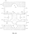
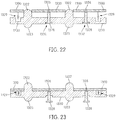
- FIG. 20 an embodiment of a mold is shown that includes an upper mold plate 120 with a first cavity 1212, a lower mold plate 1230 with a second cavity 1232, and a midplate 1220 that includes a movable plate 1228 connecting to midplate 1220 with one or more biasing devices 1229.
- Upper mold plate 1210 may include one or more alignment pins 1226.
- Movable plate 1228 may include one or more alignment holes 1227
- midplate 1220 may include one or more alignment holes 1225
- lower mold plate 1230 may include one or more alignment holes 1233 to receive alignment pins 1226 when the mold is closed, although the alignment pins 1226 may instead be located on other components of the mold, such as lower mold plate 1230.
- Midplate 1220 may include a first projection 1222 and a second projection 1223.
- First projection 1222 may have a first height 1244 and second projection 1223 may have a second height 1246.
- First height 1244 of first projection 1222 may be greater than second height 1246 of second projection 1223. For instance, because first projection 1222 extends through movable plate 1228 and the thickness of movable plate 1228, first height 1244 may be greater than second height 1246.
- first height 1244 of first projection 1222 may be greater than second height 1246 of second projection 1223 by the thickness of movable plate 1228.
- first height 1244 of first projection 1222 may be greater than second height 1246 of second projection 1223 by the thickness of movable plate 1228.
- Such an arrangement in when first height 1244 is greater than second height 1246 by only the thickness of movable plate 1228 may provide hemispherical sections that are substantially the same, which in turn may assist in forming a dual-core and a golf ball having the dual-core that have a desired performance and quality.
- FIG. 21 a top view of a movable plate 1300 is shown.
- Movable plate 1300 may be used similarly to the movable plate 1228 of FIG. 20 .
- Movable plate 1300 may include one or more apertures 1320 through which one or more first projections 1320 extend.
- Movable plate 1300 may also include one or more alignment holes 1324 to receive alignment pins of a mold plate (not shown).
- FIG. 22 which is a side cross-sectional view along line 23-23 in FIG. 21 , movable plate 1300 may be part of a midplate 1330 that includes the one or more first projections 1322 as well as one or more second projections 1323.
- Movable plate 1300 may be connected to midplate 1330 by one or more biasing devices 1329 that bias movable plate 1300 upwards in a direction away from midplate 1330. Movable plate 1300 may be further connected to midplate 1330 by one or more pins 1328. Pins 1328 may fit within recesses 1332 provided in midplate 1330 and may have an enlarged head that extends in one or more lateral directions, as shown in FIG. 22 . For example, pins 1328 may have heads substantially formed in the shape of a "T,” as shown in FIG. 22 .
- pin 1328 may be used to control the distance between the upper surface of movable plate 1300 and the top surface of a projection 1322 and affect the stability of a slug (not shown) placed upon the top surface of projection 1322.
- Pins 1328 may be connected to movable plate 1300 by, for example, fasteners 1326, such as screws, bolts, or other fasteners used in the art.
- pins 1328 may be formed with movable plate 1300 using a single-piece construction.
- a mold plate When a mold including midplate 1330 is closed, a mold plate may come into contact with movable plate 1300 and force movable plate 1300 in a direction towards midplate 1330. As shown in FIG. 23 , movable plate 1300 may be forced into contact with midplate 1330. When this occurs, pins 1328 may also be forced downwards to extend out of recesses 1332. Once a molding operation is complete, the mold may be opened, which releases the pressure upon movable plate 1300 and permits biasing devices 1329 to move movable plate 1300 in a direction away from midplate 1330, such as to the position shown in FIG. 22 .
- Inner cores were made from a HPF 2000 and HPF AD 1035 blend (HPF and HPF AD 1035 are trade names of ionomeric resins by E. I. DuPont de Nemours and Co.) and outer cores were made from a rubber compound of TAIPOLTM BR 150 (TAIPOLTM BR 150 is a trade name of a rubber produced by Taiwan Synthetic Rubber Corporation).
- Inner cores were made by injection molding, although compression molding could also be applied. The temperature of the injection molding machine was set in a range of 190°C to 220°C. Outer cores were made by compression molding, and the temperature of the compression molding machine was set in a range of 130°C to 170°C.
- Examples One hundred pieces of an outer core/inner core combination were made by a compression mold including a midplate with a movable plate ("Examples”). One hundred pieces of an outer core/inner core combination were made by a compression mold without a midplate with a movable plate (“Comparative Examples”). After the cores were finished and cooled down for at least 4 hours, all cores were cut into halves by a cutter. If the inner core was off-center in the outer core by not more than 0.8 mm, it was marked as OK. If the inner core was off-center in the outer core by more than 0.8 mm, it was marked as NG. The result were as follows: Examples Comparative Examples movable insert in compression mold Yes No Balls Marked "OK” 98 92 Balls Marked "NG” 2 8 Off-center rate 2% 8%
- a midplate with a movable plate may advantageously reduce the off-center rate of molded cores to a satisfactory extent.
Landscapes
- Engineering & Computer Science (AREA)
- Mechanical Engineering (AREA)
- Health & Medical Sciences (AREA)
- General Health & Medical Sciences (AREA)
- Physical Education & Sports Medicine (AREA)
- Robotics (AREA)
- Moulds For Moulding Plastics Or The Like (AREA)
Applications Claiming Priority (1)
| Application Number | Priority Date | Filing Date | Title |
|---|---|---|---|
| US13/456,930 US8974218B2 (en) | 2012-04-26 | 2012-04-26 | Mold plate and method of molding golf ball core |
Publications (3)
| Publication Number | Publication Date |
|---|---|
| EP2656883A2 EP2656883A2 (en) | 2013-10-30 |
| EP2656883A3 EP2656883A3 (en) | 2014-07-02 |
| EP2656883B1 true EP2656883B1 (en) | 2017-02-08 |
Family
ID=48193089
Family Applications (1)
| Application Number | Title | Priority Date | Filing Date |
|---|---|---|---|
| EP13164661.4A Not-in-force EP2656883B1 (en) | 2012-04-26 | 2013-04-22 | Mold and method of molding golf ball core |
Country Status (5)
| Country | Link |
|---|---|
| US (2) | US8974218B2 (enExample) |
| EP (1) | EP2656883B1 (enExample) |
| JP (1) | JP5850506B2 (enExample) |
| CN (1) | CN103496073B (enExample) |
| TW (1) | TWI505854B (enExample) |
Families Citing this family (5)
| Publication number | Priority date | Publication date | Assignee | Title |
|---|---|---|---|---|
| US9211662B2 (en) * | 2012-03-30 | 2015-12-15 | Nike, Inc. | Mold with midplate and method of molding golf ball |
| EP3139760B1 (de) * | 2014-05-06 | 2020-11-18 | Bühler AG | Stempelplatte mit formenanschlag |
| CN111113756B (zh) * | 2019-12-12 | 2021-10-08 | 衢州学院 | 一种网球半球的挤压装置 |
| US11583732B2 (en) * | 2020-06-03 | 2023-02-21 | Acushnet Company | Dual core golf ball incorporating a solid spherical inner core component that is immovably centered within three outer core compression moldable parts and method of making same |
| US12470674B2 (en) | 2023-03-29 | 2025-11-11 | Verily Life Sciences Llc | Intraocular system for transmitting data and power optically to an implant |
Family Cites Families (22)
| Publication number | Priority date | Publication date | Assignee | Title |
|---|---|---|---|---|
| US3597800A (en) * | 1969-03-20 | 1971-08-10 | Silveco Products Inc | Apparatus for making brassiere pads |
| US3963402A (en) * | 1974-04-01 | 1976-06-15 | Fairmont Foods Company | Method and apparatus for making shaped shells for hors d'oeuvres, snacks and the like, and food articles prepared thereby |
| CA1033519A (en) | 1974-04-01 | 1978-06-27 | Don A. Taylor | Seamless hollow molded rubber articles and method of making the same |
| JPS597047A (ja) * | 1982-07-06 | 1984-01-14 | 宇部日東化成株式会社 | オ−バ−レイ成形品の圧縮成形方法およびその成形用型 |
| DE3842660C2 (de) * | 1988-12-19 | 1997-05-07 | Erfurt Umformtechnik Gmbh | Einrichtung an Preßwerkzeugen für die Lagesicherung faserverstärkter Kunststoffmassen |
| JP3126923B2 (ja) * | 1996-07-12 | 2001-01-22 | 住友ゴム工業株式会社 | ゴルフボール製造方法 |
| JP3035811B2 (ja) * | 1996-02-23 | 2000-04-24 | 住友重機械工業株式会社 | シートの熱成形方法及びその装置 |
| US6096255A (en) * | 1996-03-11 | 2000-08-01 | Acushnet Company | Method for making multi-layered golf ball |
| JPH1170187A (ja) * | 1997-08-29 | 1999-03-16 | Sumitomo Rubber Ind Ltd | マルチピースソリッドゴルフボール |
| US6290797B1 (en) * | 1999-04-02 | 2001-09-18 | Acushnet Company | Process for making multi-layer core golf balls |
| US6303065B1 (en) | 1999-08-17 | 2001-10-16 | Acushnet Company | Method and apparatus for making multi-layered cores or golf balls |
| US6436327B1 (en) * | 2000-12-06 | 2002-08-20 | Spalding Sports Worldwide, Inc. | Mini-ball insertion mechanism for forming golf ball cores |
| US7335326B2 (en) | 2003-05-21 | 2008-02-26 | Acushnet Company | Method and Apparatus for molding dual core assemblies |
| JP2006346441A (ja) * | 2005-05-17 | 2006-12-28 | Sri Sports Ltd | ゴルフボール製造方法 |
| JP4536681B2 (ja) * | 2005-09-27 | 2010-09-01 | Sriスポーツ株式会社 | ゴルフボール製造方法 |
| JP2007216024A (ja) * | 2006-02-14 | 2007-08-30 | Acushnet Co | 多層ゴルフボール |
| JP4124239B2 (ja) * | 2006-04-25 | 2008-07-23 | ソニー株式会社 | 光学素子の成形装置および成形方法 |
| US8021590B2 (en) * | 2007-12-26 | 2011-09-20 | Taylor Made Golf Company, Inc. | Golf-ball-cover casting molds with self-centering mold-cavity inserts |
| JP4787335B2 (ja) | 2009-01-19 | 2011-10-05 | Sriスポーツ株式会社 | インクジェットプリンタ用トレイ及びこのトレイを用いたマークを有するゴルフボールの製造方法 |
| TW201034823A (en) * | 2009-03-23 | 2010-10-01 | Anor Prec Ceramic Ind Co Ltd | Injection method for porous ceramic structure |
| US20110136985A1 (en) * | 2009-12-09 | 2011-06-09 | Moon Douglas E | Molded article having a mold imparted release layer coating |
| US9211662B2 (en) * | 2012-03-30 | 2015-12-15 | Nike, Inc. | Mold with midplate and method of molding golf ball |
-
2012
- 2012-04-26 US US13/456,930 patent/US8974218B2/en active Active
-
2013
- 2013-04-19 TW TW102113999A patent/TWI505854B/zh active
- 2013-04-22 EP EP13164661.4A patent/EP2656883B1/en not_active Not-in-force
- 2013-04-25 JP JP2013092695A patent/JP5850506B2/ja active Active
- 2013-04-26 CN CN201310150679.8A patent/CN103496073B/zh not_active Expired - Fee Related
-
2015
- 2015-01-30 US US14/609,579 patent/US9707455B2/en active Active
Non-Patent Citations (1)
| Title |
|---|
| None * |
Also Published As
| Publication number | Publication date |
|---|---|
| US8974218B2 (en) | 2015-03-10 |
| US20130285287A1 (en) | 2013-10-31 |
| JP2013226417A (ja) | 2013-11-07 |
| CN103496073A (zh) | 2014-01-08 |
| US20150140157A1 (en) | 2015-05-21 |
| TWI505854B (zh) | 2015-11-01 |
| EP2656883A3 (en) | 2014-07-02 |
| JP5850506B2 (ja) | 2016-02-03 |
| EP2656883A2 (en) | 2013-10-30 |
| US9707455B2 (en) | 2017-07-18 |
| CN103496073B (zh) | 2016-01-06 |
| TW201350170A (zh) | 2013-12-16 |
Similar Documents
| Publication | Publication Date | Title |
|---|---|---|
| EP2830864B1 (en) | Mold with midplate and method of molding golf ball | |
| JP3694239B2 (ja) | 多層コアゴルフボールの製造方法 | |
| EP2656883B1 (en) | Mold and method of molding golf ball core | |
| US8556748B2 (en) | Multi-layer core golf ball | |
| JP4058242B2 (ja) | 多層ゴルフボールの製造方法 | |
| US8980151B2 (en) | Method for compression molding a dual core for a golf ball | |
| JP3729394B2 (ja) | ゴルフボールの圧縮成型 | |
| US20160346972A1 (en) | Injection molded golf ball layer with improved durability & methods of making same | |
| JP3616054B2 (ja) | 多層コアまたはゴルフボールの製造方法及び装置 | |
| US9132317B2 (en) | Golf ball with thin cover and method of making golf ball with thin cover | |
| HK1187012A (en) | Mold plate and method of molding golf ball core | |
| JP4105009B2 (ja) | ゴルフボールの製造方法 |
Legal Events
| Date | Code | Title | Description |
|---|---|---|---|
| PUAI | Public reference made under article 153(3) epc to a published international application that has entered the european phase |
Free format text: ORIGINAL CODE: 0009012 |
|
| 17P | Request for examination filed |
Effective date: 20130422 |
|
| AK | Designated contracting states |
Kind code of ref document: A2 Designated state(s): AL AT BE BG CH CY CZ DE DK EE ES FI FR GB GR HR HU IE IS IT LI LT LU LV MC MK MT NL NO PL PT RO RS SE SI SK SM TR |
|
| AX | Request for extension of the european patent |
Extension state: BA ME |
|
| REG | Reference to a national code |
Ref country code: HK Ref legal event code: DE Ref document number: 1187012 Country of ref document: HK |
|
| PUAL | Search report despatched |
Free format text: ORIGINAL CODE: 0009013 |
|
| AK | Designated contracting states |
Kind code of ref document: A3 Designated state(s): AL AT BE BG CH CY CZ DE DK EE ES FI FR GB GR HR HU IE IS IT LI LT LU LV MC MK MT NL NO PL PT RO RS SE SI SK SM TR |
|
| AX | Request for extension of the european patent |
Extension state: BA ME |
|
| RIC1 | Information provided on ipc code assigned before grant |
Ipc: B29C 31/08 20060101ALI20140526BHEP Ipc: A63B 37/00 20060101ALI20140526BHEP Ipc: B29D 22/04 20060101AFI20140526BHEP Ipc: B29C 33/30 20060101ALN20140526BHEP Ipc: B29C 33/44 20060101ALI20140526BHEP Ipc: A63B 45/00 20060101ALI20140526BHEP Ipc: B29C 43/14 20060101ALN20140526BHEP |
|
| RAP1 | Party data changed (applicant data changed or rights of an application transferred) |
Owner name: NIKE INNOVATE C.V. |
|
| RBV | Designated contracting states (corrected) |
Designated state(s): AL AT BE BG CH CY CZ DE DK EE ES FI FR GB GR HR HU IE IS IT LI LT LU LV MC MK MT NL NO PL PT RO RS SE SI SK SM TR |
|
| 17Q | First examination report despatched |
Effective date: 20150731 |
|
| GRAP | Despatch of communication of intention to grant a patent |
Free format text: ORIGINAL CODE: EPIDOSNIGR1 |
|
| RIC1 | Information provided on ipc code assigned before grant |
Ipc: B29C 31/08 20060101ALN20160520BHEP Ipc: A63B 45/00 20060101ALI20160520BHEP Ipc: B29C 43/34 20060101ALI20160520BHEP Ipc: B29L 31/54 20060101ALI20160520BHEP Ipc: B29C 33/44 20060101ALI20160520BHEP Ipc: B29D 22/04 20060101AFI20160520BHEP Ipc: B29C 43/14 20060101ALN20160520BHEP Ipc: B29C 43/36 20060101ALN20160520BHEP Ipc: B29C 33/30 20060101ALN20160520BHEP |
|
| INTG | Intention to grant announced |
Effective date: 20160609 |
|
| RIC1 | Information provided on ipc code assigned before grant |
Ipc: B29C 33/44 20060101ALI20160527BHEP Ipc: B29D 22/04 20060101AFI20160527BHEP Ipc: B29C 31/08 20060101ALN20160527BHEP Ipc: B29C 43/36 20060101ALN20160527BHEP Ipc: B29C 43/34 20060101ALI20160527BHEP Ipc: B29C 43/14 20060101ALN20160527BHEP Ipc: A63B 45/00 20060101ALI20160527BHEP Ipc: B29L 31/54 20060101ALI20160527BHEP Ipc: B29C 33/30 20060101ALN20160527BHEP |
|
| GRAJ | Information related to disapproval of communication of intention to grant by the applicant or resumption of examination proceedings by the epo deleted |
Free format text: ORIGINAL CODE: EPIDOSDIGR1 |
|
| REG | Reference to a national code |
Ref country code: DE Ref legal event code: R079 Ref document number: 602013017267 Country of ref document: DE Free format text: PREVIOUS MAIN CLASS: A63B0045000000 Ipc: B29D0022040000 |
|
| GRAP | Despatch of communication of intention to grant a patent |
Free format text: ORIGINAL CODE: EPIDOSNIGR1 |
|
| INTC | Intention to grant announced (deleted) | ||
| RIC1 | Information provided on ipc code assigned before grant |
Ipc: B29C 43/34 20060101ALI20161019BHEP Ipc: B29C 31/08 20060101ALN20161019BHEP Ipc: B29D 22/04 20060101AFI20161019BHEP Ipc: B29L 31/54 20060101ALI20161019BHEP Ipc: B29C 43/14 20060101ALN20161019BHEP Ipc: B29C 43/36 20060101ALN20161019BHEP Ipc: B29C 33/30 20060101ALN20161019BHEP Ipc: B29C 33/44 20060101ALI20161019BHEP Ipc: A63B 45/00 20060101ALI20161019BHEP |
|
| INTG | Intention to grant announced |
Effective date: 20161111 |
|
| GRAS | Grant fee paid |
Free format text: ORIGINAL CODE: EPIDOSNIGR3 |
|
| GRAA | (expected) grant |
Free format text: ORIGINAL CODE: 0009210 |
|
| AK | Designated contracting states |
Kind code of ref document: B1 Designated state(s): AL AT BE BG CH CY CZ DE DK EE ES FI FR GB GR HR HU IE IS IT LI LT LU LV MC MK MT NL NO PL PT RO RS SE SI SK SM TR |
|
| REG | Reference to a national code |
Ref country code: GB Ref legal event code: FG4D |
|
| REG | Reference to a national code |
Ref country code: CH Ref legal event code: EP Ref country code: AT Ref legal event code: REF Ref document number: 866680 Country of ref document: AT Kind code of ref document: T Effective date: 20170215 |
|
| REG | Reference to a national code |
Ref country code: IE Ref legal event code: FG4D |
|
| REG | Reference to a national code |
Ref country code: FR Ref legal event code: PLFP Year of fee payment: 5 |
|
| REG | Reference to a national code |
Ref country code: DE Ref legal event code: R096 Ref document number: 602013017267 Country of ref document: DE |
|
| REG | Reference to a national code |
Ref country code: SE Ref legal event code: TRGR |
|
| REG | Reference to a national code |
Ref country code: LT Ref legal event code: MG4D |
|
| REG | Reference to a national code |
Ref country code: NL Ref legal event code: MP Effective date: 20170208 |
|
| REG | Reference to a national code |
Ref country code: AT Ref legal event code: MK05 Ref document number: 866680 Country of ref document: AT Kind code of ref document: T Effective date: 20170208 |
|
| PG25 | Lapsed in a contracting state [announced via postgrant information from national office to epo] |
Ref country code: FI Free format text: LAPSE BECAUSE OF FAILURE TO SUBMIT A TRANSLATION OF THE DESCRIPTION OR TO PAY THE FEE WITHIN THE PRESCRIBED TIME-LIMIT Effective date: 20170208 Ref country code: HR Free format text: LAPSE BECAUSE OF FAILURE TO SUBMIT A TRANSLATION OF THE DESCRIPTION OR TO PAY THE FEE WITHIN THE PRESCRIBED TIME-LIMIT Effective date: 20170208 Ref country code: LT Free format text: LAPSE BECAUSE OF FAILURE TO SUBMIT A TRANSLATION OF THE DESCRIPTION OR TO PAY THE FEE WITHIN THE PRESCRIBED TIME-LIMIT Effective date: 20170208 Ref country code: GR Free format text: LAPSE BECAUSE OF FAILURE TO SUBMIT A TRANSLATION OF THE DESCRIPTION OR TO PAY THE FEE WITHIN THE PRESCRIBED TIME-LIMIT Effective date: 20170509 Ref country code: NO Free format text: LAPSE BECAUSE OF FAILURE TO SUBMIT A TRANSLATION OF THE DESCRIPTION OR TO PAY THE FEE WITHIN THE PRESCRIBED TIME-LIMIT Effective date: 20170508 |
|
| PG25 | Lapsed in a contracting state [announced via postgrant information from national office to epo] |
Ref country code: RS Free format text: LAPSE BECAUSE OF FAILURE TO SUBMIT A TRANSLATION OF THE DESCRIPTION OR TO PAY THE FEE WITHIN THE PRESCRIBED TIME-LIMIT Effective date: 20170208 Ref country code: NL Free format text: LAPSE BECAUSE OF FAILURE TO SUBMIT A TRANSLATION OF THE DESCRIPTION OR TO PAY THE FEE WITHIN THE PRESCRIBED TIME-LIMIT Effective date: 20170208 Ref country code: AT Free format text: LAPSE BECAUSE OF FAILURE TO SUBMIT A TRANSLATION OF THE DESCRIPTION OR TO PAY THE FEE WITHIN THE PRESCRIBED TIME-LIMIT Effective date: 20170208 Ref country code: PT Free format text: LAPSE BECAUSE OF FAILURE TO SUBMIT A TRANSLATION OF THE DESCRIPTION OR TO PAY THE FEE WITHIN THE PRESCRIBED TIME-LIMIT Effective date: 20170608 Ref country code: LV Free format text: LAPSE BECAUSE OF FAILURE TO SUBMIT A TRANSLATION OF THE DESCRIPTION OR TO PAY THE FEE WITHIN THE PRESCRIBED TIME-LIMIT Effective date: 20170208 Ref country code: BG Free format text: LAPSE BECAUSE OF FAILURE TO SUBMIT A TRANSLATION OF THE DESCRIPTION OR TO PAY THE FEE WITHIN THE PRESCRIBED TIME-LIMIT Effective date: 20170508 Ref country code: ES Free format text: LAPSE BECAUSE OF FAILURE TO SUBMIT A TRANSLATION OF THE DESCRIPTION OR TO PAY THE FEE WITHIN THE PRESCRIBED TIME-LIMIT Effective date: 20170208 |
|
| PGFP | Annual fee paid to national office [announced via postgrant information from national office to epo] |
Ref country code: SE Payment date: 20170411 Year of fee payment: 5 |
|
| PG25 | Lapsed in a contracting state [announced via postgrant information from national office to epo] |
Ref country code: SK Free format text: LAPSE BECAUSE OF FAILURE TO SUBMIT A TRANSLATION OF THE DESCRIPTION OR TO PAY THE FEE WITHIN THE PRESCRIBED TIME-LIMIT Effective date: 20170208 Ref country code: IT Free format text: LAPSE BECAUSE OF FAILURE TO SUBMIT A TRANSLATION OF THE DESCRIPTION OR TO PAY THE FEE WITHIN THE PRESCRIBED TIME-LIMIT Effective date: 20170208 Ref country code: CZ Free format text: LAPSE BECAUSE OF FAILURE TO SUBMIT A TRANSLATION OF THE DESCRIPTION OR TO PAY THE FEE WITHIN THE PRESCRIBED TIME-LIMIT Effective date: 20170208 Ref country code: EE Free format text: LAPSE BECAUSE OF FAILURE TO SUBMIT A TRANSLATION OF THE DESCRIPTION OR TO PAY THE FEE WITHIN THE PRESCRIBED TIME-LIMIT Effective date: 20170208 Ref country code: RO Free format text: LAPSE BECAUSE OF FAILURE TO SUBMIT A TRANSLATION OF THE DESCRIPTION OR TO PAY THE FEE WITHIN THE PRESCRIBED TIME-LIMIT Effective date: 20170208 |
|
| REG | Reference to a national code |
Ref country code: DE Ref legal event code: R097 Ref document number: 602013017267 Country of ref document: DE |
|
| REG | Reference to a national code |
Ref country code: DE Ref legal event code: R082 Ref document number: 602013017267 Country of ref document: DE Representative=s name: GRUENECKER PATENT- UND RECHTSANWAELTE PARTG MB, DE Ref country code: DE Ref legal event code: R081 Ref document number: 602013017267 Country of ref document: DE Owner name: FENG TAY ENTERPRISES CO., LTD., DOULIOU CITY, TW Free format text: FORMER OWNER: NIKE INNOVATE C.V., BEAVERTON, OREG., US |
|
| PG25 | Lapsed in a contracting state [announced via postgrant information from national office to epo] |
Ref country code: SM Free format text: LAPSE BECAUSE OF FAILURE TO SUBMIT A TRANSLATION OF THE DESCRIPTION OR TO PAY THE FEE WITHIN THE PRESCRIBED TIME-LIMIT Effective date: 20170208 Ref country code: PL Free format text: LAPSE BECAUSE OF FAILURE TO SUBMIT A TRANSLATION OF THE DESCRIPTION OR TO PAY THE FEE WITHIN THE PRESCRIBED TIME-LIMIT Effective date: 20170208 Ref country code: DK Free format text: LAPSE BECAUSE OF FAILURE TO SUBMIT A TRANSLATION OF THE DESCRIPTION OR TO PAY THE FEE WITHIN THE PRESCRIBED TIME-LIMIT Effective date: 20170208 |
|
| REG | Reference to a national code |
Ref country code: CH Ref legal event code: PL |
|
| REG | Reference to a national code |
Ref country code: GB Ref legal event code: 732E Free format text: REGISTERED BETWEEN 20171116 AND 20171122 |
|
| PLBE | No opposition filed within time limit |
Free format text: ORIGINAL CODE: 0009261 |
|
| STAA | Information on the status of an ep patent application or granted ep patent |
Free format text: STATUS: NO OPPOSITION FILED WITHIN TIME LIMIT |
|
| 26N | No opposition filed |
Effective date: 20171109 |
|
| REG | Reference to a national code |
Ref country code: IE Ref legal event code: MM4A |
|
| PG25 | Lapsed in a contracting state [announced via postgrant information from national office to epo] |
Ref country code: MC Free format text: LAPSE BECAUSE OF FAILURE TO SUBMIT A TRANSLATION OF THE DESCRIPTION OR TO PAY THE FEE WITHIN THE PRESCRIBED TIME-LIMIT Effective date: 20170208 |
|
| PG25 | Lapsed in a contracting state [announced via postgrant information from national office to epo] |
Ref country code: LU Free format text: LAPSE BECAUSE OF NON-PAYMENT OF DUE FEES Effective date: 20170422 Ref country code: SI Free format text: LAPSE BECAUSE OF FAILURE TO SUBMIT A TRANSLATION OF THE DESCRIPTION OR TO PAY THE FEE WITHIN THE PRESCRIBED TIME-LIMIT Effective date: 20170208 Ref country code: CH Free format text: LAPSE BECAUSE OF NON-PAYMENT OF DUE FEES Effective date: 20170430 Ref country code: LI Free format text: LAPSE BECAUSE OF NON-PAYMENT OF DUE FEES Effective date: 20170430 |
|
| REG | Reference to a national code |
Ref country code: FR Ref legal event code: PLFP Year of fee payment: 6 |
|
| REG | Reference to a national code |
Ref country code: FR Ref legal event code: TP Owner name: FENG TAY ENTERPRISES CO., LTD., TW Effective date: 20180208 |
|
| REG | Reference to a national code |
Ref country code: BE Ref legal event code: MM Effective date: 20170430 |
|
| PG25 | Lapsed in a contracting state [announced via postgrant information from national office to epo] |
Ref country code: IE Free format text: LAPSE BECAUSE OF NON-PAYMENT OF DUE FEES Effective date: 20170422 |
|
| PG25 | Lapsed in a contracting state [announced via postgrant information from national office to epo] |
Ref country code: BE Free format text: LAPSE BECAUSE OF NON-PAYMENT OF DUE FEES Effective date: 20170430 |
|
| PG25 | Lapsed in a contracting state [announced via postgrant information from national office to epo] |
Ref country code: MT Free format text: LAPSE BECAUSE OF NON-PAYMENT OF DUE FEES Effective date: 20170422 |
|
| REG | Reference to a national code |
Ref country code: SE Ref legal event code: EUG |
|
| PG25 | Lapsed in a contracting state [announced via postgrant information from national office to epo] |
Ref country code: SE Free format text: LAPSE BECAUSE OF NON-PAYMENT OF DUE FEES Effective date: 20180423 |
|
| PG25 | Lapsed in a contracting state [announced via postgrant information from national office to epo] |
Ref country code: HU Free format text: LAPSE BECAUSE OF FAILURE TO SUBMIT A TRANSLATION OF THE DESCRIPTION OR TO PAY THE FEE WITHIN THE PRESCRIBED TIME-LIMIT; INVALID AB INITIO Effective date: 20130422 |
|
| PG25 | Lapsed in a contracting state [announced via postgrant information from national office to epo] |
Ref country code: CY Free format text: LAPSE BECAUSE OF NON-PAYMENT OF DUE FEES Effective date: 20170208 |
|
| PG25 | Lapsed in a contracting state [announced via postgrant information from national office to epo] |
Ref country code: MK Free format text: LAPSE BECAUSE OF FAILURE TO SUBMIT A TRANSLATION OF THE DESCRIPTION OR TO PAY THE FEE WITHIN THE PRESCRIBED TIME-LIMIT Effective date: 20170208 |
|
| REG | Reference to a national code |
Ref country code: HK Ref legal event code: WD Ref document number: 1187012 Country of ref document: HK |
|
| PG25 | Lapsed in a contracting state [announced via postgrant information from national office to epo] |
Ref country code: TR Free format text: LAPSE BECAUSE OF FAILURE TO SUBMIT A TRANSLATION OF THE DESCRIPTION OR TO PAY THE FEE WITHIN THE PRESCRIBED TIME-LIMIT Effective date: 20170208 |
|
| PGFP | Annual fee paid to national office [announced via postgrant information from national office to epo] |
Ref country code: FR Payment date: 20200312 Year of fee payment: 8 |
|
| PG25 | Lapsed in a contracting state [announced via postgrant information from national office to epo] |
Ref country code: AL Free format text: LAPSE BECAUSE OF FAILURE TO SUBMIT A TRANSLATION OF THE DESCRIPTION OR TO PAY THE FEE WITHIN THE PRESCRIBED TIME-LIMIT Effective date: 20170208 Ref country code: IS Free format text: LAPSE BECAUSE OF FAILURE TO SUBMIT A TRANSLATION OF THE DESCRIPTION OR TO PAY THE FEE WITHIN THE PRESCRIBED TIME-LIMIT Effective date: 20170608 |
|
| PGFP | Annual fee paid to national office [announced via postgrant information from national office to epo] |
Ref country code: DE Payment date: 20200408 Year of fee payment: 8 |
|
| PGFP | Annual fee paid to national office [announced via postgrant information from national office to epo] |
Ref country code: GB Payment date: 20200416 Year of fee payment: 8 |
|
| REG | Reference to a national code |
Ref country code: DE Ref legal event code: R119 Ref document number: 602013017267 Country of ref document: DE |
|
| GBPC | Gb: european patent ceased through non-payment of renewal fee |
Effective date: 20210422 |
|
| PG25 | Lapsed in a contracting state [announced via postgrant information from national office to epo] |
Ref country code: DE Free format text: LAPSE BECAUSE OF NON-PAYMENT OF DUE FEES Effective date: 20211103 Ref country code: GB Free format text: LAPSE BECAUSE OF NON-PAYMENT OF DUE FEES Effective date: 20210422 Ref country code: FR Free format text: LAPSE BECAUSE OF NON-PAYMENT OF DUE FEES Effective date: 20210430 |