EP2653831A2 - Elektronenniveau - Google Patents
Elektronenniveau Download PDFInfo
- Publication number
- EP2653831A2 EP2653831A2 EP13163826.4A EP13163826A EP2653831A2 EP 2653831 A2 EP2653831 A2 EP 2653831A2 EP 13163826 A EP13163826 A EP 13163826A EP 2653831 A2 EP2653831 A2 EP 2653831A2
- Authority
- EP
- European Patent Office
- Prior art keywords
- electronic level
- unit
- measurement mode
- measurement
- leveling rod
- Prior art date
- Legal status (The legal status is an assumption and is not a legal conclusion. Google has not performed a legal analysis and makes no representation as to the accuracy of the status listed.)
- Withdrawn
Links
- 238000005259 measurement Methods 0.000 claims abstract description 125
- 230000003287 optical effect Effects 0.000 claims abstract description 35
- 230000007246 mechanism Effects 0.000 claims description 6
- 238000000034 method Methods 0.000 description 12
- 230000004907 flux Effects 0.000 description 7
- 230000008859 change Effects 0.000 description 6
- 238000006243 chemical reaction Methods 0.000 description 3
- 230000006872 improvement Effects 0.000 description 3
- 230000000977 initiatory effect Effects 0.000 description 3
- 238000011179 visual inspection Methods 0.000 description 3
- 238000010586 diagram Methods 0.000 description 2
- 230000008569 process Effects 0.000 description 2
- 230000009467 reduction Effects 0.000 description 2
- 238000004891 communication Methods 0.000 description 1
- 238000001514 detection method Methods 0.000 description 1
- 230000005484 gravity Effects 0.000 description 1
- 239000012528 membrane Substances 0.000 description 1
- 238000009751 slip forming Methods 0.000 description 1
- 238000001228 spectrum Methods 0.000 description 1
- 230000000007 visual effect Effects 0.000 description 1
Images


Classifications
-
- G—PHYSICS
- G01—MEASURING; TESTING
- G01C—MEASURING DISTANCES, LEVELS OR BEARINGS; SURVEYING; NAVIGATION; GYROSCOPIC INSTRUMENTS; PHOTOGRAMMETRY OR VIDEOGRAMMETRY
- G01C9/00—Measuring inclination, e.g. by clinometers, by levels
- G01C9/02—Details
- G01C9/06—Electric or photoelectric indication or reading means
-
- G—PHYSICS
- G01—MEASURING; TESTING
- G01C—MEASURING DISTANCES, LEVELS OR BEARINGS; SURVEYING; NAVIGATION; GYROSCOPIC INSTRUMENTS; PHOTOGRAMMETRY OR VIDEOGRAMMETRY
- G01C5/00—Measuring height; Measuring distances transverse to line of sight; Levelling between separated points; Surveyors' levels
Definitions
- the present invention relates to an electronic level, for converting a pattern image of a leveling rod to an electric signal and for obtaining a sighting height and a distance to the leveling rod from the electric signal thus acquired.
- a level is a surveying instrument for measuring an elevation difference.
- an operator sights a leveling rod erected at a target point to be measured by using a telescope, and a numerical value indicated on the leveling rod is read by visual inspection.
- a numerical value indicated on the leveling rod is read by visual inspection.
- a new type of electronic level or leveling rod for electronic level has been developed, in which the leveling rod is sighted and a pattern printed is received by a photodetection element. Then, the result is converted to an electric signal, and a position is calculated and is displayed as a numerical value.
- the operator in a pre-stage to determine an elevation difference automatically, the operator must sight the leveling rod for electronic level accurately using the electronic level by visual inspection. Also, the sighting operation must be performed each time the leveling rod for electronic level is moved. As a result, the sighting operation often leads to lower working efficiency.
- the Japanese Patent Publication Laid-open 6-241791 discloses a leveling rod and an electronic level with function to detect the leveling rod, in which a light is emitted by a driving light emitting means, and the light is reflected by a reflection member of the leveling rod for electronic level. After a rotary driving means is driven and the electronic level is rotated, and after confirming that the reflection light has entered a photodetecting means, focusing operation of an objective lens unit is performed. Then, the reflection light is converted by photo-electric conversion, and a signal is taken by a calculation processing means, and the result of calculation such as an elevation difference and a horizontal distance, etc. are displayed on a display unit by the calculation processing means.
- an electronic level comprises an electronic level for receiving a reflection light from a pattern marked on a leveling rod and for determining a height of a sighting position and a distance to the leveling rod
- the electronic level comprises an electronic level main unit, a sighting optical system accommodated in the electronic level main unit and for sighting the leveling rod, a line sensor for receiving a part of the reflection light, and a control arithmetic unit for calculating a height of sighting position and a distance to the leveling rod based on signals from the line sensor and for controlling measurement in a crude measurement mode and a precise measurement mode, wherein the crude measurement mode is initiated by the control arithmetic unit, and the crude measurement mode is changed over to the precise measurement mode by detecting the pattern based on a photodetection signal from the line sensor by measurement.
- control arithmetic unit detects the leveling rod based on a photodetection signal from the line sensor in the crude measurement mode, and changes to the precise measurement mode by detecting the pattern, and in a case where the leveling rod cannot be detected by the photodetection signal, the precise measurement mode is changed to the crude measurement mode.
- the sighting optical system has an objective lens unit and an ocular lens unit, and the objective lens unit comprises an optical system with deeper depth of field.
- the electronic level according to the present invention further comprises an operation unit for carrying out setting and a displaying unit for displaying the measurement result, wherein the operation unit, the display unit, and the ocular lens unit are disposed on an upper surface of the electronic level main unit.
- the electronic level according to the present invention further comprises an operation unit for carrying out setting and a display unit for displaying the measurement result, wherein the operation unit, the display unit, the ocular lens unit are disposed on a rear surface portion of the electronic level main unit, and the rear surface portion is rotatable so as to be directed in upward direction.
- the electronic level according to the present invention further comprises a laser emitting mechanism for emitting a guide laser beam in parallel to an optical axis of the sighting optical system.
- an electronic level comprises a first optical system including an objective lens, a luminous flux selecting member for selectively allowing a part of luminous fluxes to pass through via the first optical system, an optical member where a interference membrane is formed with the luminous fluxes selecting member arranged at object side focal position or approximately at object side focal position, and selecting a wavelength region of the luminous fluxes passing through the luminous fluxes selecting member depending on a position of the luminous fluxes selecting member, a second optical system for guiding the luminous fluxes to the optical member, and an image pickup element for receiving the light in the wavelength region selected by the optical member.
- the control arithmetic unit detects the leveling rod based on a photodetection signal from the line sensor in the crude measurement mode, changes to the precise measurement mode by detecting the pattern, and in a case where the leveling rod cannot be detected by the photodetection signal, the precise measurement mode is changed to the crude measurement mode.
- the sighting optical system has an objective lens unit and an ocular lens unit, and the objective lens unit has an optical system with deeper depth of field.
- focusing operation can be omitted or can be simplified, and further, the working load can be reduced and the working time can be shortened.
- the electronic level further comprises an operation unit for carrying out setting and a display unit for displaying the measurement result, wherein the operation unit, the display unit, and the ocular lens unit are disposed on an upper surface of the electronic level main unit.
- the electronic level further comprises an operation unit for carrying out the setting and a display unit for displaying the measurement result, wherein the operation unit, the display unit, and the ocular lens unit are disposed on a rear surface portion of the electronic level main unit, and the rear surface portion can be rotated so as to be faced in upward direction.
- the electronic level further comprises a laser emitting mechanism for emitting a guide laser beam in parallel to an optical axis of the sighting optical system.
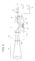
- the electronic level 1 primarily comprises an electronic level main unit 3, a sighting device (sighter) 4 to sight a target point, a base unit 5 to support the electronic level main unit 3 and to perform leveling, an ocular lens unit 6 for sighting the leveling rod 2 for electronic level at the target point, a focusing knob 7 for performing sighting the target point, a direction adjusting knob 8 for adjusting the sighting direction, an objective lens unit 9 of a telescope where a reflection light from the leveling rod 2 for the electronic level enters, an operation unit 11 where a power switch and a menu button and the like to change over a measurement mode are disposed, a display unit 12 where the present measurement mode, measurement results and the like are displayed.
- the operation unit 11 is so arranged that the operation unit 11 can change over various types of modes such as a high-speed continuous measurement mode (a crude measurement mode) to search and capture a pattern of the leveling rod 2 for electronic level by continuously carrying out the crude measurement, a precise single measurement mode for carrying out a precise measurement only once after the pattern is captured, a precise continuous measurement mode (the precise measurement mode) for continuously carrying out the precise measurement, and a precise average mode to display an average value of the precise measurement carried out as many as required as a measurement value on the display unit 12 via the menu button.
- a high-speed continuous measurement mode a crude measurement mode
- a precise single measurement mode for carrying out a precise measurement only once after the pattern is captured
- a precise continuous measurement mode (the precise measurement mode) for continuously carrying out the precise measurement
- a precise average mode to display an average value of the precise measurement carried out as many as required as a measurement value on the display unit 12 via the menu button.
- an optical system with deeper depth of field is used on the objective lens unit 9, a focusing operation is not required by using a fixed focal point or operation can be easily performed by using a mechanism, which can set a stage depending on a distance.
- a predetermined pattern e.g. a bar code 13
- marking On the leveling rod 2 for electronic level, a predetermined pattern (e.g. a bar code 13) is printed or marked (hereinafter described as "marking") on a straight base, and several types of patterns of the bar code 13 are used as patterns of the bar code to be marked on the base.
- the leveling rod 2 for electronic level may be designed as convex type where the bar code 13 is marked on a band-like base, which can be wound up.
- a first pattern A, a second pattern B and a third pattern R are repeatedly arranged with an equal distance (p). That is, one block is constituted of three types of patterns and each block is continuously formed. If it is defined that a block arranged at the lowest position is O block, and if these are marked as R(O), A(O) and B(O) respectively, these are repeatedly arranged as R(1), A(1), B(1), R(2), A(2), B(2), ⁇ . Because all patterns are repeatedly arranged at equal distance (p), by regarding a signal corresponding to the distance as a reference signal, sighting height can be acquired according to the reference signal.
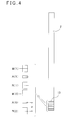
- the electronic level 1 has a sighting optical system 14, a line sensor 15, and a control arithmetic unit 16. Further, the sighting optical system 14 has the objective lens unit 9 including a focusing lens 9a, an automatic correcting unit 17, which is an automatic compensation mechanism for an optical axis, a beam splitter 18, and the ocular lens unit 6.
- the beam splitter 18 splits a reflection light from the leveling rod 2 for electronic level entering the sighting optical system 14. One of the light thus split enters the ocular lens unit 6, and the other is received by the line sensor 15.
- the control arithmetic unit 16 performs A/D conversion on the reflection light received by the line sensor 15, and reads the signal after A/D conversion and controls an uptake of the signal.
- the control arithmetic unit 16 processes the signal thus taken up, reads a pattern of the bar code 13, and calculates a height of sighting position and a distance to the leveling rod 2 for electronic level according to the size of the image of the pattern.
- the control arithmetic unit 16 has a storage unit 19 such as ROM. At the storage unit 19, parameters, data such as constant, operation expression and various types of programs such as a program for performing measurement, a program for changing over the measurement mode, etc. are stored.
- the automatic correcting unit 17 has a pair of erect prisms 21a and 21b and a mirror surface member 22, which is suspended in such manner that a reflection surface of the mirror surface member 22 is kept at horizontal position. Therefore, even when an optical axis of the sighting optical system 14 is tilted, by the gravity keeping a reflected light reflected on the horizontal mirror surface member 22, the optical axis of the reflection light projected from the erect prism 21b is maintained in horizontal direction.
- a power is turned on.
- a high-speed continuous measurement mode for automatically repeating a crude measurement is executed, and a searching of the bar code 13 is started in the high-speed continuous measurement mode.
- initial stage setting is performed such as a time interval for executing the crude measurement in the high-speed continuous measurement mode, a time interval to perform a precise measurement in a precise continuous measurement mode, how many times the precise measurement is to be performed, an exposure time of a shutter, and the like. For instance, setting is made in such manner that the precise measurement is performed at a rate of 10 times compared with the case of the crude measurement and the precise measurement is carried out at such time interval that the precise measurement is carried out more than 7 times and the measurement results are obtained.
- Step 01 After the initial setting has been completed, the electronic level main unit 3 is rotated by an operator via the base unit 5 under the condition where the crude measurement is performed. Or, the electronic level 1 is taken up and the objective lens unit 9 is directed toward the leveling rod 2 for electronic level.
- the high-speed continuous measurement is carried out at a predetermined time interval, e.g. at an interval of 0.1 second.
- the control arithmetic unit 16 monitors a signal from the line sensor 15 and judges whether or not the leveling rod 2 for electronic level has entered within a visual field of the sighting optical system 14. That is, the leveling rod 2 for electronic level is searched electronically according to a signal from the line sensor 15. The operator rotates the electronic level main unit 3, and a reflection light from the leveling rod 2 for electronic level is projected to the line sensor 15.
- a first data which is a data within capturing range including information such as a light amount of the reflection light, is acquired by processing the photodetection signal.
- Step 02 When the first data is acquired, the control arithmetic unit 16 judges whether the photodetection light amount of the first data thus acquired is adequate or not.
- the electronic level main unit 3 is continuously rotated.
- Step 03 when the light amount in the first data is judged to be adequate, the control arithmetic unit 16 judges whether the bar code 13 is present in the first data (i.e. within capturing range) or not. In a case where the bar code 13 is present in the first data even if slightly, the presence of the bar code 13 is displayed on the display unit 12. Or, by notifying via alarm, it is notified to the operator that the bar code 13 is present in the first data. The operator performs fine adjustment of horizontal angle of the electronic level main unit 3 by using the direction adjusting knob 8 or the like.
- Step 04 In Step 02, when the photodetection light amount of the first data is judged to be not adequate, the control arithmetic unit 16 calculates exposure time of a shutter based on the result of the judgment. After the result of calculation has been reflected in the setting, acquisition of the first data is carried out in Step 01 again, and the photodetection light amount is judged again in Step 02.
- Step 05 when the bar code 13 is detected in the first data, it is judged by the control arithmetic unit 16 as to whether the bar code 13 is present throughout the first data or not, that is, whether the bar code 13 is present within an effective code range W (within the range where the precise measurement can be performed).
- Step 03 when the bar code 13 is judged to be not present in the first data, the operator continues adjustment of horizontal angle of the electronic level main unit 3, and the control arithmetic unit 16 carries out a series of procedures of Step 01 to Step 03 again.
- Step 06 In Step 05, when the bar code 13 is judged to be present within the effective code range, the measurement mode is automatically changed over to the precise continuous measurement mode from the high-speed continuous measurement mode by the control arithmetic unit 16. Further, the control arithmetic unit 16 notifies the operator that the bar code 13 is present within the effective code range by displaying it on the display unit 12 or notifies by means of an alarm different from the alarm of Step 03. The operator recognizes that the bar code 13 is present within the effective code range, and fine adjustment of horizontal angle of the electronic level main unit 3 is stopped.
- a second data is acquired, which is data including information such as a light amount of the reflection light.
- Step 05 when the bar code 13 is judged to be not present within the effective code range, a series of procedures of Step 01 to Step 04 are carried out again. The operator performs fine adjustment of horizontal angle of the electronic level 1 until the bar code 13 is detected within the effective code range.
- Step 07 when the second data has been acquired, it is judged by the control arithmetic unit 16 as to whether the photodetection light amount of the second data acquired is adequate or not.
- Step 08 In Step 07, when the light amount of the second data acquired is judged to be adequate, the control arithmetic unit 16 reads a pattern of the bar code 13 and a height of sighting position is calculated, and a distance to the leveling rod 2 for electronic level is calculated from the size of the pattern image of the bar code 13.
- Step 07 when the photodetection light amount of the second data is judged to be not adequate, the control arithmetic unit 16 calculates exposure time of a shutter according to the light amount of the second data acquired in Step 06. After the result of calculation is reflected in the setting, the first data is acquired again in Step 01, and a series of the procedures in Step 02 to Step 06 is carried out again.
- Step 09 In Step 08, when the pattern of the bar code 13 is read, it is then judged whether the measurement result has been normal or not by the control arithmetic unit 16.
- Step 10 when the measurement result is judged to has been normal, it is judged by the control arithmetic unit 16 as to whether the precise measurement has been performed as many times as required in the initial setting.
- Step 09 the case where a distance or a height is judged to has not been measured correctly is as follows, for instance: a case where after the bar code 13 is detected within the effective code range in Step 05 and the measurement mode is changed over to the precise continuous measurement mode, by the fact that horizontal angle of the electronic level main unit 3 is displaced, the electronic level main unit 3 overruns and the bar code 13 goes beyond the effective code range.
- the control arithmetic unit 16 changes over again the measurement mode from the precise continuous measurement mode to the high-speed continuous measurement mode, and the first data is acquired again in Step 01, and a series of the procedures of Step 02 to Step 08 is carried out again.
- Step 11 In Step 10, when the precise measurement is judged to has been performed as many times as required, an average value of the measurement result of the precise measurement performed as many times as required is calculated by the control arithmetic unit 16, and the average value is displayed on the display unit 12 as the measured value.
- Step 10 when the precise measurement is judged to has not been performed as many times as required, a series of the procedures of Step 06 to Step 09 is repeatedly carried out until the number of the precise measurement performed reaches a required number.
- a measurement is continued until completion of the measurement is selected in the operation.
- acquisition of the second data is carried out again in Step 06, and each procedure is repeatedly performed until the completion of the measurement is selected by the operation.
- the crude measurement is started automatically.
- the operator simply directs the electronic level main unit 3 toward the leveling rod 2 for electronic level and rotates the electronic level main unit 3 in a horizontal direction
- the bar code 13 marked on the leveling rod 2 for electronic level is detected by the electronic level main unit 3, and the measurement mode is automatically changed over and the precise measurement is carried out. Therefore, there is no need that the operator manually sets up the measurement mode via the menu button of the operation unit 11 for the purpose of performing the precise measurement. This contributes to the reduction of the working load and to shorten the working time.
- the operator turns the objective lens unit 9 in a direction toward the leveling rod 2 for electronic level, and by simply rotating, the bar code 13 can be detected automatically and the precise measurement is performed.
- the operator turns the objective lens unit 9 in a direction toward the leveling rod 2 for electronic level, and by simply rotating, the bar code 13 can be detected automatically and the precise measurement is performed.
- the precise measurement can be performed automatically without the sighting operation by the operator, the measurement can be performed easily in such place where there is no additional space for working and the operator hardly goes into because of the presence of interior fittings and tools, piping, etc. in the building, and this contributes to the improvement of conveniences in the operation of the electronic level 1.
- the objective lens unit 9 is changed from a conventional optical system to an optical system with deeper depth of field, there is no need to provide auto-focusing function. This makes it possible to reduce the cost and to omit or shorten the procedure of focusing operation and the working load can be further reduced and the working time can be further shortened.
- the crude measurement is automatically started, and the precise measurement can also be automatically started by detection of the bar code 13.
- the precise measurement can also be automatically started by detection of the bar code 13.
- the sighting device 4 for performing sighting may not be used.
- the bar code 13 can be detected in an easier manner by the electronic level 1, and this contributes to further improvement of working convenience.
- FIG.7 and FIG.8 description will be given on a second embodiment of the present invention.
- the same component as in FIG.1 or FIG.5 is referred by the same symbol, and detailed description is not given here.
- an operation unit 11 and a display unit 12 are provided on an upper surface of the electronic level main unit 3 and a part of the reflection light reflected from the leveling rod 2 for electronic level (see FIG.2 ) is reflected in upward direction by a beam splitter 18, and the light enters an ocular lens unit 6.
- the electronic level 1 can be operated from above and the measurement result can be confirmed from above. Therefore, there is no need for the operator to perform operation via the operation unit 11, and also, there is no need to confirm the display unit 12 from behind the electronic level 1. This makes it possible to carry out the measurement at such place where there is no space wide enough. This contributes to further improvement of conveniences in the operation of the electronic level 1.
- the ocular lens unit 6, the operation unit 11, and the display unit 12 are provided on an upper surface of the electronic level main unit 3, while it may be so arranged that the ocular lens unit 6, the operation unit 11 and the display unit 12 are disposed on a rear surface portion of the electronic level main unit 3 similarly to the case of the first embodiment and the rear surface portion is rotatably mounted with respect to the electronic level main unit 3 so that the rear surface portion is faced in upward direction by rotating the rear surface portion.
- a laser emitting mechanism for emitting a guide laser beam in forward direction is added on the electronic level 1 and the sighting direction can be confirmed by visual inspection, and also, it may be so arranged that the operator can direct the electronic level 1 in a direction toward the leveling rod 2 of the electronic level more easily.
- a display device is separately furnished or that the display unit 12 is removably installed, and the acquired data can be transmitted to the display device or the display unit 12 via cable or radio communication so that the operator can confirm the display device or the display unit 12 while taking easier posture.
Landscapes
- Physics & Mathematics (AREA)
- Engineering & Computer Science (AREA)
- General Physics & Mathematics (AREA)
- Radar, Positioning & Navigation (AREA)
- Remote Sensing (AREA)
- Length Measuring Devices By Optical Means (AREA)
- Measurement Of Optical Distance (AREA)
Applications Claiming Priority (1)
| Application Number | Priority Date | Filing Date | Title |
|---|---|---|---|
| JP2012092989A JP2013221831A (ja) | 2012-04-16 | 2012-04-16 | 電子レベル |
Publications (1)
| Publication Number | Publication Date |
|---|---|
| EP2653831A2 true EP2653831A2 (de) | 2013-10-23 |
Family
ID=48087465
Family Applications (1)
| Application Number | Title | Priority Date | Filing Date |
|---|---|---|---|
| EP13163826.4A Withdrawn EP2653831A2 (de) | 2012-04-16 | 2013-04-15 | Elektronenniveau |
Country Status (4)
| Country | Link |
|---|---|
| US (1) | US20130269195A1 (de) |
| EP (1) | EP2653831A2 (de) |
| JP (1) | JP2013221831A (de) |
| CN (1) | CN103376091A (de) |
Families Citing this family (12)
| Publication number | Priority date | Publication date | Assignee | Title |
|---|---|---|---|---|
| JP5829848B2 (ja) | 2011-07-04 | 2015-12-09 | 株式会社トプコン | 電子レベル用標尺 |
| JP6189134B2 (ja) * | 2013-08-08 | 2017-08-30 | 株式会社トプコン | 電子レベル |
| CN104197891B (zh) * | 2014-09-05 | 2016-08-24 | 延安大学 | 水准仪目镜方向可旋转器 |
| US9354057B2 (en) | 2014-09-26 | 2016-05-31 | Trimble Navigation Limited | Electronic rod reader and field notebook |
| US9633246B2 (en) * | 2014-09-26 | 2017-04-25 | Trimble Inc. | Integrated auto-level and electronic rod reader |
| CN104949651B (zh) * | 2015-07-21 | 2017-04-19 | 爱易成技术(天津)有限公司 | 水准尺自动安平装置 |
| CN111854680A (zh) * | 2019-04-30 | 2020-10-30 | 湖南高速铁路职业技术学院 | 水准仪辅助指示测量装置 |
| JP7297636B2 (ja) * | 2019-10-25 | 2023-06-26 | 株式会社トプコン | スキャナ装置およびこれを用いた測量方法 |
| JP7335780B2 (ja) * | 2019-10-25 | 2023-08-30 | 株式会社トプコン | スキャナ装置 |
| CN111536937B (zh) * | 2020-05-22 | 2023-05-16 | 重庆工程职业技术学院 | 一种精密电子水准仪大坝变形监测系统及其监测方法 |
| CN112729233A (zh) * | 2021-01-18 | 2021-04-30 | 天津海泰建工工程质检有限公司 | 一种建筑工程检测水准仪 |
| CN113532381A (zh) * | 2021-08-05 | 2021-10-22 | 湖南旺轩科技有限公司 | 一种风塔沉降测定装置及测定方法 |
Family Cites Families (19)
| Publication number | Priority date | Publication date | Assignee | Title |
|---|---|---|---|---|
| CH676043A5 (de) * | 1983-12-30 | 1990-11-30 | Wild Leitz Ag | |
| JP2578235Y2 (ja) * | 1991-08-22 | 1998-08-06 | 株式会社ソキア | 自動視準レベル |
| US5537201A (en) * | 1993-02-16 | 1996-07-16 | Kabushiki Kaisha Topcon | Electronic leveling system, electronic leveling apparatus and leveling staff |
| JP3407143B2 (ja) * | 1993-02-16 | 2003-05-19 | 株式会社トプコン | 標尺検出機能付き電子レベル及び標尺 |
| DE19710722C2 (de) * | 1996-03-15 | 2003-06-05 | Pentax Corp | Automatische Fokussiereinrichtung für ein Fernrohr |
| JP3705889B2 (ja) * | 1997-02-07 | 2005-10-12 | 株式会社ソキア | 電子レベル |
| JPH10325718A (ja) * | 1997-05-23 | 1998-12-08 | Asahi Optical Co Ltd | 光学機器の表示装置 |
| JP3796535B2 (ja) * | 1997-10-21 | 2006-07-12 | 株式会社ソキア | 電子レベル |
| JP3789625B2 (ja) * | 1997-12-19 | 2006-06-28 | 株式会社ソキア | 電子レベル用標尺及び電子レベル |
| JP2000266540A (ja) * | 1999-03-17 | 2000-09-29 | Topcon Corp | 電子レベル |
| JP4465671B2 (ja) * | 1999-07-19 | 2010-05-19 | 株式会社トプコン | 電子式測量機 |
| JP4481673B2 (ja) * | 2004-02-10 | 2010-06-16 | Hoya株式会社 | デジタルカメラ |
| EP1619468A1 (de) * | 2004-07-22 | 2006-01-25 | Leica Geosystems AG | Geodätisches Messgerät mit Piezo-Antrieb |
| JP4648033B2 (ja) * | 2005-02-25 | 2011-03-09 | 株式会社 ソキア・トプコン | 測量機の自動焦点機構 |
| KR101128075B1 (ko) * | 2005-03-15 | 2012-07-17 | 삼성전자주식회사 | 두개의 디스플레이 패널을 갖는 디지털 촬영 장치 및 그제어 방법 |
| WO2008014813A1 (en) * | 2006-08-01 | 2008-02-07 | Trimble Jena Gmbh | Electronic leveling apparatus and method |
| CN101715542B (zh) * | 2007-05-23 | 2012-09-05 | 特里伯耶拿有限公司 | 找平设备和方法 |
| CN101666642B (zh) * | 2009-09-27 | 2011-09-28 | 常州市新瑞得仪器有限公司 | 自动测量的数字水准仪 |
| US8539685B2 (en) * | 2011-01-20 | 2013-09-24 | Trimble Navigation Limited | Integrated surveying and leveling |
-
2012
- 2012-04-16 JP JP2012092989A patent/JP2013221831A/ja active Pending
-
2013
- 2013-04-02 US US13/855,191 patent/US20130269195A1/en not_active Abandoned
- 2013-04-15 EP EP13163826.4A patent/EP2653831A2/de not_active Withdrawn
- 2013-04-16 CN CN2013101311107A patent/CN103376091A/zh active Pending
Also Published As
| Publication number | Publication date |
|---|---|
| JP2013221831A (ja) | 2013-10-28 |
| CN103376091A (zh) | 2013-10-30 |
| US20130269195A1 (en) | 2013-10-17 |
Similar Documents
| Publication | Publication Date | Title |
|---|---|---|
| EP2653831A2 (de) | Elektronenniveau | |
| US9581442B2 (en) | Surveying instrument | |
| JP5469894B2 (ja) | 測量装置及び自動追尾方法 | |
| EP3633315B1 (de) | Winkeldetektionssystem | |
| US7969586B2 (en) | Electronic leveling apparatus and method | |
| AU2009201162B8 (en) | Surveying system | |
| KR101748187B1 (ko) | 전자 레티클의 디스플레이 이미지 위치를 조정하기 위한 기능을 가지는 측정 장치 | |
| EP3211369B1 (de) | Überwachungsinstrument und programm | |
| EP2071283A2 (de) | Überwachungsinstrument | |
| US9989632B2 (en) | Measuring system, and portable radio transceiver and measurement pole used in measuring system | |
| EP3882570B1 (de) | Vermessungsinstrument und vermessungsinstrumentsystem | |
| EP2835614A1 (de) | Elektronenniveau | |
| EP1070936B1 (de) | Elektronische Nivelliereinrichtung | |
| EP2607846A2 (de) | Vermessungsgerät | |
| JP5645311B2 (ja) | 光波距離計 | |
| JP3816812B2 (ja) | トータルステーション | |
| JP5313595B2 (ja) | 電子レベル | |
| JP2006234614A (ja) | 測量機の自動焦点機構 | |
| JP5031652B2 (ja) | 測量機の自動焦点制御装置 | |
| JP2001174260A (ja) | 測量機及び測量方法 | |
| JP2021067613A (ja) | スキャナ装置およびこれを用いた測量方法 |
Legal Events
| Date | Code | Title | Description |
|---|---|---|---|
| PUAI | Public reference made under article 153(3) epc to a published international application that has entered the european phase |
Free format text: ORIGINAL CODE: 0009012 |
|
| AK | Designated contracting states |
Kind code of ref document: A2 Designated state(s): AL AT BE BG CH CY CZ DE DK EE ES FI FR GB GR HR HU IE IS IT LI LT LU LV MC MK MT NL NO PL PT RO RS SE SI SK SM TR |
|
| AX | Request for extension of the european patent |
Extension state: BA ME |
|
| STAA | Information on the status of an ep patent application or granted ep patent |
Free format text: STATUS: THE APPLICATION HAS BEEN WITHDRAWN |
|
| 18W | Application withdrawn |
Effective date: 20160317 |