EP2652219B1 - Wall assembly - Google Patents
Wall assembly Download PDFInfo
- Publication number
- EP2652219B1 EP2652219B1 EP11813349.5A EP11813349A EP2652219B1 EP 2652219 B1 EP2652219 B1 EP 2652219B1 EP 11813349 A EP11813349 A EP 11813349A EP 2652219 B1 EP2652219 B1 EP 2652219B1
- Authority
- EP
- European Patent Office
- Prior art keywords
- beams
- positioning
- wall
- wall assembly
- profile
- Prior art date
- Legal status (The legal status is an assumption and is not a legal conclusion. Google has not performed a legal analysis and makes no representation as to the accuracy of the status listed.)
- Active
Links
Images



Classifications
-
- E—FIXED CONSTRUCTIONS
- E04—BUILDING
- E04B—GENERAL BUILDING CONSTRUCTIONS; WALLS, e.g. PARTITIONS; ROOFS; FLOORS; CEILINGS; INSULATION OR OTHER PROTECTION OF BUILDINGS
- E04B2/00—Walls, e.g. partitions, for buildings; Wall construction with regard to insulation; Connections specially adapted to walls
- E04B2/02—Walls, e.g. partitions, for buildings; Wall construction with regard to insulation; Connections specially adapted to walls built-up from layers of building elements
- E04B2/04—Walls having neither cavities between, nor in, the solid elements
- E04B2/06—Walls having neither cavities between, nor in, the solid elements using elements having specially-designed means for stabilising the position
- E04B2/08—Walls having neither cavities between, nor in, the solid elements using elements having specially-designed means for stabilising the position by interlocking of projections or inserts with indentations, e.g. of tongues, grooves, dovetails
-
- E—FIXED CONSTRUCTIONS
- E04—BUILDING
- E04B—GENERAL BUILDING CONSTRUCTIONS; WALLS, e.g. PARTITIONS; ROOFS; FLOORS; CEILINGS; INSULATION OR OTHER PROTECTION OF BUILDINGS
- E04B2/00—Walls, e.g. partitions, for buildings; Wall construction with regard to insulation; Connections specially adapted to walls
- E04B2/56—Load-bearing walls of framework or pillarwork; Walls incorporating load-bearing elongated members
- E04B2/70—Load-bearing walls of framework or pillarwork; Walls incorporating load-bearing elongated members with elongated members of wood
- E04B2/701—Load-bearing walls of framework or pillarwork; Walls incorporating load-bearing elongated members with elongated members of wood with integrated supporting and obturation function
- E04B2/705—Load-bearing walls of framework or pillarwork; Walls incorporating load-bearing elongated members with elongated members of wood with integrated supporting and obturation function with longitudinal horizontal elements placed between columns
-
- E—FIXED CONSTRUCTIONS
- E04—BUILDING
- E04H—BUILDINGS OR LIKE STRUCTURES FOR PARTICULAR PURPOSES; SWIMMING OR SPLASH BATHS OR POOLS; MASTS; FENCING; TENTS OR CANOPIES, IN GENERAL
- E04H1/00—Buildings or groups of buildings for dwelling or office purposes; General layout, e.g. modular co-ordination or staggered storeys
- E04H1/12—Small buildings or other erections for limited occupation, erected in the open air or arranged in buildings, e.g. kiosks, waiting shelters for bus stops or for filling stations, roofs for railway platforms, watchmen's huts or dressing cubicles
- E04H1/125—Small buildings, arranged in other buildings
-
- E—FIXED CONSTRUCTIONS
- E04—BUILDING
- E04H—BUILDINGS OR LIKE STRUCTURES FOR PARTICULAR PURPOSES; SWIMMING OR SPLASH BATHS OR POOLS; MASTS; FENCING; TENTS OR CANOPIES, IN GENERAL
- E04H1/00—Buildings or groups of buildings for dwelling or office purposes; General layout, e.g. modular co-ordination or staggered storeys
- E04H1/12—Small buildings or other erections for limited occupation, erected in the open air or arranged in buildings, e.g. kiosks, waiting shelters for bus stops or for filling stations, roofs for railway platforms, watchmen's huts or dressing cubicles
- E04H2001/1288—Sauna cabins
Definitions
- This invention concerns a wall assembly for the construction of a wall element, comprising:
- Such wall assemblies most often are part of structures that are constructed from massive timber construction.
- massive timber construction is a building method in which wooden beams are stacked on each other to produce a structure such as a building.
- These structures can be, for example, scenerys, saunas, weekend houses, houses, summer houses, swimming pools, fences, caravans, and so on.
- profile is meant an elongated element having substantially the same cross section over its length.
- a known problem with massive timber construction is that by expansion and shrinkage of the beams a wall assembly of approximately 2 metres height can sink by as much as 3 cm over the course of time, due to the cumulative height shrinkage of the beams stacked on each other.
- a sauna cabin can even sink by as much as 5 cm along its height.
- a major drawback here is that doors and windows can become heavily loaded by beams that are stacked on them and no longer supported by underlying beams. These doors and windows can become warped or can no longer be opened or closed under this load.
- a further drawback is that it is not expected of the working of a building etc. that a wall assembly can settle by as much as 3 cm.
- AU 2010 200 477 A1 discloses a wall assembly comprising all of the features of the preamble of claim 1.
- the purpose of this invention is to provide a connection system whereby the aforementioned problem is remedied.
- the purpose is therefore substantially to provide a solution that neutralizes the natural dimensional variations due to shrinkage and/or expansion in such a wall assembly.
- a wall assembly for the construction of a wall element comprising:
- the positioning elements Thanks to the positioning elements, the height differences for every beam are prevented from accumulating in the event of expansion or shrinkage of the beams, so that large height differences for every wall element no longer occur.
- the beams can indeed shrink or expand in themselves, without departing from their initially assigned positioning.
- Positioning elements that do not extend over the complete length between the profiles, but only extend substantially between positioning ends of the beams, can be secured to the profile from its side against which the beams extend in the mounted state of the wall element, so that extra installation space in the prolongation of the wall element is no longer required to be able to mount this wall element.
- Each positioning element is therefore preferably configured so as to be able to be fastened to a profile from the side of the profile against which the beams extend in the mounted state of the wall element.
- the positioning elements in the mounted state of the wall element extend only between the respective positioning ends of the two beams stacked one on top of the other, so that the beams can adjoin each other as tightly as possible when stacked on each other.
- the height of these positioning elements is then preferably smaller than or equal to the net construction height of a beam, minus the height of its positioning end.
- the positioning elements of such a wall assembly are preferably rigid.
- each profile in a preferred embodiment of a wall assembly according to this invention is provided with a slot, in which the respective positioning ends of the beams can be at least partly disposed and in which the positioning elements can be at least partly disposed.
- each profile is provided at least at one end with an entry opening to the aforesaid slot, by which the positioning ends and the positioning elements can be at least partly arranged in this slot.
- the positioning ends and the positioning elements can be at least partly arranged in this slot.
- the cross section of the positioning ends is preferably complementary to the cross section of the slot.
- complementary is meant that the cross section of the positioning ends and the cross section of the slot are matched to each other, so that the cross section of the positioning ends is somewhat smaller than the cross section of the slot and can be fully taken up in it.
- the cross section of the positioning elements is preferably complementary to the cross section of the slot.
- complementary is meant that the cross section of the positioning elements and the cross section of the slot are matched to each other, so that the cross section of the positioning elements is somewhat smaller than the cross section of the slot and can be fully taken up in it.
- each profile is provided with flanges that partly bound the aforesaid slot, so that they delimit a through opening to this slot.
- Each positioning end is then preferably configured at least in part broader than the width of the through opening, in which case the profile then comprises an aforesaid entry opening so that this positioning end cannot be moved in and out of the slot through this through opening, but only via the aforementioned entry opening.
- each positioning element in such a specific embodiment is preferably configured so that it can be secured to an aforementioned profile by clamping it against these flanges.
- Each positioning end in such a specific embodiment is then preferably provided with a narrowing that has a width that is smaller than or equal to the width of the aforesaid through opening.
- At least one profile comprises a second slot, for attachment of two or more beams that are part of a second wall element.
- the second slot in yet another particular embodiment is located at an angle with respect to the first-mentioned slot, so that the second wall element in the mounted state of the wall assembly extends at an angle with respect to the first-mentioned wall element.
- the profiles can then be provided with several slots for attachment of several wall elements to the same profile, which can be located at different angles with respect to each other, corresponding to the angles of the slots with respect to each other.
- the beams of a wall assembly according to this invention are preferably made of wood. Moreover, these beams are preferably each provided with at least one tongue and at least one groove, so that these beams can be stacked on each other by means of a tongue and groove connection.
- the height of these tongues and grooves is preferably chosen such that after shrinkage of the beams there still remains a sufficient overlap of the tongues and grooves so that no cracks occur between the beams.
- the profiles of a wall assembly according to this invention are preferably made of metal. More specifically, these profiles can be aluminium profiles, for example, that are made by means of extrusion. For aluminium has a negligible shrinkage and expansion, and suitable surface smoothness, rigidity and strength for the application. Furthermore, no rusting occurs with aluminium, it is user-friendly and fully recyclable.
- the positioning elements of a wall assembly according to this invention are preferably made of polypropylene. These could also be made from another plastic, such as PVC, or of aluminium, etc.
- the purpose of this invention is likewise achieved by providing a wall element that is constructed from a wall assembly according to the invention as described above.
- a wall element that is constructed from a wall assembly according to the invention as described above.
- Such wall elements can be incorporated in structures such as summer houses, swimming pools, saunas, fences, houses, caravans, etc.
- the purpose of this invention is furthermore also more specifically achieved by providing a sauna cabin that comprises a wall assembly according to this invention as described above.
- a wall assembly (1) according to this invention is intended for the building of wall elements (14, 15) that can be incorporated in all kinds of structures made of massive timber construction. These structures can be, for example, summer houses, swimming pools, saunas, fences, houses, caravans, etc.
- Such a wall assembly (1) always comprises at least two profiles (3) which in the mounted state of the wall element (14) extend substantially vertically as ends of the wall element (14).
- part of such a wall element (14) is shown in top view at the height of one of these profiles (3).
- one end of a first and a second wall element (14, 15) are shown in perspective view, which join each other at an angle with a joint angle profile (3).
- the profiles (3) depicted are extruded metal profiles. Such extruded aluminium profiles that are currently available on the market are only suited to connection with other metal elements.
- the slots are narrower and less deep. In order to be able to make use of them as extruded profiles (3) for a wall assembly (1) according to the invention with wooden beams (2), the slots (8) need to be deep and broad enough. Depending on the application, these profiles (3) could also be manufactured from plastic, for example. It is also possible to make profiles for a wall assembly according to this invention from wood, for example, in which case one needs to take account of the material strength and the risk of splitting of this wood for a particular tensile strength and when using fastening elements to attach elements to these profiles (3).
- beams (2) that are stacked on each other extend substantially horizontally between these profiles (3).
- These beams (2) can be made from massive timber with the known techniques. For alternative applications, these could also be made, for example, from composite material or laminated wood, or plastic etc.
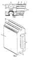
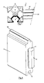
- FIGS 2 and 8 one end of such a beam (2) is shown separately in perspective view.
- the beams (2) comprise at each end a positioning end (6).
- This positioning end (6) has a height less than the height of the respective beam (2).
- the width of this positioning end (6) is also narrower than the width of the beam (2).
- Such a positioning end (6) can therefore be fabricated by four-sided crosscut milling of the corresponding end of the corresponding beam (2).
- the beams (2) of the first embodiment of a wall assembly (1) as depicted in Fig. 2 are provided on their top side with two tongues (10) and on their bottom side with two grooves (11).
- the beams (2) of the second embodiment of a wall assembly (1) as depicted in Fig. 8 are provided on their top side with one tongue (10) and on their bottom side with one groove (11). Thanks to these tongues (10) and grooves (11), these beams (2) can be stacked on each other with the help of a tongue and groove connection.
- the number of tongues (10) and the number of grooves (11) is preferably chosen as a function of the desired tongue and groove connection and as a function of the thickness of the beams (2).
- the height of the tongues (10) and grooves (11) is chosen such that when the height of the beams (2) in the wall element (14, 15) is fixed according to this invention, even upon shrinkage of the beams (2) an overlap will always remain between the tongues (10) and the grooves (11), so that no cracks occur between the beams (2).
- the beams (2) of the depicted embodiments are moreover symmetrical in construction, so that when these beams are mounted in a wall assembly (1) one can choose which flat side to turn inward or outward.
- a wall assembly (1) also comprises two positioning elements (4) for every two beams (2) to be stacked on one another.
- Such positioning elements (4) are also shown separately in Figures 3, 5 , 9 and 11 .
- These positioning elements (4) can be fastened to the profiles (3), each at a respective end of the beams (2), so that these positioning elements (4) in the mounted state of the wall element (14) are located between the positioning ends (6) of these two stacked beams (2) and the upper one of these stacked beams (2) is supported on these positioning elements (4) by its positioning ends (6).
- the depicted positioning elements (4) are made of polypropylene. However, it is also possible to make such positioning elements (4) from another plastic, or from metal etc.
- the material used is preferably sufficiently firm so that, after fastening of these positioning elements (4) to the profiles (3), the respective beams (2) can be supported by means of these positioning elements (4).
- the positioning elements (4) are provided with a borehole for fastening of a socket set screw (5), which is shown separately in Figs. 4 and 10 . With the help of such a socket set screw (5), such a positioning element (4) can then be fastened to a profile (3).
- the depicted profiles (3) each comprise four slots (8), in which the positioning elements (4) and the positioning ends (6) of the beams (2) can be arranged.
- the profiles (3) are provided on their top side with entry openings (12) to these slots (8), by which the positioning elements (4) and the positioning ends (6) can be arranged in the slots (8).
- Each profile (3) moreover, is provided with flanges (9) that partly border on the slots (8), so that they delimit at least partly a through opening (13) to this slot (8).
- the positioning elements (4) in such embodiments can be arranged so that they are removed from view in the mounted state of the wall assembly (1). These positioning elements (4) furthermore fill up the opening between positioning ends (6) of stacked beams (2) as much as possible, so that the connection becomes water and wind-tight and energy losses are limited.
- the cross sections of both the positioning elements (4) and the positioning ends (6) of the beams (2) in the various depicted embodiments of wall assemblies (1) are each time fashioned to be as complementary as possible to the cross section of the corresponding slots (8), to enable a maximum supporting of the beams (2).
- the positioning ends (6) are provided with a narrowing (7).
- This narrowing (7) has a width that is less than or equal to the width of the through opening (13), so that the beams (2) can be arranged in the slots (8) with the help of these positioning ends (6).
- the width of that part of the positioning ends (6) that can be arranged in the slots (8) themselves is broader than the width of the through opening (13).
- the slots (8) in the second embodiment are designed so that a wall assembly (1) according to this second embodiment can handle greater lateral tensile forces than a wall assembly (1) with the slots (8) from the first embodiment.
- a positioning element (4) When building a wall element (14, 15) with these depicted wall assemblies (1), one first arranges a positioning element (4) in the desired slots (8) of the profiles (3) in which beams (2) are to be arranged. After this, a beam (2) is arranged between two profiles (3) by arranging it with the help of its positioning ends (6) in the slots (8) of these profiles (3) via the entry openings (12). Then on top of each positioning end (6) a positioning element (4) is placed in the corresponding slot (8) via the corresponding positioning opening (12). These positioning elements (4) are fixed at the desired height by tightening the socket set screws (5) until the positioning elements (4) are drawn tight against the flanges (9). As is clearly shown in Figs.
- the socket set screws (5) can be reached for this purpose from the side of the profile (3) against which the beams (2) extend, so that no surrounding space is needed in the prolongation of the wall elements (14, 15) in order to mount them.
- the socket set screws (5) are tightened against the core of the respective profile (3) in order to tighten the positioning elements (4) against the flanges (9).
- a second beam (2) is placed between the profiles (3). This second beam (2) is stacked on the first beam (2) so that it is supported by the positioning elements (4) that were fixed at the desired height on top of this first beam (2).
- positioning elements (4) are again fixed on top of the positioning ends (6) of this second beam (2) at the desired height in the slots (8) against the flanges (9) in order to support a third beam (2) that will be stacked on the second beam (2). Then, in succession, positioning elements (4) and beams (2) are put in place until the complete wall element (14, 15) has been raised.
- the beams (2) of the depicted wall assemblies (1) each time have coinciding dimensions.
- the positioning elements (4) in this case have a height that coincides with the net construction height of a beam (2), minus the height of its positioning end (6), so that all elements of the wall assembly (1) can initially join to each other in order to produce a firm unit that remains a firm unit even upon shrinkage and/or expansion of the beams (2).
- the profiles (3) depicted in Figs. 1 , 6 , 7 and 12-14 each time have four slots (8) in which beams (2) can be arranged at perpendicular angles to each other, in order to construct wall elements (14, 15) that extend at right angles to each other.
- wall assemblies (1) according to this invention can equally well comprise profiles (3) with more or fewer slots (8), where the angle at which different slots (8) are placed relative to each other in the profiles (3) can also differ from a right angle.
- Figs. 15 to 18 a number of additional possible profiles (3) are depicted. It is of course possible to think of countless variants of the embodiments depicted. Already with the wall assemblies (1) depicted, a great diversity of structures can be built. A further diversity in structures can be achieved by using or not using the slots (8) provided. Thus, for example, one can provide unused slots (8), in order to be able to use these later on to build an addition. The positioning and the number of slots (8) is preferably chosen as a function of the desired construction that needs to be built with such a wall assembly (1).
- a profile (3) of the embodiment depicted in Fig. 17 two slots (8) are provided at an angle of 135° relative to each other, so that beams (2) which are fastened to them can join each other at such an angle. In this way, it is also possible to realize octagonal structures, for example.
- a profile (3) can be configured with slots (8) that are provided at an angle of 120° relative to each other, so that hexagonal structures can be realized with them.
- one slot (8) is provided in the profile (3) of the embodiment depicted in Fig. 18 . Between such profiles (3) one can make a connection with doors and/or windows, for example.
- a through recess (16) is provided at the centre, with small raised edges at the margin.
- an M8 screw thread for example, which can be adjustable in height, or adjoining profiles (3) can be attached, and so on, as is already known for such profiles in metal structures.
- the additional cavities (17) that are present in these profiles (3) can be used to take up wiring, for example, as is also already known for such profiles in metal structures.
Landscapes
- Engineering & Computer Science (AREA)
- Architecture (AREA)
- Civil Engineering (AREA)
- Structural Engineering (AREA)
- Physics & Mathematics (AREA)
- Electromagnetism (AREA)
- Joining Of Building Structures In Genera (AREA)
- Finishing Walls (AREA)
- Conveying And Assembling Of Building Elements In Situ (AREA)
Priority Applications (1)
| Application Number | Priority Date | Filing Date | Title |
|---|---|---|---|
| PL11813349T PL2652219T3 (pl) | 2010-12-16 | 2011-12-09 | Ścienny zespół |
Applications Claiming Priority (2)
| Application Number | Priority Date | Filing Date | Title |
|---|---|---|---|
| BE2010/0744A BE1019706A3 (nl) | 2010-12-16 | 2010-12-16 | Wandsamenstel. |
| PCT/IB2011/002979 WO2012080801A1 (en) | 2010-12-16 | 2011-12-09 | Wall assembly |
Publications (2)
| Publication Number | Publication Date |
|---|---|
| EP2652219A1 EP2652219A1 (en) | 2013-10-23 |
| EP2652219B1 true EP2652219B1 (en) | 2014-10-08 |
Family
ID=44281066
Family Applications (1)
| Application Number | Title | Priority Date | Filing Date |
|---|---|---|---|
| EP11813349.5A Active EP2652219B1 (en) | 2010-12-16 | 2011-12-09 | Wall assembly |
Country Status (9)
| Country | Link |
|---|---|
| US (1) | US8789325B2 (pl) |
| EP (1) | EP2652219B1 (pl) |
| AU (1) | AU2011342940B2 (pl) |
| BE (1) | BE1019706A3 (pl) |
| CA (1) | CA2816951C (pl) |
| DK (1) | DK2652219T3 (pl) |
| ES (1) | ES2523937T3 (pl) |
| PL (1) | PL2652219T3 (pl) |
| WO (1) | WO2012080801A1 (pl) |
Cited By (2)
| Publication number | Priority date | Publication date | Assignee | Title |
|---|---|---|---|---|
| RU168795U1 (ru) * | 2016-08-02 | 2017-02-21 | Андрей Анатольевич Колесников | Угловое соединение "двойной брус - ласточкин хвост" |
| NO20160409A1 (no) * | 2016-03-10 | 2017-09-11 | Riska Sagbruk As | Plank for bruk i en vegg i en bygning, en fremgangsmåte for utforming av samme og et byggesystem som omfatter planken. |
Families Citing this family (30)
| Publication number | Priority date | Publication date | Assignee | Title |
|---|---|---|---|---|
| USD720608S1 (en) * | 2013-01-22 | 2015-01-06 | Toyoda Products Co., Ltd. | Pipe connector for furniture kits |
| KR101353546B1 (ko) * | 2013-04-12 | 2014-01-22 | 박창은 | 목재벽돌조립체 |
| US9234349B1 (en) | 2013-08-30 | 2016-01-12 | Convergent Market Research, Inc. | Concrete panel system and method for forming reinforced concrete building components |
| US9879413B2 (en) * | 2014-02-13 | 2018-01-30 | Settimio CASTELLI | Modular structural system |
| US9797149B2 (en) * | 2014-07-09 | 2017-10-24 | Western Timber Frame, Inc. | Timber frame structures with improved joint assemblies |
| ITUB20153496A1 (it) * | 2015-09-09 | 2017-03-09 | Univ Degli Studi G Dannunzio Chieti Pescara | Sistema costruttivo ad ossatura portante in calcestruzzo armato o in acciaio integrato con pannelli di tamponatura in legno. |
| US20170121958A1 (en) * | 2015-11-01 | 2017-05-04 | Youxuan Jin | Construction Method to Reinforce Masonry Walls with Wood |
| MX2018007957A (es) * | 2015-12-29 | 2018-11-09 | Convergent Market Res Inc | Sistema de panel de concreto y metodo para la formacion de componente de construccion de concreto reforzado. |
| US10058789B2 (en) * | 2016-01-12 | 2018-08-28 | Creative Styles LLC | Modular play structure system |
| US20170211272A1 (en) * | 2016-01-22 | 2017-07-27 | Cityscapes International, Inc. | Modular containment and screening system |
| CN110893610A (zh) | 2016-05-02 | 2020-03-20 | 凯特尔塑料有限公司 | 实用组件和联接机构 |
| US9995327B2 (en) * | 2016-06-01 | 2018-06-12 | Charles D. Hudson | Connector and building system |
| DE102017121970A1 (de) * | 2016-09-23 | 2018-03-29 | Marco Rutzke | Individuelle Raumeinheit gebildet aus Eckeinheiten und Arbeitsplatzumgebung unter Verwendung der Raumeinheit und weitere Verwendung der Raumeinheit |
| US10858822B2 (en) * | 2016-11-30 | 2020-12-08 | Iida Sangyo Co., Ltd. | Construction and method for constructing same |
| US10441077B2 (en) * | 2016-12-14 | 2019-10-15 | Sizable Enterprises Incorporated | Compartment divider assembly |
| US9839289B1 (en) | 2016-12-14 | 2017-12-12 | Sizable Enterprises Incorporated | Compartment divider assembly |
| CH714202A1 (fr) * | 2017-09-29 | 2019-03-29 | Ustinov Igor | Système de construction pour un module d'un bâtiment. |
| EA034682B1 (ru) * | 2018-07-20 | 2020-03-05 | Юсупова, Елена Георгиевна | Модульная строительная система |
| WO2020065125A1 (en) * | 2018-09-25 | 2020-04-02 | Block Solutions Oy | Method and module system for building a wall structure |
| US10844606B2 (en) | 2018-10-10 | 2020-11-24 | Bradley Jay Lavery | Timber frame structure with arched roof |
| US11084245B2 (en) * | 2019-01-09 | 2021-08-10 | Six Minutes LLC | Cross-laminated timber having a conduit therein |
| GB202001437D0 (en) * | 2020-02-03 | 2020-03-18 | Dvlp Int Ltd | Building system |
| US11578489B2 (en) * | 2020-08-19 | 2023-02-14 | Gary Fickling | Solid wood wall system |
| JP7467007B2 (ja) * | 2020-09-28 | 2024-04-15 | 日軽パネルシステム株式会社 | ブース及びブースの構築方法 |
| MX2023005554A (es) * | 2020-11-11 | 2023-05-29 | Buildz Llc | Conectores para montar unidades de construccion modulares. |
| AT525131B1 (de) * | 2021-05-27 | 2025-02-15 | Josef Priglinger | Modulares Hochbeetsystem |
| IT202100024188A1 (it) * | 2021-09-21 | 2023-03-21 | Starpool S R L | Cabina per trattamenti benessere, particolarmente bagni turchi e simili |
| US12297642B1 (en) * | 2021-10-11 | 2025-05-13 | Truly Modular Systems | Modular interlocking assembly system |
| US12326006B2 (en) * | 2022-10-14 | 2025-06-10 | The Superior Sauna Company, LLC | Prefabricated/modular sauna |
| US20250223793A1 (en) * | 2024-01-06 | 2025-07-10 | Timothy S Searle | Metrideck Rapid Deployment and Reconfigurable Structural System for temporary or semi-permanent buildings such as trade show displays, corporate lobbies, or Museum Displays |
Family Cites Families (83)
| Publication number | Priority date | Publication date | Assignee | Title |
|---|---|---|---|---|
| US1898297A (en) * | 1931-09-23 | 1933-02-21 | Fox Ned Barcley | Building blocks |
| US2059565A (en) * | 1931-11-10 | 1936-11-03 | Partitions Inc | Metal partition |
| US2414060A (en) * | 1943-12-08 | 1947-01-07 | Anchorage Homes Inc | Interlocking wedge joint for securing together prefabricated building panels |
| US2453221A (en) * | 1944-07-21 | 1948-11-09 | Emile S Guignon Jr | Interlocking building units |
| US2930222A (en) * | 1955-11-14 | 1960-03-29 | Robert D Bender | Prefabricated interlocking structural slabs |
| US3026977A (en) * | 1958-03-13 | 1962-03-27 | Hauserman Co E F | Panel assembly |
| US3251169A (en) * | 1960-11-07 | 1966-05-17 | Arnold J Cornelissen | Modular construction system |
| US3178775A (en) * | 1962-11-14 | 1965-04-20 | Tassell Hardware Company | Demountable wall and mounting fixture therefor |
| US3371454A (en) * | 1965-10-24 | 1968-03-05 | Anderson Mfg Co V E | Partition structure |
| US3490800A (en) * | 1967-06-01 | 1970-01-20 | Ray F Wissler | Beam and lock strip |
| US3566561A (en) * | 1968-10-08 | 1971-03-02 | Francis P Tozer | Channelled structural elements |
| US3600867A (en) * | 1969-10-16 | 1971-08-24 | Bernice W Shuey | Building block construction and assemblage |
| US3849960A (en) * | 1971-05-24 | 1974-11-26 | M Larimer | Modular building construction |
| AU526070B2 (en) * | 1978-12-08 | 1982-12-16 | Fletcher Timber Ltd. | Building system |
| US4599837A (en) * | 1981-06-01 | 1986-07-15 | Wrightman Ronald A | Log joining configuration |
| DE3203684A1 (de) * | 1982-02-04 | 1983-08-11 | Gerhard 2106 Bendestorf Post | Blockhaus |
| FR2556022B1 (fr) * | 1983-12-06 | 1986-09-12 | Chupin Michel | Perfectionnement aux parois en planches de bois |
| US4742657A (en) * | 1984-10-26 | 1988-05-10 | Veech Robert D | Wall structure and method of making |
| US4867598A (en) * | 1987-10-16 | 1989-09-19 | Winter Amos G Iv | Tapered dovetail mortise and tenon joint structure |
| DE3804525A1 (de) | 1988-02-13 | 1989-08-24 | Wolfgang Schreiber | Saunawand aus blockbohlen |
| US5244300A (en) * | 1991-02-28 | 1993-09-14 | Lehigh University | Structural connector approximating a cone of elliptical cross-section |
| US5361556A (en) * | 1993-02-25 | 1994-11-08 | National Gypsum Company | Horizontal unitized panel |
| US5577356A (en) * | 1994-03-25 | 1996-11-26 | Panabode Cedar Homes, Inc. | Pre-cut building method and structure |
| JPH08128420A (ja) * | 1994-10-31 | 1996-05-21 | N I Shi Auto Tec Kk | 連結材 |
| GB2297336B (en) * | 1995-01-28 | 1997-04-16 | Brian Harry Kelly | Junction members and their uses |
| EP0863714B1 (en) * | 1995-11-28 | 2002-07-24 | Systems Supply Pty. Ltd. | Tile panel system |
| CA2171355A1 (en) * | 1996-03-08 | 1997-09-09 | Paul Thomas Maddock | Toy construction kit with interconnecting building pieces |
| TW329446B (en) * | 1996-04-29 | 1998-04-11 | Syma Intercontinental Sa | Profiled beam and clamping profile for profiled beams |
| DE29612106U1 (de) * | 1996-07-11 | 1996-09-12 | Knürr-Mechanik für die Elektronik AG, 81829 München | Tragsystem für Arbeitsmöbel |
| US5682719A (en) * | 1996-07-15 | 1997-11-04 | Huang; Chin-Fa | Screen combination |
| US5890332A (en) * | 1997-01-17 | 1999-04-06 | Skidmore; Lester J. | Reconstituted wood block modular building system |
| US6094876A (en) * | 1997-03-21 | 2000-08-01 | Ogo; Tatsujiro | Corner construction for buildings having stacked tongue-and-groove lumber or log construction or the like |
| US5921046A (en) * | 1997-04-04 | 1999-07-13 | Recobond, Inc. | Prefabricated building system for walls, roofs, and floors using a foam core building panel and connectors |
| US5799452A (en) * | 1997-06-11 | 1998-09-01 | Moore; Kenneth G. | Log construction |
| DE19739787C2 (de) | 1997-09-10 | 1999-09-02 | Klafs Saunabau | Blockbohlen-Sauna |
| NL1007399C2 (nl) * | 1997-10-30 | 1999-05-10 | Withagen Theodorus Adrianus Joh | Samenstel voor het opbouwen van een wand en/of gebouw en werkwijze gebruikmakend daarvan. |
| US5918999A (en) * | 1998-03-27 | 1999-07-06 | Lamarca; Guy M. | Geometric spacial frame assembly |
| US6189282B1 (en) * | 1998-06-24 | 2001-02-20 | Building Works, Inc. | Mortarless concrete block |
| DE19841359C1 (de) | 1998-09-10 | 1999-11-11 | Teka Saunabau Gmbh | Saunakabine aus flächigen Elementen |
| HN1998000160A (es) * | 1998-10-09 | 1999-01-08 | Karl Herman Berberich | Sistema constructivo modular hondulog |
| DE29920656U1 (de) * | 1999-11-24 | 2000-02-17 | Vincent, Irvin G., Luxemburg, Wis. | Universelles Bauelement |
| US6568143B2 (en) * | 2000-06-23 | 2003-05-27 | Withrow Block, L.L.C. | Interlocking construction components |
| US6493995B2 (en) * | 2000-08-21 | 2002-12-17 | Mckenzie Alexander L. | Modular exhibit panel and locking system |
| CA2316569A1 (en) * | 2000-08-21 | 2002-02-21 | Vladimir Perett | Portable sauna |
| US20030019170A1 (en) * | 2001-07-27 | 2003-01-30 | Donnelly Thomas F. | Sound barrier wall system |
| US6837016B2 (en) * | 2001-08-30 | 2005-01-04 | Simmons Robert J | Moment-resistant building frame structure componentry and method |
| US6931803B1 (en) * | 2002-03-08 | 2005-08-23 | Gary Davis | Modular building system |
| NL1022100C2 (nl) * | 2002-12-06 | 2004-06-08 | Rouweler Groep B V | Wandelement, tuinconstructie, werkwijze voor het opbouwen van een bouwelement, staander en bouwpakket. |
| US7108577B2 (en) * | 2002-12-24 | 2006-09-19 | Peters Andrew J | Wedge-lock building blocks |
| US7117647B2 (en) * | 2003-02-26 | 2006-10-10 | Pointblank Design Inc. | System for constructing log structures |
| US20070294967A1 (en) * | 2003-03-11 | 2007-12-27 | Klaus Posselt | System of interlocking wall and corner components for construction of buildings |
| CA2459946A1 (en) * | 2003-03-11 | 2004-09-11 | Klaus Posselt | System of interlocking wall and corner components for construction of buildings |
| US20040255531A1 (en) * | 2003-06-19 | 2004-12-23 | Middleton Jeff C. | System for finishing openings in log structures |
| CN1601023A (zh) * | 2003-09-23 | 2005-03-30 | 汪荣勋 | 用于形成墙体的砌块及其形成的墙体以及砌块的用途 |
| NO320956B1 (no) * | 2004-03-26 | 2006-02-20 | Isolaft As | Endestykke for bruk ved lafting. |
| US7845266B2 (en) * | 2004-07-14 | 2010-12-07 | Ballistics Blocks Llc | Modular polymeric projectile absorbing armor |
| US7806038B2 (en) * | 2004-07-14 | 2010-10-05 | Duke Leslie P | Modular polymeric projectile absorbing armor |
| US20060179768A1 (en) * | 2005-02-04 | 2006-08-17 | Lindeen Steve V | Panel wall system, parts thereof and method of installation |
| US20070006539A1 (en) * | 2005-07-08 | 2007-01-11 | Russell Gurstein | Log Construction Flexible Seal Gasket |
| CN101292071A (zh) * | 2005-09-06 | 2008-10-22 | 爱克斯博兰责任有限公司 | 用于建造墙壁的建筑系统 |
| US7597771B2 (en) * | 2006-02-07 | 2009-10-06 | Comfort Line Ltd. | Pultrusion method and related article |
| US20070245638A1 (en) * | 2006-03-29 | 2007-10-25 | Chang-Cheng Lai | On a sauna structure |
| DE202006011008U1 (de) | 2006-07-17 | 2006-10-05 | Tor Tec Gmbh | Freitragendes Schiebetor |
| US8171683B2 (en) * | 2006-08-28 | 2012-05-08 | Wrightman Robert A | Log for log home |
| FR2907478B1 (fr) * | 2006-10-20 | 2017-04-28 | Agri Scierie Mobile | Nouvel assemblage de profiles en bois ou en materiau de synthese au moyen de pieces de jonction metalliques |
| DE202006018839U1 (de) * | 2006-12-04 | 2007-02-22 | Octanorm-Vertriebs-GmbH für Bauelemente | System zum Erstellen von Aufbauten und Tragprofil |
| US20080134599A1 (en) * | 2006-12-08 | 2008-06-12 | Raymond Ward Downing | Swedge interlok system |
| US8371080B2 (en) * | 2007-08-28 | 2013-02-12 | Robert A. Wrightman | Log wall connector system |
| US20090199497A1 (en) * | 2007-08-28 | 2009-08-13 | Wrightman Robert A | Log wall connector system |
| US8615963B2 (en) * | 2007-08-28 | 2013-12-31 | Robert A. Wrightman | Log wall connector system |
| US9091059B2 (en) * | 2007-09-13 | 2015-07-28 | Robert A. Wrightman | Log building |
| AU2008307933A1 (en) * | 2007-10-05 | 2009-04-09 | Hankook Styropol Co., Ltd | Constructive light weight insulation block and construction method thereof |
| US20100043323A1 (en) * | 2008-06-25 | 2010-02-25 | Wrightman Ronald A | Insulated log homes |
| US8567139B2 (en) * | 2008-10-14 | 2013-10-29 | Alejandro Stein | “Log” buildings with strengthening and insulating saddles |
| EP2350402B1 (en) * | 2008-11-03 | 2015-04-15 | Ti.Pe.Co S.R.L. | Structure for prefabricated |
| AU2010200477A1 (en) * | 2009-02-23 | 2010-09-09 | Instant Structures Pty Ltd | Wall connection arrangement and method |
| US8209917B1 (en) * | 2009-05-14 | 2012-07-03 | DeZaio Productions, Inc. | Temporary, non-load bearing wall assembly |
| US8365483B2 (en) * | 2009-09-18 | 2013-02-05 | Yousef Hijazi | Prefabricated building system |
| GB2485412A (en) * | 2010-11-15 | 2012-05-16 | Derek Vizor | Slot together partition system |
| IT1403486B1 (it) * | 2010-11-16 | 2013-10-17 | Starpool S R L | Cabina professionale per trattamenti benessere, quali bagni turchi, saune e simili nonche' metodo per realizzare tali cabine |
| IT1403487B1 (it) * | 2010-11-16 | 2013-10-17 | Starpool S R L | Cabina professionale per trattamenti benessere quali saune e simili |
| US8671640B1 (en) * | 2010-12-20 | 2014-03-18 | Keith E. Thomas | Rapidly locking building/lock components, bridge keys and locking keys to construct uniform whole locked building members and entire locked structures on-the-fly |
| US8701364B2 (en) * | 2011-05-13 | 2014-04-22 | Ronald A. Wrightman | Log with thermal break |
-
2010
- 2010-12-16 BE BE2010/0744A patent/BE1019706A3/nl active
-
2011
- 2011-12-09 ES ES11813349.5T patent/ES2523937T3/es active Active
- 2011-12-09 US US13/994,336 patent/US8789325B2/en not_active Expired - Fee Related
- 2011-12-09 AU AU2011342940A patent/AU2011342940B2/en not_active Ceased
- 2011-12-09 DK DK11813349.5T patent/DK2652219T3/en active
- 2011-12-09 EP EP11813349.5A patent/EP2652219B1/en active Active
- 2011-12-09 PL PL11813349T patent/PL2652219T3/pl unknown
- 2011-12-09 WO PCT/IB2011/002979 patent/WO2012080801A1/en not_active Ceased
- 2011-12-09 CA CA2816951A patent/CA2816951C/en not_active Expired - Fee Related
Cited By (3)
| Publication number | Priority date | Publication date | Assignee | Title |
|---|---|---|---|---|
| NO20160409A1 (no) * | 2016-03-10 | 2017-09-11 | Riska Sagbruk As | Plank for bruk i en vegg i en bygning, en fremgangsmåte for utforming av samme og et byggesystem som omfatter planken. |
| NO342540B1 (no) * | 2016-03-10 | 2018-06-11 | Riska Sagbruk As | Plank for bruk i en vegg i en bygning, en fremgangsmåte for utforming av samme og et byggesystem som omfatter planken. |
| RU168795U1 (ru) * | 2016-08-02 | 2017-02-21 | Андрей Анатольевич Колесников | Угловое соединение "двойной брус - ласточкин хвост" |
Also Published As
| Publication number | Publication date |
|---|---|
| AU2011342940B2 (en) | 2015-08-13 |
| DK2652219T3 (en) | 2014-12-01 |
| US8789325B2 (en) | 2014-07-29 |
| EP2652219A1 (en) | 2013-10-23 |
| US20130263554A1 (en) | 2013-10-10 |
| ES2523937T3 (es) | 2014-12-02 |
| BE1019706A3 (nl) | 2012-10-02 |
| CA2816951C (en) | 2016-01-26 |
| CA2816951A1 (en) | 2012-06-21 |
| AU2011342940A1 (en) | 2013-05-30 |
| PL2652219T3 (pl) | 2015-02-27 |
| WO2012080801A1 (en) | 2012-06-21 |
Similar Documents
| Publication | Publication Date | Title |
|---|---|---|
| CA2816951C (en) | Wall assembly | |
| US6164035A (en) | Reinforced foam block wall | |
| US8161697B1 (en) | Studless load bearing panel wall system | |
| CA2682422C (en) | Gazebo structure | |
| AU2021107573A4 (en) | A building system | |
| LV14137B (lv) | Dubultas sienas koka bloki un sienas celtniecības paņēmiens | |
| RU2683446C2 (ru) | Стеновой блок для стеновой конструкции | |
| JP2012241482A (ja) | 組立家屋及びその組立方法 | |
| US20100251628A1 (en) | Construction system for structures | |
| EP3832042A1 (en) | Improved construction method for producing buildings with a prefabricated structure | |
| WO2013089560A2 (en) | Garden screen and decking | |
| US7743566B2 (en) | Structure having multiple interwoven structural members enhanced for resistance of multi-directional force | |
| US20100162635A1 (en) | Gazebo Structure | |
| US7146775B2 (en) | Wall system | |
| EP3636842B1 (en) | Prefabricated house | |
| CN118414464A (zh) | 用于构造系统的横梁或立柱 | |
| KR101180090B1 (ko) | 에너지 절감형 주택의 벽체구조 및 벽체시공방법 | |
| JP2008231741A (ja) | 断熱床構造 | |
| EP3201406B1 (en) | Wall element, wall section of said elements and method for building thereof | |
| KR20220157065A (ko) | 중장비없이 빠른시간내에 시공이 가능한 벽체구조와 시공방법 | |
| US10513869B2 (en) | Fence brace system | |
| WO2020005083A1 (en) | System of structural sandwich panels | |
| WO2022167339A1 (en) | Structural building comprising a corner fixating unit and method for assembly of a structural building | |
| JP5199609B2 (ja) | 大型壁パネルの設置構造 | |
| JPH04153432A (ja) | 木造ハウスの建築工法とその建築用板材 |
Legal Events
| Date | Code | Title | Description |
|---|---|---|---|
| PUAI | Public reference made under article 153(3) epc to a published international application that has entered the european phase |
Free format text: ORIGINAL CODE: 0009012 |
|
| 17P | Request for examination filed |
Effective date: 20130709 |
|
| AK | Designated contracting states |
Kind code of ref document: A1 Designated state(s): AL AT BE BG CH CY CZ DE DK EE ES FI FR GB GR HR HU IE IS IT LI LT LU LV MC MK MT NL NO PL PT RO RS SE SI SK SM TR |
|
| DAX | Request for extension of the european patent (deleted) | ||
| GRAP | Despatch of communication of intention to grant a patent |
Free format text: ORIGINAL CODE: EPIDOSNIGR1 |
|
| INTG | Intention to grant announced |
Effective date: 20140530 |
|
| GRAS | Grant fee paid |
Free format text: ORIGINAL CODE: EPIDOSNIGR3 |
|
| GRAA | (expected) grant |
Free format text: ORIGINAL CODE: 0009210 |
|
| AK | Designated contracting states |
Kind code of ref document: B1 Designated state(s): AL AT BE BG CH CY CZ DE DK EE ES FI FR GB GR HR HU IE IS IT LI LT LU LV MC MK MT NL NO PL PT RO RS SE SI SK SM TR |
|
| REG | Reference to a national code |
Ref country code: GB Ref legal event code: FG4D |
|
| REG | Reference to a national code |
Ref country code: CH Ref legal event code: EP Ref country code: AT Ref legal event code: REF Ref document number: 690722 Country of ref document: AT Kind code of ref document: T Effective date: 20141015 |
|
| REG | Reference to a national code |
Ref country code: RO Ref legal event code: EPE |
|
| REG | Reference to a national code |
Ref country code: IE Ref legal event code: FG4D |
|
| REG | Reference to a national code |
Ref country code: DE Ref legal event code: R096 Ref document number: 602011010524 Country of ref document: DE Effective date: 20141120 |
|
| REG | Reference to a national code |
Ref country code: DK Ref legal event code: T3 Effective date: 20141124 |
|
| REG | Reference to a national code |
Ref country code: ES Ref legal event code: FG2A Ref document number: 2523937 Country of ref document: ES Kind code of ref document: T3 Effective date: 20141202 |
|
| REG | Reference to a national code |
Ref country code: SE Ref legal event code: TRGR |
|
| REG | Reference to a national code |
Ref country code: NL Ref legal event code: T3 |
|
| REG | Reference to a national code |
Ref country code: NO Ref legal event code: T2 Effective date: 20141008 |
|
| REG | Reference to a national code |
Ref country code: EE Ref legal event code: FG4A Ref document number: E009947 Country of ref document: EE Effective date: 20141119 |
|
| REG | Reference to a national code |
Ref country code: PL Ref legal event code: T3 |
|
| PG25 | Lapsed in a contracting state [announced via postgrant information from national office to epo] |
Ref country code: IS Free format text: LAPSE BECAUSE OF FAILURE TO SUBMIT A TRANSLATION OF THE DESCRIPTION OR TO PAY THE FEE WITHIN THE PRESCRIBED TIME-LIMIT Effective date: 20150208 Ref country code: PT Free format text: LAPSE BECAUSE OF FAILURE TO SUBMIT A TRANSLATION OF THE DESCRIPTION OR TO PAY THE FEE WITHIN THE PRESCRIBED TIME-LIMIT Effective date: 20150209 |
|
| PG25 | Lapsed in a contracting state [announced via postgrant information from national office to epo] |
Ref country code: RS Free format text: LAPSE BECAUSE OF FAILURE TO SUBMIT A TRANSLATION OF THE DESCRIPTION OR TO PAY THE FEE WITHIN THE PRESCRIBED TIME-LIMIT Effective date: 20141008 Ref country code: CY Free format text: LAPSE BECAUSE OF FAILURE TO SUBMIT A TRANSLATION OF THE DESCRIPTION OR TO PAY THE FEE WITHIN THE PRESCRIBED TIME-LIMIT Effective date: 20141008 Ref country code: GR Free format text: LAPSE BECAUSE OF FAILURE TO SUBMIT A TRANSLATION OF THE DESCRIPTION OR TO PAY THE FEE WITHIN THE PRESCRIBED TIME-LIMIT Effective date: 20150109 Ref country code: HR Free format text: LAPSE BECAUSE OF FAILURE TO SUBMIT A TRANSLATION OF THE DESCRIPTION OR TO PAY THE FEE WITHIN THE PRESCRIBED TIME-LIMIT Effective date: 20141008 |
|
| REG | Reference to a national code |
Ref country code: DE Ref legal event code: R097 Ref document number: 602011010524 Country of ref document: DE |
|
| REG | Reference to a national code |
Ref country code: HU Ref legal event code: AG4A Ref document number: E023074 Country of ref document: HU |
|
| PG25 | Lapsed in a contracting state [announced via postgrant information from national office to epo] |
Ref country code: CZ Free format text: LAPSE BECAUSE OF FAILURE TO SUBMIT A TRANSLATION OF THE DESCRIPTION OR TO PAY THE FEE WITHIN THE PRESCRIBED TIME-LIMIT Effective date: 20141008 Ref country code: SK Free format text: LAPSE BECAUSE OF FAILURE TO SUBMIT A TRANSLATION OF THE DESCRIPTION OR TO PAY THE FEE WITHIN THE PRESCRIBED TIME-LIMIT Effective date: 20141008 Ref country code: LU Free format text: LAPSE BECAUSE OF FAILURE TO SUBMIT A TRANSLATION OF THE DESCRIPTION OR TO PAY THE FEE WITHIN THE PRESCRIBED TIME-LIMIT Effective date: 20141209 |
|
| PLBE | No opposition filed within time limit |
Free format text: ORIGINAL CODE: 0009261 |
|
| STAA | Information on the status of an ep patent application or granted ep patent |
Free format text: STATUS: NO OPPOSITION FILED WITHIN TIME LIMIT |
|
| 26N | No opposition filed |
Effective date: 20150709 |
|
| REG | Reference to a national code |
Ref country code: IE Ref legal event code: MM4A |
|
| PG25 | Lapsed in a contracting state [announced via postgrant information from national office to epo] |
Ref country code: IE Free format text: LAPSE BECAUSE OF NON-PAYMENT OF DUE FEES Effective date: 20141209 |
|
| REG | Reference to a national code |
Ref country code: FR Ref legal event code: PLFP Year of fee payment: 5 |
|
| PG25 | Lapsed in a contracting state [announced via postgrant information from national office to epo] |
Ref country code: SI Free format text: LAPSE BECAUSE OF FAILURE TO SUBMIT A TRANSLATION OF THE DESCRIPTION OR TO PAY THE FEE WITHIN THE PRESCRIBED TIME-LIMIT Effective date: 20141008 |
|
| PG25 | Lapsed in a contracting state [announced via postgrant information from national office to epo] |
Ref country code: SM Free format text: LAPSE BECAUSE OF FAILURE TO SUBMIT A TRANSLATION OF THE DESCRIPTION OR TO PAY THE FEE WITHIN THE PRESCRIBED TIME-LIMIT Effective date: 20141008 |
|
| PG25 | Lapsed in a contracting state [announced via postgrant information from national office to epo] |
Ref country code: MC Free format text: LAPSE BECAUSE OF FAILURE TO SUBMIT A TRANSLATION OF THE DESCRIPTION OR TO PAY THE FEE WITHIN THE PRESCRIBED TIME-LIMIT Effective date: 20141008 |
|
| PG25 | Lapsed in a contracting state [announced via postgrant information from national office to epo] |
Ref country code: BG Free format text: LAPSE BECAUSE OF FAILURE TO SUBMIT A TRANSLATION OF THE DESCRIPTION OR TO PAY THE FEE WITHIN THE PRESCRIBED TIME-LIMIT Effective date: 20141008 |
|
| PG25 | Lapsed in a contracting state [announced via postgrant information from national office to epo] |
Ref country code: MT Free format text: LAPSE BECAUSE OF FAILURE TO SUBMIT A TRANSLATION OF THE DESCRIPTION OR TO PAY THE FEE WITHIN THE PRESCRIBED TIME-LIMIT Effective date: 20141008 Ref country code: TR Free format text: LAPSE BECAUSE OF FAILURE TO SUBMIT A TRANSLATION OF THE DESCRIPTION OR TO PAY THE FEE WITHIN THE PRESCRIBED TIME-LIMIT Effective date: 20141008 |
|
| REG | Reference to a national code |
Ref country code: FR Ref legal event code: PLFP Year of fee payment: 6 |
|
| REG | Reference to a national code |
Ref country code: FR Ref legal event code: PLFP Year of fee payment: 7 |
|
| PG25 | Lapsed in a contracting state [announced via postgrant information from national office to epo] |
Ref country code: MK Free format text: LAPSE BECAUSE OF FAILURE TO SUBMIT A TRANSLATION OF THE DESCRIPTION OR TO PAY THE FEE WITHIN THE PRESCRIBED TIME-LIMIT Effective date: 20141008 |
|
| PG25 | Lapsed in a contracting state [announced via postgrant information from national office to epo] |
Ref country code: AL Free format text: LAPSE BECAUSE OF FAILURE TO SUBMIT A TRANSLATION OF THE DESCRIPTION OR TO PAY THE FEE WITHIN THE PRESCRIBED TIME-LIMIT Effective date: 20141008 |
|
| REG | Reference to a national code |
Ref country code: EE Ref legal event code: HC1A Ref document number: E009947 Country of ref document: EE |
|
| PGFP | Annual fee paid to national office [announced via postgrant information from national office to epo] |
Ref country code: SE Payment date: 20221222 Year of fee payment: 12 Ref country code: RO Payment date: 20221205 Year of fee payment: 12 Ref country code: NO Payment date: 20221227 Year of fee payment: 12 Ref country code: NL Payment date: 20221222 Year of fee payment: 12 Ref country code: LV Payment date: 20221221 Year of fee payment: 12 Ref country code: LT Payment date: 20221122 Year of fee payment: 12 Ref country code: GB Payment date: 20221223 Year of fee payment: 12 Ref country code: FR Payment date: 20221222 Year of fee payment: 12 Ref country code: FI Payment date: 20221222 Year of fee payment: 12 Ref country code: EE Payment date: 20221216 Year of fee payment: 12 Ref country code: DK Payment date: 20221223 Year of fee payment: 12 Ref country code: DE Payment date: 20221213 Year of fee payment: 12 Ref country code: AT Payment date: 20221222 Year of fee payment: 12 |
|
| PGFP | Annual fee paid to national office [announced via postgrant information from national office to epo] |
Ref country code: PL Payment date: 20221206 Year of fee payment: 12 Ref country code: HU Payment date: 20221218 Year of fee payment: 12 Ref country code: BE Payment date: 20221221 Year of fee payment: 12 |
|
| PGFP | Annual fee paid to national office [announced via postgrant information from national office to epo] |
Ref country code: ES Payment date: 20230227 Year of fee payment: 12 Ref country code: CH Payment date: 20221213 Year of fee payment: 12 |
|
| PGFP | Annual fee paid to national office [announced via postgrant information from national office to epo] |
Ref country code: IT Payment date: 20221228 Year of fee payment: 12 |
|
| REG | Reference to a national code |
Ref country code: DE Ref legal event code: R119 Ref document number: 602011010524 Country of ref document: DE |
|
| REG | Reference to a national code |
Ref country code: LT Ref legal event code: MM4D Effective date: 20231209 |
|
| REG | Reference to a national code |
Ref country code: DK Ref legal event code: EBP Effective date: 20231231 |
|
| REG | Reference to a national code |
Ref country code: SE Ref legal event code: EUG |
|
| PG25 | Lapsed in a contracting state [announced via postgrant information from national office to epo] |
Ref country code: RO Free format text: LAPSE BECAUSE OF NON-PAYMENT OF DUE FEES Effective date: 20231209 Ref country code: FI Free format text: LAPSE BECAUSE OF NON-PAYMENT OF DUE FEES Effective date: 20231209 |
|
| REG | Reference to a national code |
Ref country code: CH Ref legal event code: PL |
|
| REG | Reference to a national code |
Ref country code: NL Ref legal event code: MM Effective date: 20240101 |
|
| REG | Reference to a national code |
Ref country code: EE Ref legal event code: MM4A Ref document number: E009947 Country of ref document: EE Effective date: 20231231 Ref country code: AT Ref legal event code: MM01 Ref document number: 690722 Country of ref document: AT Kind code of ref document: T Effective date: 20231209 |
|
| GBPC | Gb: european patent ceased through non-payment of renewal fee |
Effective date: 20231209 |
|
| REG | Reference to a national code |
Ref country code: BE Ref legal event code: MM Effective date: 20231231 |
|
| PG25 | Lapsed in a contracting state [announced via postgrant information from national office to epo] |
Ref country code: LV Free format text: LAPSE BECAUSE OF NON-PAYMENT OF DUE FEES Effective date: 20231209 |
|
| PG25 | Lapsed in a contracting state [announced via postgrant information from national office to epo] |
Ref country code: NL Free format text: LAPSE BECAUSE OF NON-PAYMENT OF DUE FEES Effective date: 20240101 |
|
| PG25 | Lapsed in a contracting state [announced via postgrant information from national office to epo] |
Ref country code: NL Free format text: LAPSE BECAUSE OF NON-PAYMENT OF DUE FEES Effective date: 20240101 |
|
| PG25 | Lapsed in a contracting state [announced via postgrant information from national office to epo] |
Ref country code: DE Free format text: LAPSE BECAUSE OF NON-PAYMENT OF DUE FEES Effective date: 20240702 Ref country code: LT Free format text: LAPSE BECAUSE OF NON-PAYMENT OF DUE FEES Effective date: 20231209 |
|
| PG25 | Lapsed in a contracting state [announced via postgrant information from national office to epo] |
Ref country code: GB Free format text: LAPSE BECAUSE OF NON-PAYMENT OF DUE FEES Effective date: 20231209 |
|
| PG25 | Lapsed in a contracting state [announced via postgrant information from national office to epo] |
Ref country code: BE Free format text: LAPSE BECAUSE OF NON-PAYMENT OF DUE FEES Effective date: 20231231 |
|
| PG25 | Lapsed in a contracting state [announced via postgrant information from national office to epo] |
Ref country code: FR Free format text: LAPSE BECAUSE OF NON-PAYMENT OF DUE FEES Effective date: 20231231 |
|
| PG25 | Lapsed in a contracting state [announced via postgrant information from national office to epo] |
Ref country code: CH Free format text: LAPSE BECAUSE OF NON-PAYMENT OF DUE FEES Effective date: 20231231 |
|
| PG25 | Lapsed in a contracting state [announced via postgrant information from national office to epo] |
Ref country code: EE Free format text: LAPSE BECAUSE OF NON-PAYMENT OF DUE FEES Effective date: 20231231 |
|
| PG25 | Lapsed in a contracting state [announced via postgrant information from national office to epo] |
Ref country code: AT Free format text: LAPSE BECAUSE OF NON-PAYMENT OF DUE FEES Effective date: 20231209 |
|
| PG25 | Lapsed in a contracting state [announced via postgrant information from national office to epo] |
Ref country code: HU Free format text: LAPSE BECAUSE OF NON-PAYMENT OF DUE FEES Effective date: 20231210 |
|
| PG25 | Lapsed in a contracting state [announced via postgrant information from national office to epo] |
Ref country code: NO Free format text: LAPSE BECAUSE OF NON-PAYMENT OF DUE FEES Effective date: 20231231 Ref country code: LT Free format text: LAPSE BECAUSE OF NON-PAYMENT OF DUE FEES Effective date: 20231209 Ref country code: HU Free format text: LAPSE BECAUSE OF NON-PAYMENT OF DUE FEES Effective date: 20231210 Ref country code: GB Free format text: LAPSE BECAUSE OF NON-PAYMENT OF DUE FEES Effective date: 20231209 Ref country code: FR Free format text: LAPSE BECAUSE OF NON-PAYMENT OF DUE FEES Effective date: 20231231 Ref country code: EE Free format text: LAPSE BECAUSE OF NON-PAYMENT OF DUE FEES Effective date: 20231231 Ref country code: DE Free format text: LAPSE BECAUSE OF NON-PAYMENT OF DUE FEES Effective date: 20240702 Ref country code: CH Free format text: LAPSE BECAUSE OF NON-PAYMENT OF DUE FEES Effective date: 20231231 Ref country code: BE Free format text: LAPSE BECAUSE OF NON-PAYMENT OF DUE FEES Effective date: 20231231 Ref country code: AT Free format text: LAPSE BECAUSE OF NON-PAYMENT OF DUE FEES Effective date: 20231209 |
|
| PG25 | Lapsed in a contracting state [announced via postgrant information from national office to epo] |
Ref country code: DK Free format text: LAPSE BECAUSE OF NON-PAYMENT OF DUE FEES Effective date: 20231231 |
|
| REG | Reference to a national code |
Ref country code: ES Ref legal event code: FD2A Effective date: 20250128 |
|
| PG25 | Lapsed in a contracting state [announced via postgrant information from national office to epo] |
Ref country code: DK Free format text: LAPSE BECAUSE OF NON-PAYMENT OF DUE FEES Effective date: 20231231 |
|
| PG25 | Lapsed in a contracting state [announced via postgrant information from national office to epo] |
Ref country code: ES Free format text: LAPSE BECAUSE OF NON-PAYMENT OF DUE FEES Effective date: 20231210 |
|
| PG25 | Lapsed in a contracting state [announced via postgrant information from national office to epo] |
Ref country code: PL Free format text: LAPSE BECAUSE OF NON-PAYMENT OF DUE FEES Effective date: 20231209 |
|
| PG25 | Lapsed in a contracting state [announced via postgrant information from national office to epo] |
Ref country code: IT Free format text: LAPSE BECAUSE OF NON-PAYMENT OF DUE FEES Effective date: 20231209 |
|
| PG25 | Lapsed in a contracting state [announced via postgrant information from national office to epo] |
Ref country code: SE Free format text: LAPSE BECAUSE OF NON-PAYMENT OF DUE FEES Effective date: 20231210 |