EP2649902A2 - Support télescopique avec dispositif de serrage - Google Patents
Support télescopique avec dispositif de serrage Download PDFInfo
- Publication number
- EP2649902A2 EP2649902A2 EP13163134.3A EP13163134A EP2649902A2 EP 2649902 A2 EP2649902 A2 EP 2649902A2 EP 13163134 A EP13163134 A EP 13163134A EP 2649902 A2 EP2649902 A2 EP 2649902A2
- Authority
- EP
- European Patent Office
- Prior art keywords
- clamping
- holding body
- clamping device
- holder
- cage
- Prior art date
- Legal status (The legal status is an assumption and is not a legal conclusion. Google has not performed a legal analysis and makes no representation as to the accuracy of the status listed.)
- Withdrawn
Links
Images


Classifications
-
- F—MECHANICAL ENGINEERING; LIGHTING; HEATING; WEAPONS; BLASTING
- F16—ENGINEERING ELEMENTS AND UNITS; GENERAL MEASURES FOR PRODUCING AND MAINTAINING EFFECTIVE FUNCTIONING OF MACHINES OR INSTALLATIONS; THERMAL INSULATION IN GENERAL
- F16B—DEVICES FOR FASTENING OR SECURING CONSTRUCTIONAL ELEMENTS OR MACHINE PARTS TOGETHER, e.g. NAILS, BOLTS, CIRCLIPS, CLAMPS, CLIPS OR WEDGES; JOINTS OR JOINTING
- F16B7/00—Connections of rods or tubes, e.g. of non-circular section, mutually, including resilient connections
- F16B7/10—Telescoping systems
- F16B7/14—Telescoping systems locking in intermediate non-discrete positions
- F16B7/1409—Telescoping systems locking in intermediate non-discrete positions with balls or rollers urged by an axial displacement of a wedge or a conical member
-
- F—MECHANICAL ENGINEERING; LIGHTING; HEATING; WEAPONS; BLASTING
- F16—ENGINEERING ELEMENTS AND UNITS; GENERAL MEASURES FOR PRODUCING AND MAINTAINING EFFECTIVE FUNCTIONING OF MACHINES OR INSTALLATIONS; THERMAL INSULATION IN GENERAL
- F16B—DEVICES FOR FASTENING OR SECURING CONSTRUCTIONAL ELEMENTS OR MACHINE PARTS TOGETHER, e.g. NAILS, BOLTS, CIRCLIPS, CLAMPS, CLIPS OR WEDGES; JOINTS OR JOINTING
- F16B7/00—Connections of rods or tubes, e.g. of non-circular section, mutually, including resilient connections
- F16B7/10—Telescoping systems
- F16B7/14—Telescoping systems locking in intermediate non-discrete positions
- F16B7/16—Telescoping systems locking in intermediate non-discrete positions locking only against movement in one direction
-
- F—MECHANICAL ENGINEERING; LIGHTING; HEATING; WEAPONS; BLASTING
- F16—ENGINEERING ELEMENTS AND UNITS; GENERAL MEASURES FOR PRODUCING AND MAINTAINING EFFECTIVE FUNCTIONING OF MACHINES OR INSTALLATIONS; THERMAL INSULATION IN GENERAL
- F16G—BELTS, CABLES, OR ROPES, PREDOMINANTLY USED FOR DRIVING PURPOSES; CHAINS; FITTINGS PREDOMINANTLY USED THEREFOR
- F16G11/00—Means for fastening cables or ropes to one another or to other objects; Caps or sleeves for fixing on cables or ropes
- F16G11/10—Quick-acting fastenings; Clamps holding in one direction only
- F16G11/105—Clamps holding in one direction only
- F16G11/108—Clamps holding in one direction only using a ball or a cylinder
-
- F—MECHANICAL ENGINEERING; LIGHTING; HEATING; WEAPONS; BLASTING
- F16—ENGINEERING ELEMENTS AND UNITS; GENERAL MEASURES FOR PRODUCING AND MAINTAINING EFFECTIVE FUNCTIONING OF MACHINES OR INSTALLATIONS; THERMAL INSULATION IN GENERAL
- F16M—FRAMES, CASINGS OR BEDS OF ENGINES, MACHINES OR APPARATUS, NOT SPECIFIC TO ENGINES, MACHINES OR APPARATUS PROVIDED FOR ELSEWHERE; STANDS; SUPPORTS
- F16M11/00—Stands or trestles as supports for apparatus or articles placed thereon ; Stands for scientific apparatus such as gravitational force meters
- F16M11/02—Heads
- F16M11/04—Means for attachment of apparatus; Means allowing adjustment of the apparatus relatively to the stand
- F16M11/043—Allowing translations
- F16M11/046—Allowing translations adapted to upward-downward translation movement
-
- F—MECHANICAL ENGINEERING; LIGHTING; HEATING; WEAPONS; BLASTING
- F16—ENGINEERING ELEMENTS AND UNITS; GENERAL MEASURES FOR PRODUCING AND MAINTAINING EFFECTIVE FUNCTIONING OF MACHINES OR INSTALLATIONS; THERMAL INSULATION IN GENERAL
- F16M—FRAMES, CASINGS OR BEDS OF ENGINES, MACHINES OR APPARATUS, NOT SPECIFIC TO ENGINES, MACHINES OR APPARATUS PROVIDED FOR ELSEWHERE; STANDS; SUPPORTS
- F16M13/00—Other supports for positioning apparatus or articles; Means for steadying hand-held apparatus or articles
- F16M13/02—Other supports for positioning apparatus or articles; Means for steadying hand-held apparatus or articles for supporting on, or attaching to, an object, e.g. tree, gate, window-frame, cycle
- F16M13/027—Ceiling supports
-
- A—HUMAN NECESSITIES
- A47—FURNITURE; DOMESTIC ARTICLES OR APPLIANCES; COFFEE MILLS; SPICE MILLS; SUCTION CLEANERS IN GENERAL
- A47B—TABLES; DESKS; OFFICE FURNITURE; CABINETS; DRAWERS; GENERAL DETAILS OF FURNITURE
- A47B9/00—Tables with tops of variable height
- A47B9/20—Telescopic guides
-
- F—MECHANICAL ENGINEERING; LIGHTING; HEATING; WEAPONS; BLASTING
- F16—ENGINEERING ELEMENTS AND UNITS; GENERAL MEASURES FOR PRODUCING AND MAINTAINING EFFECTIVE FUNCTIONING OF MACHINES OR INSTALLATIONS; THERMAL INSULATION IN GENERAL
- F16B—DEVICES FOR FASTENING OR SECURING CONSTRUCTIONAL ELEMENTS OR MACHINE PARTS TOGETHER, e.g. NAILS, BOLTS, CIRCLIPS, CLAMPS, CLIPS OR WEDGES; JOINTS OR JOINTING
- F16B7/00—Connections of rods or tubes, e.g. of non-circular section, mutually, including resilient connections
- F16B7/18—Connections of rods or tubes, e.g. of non-circular section, mutually, including resilient connections using screw-thread elements
- F16B7/182—Connections of rods or tubes, e.g. of non-circular section, mutually, including resilient connections using screw-thread elements for coaxial connections of two rods or tubes
Definitions
- the invention relates to a telescopic holder having at least two holding bodies, which are designed to be displaceable in their common longitudinal device against each other, wherein a first holding body is inserted into a second, designed as a hollow body holding body and wherein the two holding body in any predetermined or predetermined intervals position by clamping body a clamping device are fixed to each other.
- the telescopic holder according to the invention is particularly suitable for suspending objects from a ceiling, for example a suspended ceiling or acoustic insulation elements.
- Such telescopic holders for length adjustment are well known and are used in a variety of applications.
- a telescopic column having an inner and an outer tube of different diameter, between which a bullet-equipped cage is arranged.
- a height adjustment of the telescopically connected tubes without scratch marks or grooves should be possible because the tubes slide on the balls.
- the actual height adjustment and locking is done via a gas spring, so that it is not equipped with balls cage with a clamping device that allows easy adjustment and fixation of the mutually displaceable parts of the telescopic column.
- a connecting member for establishing a releasable connection between two or more pipe parts described which has a Hüll Community, in the interior of a bolt is telescopically moved.
- the locking of the two components is by a clamping piece achieved, having the securing elements with spherical clamping parts.
- These spherical clamping parts are received in the non-jammed state in recesses of the bolt and are inserted to achieve the clamping effect in latching openings of the Hülleries.
- a positive connection for fixing instead, which is not flexible adjustable.
- the DE 1 055 201 A1 discloses a telescopically extendable support or support device in which serve for clamping the tubes rings which are recessed in grooves. Spheres mounted on springs serve to lock the pipes in predetermined positions.
- a releasable clamping device for two designed as telescopically slidable tubes holding body is known, which is arranged in the interior of the inner tube, which is displaceable in the outer tube.
- the clamping device comprises as essential parts of three designed as rollers and balls clamping elements which are pressed to lock the tubes of a spring-loaded cone to the inner wall of the outer tube.
- an actuating mechanism is integrated into the inner tube, with the cone against the in the inner tube upwards, ie away from the clamping elements, can be pulled so that the clamping elements no longer against the inner wall of the outer tube are pressed and thus the lock is released.
- the clamping mechanism of this clamping device is expensive to produce because it is integrated in one of the two tubes.
- the clamping surface formed by the cone itself is part of the release mechanism, so that, for example, a snagging of the actuating mechanism can easily lead to malfunction in the clamping.
- the actuating mechanism is also kinematically expensive, which makes the production more expensive and reduces reliability.
- a comparable clamping mechanism is in the EP 2 233 817 A1 described using the example of a tripod column for a music stand or for holding a microphone. Again, the clamping takes place between a cone held in the inner tube and the inner surface of the outer tube. To release the clamping, the cone is moved by an actuating mechanism. Again, the clamping effect is therefore not necessarily reliable.
- the US 5,400,472 describes for locking two mutually displaceable tubes in the telescopic handle a positive locking at predetermined intervals, in which engage in a tube guided as sliding balls locking elements in correspondingly spaced locking recesses of the other tube and secure the two tubes so positively against displacement. This is a fundamentally different from the jamming locking mechanism that does not allow flexible height adjustment.
- Object of the present invention is therefore to propose a telescopic holder and a clamping device, which achieve a simple and flexible height adjustment in a reliable fixing to the clamping device.
- a clamping device is arranged, which in the clamping direction movably mounted clamping guide with a (or ) Clamping body receiving cage and extending in the longitudinal direction of the holding body, of the cage has surrounded feedthrough channel, in which the first holding body is guided.
- the clamping device proposed according to the invention for the telescopic holder also has a clamping surface tapering in the longitudinal direction of the holding body, wherein the (or) guided in the cage clamping body formed on the outer surface of the first holding body and on the opposite of the first outer surface of the first holding body inner surface clamping surface in the clamping position frictionally abut.
- the (or) the clamping body so reliably fix the first holding body in the clamping device at least in the clamping direction, wherein the frictional connection flexible positioning of the first holding body in the clamping device is possible.
- the clamping device since the clamping device is firmly connected to the second holding body, thus, the first and the second holding body are reliably and flexibly fixed to each other, wherein at least one clamping body is provided, which acts directly on the first holding body. If forces act on the first holding body in the direction of the clamping direction, ie in the direction of the tapered clamping surface, the clamping body is pressed further in the direction of the first holding body to be clamped, so that the holding force is increased. Due to this concept, the clamping device for the telescopic device is particularly reliable.
- a plurality of clamping bodies are arranged distributed around the outer circumference of the first holding body in the cage, so that the clamping action acts from different, different directions on the first holding body or its outer periphery.
- the distribution of the plurality of clamping bodies around the outer circumference of the first holding body can in particular be uniform or equidistant in order to achieve the most uniform clamping action possible. Especially with three sprags a high stabilization is achieved.
- the cage with the clamping bodies received therein is preferably biased in the direction of the taper of the clamping surface to the jamming to cause a simple way automatically in a movement of the first holding body in the clamping direction.
- the bias voltage can be achieved in particular by a spring received in the clamping device, which presses the cage in the direction of the taper of the clamping surface.
- the clamping surface is tapered counter to the clamping direction, so that the telescopic holder can easily hold in the pulling direction or in the pressure direction of the holding body relative to each other, depending on the orientation of the clamping device.
- the tapering direction of the clamping surface is, for example, interchangeable by appropriate attachment of the clamping device, so that in the clamping direction very high clamping force is achieved, which is limited only by the material strength of clamping body, clamping surface and first holding body substantially.
- the clamping device can in principle be integrally connected to the second holder, for example by welding or a suitable one-part design, it is particularly advantageous according to the invention if the clamping device is releasably secured to the second holding body.
- a particularly preferred embodiment provides for a fixing by screwing, for example by means of an inner sleeve with external thread, which can be screwed into both an internal thread of the second holding body and in an internal thread of the clamping device.
- Such a screw connection has both in the axial direction, ie in the longitudinal direction of the holding body, as well as in a radial direction (transverse to the axial direction) to a particularly small extent, so that this connection is space-saving and easy high stability can be achieved.
- other suitable fastening means are possible, for example, a sufficiently frictional and / or positive locking, preferably with a particular positive safety lock.
- clamping device in a releasably fixable to the second holding body clamping device may have a relative to the first and / or the second holding body preferably short extension in the longitudinal direction of the holding body, which is preferably at least shorter than a quarter of the length of the first and / or the second holding body is.
- the length of the clamping device may in particular be shorter than 10 to 20 times the inner diameter of the passage channel.
- the cage with the feed-through channel (or the clamping guide surrounding the feed-through channel), in particular in the region of the feed-through channel, projects outwardly out of the clamping device, preferably in the direction of the first holding body.
- This allows a release of the clamping of the telescopic holder against the clamping direction by pulling on the or pressure on the cage, as is, for example, in a disassembly and / or adjustment of the telescopic holder necessary.
- the cage is moved with the clamping bodies relative to the clamping surfaces on the first and the second holding body and released the clamping.
- the train on or pressure on the cage can with the fingers, or the fingertips or nails, or even conventional tools, such as a pair of pliers or For this purpose, specially designed tool, where appropriate suitable attack surfaces, in particular in the form of grooves or depressions, on the outwardly projecting part of the feedthrough channel (or the feedthrough channel immediate clamping guide) may be provided.
- a preferred embodiment of the outwardly projecting part of the cage with the feed-through channel (as a whole also called clamping guide) is provided with an external thread on which a lock nut is screwed, with the help of the cage in clamped condition against unintentional pressure and thereby causing unintentional loosening Clamping can be secured.
- the feed channel connected to the cage may be dimensioned so that it is flush with the clamping device in the clamped state or even accommodated in this position in a receding manner. This also ensures a safeguard against unintentional release of the clamping, since release is possible only with a tool which is introduced along the first holding body in the clamping device to exert a corresponding pressure or train, which leads to a release of the clamping.
- the first holding body may have, at its end received in the second holding body, a widening projecting beyond the inner diameter of the feedthrough channel, which prevents the first holding body from being pulled out of the feedthrough channel of the clamping device fixed to the second holding body and thus the first holding body secures to the second holding body.
- a widening can take place, for example, by bending the first holding body after introduction into the feedthrough channel of the holding device, before this holding device with the inserted therein and fixed first holding body bolted to the second holding body (or specified otherwise) is.
- a fixable, in particular aufschraubbarer, end stop is preferably provided as an expansion at the end of the first holding body, which is formed as a separate body.
- Such, designed as a separate body end stop is easier to install during installation of the telescopic holder.
- the widening provision may be made for this centering on the inner diameter of the second holding body to be fixed to the first holding body, wherein the widening is slightly smaller than the hollow dimension of the second holding body.
- the expansion defined on the first holding body forms a linear guide in the second holding body, so that the first and the second holding body are guided linearly against one another in order to increase the ease of the telescopic adjustment.
- the first and the second holding body of the inventively proposed telescopic holder may have a cylindrical outer shape, wherein the second holding body preferably as a hollow cylinder (tube) and the first holding body as a hollow cylinder (pipe), solid cylinder (rod) or threaded rod can be formed ,
- the first holding body in particular when it is formed as a pipe or conditions, is provided with spaced in its longitudinal direction recess cross-sections, in which the clamping body can engage, in addition to a frictional clamping of the first holding body in the Clamping a form-fitting To achieve locking.
- the shape of the recess cross sections may be rectangular, triangular, concave or the like, for example, to achieve a special centering of the clamping body in the recess cross-sections and a certain Verstellraster in the length adjustment of the telescopic holder enable.
- the recess cross-section can be adapted in a suitable manner to the shape of the clamping body, which is particularly advantageous in the following with reference to a clamping device which is also preferably used in the case of the telescopic holder according to the invention.
- first and the second holding body may also have other, preferably angular, outer shapes, for example, prevent rotation of the first and second holding body due to their angular shape.
- a telescopic holder is proposed in modular design, which may have a plurality of different telescopic elements of a respective first and a second holding body, so that many different overall lengths of the telescopic holder can be reached.
- a particularly preferred application according to the invention of the telescopic holder can be the suspension or installation of objects.
- Preferred examples of a suspension are, for example, hanging lamps suspended from the ceiling, which are easily height-adjustable by the telescopic holder according to the invention.
- the telescopic holder if it is made of metallic material, are also used for a low-voltage power supply of the suspended lamps, with a suitable transformer, for example. is housed in a ceiling holder on which the first or second holder body is fixed as a first part of the telescopic holder.
- Another concrete application for a suspension is a suspended ceiling, or false ceiling, in the individual ceiling elements, for example.
- the clamping action in the extension direction of the first and second support body is formed to each other, ie the clamping surface is tapered tapering of the second holding body in the direction of the first holding body, wherein the cone or the clamping surface narrows in the extension direction.
- Another application of the invention is the placement of objects eg. On the floor.
- the clamping action is formed in the insertion direction, i. the tapering clamping surface points, starting from the first holding body in the direction of the second holding body, wherein the cone or the clamping surface narrows in the insertion direction.
- Application examples include height-adjustable floor lamps, TV monitors or signs.
- Other applications of the invention proposed telescopic holder may also be height adjustable stages, chairs, bar stools, tables or the like, which are secured even at high loads against unintentional lowering.
- the first and second holding body and the clamping device are to be dimensioned accordingly and build from suitable materials.
- balls can be provided in a simple manner, which allow by rolling on the surface of the first holder body movement both in or against the clamping direction and transversely thereto.
- the present invention also proposes a clamping device which is intended in particular for use in the telescope holder described above, but also independently of this telescope holder, for example. can be used in the usual wire suspensions or other applications in which the clamping device to be set to a Klemmgut.
- the radial extent of the clamping body relative to the longitudinal axis of the clamping body formed as a clamping material and counteract a rotation of the Klemmguts in the clamping device can be additionally provided in a clamping device according to the invention that the at least one or more clamping body than Cylinder, ellipsoid or formed only about an axis rotationally symmetrical body is or are formed, so that the or each guided in the cage clamping body is rotatable about only one axis, namely its rotational symmetry axis.
- clamping bodies over the circumference of the feedthrough channel or the clamping piece to be received in the feedthrough channel, for example the holding body of the telescope holder, a cable, a rod or the like, which achieve a particularly high clamping effect and a reliable securing achieve against unwanted twisting of the clamping material in the clamping device.
- the clamping body is guided in the cage of the clamping device such that the clamping body is rotatable at its circumference along the direction of the feed-through channel, i. in or against the clamping direction. Transverse to a twisting is prevented.
- the use of such clamping body in the cage or guide cage of the clamping device and the particular conically tapered clamping surface instead of spherical clamping bodies can be in addition to the clamping force in the axial direction in addition a high clamping force in the torsion of the clamping material.
- clamp bodies which are rotationally symmetrical in only one direction, have a circular circumference only in one plane, and thus only in the direction of the longitudinal direction of the clamping material, i. in and against the clamping direction, are arranged rollable. This is particularly advantageous when a rotation against rotation of the clamping material, for example.
- the inner tube of a holding body of a telescopic holder required or desired.
- cylindrical or elliptical clamping body also have advantages in terms of the maximum usable in relation to the cone radius of a tapered clamping surface radii of Klemmguts (ropes, pipes or the like), since the elliptical or cylindrical clamp body allow a smaller distance between the clamp and cone wall , Thus, shorter clamps, i. Use clamping devices with a shorter overall length in the longitudinal direction of the Klemmguts, and smaller diameter, which means both a material savings and allows the application of the clamping device in spaces with little space.
- a clamping body designed as a cylinder can have rounded edges, for example, up to hemispherical end faces, and / or a clamping body designed as an ellipsoid flattened, in particular blunt or truncated, have end faces.
- a clamping body designed as a cylinder can have rounded edges, for example, up to hemispherical end faces, and / or a clamping body designed as an ellipsoid flattened, in particular blunt or truncated, have end faces.
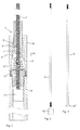
- the in Fig. 1 illustrated telescopic holder 1 according to a first embodiment of the present invention comprises a first holder body 2 and a second holder body 3, which are formed in their common longitudinal direction against each other displaceable.
- the second holding body 3 is formed as a hollow body, in which the first holding body 2 can be inserted.
- the two holding bodies 2, 3 are fixed relative to one another in any position by clamping bodies 4 designed as balls in this exemplary embodiment, the clamping bodies 4 being part of a clamping device 5 which is arranged on an end of the second holding body 3 facing the first holding body 2 ,
- the clamping device 5 is a movably mounted clamping guide 6 with a clamping body 4 receiving cage 7 and in the longitudinal direction of the holder body 2, 3 extending, surrounded by the cage 7 and extending from this further in the longitudinal direction of the holding body 2, 3 extending passage channel 8 is provided , in which the first holding body 2 is guided.
- the clamping device 5 has a clamping surface 9, which tapers in the longitudinal direction of the holding bodies 2, 3, wherein the clamping bodies 4 guided in the cage 7 are formed on the outer surface of the first holding body 2 and the clamping surface 9 in the inner surface opposite the outer surface of the first holding body 2 Clamping position frictionally abut.
- the clamping body 4 clamp the first holder body 2 in the clamping device 5 thus in the clamping direction 10 shown by an arrow, so that the first holding body 2 and the second holding body 3 can not be moved counter to the clamping direction 10.
- the tapered clamping surface 9 runs counter to the clamping direction 10 to taper.
- the tapered clamping surface 9 is preferably conical.
- the clamping guide 6 with the cage 4 guiding the clamping body 4 is opposite to the clamping direction 10, i. in the direction of the taper of the clamping surface 9, biased by a spring 11, which presses the clamping guide 6 with the cage 7 and the clamping bodies guided therein in the direction of the tapered clamping surface 9.
- the clamping guide 6 and the cage 7 form a structural unit, which can be made of a homogeneous piece of material or of two or more components by their permanent assembly, eg. By screwing, gluing or welding.
- the spring 11 presses to the terminal 6 opposite end of the clamping device 5 to an inner sleeve 12, which is screwed with an external thread into an internal thread of the clamping device 5 and thereby the clamping surface 9 in the clamping device 5 in the clamping direction 10 completes.
- the inner sleeve 12 also has an external thread which is screwed into an internal thread of the end of the second holding body 3, so that the clamping device 5 is screwed to the second holding body 3 through the inner sleeve 12.
- the clamping bodies 4 of the clamping device 5 clamp the first holding body 2, therefore, the first holding body 2 and the second holding body 3 of the telescopic holder 1 in the then present position relative to each other fixed so that the telescopic holder can serve as a telescopically adjustable holder for fixing any objects.
- the first holding body 2 has at its end accommodated in the second holding body 3 a widening 13, which in the illustrated example is designed as a separate end stop is centered on the first holding body 2 on the inner diameter of the second holding body 3 and is slightly smaller than the hollow dimension of the second holding body 3, so that the widening 13 forms a linear guide of the first holding body 2 in the second holding body 3.
- a widening 13 which in the illustrated example is designed as a separate end stop is centered on the first holding body 2 on the inner diameter of the second holding body 3 and is slightly smaller than the hollow dimension of the second holding body 3, so that the widening 13 forms a linear guide of the first holding body 2 in the second holding body 3.
- the telescopic holder 1 is the suspension of a lamp 14 on the ceiling 15 of a room, wherein the first holder body 2 is fixed to a transformer housing 16 and the second holder body is directly connected to the lamp 14. Since the lamp 14 in the illustrated embodiment is a low-voltage lamp, the metallically formed first and second holding bodies 2, 3 can also be used for the power supply of the lamp 14.
- FIG. 2 the mutually facing ends of the first holder body 2 and the second holder body 3 are shown in detail together with the clamping device 5 of the telescopic holder 1 connecting them, the first holder body 2 being different from the one shown in FIG Fig. 1 is designed as a continuous threaded rod.
- the telescopic holder 1 according to the invention is constructed in a modular manner, wherein the individual modules (parts) are the first and second holder body 2, 3 and the clamping device 5, which are modularly connected to each other for mounting the telescopic holder 1 or can be connected.
- the clamping guide 6 extends in its part surrounding the feedthrough channel 8 up to the clamping device 5 in the direction of the first holding body 2, i. against the clamping direction 10, also, so that the clamping by pressing the clamping guide 6 (and thus the feedthrough channel 6) in the direction of the clamping direction 10 can be easily solved.
- Fig. 3 is shown in a side view as an exploded view of the structure of the first holder body 2 with an external thread at its ends.
- the end 13 formed as an end stop with a centered blind bore and internal thread is widened.
- the external thread at the other end of the first holder body 2 serves, for example, the fixing to a body, with which the telescopic holder is connected.
- Fig. 4 shows in side view another embodiment of a widening 17, which is also designed as an end stop and bolted to the first holding body 2. Their extension in the longitudinal direction of the first holding body 2 is compared to the expansion 13, however, significantly shortened.
- the widening 17 is constructed in the manner of a disk, so that the widening 17 slides in the second holding body 3 designed as a hollow body with a lower running resistance.
- inventive first holder body 2 are exemplified, which are formed as a rod with recess cross-sections 18 and 19, wherein the recess cross-sections 18, 19 are preferably arranged equidistantly on the first holder body 2.
- Fig. 5 shows a rectangular recess cross-section 18 and Fig. 6 a concave recess cross section 19.
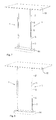
- FIGS. 7 and 8 shown application examples of the telescopic holder 1 according to the invention for the case of suspensions of lamps 14 on ceilings 15 of a room, the modular design of the telescopic holder according to the invention can be particularly well recognized.
- a second holding body 3 is fixed to the ceiling 15, at the end of a clamping device 5 is in which a first holder body 2 is fixed. In the further course of the first holding body 2, this engages again in a clamping device 5 of a next (second) second holding body 3, which is connected to the lamp 14.
- two of the above-described telescopic holder 1 for suspending the lamp 14 are provided. This shows that any length of the telescopic holder 1 can be achieved by alternating juxtaposition of the first holder body 2 and second holder body 3, wherein - like Fig. 8 shows - is irrelevant in which Sequence, the first holder body 2 and second holder body 3 alternate.
- a first holder body 2 is fixed by a suitable fastening means on the ceiling 15 and engages in the clamping device 5 of a second holder body 3, at the opposite end of a further clamping device 5 is provided, in which a further (second) first Holding body 2 is clamped, which is then connected via a fastening device with the lamp 14.
- Fig. 9 is the according to Fig. 7 shown telescopic holder 1 is applied to hold a suspended ceiling formed from different ceiling elements 20 under the ceiling 15 of a room, the telescopic holder 1 are connected to longitudinal and transverse struts 21 which hold the ceiling elements 20.
- Fig. 10 shows a further application for the telescopic holder 1 according to the invention, which is mounted vertically standing on a bottom plate 22 upwards.
- a second holding body 3 is fixed on the bottom plate 22, on its side facing away from the bottom plate 22 a clamping device 5, in which a first holder body 2 is clamped to which a monitor 23 is secured on its rear side by screw holder 24.
- two telescopic holders 1 are parallel spaced on the bottom plate 22nd
- this telescope holder 1 is the same in the installation application as the telescope holder 1 in the suspension application.
- a clamping action in the direction of insertion direction of the first holder body 2 in the second holder body 3 must be achieved, so that the clamping direction 10 is not against a withdrawal of the first holder body 2 from the second holder body 3 but against insertion of the first holder body 2 in the second holder body 3 must act.
- the clamping device 5 as they are, for example.
- Fig. 2 is shown enlarged, the clamping surface 9 formed tapered in the opposite direction, so that the insertion of the first holder body 2 in the second holder body 3 is reliably avoided.
- FIG. 2 shows a section of a clamping device 25 according to the invention for the telescope holder 1, which basically resembles the clamping device 5 described above.
- the clamping device 25 has in the same way a clamping guide 6 with a cage 7, are guided in the clamping body 26, which will be described in more detail below.
- the clamping body 26 are in a comparable manner to a tapered inner surface 9 of the clamping device 25, which serves as a clamping surface, and act on a received in a through-channel 8 of the clamping guide 6 Klemmgut 28, in which it is the first holder body 2 of the invention Telescope holder 1 acts.
- it can also be other clamping material 28, such as, for example, a rod, a rope, a pipe or a wire, act on the 25 fixed objects with the clamping device, for example, to be suspended.
- the bias of the cage 7 in the clamping device 25 serving spring is in Fig. 11 for the sake of clarity not shown.
- the functioning The clamping device 25 corresponds to the previously described mode of operation of the clamping device 5.
- the only difference of the present invention independently of the telescope holder 1 usable clamping device 25 is in the form of the clamping body 26, which are formed as a cylinder.
- the cylindrical clamping body 26 are guided in the cage 7 of the clamping guide such that its rotationally symmetrical surface (outer circumference of the cylinder) rests along the cylinder axis of the clamping material 28 and - as long as no clamping effect is achieved - a rolling of the clamping body 26 on the outer surface of the clamping 28 allowed in the longitudinal direction.
- the diameter of the clamping body 26 provided as a cylinder may be smaller than the ball diameter, so that the outer dimensions of the clamping device 25 may be smaller overall than the dimensions of the clamping device 5 described above.
- FIGS. 12 and 13 show the clamping guide 6 with the cage 7 and guided therein cylindrical clamping bodies 26 in the side view and a three-dimensional representation, wherein Fig. 13 also the opening of the feedthrough channel 8 for the clamped material 28 shows.
- Fig. 14 shows a three-dimensional view of the cylindrical clamp body 26th
- cylindrically constructed clamping body 26 may also be an elliptical clamping body 29, as in Fig. 15 shown, or a cylindrical clamp body 30 may be provided with rounded edges 31, as in Fig. 16 shown, which are guided instead of the clamping body 26 in the cage 7 of the clamping guide 6 of the clamping device 25.
- the elliptical clamping body 29 or the cylindrical clamping body 30 with rounded edge 31 corresponding to the FIGS. 15 and 16 can be constructed very compact and allow a hook-free or -arm leadership in the intended rolling direction about the axis of symmetry in its longitudinal axis.
Landscapes
- Engineering & Computer Science (AREA)
- General Engineering & Computer Science (AREA)
- Mechanical Engineering (AREA)
- Clamps And Clips (AREA)
- Telescopes (AREA)
Applications Claiming Priority (1)
| Application Number | Priority Date | Filing Date | Title |
|---|---|---|---|
| DE102012103183A DE102012103183A1 (de) | 2012-04-13 | 2012-04-13 | Teleskophalter und Klemmeinrichtung |
Publications (2)
| Publication Number | Publication Date |
|---|---|
| EP2649902A2 true EP2649902A2 (fr) | 2013-10-16 |
| EP2649902A3 EP2649902A3 (fr) | 2017-06-28 |
Family
ID=48095637
Family Applications (1)
| Application Number | Title | Priority Date | Filing Date |
|---|---|---|---|
| EP13163134.3A Withdrawn EP2649902A3 (fr) | 2012-04-13 | 2013-04-10 | Support télescopique avec dispositif de serrage |
Country Status (2)
| Country | Link |
|---|---|
| EP (1) | EP2649902A3 (fr) |
| DE (1) | DE102012103183A1 (fr) |
Cited By (5)
| Publication number | Priority date | Publication date | Assignee | Title |
|---|---|---|---|---|
| CN108663242A (zh) * | 2017-03-31 | 2018-10-16 | 浙江大学 | 一种常规三轴试验扰动土体制样装置及方法 |
| EP3633118A1 (fr) * | 2018-10-02 | 2020-04-08 | DOKA GmbH | Support de coffrage et dispositif de support de coffrage |
| GB2560418B (en) * | 2017-01-16 | 2020-06-17 | Gripple Ltd | Securing device |
| CN114104530A (zh) * | 2021-12-30 | 2022-03-01 | 沃德林科环保设备(北京)有限公司 | 一种新型内浮顶储罐可调节高度支腿 |
| WO2024039802A1 (fr) * | 2022-08-17 | 2024-02-22 | Xfix8 Llc | Dispositifs, systèmes et procédés de fixation externe |
Citations (6)
| Publication number | Priority date | Publication date | Assignee | Title |
|---|---|---|---|---|
| DE1055201B (de) | 1958-05-16 | 1959-04-16 | Ferdinand Graef | Teleskopartig ausziehbare Trag- oder Stuetzvorrichtung fuer Gardinen, Vorhaenge, Handtuecher, Waeschestuecke und sonstige Gebrauchs- und Schau-stellungsgenstaende |
| CH639177A5 (en) | 1979-07-20 | 1983-10-31 | Willi Markus | Detachable clamping device for pipes which can be pushed into one another like a telescope |
| US5400472A (en) | 1993-08-04 | 1995-03-28 | Chang; Fu J. | Handle assembly of a bagggage cart |
| DE19919231A1 (de) | 1999-04-28 | 2000-11-02 | Moebelwerk Ilse Gmbh & Co Kg | Teleskopierbare Säule |
| EP2233817A1 (fr) | 2009-03-27 | 2010-09-29 | König & Meyer GmbH & Co. KG | Colonne de support, notamment colonne de pupitre ou de support de microphone |
| DE102004041757B4 (de) | 2004-08-28 | 2011-07-28 | Drobek, Werner, 97346 | Verbindungselement |
Family Cites Families (7)
| Publication number | Priority date | Publication date | Assignee | Title |
|---|---|---|---|---|
| DE8503494U1 (de) * | 1985-05-09 | Kotzolt, Michael, 4920 Lemgo | Klemmvorrichtung für Seile | |
| US909223A (en) * | 1908-08-10 | 1909-01-12 | Ransom & Randolph Company | Dental stool or the like. |
| JPH0447454Y2 (fr) * | 1985-03-12 | 1992-11-10 | ||
| DE19507815C2 (de) * | 1995-03-06 | 1997-04-10 | Seil & Netztechnik Reutlinger | Halterung für Seile |
| DE10055201A1 (de) | 2000-11-07 | 2002-05-08 | Prokent Ag | Vorrichtung zum Kompaktieren von leeren Getränkebehältern |
| DE102005007737B4 (de) * | 2005-02-18 | 2012-03-22 | Seil- & Netztechnik Reutlinger Gmbh | Halter |
| DE202011106507U1 (de) * | 2010-11-08 | 2011-12-08 | BüMI Präzisionszerspanungs GmbH & Co. KG | Vorrichtung zur Längenverstellung einer Stange |
-
2012
- 2012-04-13 DE DE102012103183A patent/DE102012103183A1/de not_active Ceased
-
2013
- 2013-04-10 EP EP13163134.3A patent/EP2649902A3/fr not_active Withdrawn
Patent Citations (6)
| Publication number | Priority date | Publication date | Assignee | Title |
|---|---|---|---|---|
| DE1055201B (de) | 1958-05-16 | 1959-04-16 | Ferdinand Graef | Teleskopartig ausziehbare Trag- oder Stuetzvorrichtung fuer Gardinen, Vorhaenge, Handtuecher, Waeschestuecke und sonstige Gebrauchs- und Schau-stellungsgenstaende |
| CH639177A5 (en) | 1979-07-20 | 1983-10-31 | Willi Markus | Detachable clamping device for pipes which can be pushed into one another like a telescope |
| US5400472A (en) | 1993-08-04 | 1995-03-28 | Chang; Fu J. | Handle assembly of a bagggage cart |
| DE19919231A1 (de) | 1999-04-28 | 2000-11-02 | Moebelwerk Ilse Gmbh & Co Kg | Teleskopierbare Säule |
| DE102004041757B4 (de) | 2004-08-28 | 2011-07-28 | Drobek, Werner, 97346 | Verbindungselement |
| EP2233817A1 (fr) | 2009-03-27 | 2010-09-29 | König & Meyer GmbH & Co. KG | Colonne de support, notamment colonne de pupitre ou de support de microphone |
Cited By (7)
| Publication number | Priority date | Publication date | Assignee | Title |
|---|---|---|---|---|
| GB2560418B (en) * | 2017-01-16 | 2020-06-17 | Gripple Ltd | Securing device |
| US10883569B2 (en) | 2017-01-16 | 2021-01-05 | Gripple Limited | Securing device |
| CN108663242A (zh) * | 2017-03-31 | 2018-10-16 | 浙江大学 | 一种常规三轴试验扰动土体制样装置及方法 |
| EP3633118A1 (fr) * | 2018-10-02 | 2020-04-08 | DOKA GmbH | Support de coffrage et dispositif de support de coffrage |
| CN114104530A (zh) * | 2021-12-30 | 2022-03-01 | 沃德林科环保设备(北京)有限公司 | 一种新型内浮顶储罐可调节高度支腿 |
| CN114104530B (zh) * | 2021-12-30 | 2024-05-24 | 沃德林科环保设备(北京)有限公司 | 一种新型内浮顶储罐可调节高度支腿 |
| WO2024039802A1 (fr) * | 2022-08-17 | 2024-02-22 | Xfix8 Llc | Dispositifs, systèmes et procédés de fixation externe |
Also Published As
| Publication number | Publication date |
|---|---|
| DE102012103183A1 (de) | 2013-10-17 |
| EP2649902A3 (fr) | 2017-06-28 |
Similar Documents
| Publication | Publication Date | Title |
|---|---|---|
| DE202014002813U1 (de) | Temporäre Wandstütze | |
| EP2649902A2 (fr) | Support télescopique avec dispositif de serrage | |
| DE4030978C2 (de) | Verbindungseinrichtung für Rohre | |
| CH687221A5 (de) | Automatische Klemmvorrichtung fuer Drahtseile oderRundprofile sowie Verwendung derselben. | |
| WO2009109287A1 (fr) | Support de câble pour suspendre un objet, en particulier un luminaire | |
| EP4067716B1 (fr) | Dispositif de montage de section de tube | |
| DE202017001316U1 (de) | Mehrfachbefestigungsmittel mit zumindest einem Formschluss-Verbindungsabschnitt sowie Befestigungssystem mit einem solchen Mehrfachbefestigungsmittel | |
| DE3823000C2 (de) | Befestigungselement | |
| DE9320113U1 (de) | Klemmverbinder | |
| DE2053934C2 (de) | Längenverstellbare Tragstange für Vorhänge, Lampen, Dekorations- oder andere Gebrauchsgegenstände | |
| EP2865902A1 (fr) | Dispositif de liaison pour un système de construction et système de construction | |
| DE20021708U1 (de) | Fangvorrichtung für eine Aufhängeeinrichtung | |
| DE102016115181A1 (de) | Sanitärarmatur | |
| DE102007014484B4 (de) | Vorrichtung zum lösbaren Verbinden | |
| DE29720821U1 (de) | Längenverstellbare Stange | |
| EP3441536A1 (fr) | Dispositif de fixation d'un cadre pour une unité sanitaire | |
| DE10234603B4 (de) | Spanneinrichtung für Werkzeuge oder Werkstücke | |
| DE20110322U1 (de) | Anordnung zum Verbinden von insbesondere rohrförmigen Gegenständen | |
| DE19739733A1 (de) | Vorrichtung zum Verbinden eines Flachelements mit einem Stabelement | |
| DE10352803A1 (de) | Verbindung von Mastelementen oder Rohrstücken von Leuchten | |
| DE202019106932U1 (de) | Montagevorrichtung zum Errichten einer Trennwand | |
| DE102005016310B4 (de) | Personenführung | |
| DE202010008118U1 (de) | Halter sowie Anordnung umfassend einen solchen Seilhalter und ein Trägerprofil | |
| DE202015106783U1 (de) | Träger für eine Profilschiene einer Vorhangschienengarnitur sowie damit ausgerüstete Vorhangschienengarnitur | |
| DE29505791U1 (de) | Befestigungselement zum lösbaren Verbinden eines Mehrkantrohres |
Legal Events
| Date | Code | Title | Description |
|---|---|---|---|
| PUAI | Public reference made under article 153(3) epc to a published international application that has entered the european phase |
Free format text: ORIGINAL CODE: 0009012 |
|
| AK | Designated contracting states |
Kind code of ref document: A2 Designated state(s): AL AT BE BG CH CY CZ DE DK EE ES FI FR GB GR HR HU IE IS IT LI LT LU LV MC MK MT NL NO PL PT RO RS SE SI SK SM TR |
|
| AX | Request for extension of the european patent |
Extension state: BA ME |
|
| PUAL | Search report despatched |
Free format text: ORIGINAL CODE: 0009013 |
|
| AK | Designated contracting states |
Kind code of ref document: A3 Designated state(s): AL AT BE BG CH CY CZ DE DK EE ES FI FR GB GR HR HU IE IS IT LI LT LU LV MC MK MT NL NO PL PT RO RS SE SI SK SM TR |
|
| AX | Request for extension of the european patent |
Extension state: BA ME |
|
| RIC1 | Information provided on ipc code assigned before grant |
Ipc: A47B 9/20 20060101AFI20170522BHEP Ipc: F16B 7/18 20060101ALN20170522BHEP Ipc: F16B 7/16 20060101ALN20170522BHEP Ipc: F16B 7/14 20060101ALI20170522BHEP |
|
| STAA | Information on the status of an ep patent application or granted ep patent |
Free format text: STATUS: THE APPLICATION HAS BEEN PUBLISHED |
|
| STAA | Information on the status of an ep patent application or granted ep patent |
Free format text: STATUS: THE APPLICATION IS DEEMED TO BE WITHDRAWN |
|
| 18D | Application deemed to be withdrawn |
Effective date: 20171103 |