EP2644682B1 - Coke oven monitoring method, furnace wall management method, and monitoring system - Google Patents
Coke oven monitoring method, furnace wall management method, and monitoring system Download PDFInfo
- Publication number
- EP2644682B1 EP2644682B1 EP11842518.0A EP11842518A EP2644682B1 EP 2644682 B1 EP2644682 B1 EP 2644682B1 EP 11842518 A EP11842518 A EP 11842518A EP 2644682 B1 EP2644682 B1 EP 2644682B1
- Authority
- EP
- European Patent Office
- Prior art keywords
- chamber
- chamber wall
- image data
- data
- cycle
- Prior art date
- Legal status (The legal status is an assumption and is not a legal conclusion. Google has not performed a legal analysis and makes no representation as to the accuracy of the status listed.)
- Active
Links
Images


Classifications
-
- C—CHEMISTRY; METALLURGY
- C10—PETROLEUM, GAS OR COKE INDUSTRIES; TECHNICAL GASES CONTAINING CARBON MONOXIDE; FUELS; LUBRICANTS; PEAT
- C10B—DESTRUCTIVE DISTILLATION OF CARBONACEOUS MATERIALS FOR PRODUCTION OF GAS, COKE, TAR, OR SIMILAR MATERIALS
- C10B41/00—Safety devices, e.g. signalling or controlling devices for use in the discharge of coke
-
- G—PHYSICS
- G06—COMPUTING OR CALCULATING; COUNTING
- G06T—IMAGE DATA PROCESSING OR GENERATION, IN GENERAL
- G06T7/00—Image analysis
- G06T7/60—Analysis of geometric attributes
- G06T7/62—Analysis of geometric attributes of area, perimeter, diameter or volume
-
- C—CHEMISTRY; METALLURGY
- C10—PETROLEUM, GAS OR COKE INDUSTRIES; TECHNICAL GASES CONTAINING CARBON MONOXIDE; FUELS; LUBRICANTS; PEAT
- C10B—DESTRUCTIVE DISTILLATION OF CARBONACEOUS MATERIALS FOR PRODUCTION OF GAS, COKE, TAR, OR SIMILAR MATERIALS
- C10B29/00—Other details of coke ovens
- C10B29/06—Preventing or repairing leakages of the brickwork
-
- C—CHEMISTRY; METALLURGY
- C10—PETROLEUM, GAS OR COKE INDUSTRIES; TECHNICAL GASES CONTAINING CARBON MONOXIDE; FUELS; LUBRICANTS; PEAT
- C10B—DESTRUCTIVE DISTILLATION OF CARBONACEOUS MATERIALS FOR PRODUCTION OF GAS, COKE, TAR, OR SIMILAR MATERIALS
- C10B33/00—Discharging devices; Coke guides
- C10B33/08—Pushers, e.g. rams
- C10B33/10—Pushers, e.g. rams for horizontal chambers
-
- C—CHEMISTRY; METALLURGY
- C10—PETROLEUM, GAS OR COKE INDUSTRIES; TECHNICAL GASES CONTAINING CARBON MONOXIDE; FUELS; LUBRICANTS; PEAT
- C10B—DESTRUCTIVE DISTILLATION OF CARBONACEOUS MATERIALS FOR PRODUCTION OF GAS, COKE, TAR, OR SIMILAR MATERIALS
- C10B45/00—Other details
-
- G—PHYSICS
- G01—MEASURING; TESTING
- G01N—INVESTIGATING OR ANALYSING MATERIALS BY DETERMINING THEIR CHEMICAL OR PHYSICAL PROPERTIES
- G01N21/00—Investigating or analysing materials by the use of optical means, i.e. using sub-millimetre waves, infrared, visible or ultraviolet light
- G01N21/84—Systems specially adapted for particular applications
- G01N21/88—Investigating the presence of flaws or contamination
- G01N21/95—Investigating the presence of flaws or contamination characterised by the material or shape of the object to be examined
- G01N21/954—Inspecting the inner surface of hollow bodies, e.g. bores
-
- G—PHYSICS
- G06—COMPUTING OR CALCULATING; COUNTING
- G06T—IMAGE DATA PROCESSING OR GENERATION, IN GENERAL
- G06T7/00—Image analysis
- G06T7/0002—Inspection of images, e.g. flaw detection
- G06T7/0004—Industrial image inspection
-
- G—PHYSICS
- G06—COMPUTING OR CALCULATING; COUNTING
- G06T—IMAGE DATA PROCESSING OR GENERATION, IN GENERAL
- G06T7/00—Image analysis
- G06T7/0002—Inspection of images, e.g. flaw detection
- G06T7/0004—Industrial image inspection
- G06T7/0008—Industrial image inspection checking presence/absence
-
- H—ELECTRICITY
- H04—ELECTRIC COMMUNICATION TECHNIQUE
- H04N—PICTORIAL COMMUNICATION, e.g. TELEVISION
- H04N7/00—Television systems
- H04N7/18—Closed-circuit television [CCTV] systems, i.e. systems in which the video signal is not broadcast
Definitions
- the present invention relates to a method for monitoring inside a chamber of a coke oven in which changes in the state of chamber walls in the coke oven can be quantitatively monitored with excellent accuracy, a management method for the chamber wall of the coke oven, and a monitoring system.
- a coke oven is configured by carbonization chambers and combustion chambers that are alternately provided along a coke oven battery. Heat in the combustion chamber transferred to the carbonization chamber dry distills coal charged in the carbonization chamber so as to produce coke.
- JP-A-2001-40359 discloses a method where, in pushing the red-hot coke from the carbonization chamber of a coke oven, the pushing resistance loaded on the pushing ram of the pusher is measured, during which time the width of the oven is continuously measured with a pair of non-contact distance meters mounted on the ram, and the position of oven width detection is continuously imaged with an image pickup device. Then, the position of a rise in the pushing resistance is determined according to the wave form of the detected pushing resistance and the data on the oven width. From the image of the position of a rise in the pushing resistance, the cause for the rise is determined to be carbon deposition, wall damage, the property of the fed coal, or the state of carbonization, and whether or not the oven wall requires repair is judged.
- the state of chamber walls changes day by day in the continuous operation of a coke oven. Some incidental change may cause extrusion troubles such as a stuck in a carbonization chamber. There are thus demands for a system that realizes constant monitoring on changes in the state of chamber walls.
- the present invention has been achieved in view of the above problems in the conventional method for monitoring inside the chamber. It is an object of the present invention to a method for monitoring inside a chamber of a coke oven in which changes in the state of chamber walls in the coke oven can be quantitatively monitored with excellent accuracy, a management method for the chamber wall of the coke oven, and a monitoring system.
- the problem relates to quantitatively monitoring changes in the state of chamber walls in the coke oven with excellent accuracy.
- the present disclosure provides three modes, namely, a method for monitoring inside a chamber of a coke oven changes in the state of chamber walls in the coke oven, a management method for the chamber wall of the coke oven of managing a tendency in the state of the chamber walls, and a monitoring system.
- a method for monitoring inside a chamber of a coke oven includes:
- the extrusion cycle means a process until it pushes out the coke generated by dry distillation from the carbonization chamber after filling a coal into the carbonization chamber. This process (cycle) is repeated.
- the chamber width means a distance between chamber walls.
- a method of determining an chamber wall abnormality including: calculating and numerically converting a finite difference between the chamber width data in the current extrusion cycle and the chamber width data in the past extrusion cycle and a finite difference between an area of an chamber wall damaged portion in the chamber wall image data in the current extrusion cycle and an area of an chamber wall damaged portion in the chamber wall image data in the past extrusion cycle; and comparing the finite difference value between the chamber width data with the predetermined value for chamber width data, and comparing the finite difference value between the chamber wall image data with the predetermined value for chamber wall image data.
- "Finite difference value" in the present invention corresponds to "the calculated and numerically processed finite difference” .
- a management method for the chamber wall of the coke oven includes:
- a monitoring system includes:
- An extrusion cycle in the present invention indicates a series of the processes from charging coal to extrusion of coke, which is counted as one cycle.
- Past chamber width data include (a) data obtained in the last extrusion cycle, (b) data obtained in the extrusion cycle subsequent to repair, and (c) data obtained in an arbitrary number of extrusion cycles.
- the present invention advantageously realizes constant, accurate, and quantitative monitoring on such changes in the state of chamber walls in a coke oven.
- Fig. 1 is a configuration diagram of the monitoring system to see inside the camber of the coke oven (hereinafter, abbreviated as the monitoring system) according to the present invention.
- a coke extruder 1 includes an extrusion ram 4 that has a ram head 2 and a ram beam 3 for horizontally reciprocating the ram head 2.
- Coke dry distilled and red heated in a carbonization chamber is extruded by the ram head 2 from a PS (pusher side: coke extruder side) carbonization chamber port to a CS (coke side: coke discharger side) carbonization chamber port.
- PS pushher side: coke extruder side
- CS coke side: coke discharger side
- the support stand 5 is provided with a permanent chamber width measurement device (hereinafter, abbreviated as the chamber width measurement device) 6 and a permanent in-chamber observation device (hereinafter, abbreviated as the in-chamber observation device) 7.
- the wording "permanent" herein is indicative of being permanently provided to the extrusion ram.
- the chamber width measurement device 6 measures a chamber width during coke extrusion (direction A) or while the extrusion ram 4 is returned from the CS carbonization chamber port to the PS carbonization chamber port after completion of the coke extrusion (direction B).
- the chamber width measurement device 6 may be embodied by a contactless range finder such as a laser displacement sensor.
- the in-chamber observation device 7 is equipped with a CCD camera, and sequentially photographs chamber wall images during coke extrusion (direction A) or while the extrusion ram 4 is returned after completion of the coke extrusion (direction B).
- reference sign ⁇ indicates a view angle of the CCD camera, that is, the (vertical) range photographed by the CCD camera.
- the chamber width measurement device 6 and the in-chamber observation device 7 are respectively provided on the support stand 5 so as to measure and observe a location on a wall surface at a certain height (the height of 3.5 m from the bottom of the carbonization chamber in the illustrated example) H.
- the position of the extrusion ram 4 shifting in the coke oven is detected by an encoder (position detection means) 8 that is attached to the extrusion ram (the ram beam 3 in the illustrated example). Positional information on the extrusion ram 4 outputted from the encoder 8 is transmitted by way of a cable 9 to a computer 10 in an extruder operation room.
- the computer 10 is provided with a chamber width/chamber wall image data extraction unit 10a, a chamber width/chamber wall image data analysis and processing unit 10b, and an alarm output unit 10c.
- the chamber width/chamber wall image data extraction unit 10a extracts, for constant distances, chamber width data and chamber wall image data obtained between the PS carbonization chamber port and the CS carbonization chamber port (measurement can be made while the extrusion ram is extruded or withdrawn), with use of positional information outputted from the encoder 8. It is thus possible to obtain chamber width data and chamber wall image data in different extrusion cycles (hereinafter, simply referred to as cycles in some cases) at a predetermined location in the same carbonization chamber.
- the chamber width data and the chamber wall image data thus extracted are accumulated in correspondence with the positional information in a database (accumulation means) 11 to be described later. It is possible to read data by accessing the database 11 from a terminal device (computer) 12 in an office.
- the computer 10 and the database 11 can be connected to each other by wired connection or by wireless connection.
- Chamber width data and chamber wall image data outputted respectively from the chamber width measurement device 6 and the in-chamber observation device 7 are transmitted by way of signal/power cables 13 to the computer 10.
- Chamber wall image data is also transmitted by way of a signal cable 14 to a monitor 15 in the extruder operation room, so as to enable real-time observation of the state in the carbonization chamber.
- the chamber width/chamber wall image data analysis and processing unit 10b analyzes chamber width data and chamber wall image data extracted by the chamber width/chamber wall image data extraction unit 10a, in accordance with a program preliminarily stored.
- data in the current extrusion cycle and past data are compared with each other for respective same positions in the direction of extruding or in the direction of withdrawing the extrusion ram between the PS carbonization chamber port and the CS carbonization chamber port.
- Each change therebetween is calculated as a finite difference.
- the alarm output unit 10c reports abnormalities to an operator in the operation room upon detection, in the analysis results made by the chamber width/chamber wall image data analysis and processing unit 10b, of in-chamber abnormalities such as adhesion, growth, and peeling off of carbon, which lead to increase in power used for extrusion.
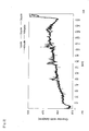
- Fig. 2 is a graph indicating measurement results of chamber widths measured by the chamber width measurement device 6.
- the transverse axis indicates positions between the PS carbonization chamber port and the CS carbonization chamber port, with the PS carbonization chamber port being set at 0 cm.
- the ordinate axis indicates chamber width data (mm).
- the chamber width data in the graph collectively indicates chamber widths obtained in the first, second, third, 40th, and 100th cycles.
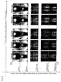
- Fig. 3 is an explanatory view showing chamber wall images in respective extrusion cycles photographed with use of the in-chamber observation device 7.
- the extrusion cycles are indicated in the transverse direction (so as to correspond to the first, second, third, 40th, and 100th cycles in the graph of Fig. 2 ), while the positions between the PS carbonization chamber port and the CS carbonization chamber port are indicated in the ordinate direction.
- the PS carbonization chamber port is set at 0 cm.
- chamber width measurement positions and image extraction positions are matched in the respective extrusion cycles, on the basis of positional information outputted from the encoder 8.
- finite differences are calculated between chamber width data measured at the same locations as well as between chamber wall image data photographed at the same locations in the respective extrusion cycles.
- the measurement results are obtained as numerical values in the measurement of chamber widths. Thus, comparison is made between chamber width data at the same position in two different cycles to obtain a finite difference.
- the state of the chamber wall is numerically converted with use of chamber width data measured by the chamber width measurement device 6 and chamber wall image data photographed by the in-chamber observation device 7.
- the area of a peeled off portion is calculated from chamber wall image data, and the depth or the like of the peeled off portion is calculated from chamber width data. It is therefore possible to grasp gouging or thickening of the chamber wall due to adhesion and growth of carbon at the measurement point.
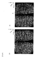
- Figs. 4(a) and 4(b) are chamber wall images used for calculation of the area of the changed portion in the state of the chamber wall.
- Fig. 4(a) shows the chamber wall image in the last cycle
- Fig. 4(b) shows the chamber wall image in the current cycle.
- the PS carbonization chamber port is shown on the back side of the chamber wall image, while the CS carbonization chamber port is shown on the front side of the chamber wall image.
- Set in correspondence with these chamber wall images are the Z axis in the horizontal direction along the length of the carbonization chamber (extrusion direction), the Y axis in the vertical direction, and the X axis along the width of the carbonization chamber.
- a range S surrounded with an ellipse indicates an area of a peeled off portion where carbon is peeled off.
- the peeled off portion is numerically converted to obtain an area of the peeled off portion in the Z-Y plane.
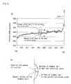
- Fig. 5(a) is a graph of chamber width data used for calculation of the depth and the range of the changed portion in the state of the chamber wall.
- This graph in which the transverse axis indicates the Z axis and the ordinate axis indicates the X axis, indicates chamber width data in the last cycle as well as chamber width data in the current cycle.
- the chamber walls opposite to each other are provided so as to gradually expand from the PS carbonization chamber port to the CS carbonization chamber port. Accordingly, the graph of chamber width data draws lines generally slanted upward toward the CS carbonization chamber port. However, chamber width data has a peak where carbon is peeled off the chamber wall. In this graph, the chamber width data in the current cycle has a larger peak P as compared with the chamber width data in the last cycle.
- a distance Z L along the Z axis and a distance X L along the X axis are calculated to obtain the depth of the peeled off portion from the distance X L along the X axis (see Fig. 5(b) ).
- an area S of the peeled off portion is obtained from the distance X L along the X axis and the chamber wall image data.
- the volume of the peeled off portion can be obtained from the area S.
- the range (diameter) of the peeled off portion can be checked from the distance Z L along the Z axis.
- the monitoring system can quantitatively calculate the change in the state of the chamber wall with excellent accuracy, as the depth, the area, and the volume.
- Figs. 6(a) and 6(b) configure an explanatory view conceptually showing graphs of numerical transition used for abnormality detection ( Fig. 6(a) ) and tendency management ( Fig. 6(b) ) in accordance with the analysis results of chamber width data and the analysis results of chamber wall image data.
- carbon is assumed to be peeled off in the 101st cycle.
- the analysis results of chamber width data and chamber wall image data are sequentially accumulated in the database (accumulation means) 11 shown in Fig. 1 , and can be accessed from the terminal device 12.
- the graph of Fig. 6(a) is used for abnormality detection, indicating the changes in the state of the chamber wall by means of the difference between the current cycle and the last cycle as to each of the cycles, which is obtained from the analysis results of chamber width data and chamber wall image data from the first cycle to the 150th cycle in the same carbonization chamber.
- the graph from the first cycle to the 100th cycle indicates normal transition. Carbon gradually adheres to the chamber wall as the number of cycles increases. However, there is no significant change in the comparison between the last cycle and the current cycle. Accordingly, no numerical change is observed, and the graph indicates transition along the transverse axis.
- the chamber width data and the chamber wall image data obtained in the current extrusion cycle is remarkably changed from the chamber width data and the chamber wall image data obtained in the past (last) extrusion cycle. Therefore, determination of an chamber wall abnormality can be made depending on whether or not the changes exceed predetermined values for chamber widths and chamber wall images.
- the graph indicates transition along the transverse axis, similarly to the graph showing transition from the first cycle to the 100th cycle.
- the graph of Fig. 6(b) is used for management of a tendency in the state of the chamber wall.
- the graph indicates the changes in the state of the chamber wall by means of the difference between the current cycle and the last cycle as to each of the cycles, which is obtained from the analysis results of chamber width data and chamber wall image data from the first cycle to the 150th cycle in the same carbonization chamber.
- the first cycle in this case is set subsequently to repair (specific extrusion cycle) and is assumed to have a reference value (reference data).
- the reference value can be set arbitrarily.
- the graph indicates normal transition from the first cycle to the 100th cycle. Carbon gradually adheres to the chamber wall as the number of cycles increases. The change between the first cycle (reference value) and the current cycle is larger as the number of cycles increases. Therefore, the graph indicates transition slanted upward.
- the chamber width data and the chamber wall image data obtained in the current extrusion cycle are remarkably changed from chamber width data and chamber wall image data that are accumulated by obtaining in the past extrusion cycles (reference data).
- Fig. 6(b) can be used not only for tendency management but also for determination of an chamber wall abnormality depending on whether or not the values exceed different predetermined values for chamber widths and chamber wall images.
- Fig. 7 is a flowchart showing control processes of the monitoring system to see inside the camber of the coke oven.
- the chamber width/chamber wall image data analysis and processing unit 10b initially obtains chamber width data and chamber wall image data in two different extrusion cycles at the same location in the same carbonization chamber (step S1).
- step S2 a finite difference between the chamber width data and a finite difference between the chamber wall image data in the two extrusion cycles are obtained respectively to numerically convert the changes in the state of the chamber wall (step S2).
- Calculated from the chamber width data is the distance in the X direction indicative of the depth of the peeled off portion.
- the volume of the peeled off portion may be calculated from the depth of the peeled off portion obtained from chamber width data and the area S obtained from chamber wall image data.
- the chamber width data thus numerically converted is compared with the predetermined value for chamber width data to determine whether or not the numerical change is significant, in other words, the changed amount in the chamber width data exceeds the predetermined value for chamber width data (step S3). If NO as a result of the determination, the operation returns to step S1 to obtain next chamber width data and chamber wall image data.
- step S4 it is further determined whether or not the numerically changed amount in chamber wall image data, in other words, the areal change in the damaged region on the chamber wall, exceeds the predetermined value for chamber wall image data. If NO as a result of the determination, the operation returns to step S1 to obtain next chamber width data and chamber wall image data.
- step S5 If the changed amount in chamber wall image data is significant, an alarm is reported (outputted) (step S5).
- the method of determining an chamber wall abnormality a finite difference between chamber width data and a finite difference between chamber wall image data in two extrusion cycles are obtained and numerically converted to compare with the predetermined values, respectively.
- the determination method is not limited thereto.
- the values in the 0 extrusion cycle subsequent to repair are set as reference values, and it is possible to determine as normal if chamber width data and chamber wall image data obtained in the current extrusion cycle are increased by constant values from the reference values, respectively, while it is possible to determine as having an chamber wall abnormality if the data are increased by more than the constant values, respectively.
- steps S3 and S4 may be performed in the inversed order.
- the chamber width measurement device 6, the in-chamber observation device 7, and the encoder 8 can be provided at any positions, as long as being shiftable along with the extrusion ram 4.
- the monitor 15 is not essential.
- Tables 1 to 3 indicate numerically converted average amounts of changes in chamber wall image data and average amounts of changes in chamber width data at the same location in the same carbonization chamber.
- the changed amounts in chamber wall image data are extracted so as to exceed a predetermined value 50 for chamber wall image data.
- all the exemplified chamber wall image data are determined to have large changed amounts.
- the changed amounts in chamber width data are extracted (colored portion) so as to exceed a predetermined value 200 for chamber width data.
- the numerical changes are determined as significant in chamber width data for the carbonization chamber No. 115 and the carbonization chamber No. 56.
- the predetermined value for chamber wall image data and the set data for chamber width data are respectively provided after checking the previous relationship with power values for coke extrusion, under conditions obtained from the average changed amounts that do not affect the coke extrusion.
- the respective predetermined values are provided arbitrarily depending on the management method.
- an "image peak” indicates whether or not there is any peak relatively to an average value of areal changes in the state of the chamber wall.
- An "chamber width peak” indicates whether or not there is any peak relatively to an average value of changes in depth in the state of the chamber wall.
- Determination indicates whether or not there is any peak relatively to the both thereof.
- the chamber width measurement device 6 and the in-chamber observation device 7 are provided separately from each other on the support stand 5. Alternatively, these devices can be accommodated in a single case so as to achieve unitization.
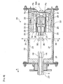
- Fig. 8 is a planar sectional view of a measurement unit that is obtained by unitization of the chamber width measurement device 6 and the in-chamber observation device 7.
- a measurement unit 20 has a casing 22 that has a box shape and thermally insulated by a ceramic heat insulator 21.
- This casing 22 accommodates a CCD camera, a laser displacement sensor, a Peltier element serving as a thermoelectric cooling element, a thermocouple (not shown) used for temperature control, and the like, as to be described later.
- the casing 22 has an end connected with a heat insulated pipe 23, through which cooling air ca is supplied into the casing 22.
- the heat insulated pipe 23 is also provided therein with the cable 9 used for transmission/reception of signals and supply of power.
- This cable 9 is connected with a CCD camera 25, laser displacement sensors 26 and 27, and Peltier element groups 28 and 29.
- the CCD camera 25 is surrounded with heat conductors 30 made of aluminum blocks so as to be in close contact with the CCD camera 25.
- Each of the heat conductors 30 is surrounded with the Peltier element group 28 so as to be in close contact with the corresponding heat conductor 30.
- the Peltier element group 28 is further surrounded with a heat radiation fin group 31.
- the respective Peltier elements configuring the Peltier element group 28 each have a plate shape and are double layered, having heat absorbing surfaces facing the CCD camera 25 and heat radiating surfaces facing the heat radiation fin group 31. In this configuration, the surface temperature of the CCD camera 25 itself can be controlled by the Peltier element group 28 by way of the heat conductors 30.
- the heat-resistant glass plate 32 in front in the photographing direction of the CCD camera 25.
- the heat-resistant glass plate 32 has an inner portion 32a in which an infrared absorbing filter, an infrared reflecting filter, and the heat-resistant glass are combined together with spacers being respectively interposed therebetween.
- a camera unit which has a cooling function and includes the CCD camera 25, the heat conductors 30, the Peltier element group 28, and the heat radiation fin group 31, is accommodated in a heat insulating cylinder 33 that is further accommodated in the casing 22. Accordingly, there is formed a cooling passage Pa between the outer wall of the heat insulating cylinder 33 and the inner wall of the casing 22. There is also formed a cooling passage Pb in a gap between adjacent fins in the heat radiation fin group 31. Streams of cooling air ca having flown through the cooling passages Pb join together at the center of the heat-resistant glass plate 32 and are discharged out of the casing 22.
- the laser displacement sensors 26 and 27 each have a known configuration including a light emitting element and a light receiving element each made of a semiconductor laser and accommodated in a case.
- the laser displacement sensors 26 and 27 emit laser beams in the chamber width direction (along arrows D and E), to partially detect reflected beams with use of the light receiving elements, respectively.
- the laser displacement sensors 26 and 27 are surrounded with heat conductors 34 made of a material same as that for the heat conductors 30 so as to be in close contact with the laser displacement sensors 26 and 27.
- the heat conductors 34 are surrounded with the Peltier element group 29 configured in the same manner as the Peltier element group 28 so as to be in close contact with the heat conductors 34.
- the Peltier element group 29 is further surrounded with the heat radiation fin group 31.
- the laser displacement sensors 26 and 27 are respectively provided with reflecting mirrors 35 and 36 at light emitting ends. These reflecting mirrors 35 and 36 redirect by 90 degrees laser beams T and T, which pass through measurement windows 37 and 38, respectively, to be applied to the chamber wall.
- the chamber width measurement device 6 and the in-chamber observation device 7 thus unitized advantageously realize compact provision of the two devices.
- the present invention is applicable to a management method for the chamber wall of the coke oven of monitoring the camber by measuring chamber width data in the camber and checking the state of the chamber wall.
Landscapes
- Engineering & Computer Science (AREA)
- Chemical & Material Sciences (AREA)
- Physics & Mathematics (AREA)
- General Physics & Mathematics (AREA)
- Materials Engineering (AREA)
- Oil, Petroleum & Natural Gas (AREA)
- Organic Chemistry (AREA)
- Theoretical Computer Science (AREA)
- Computer Vision & Pattern Recognition (AREA)
- Quality & Reliability (AREA)
- Biochemistry (AREA)
- Health & Medical Sciences (AREA)
- Life Sciences & Earth Sciences (AREA)
- Analytical Chemistry (AREA)
- General Health & Medical Sciences (AREA)
- Immunology (AREA)
- Pathology (AREA)
- Geometry (AREA)
- Signal Processing (AREA)
- Multimedia (AREA)
- Waste-Gas Treatment And Other Accessory Devices For Furnaces (AREA)
- Length Measuring Devices By Optical Means (AREA)
- Coke Industry (AREA)
Priority Applications (1)
| Application Number | Priority Date | Filing Date | Title |
|---|---|---|---|
| PL11842518T PL2644682T3 (pl) | 2010-11-26 | 2011-10-14 | Sposób monitorowania wnętrza komory pieca koksowniczego, sposób zarządzania ścianą komory pieca koksowniczego, a także system monitorowania |
Applications Claiming Priority (2)
| Application Number | Priority Date | Filing Date | Title |
|---|---|---|---|
| JP2010263688A JP5676228B2 (ja) | 2010-11-26 | 2010-11-26 | コークス炉炉内監視方法および炉壁管理方法並びに監視システム |
| PCT/JP2011/073725 WO2012070327A1 (ja) | 2010-11-26 | 2011-10-14 | コークス炉炉内監視方法および炉壁管理方法並びに監視システム |
Publications (3)
| Publication Number | Publication Date |
|---|---|
| EP2644682A1 EP2644682A1 (en) | 2013-10-02 |
| EP2644682A4 EP2644682A4 (en) | 2016-03-16 |
| EP2644682B1 true EP2644682B1 (en) | 2019-09-25 |
Family
ID=46145685
Family Applications (1)
| Application Number | Title | Priority Date | Filing Date |
|---|---|---|---|
| EP11842518.0A Active EP2644682B1 (en) | 2010-11-26 | 2011-10-14 | Coke oven monitoring method, furnace wall management method, and monitoring system |
Country Status (8)
| Country | Link |
|---|---|
| US (1) | US9552651B2 (pl) |
| EP (1) | EP2644682B1 (pl) |
| JP (1) | JP5676228B2 (pl) |
| KR (1) | KR101549456B1 (pl) |
| CN (1) | CN103228763B (pl) |
| PL (1) | PL2644682T3 (pl) |
| TW (1) | TWI527894B (pl) |
| WO (1) | WO2012070327A1 (pl) |
Families Citing this family (7)
| Publication number | Priority date | Publication date | Assignee | Title |
|---|---|---|---|---|
| JP6640542B2 (ja) * | 2015-12-07 | 2020-02-05 | 日鉄テックスエンジ株式会社 | 目標芯センサ装置 |
| CN108085024A (zh) * | 2016-11-22 | 2018-05-29 | 上海宝钢工业技术服务有限公司 | 用于焦炉炭化室内墙体的视觉检查装置 |
| TWI731213B (zh) * | 2018-02-01 | 2021-06-21 | 中國鋼鐵股份有限公司 | 外爐效率量化系統 |
| CN110938445A (zh) * | 2019-12-05 | 2020-03-31 | 江苏三希科技股份有限公司 | 一种推焦机工作过程远程监控系统及方法 |
| JP7408488B2 (ja) * | 2020-05-29 | 2024-01-05 | 住友重機械プロセス機器株式会社 | コークス炉撮影装置、コークス炉検査装置、および画像処理装置 |
| CN114540627B (zh) * | 2022-04-01 | 2023-10-27 | 万载志成实业有限公司 | 一种铜泥回收金银的生产方法及装置 |
| CN120848196B (zh) * | 2025-07-22 | 2026-02-03 | 山东三木智慧科技有限公司 | 基于大数据分析的焦炉生产过程智能优化控制系统及方法 |
Family Cites Families (13)
| Publication number | Priority date | Publication date | Assignee | Title |
|---|---|---|---|---|
| JP3042758B2 (ja) | 1995-02-17 | 2000-05-22 | 川崎製鉄株式会社 | コークス炉炭化室の炉壁診断方法および装置 |
| BR9706574A (pt) * | 1996-04-04 | 1999-07-20 | Nippon Steel Corp | Aparelho para a monitoração de superfície de parede |
| JP3924064B2 (ja) * | 1998-03-16 | 2007-06-06 | 新日本製鐵株式会社 | コークス炉炉体診断方法 |
| JP2001003058A (ja) * | 1999-06-16 | 2001-01-09 | Sumitomo Metal Ind Ltd | コークス炉炭化室の壁面検査方法及び壁面検査装置 |
| JP2001040359A (ja) * | 1999-07-28 | 2001-02-13 | Sumitomo Metal Ind Ltd | コークス炉の操業方法 |
| JP3603741B2 (ja) * | 2000-04-11 | 2004-12-22 | 住友金属工業株式会社 | コークス炉の炉壁管理方法 |
| JP5461768B2 (ja) * | 2001-10-09 | 2014-04-02 | 関西熱化学株式会社 | コークス炉炭化室の診断方法 |
| WO2004090071A1 (ja) * | 2003-04-09 | 2004-10-21 | The Kansai Coke And Chemicals Co., Ltd. | コークス炉炭化室の診断装置および診断方法 |
| JP2006036958A (ja) * | 2004-07-28 | 2006-02-09 | Jfe Steel Kk | コークス炉の操業方法 |
| JP4711856B2 (ja) | 2006-02-28 | 2011-06-29 | 関西熱化学株式会社 | 炉幅測定装置およびそれを備えた押出ラム |
| JP2008169274A (ja) * | 2007-01-10 | 2008-07-24 | Jfe Steel Kk | コークス押出ラムの先端位置検出方法及びその先端位置検出装置 |
| EP2113552B1 (en) * | 2007-02-22 | 2017-05-24 | Nippon Steel & Sumitomo Metal Corporation | Coke-oven wall-surface evaluating apparatus, coke-oven wall-surface repair supporting apparatus, coke-oven wall-surface evaluating method, coke-oven wall-surface repair supporting method, and computer program |
| JP5156301B2 (ja) * | 2007-08-31 | 2013-03-06 | 関西熱化学株式会社 | コークス炉の炉壁診断方法 |
-
2010
- 2010-11-26 JP JP2010263688A patent/JP5676228B2/ja active Active
-
2011
- 2011-10-14 EP EP11842518.0A patent/EP2644682B1/en active Active
- 2011-10-14 WO PCT/JP2011/073725 patent/WO2012070327A1/ja not_active Ceased
- 2011-10-14 KR KR1020137010321A patent/KR101549456B1/ko active Active
- 2011-10-14 CN CN201180056992.4A patent/CN103228763B/zh active Active
- 2011-10-14 PL PL11842518T patent/PL2644682T3/pl unknown
- 2011-10-14 US US13/989,707 patent/US9552651B2/en active Active
- 2011-10-25 TW TW100138663A patent/TWI527894B/zh active
Non-Patent Citations (1)
| Title |
|---|
| None * |
Also Published As
| Publication number | Publication date |
|---|---|
| KR101549456B1 (ko) | 2015-09-02 |
| KR20140000228A (ko) | 2014-01-02 |
| JP2012111896A (ja) | 2012-06-14 |
| PL2644682T3 (pl) | 2020-03-31 |
| JP5676228B2 (ja) | 2015-02-25 |
| EP2644682A1 (en) | 2013-10-02 |
| US9552651B2 (en) | 2017-01-24 |
| TW201237156A (en) | 2012-09-16 |
| US20130242081A1 (en) | 2013-09-19 |
| TWI527894B (zh) | 2016-04-01 |
| CN103228763A (zh) | 2013-07-31 |
| CN103228763B (zh) | 2015-06-03 |
| EP2644682A4 (en) | 2016-03-16 |
| WO2012070327A1 (ja) | 2012-05-31 |
Similar Documents
| Publication | Publication Date | Title |
|---|---|---|
| EP2644682B1 (en) | Coke oven monitoring method, furnace wall management method, and monitoring system | |
| CN203337262U (zh) | 一种基于红外技术的在线式成像测温检测系统 | |
| US9804031B2 (en) | Apparatus and method to calculate energy dissipated from an object | |
| CN102829840B (zh) | 一种基于温度检测的间歇搅拌加热装置的料位在线识别系统及方法 | |
| CN105483305B (zh) | 一种基于高炉雷达数据的料层分布可视化方法 | |
| CN111004882B (zh) | 在线测量高炉炉缸炉墙厚度的方法及装置 | |
| CN106872070A (zh) | 一种基于多参量的光纤复合电缆专家诊断系统 | |
| CN115096403B (zh) | 一种基于fbg温度传感器阵列的料位测量系统及方法 | |
| CN115791830A (zh) | 一种钢板检测系统、钢板检测方法及电子设备 | |
| CN103940344A (zh) | 一种高精度远程位移传感器 | |
| CN108759678A (zh) | 散热片尺寸及平整度线上自动测量设备及其测量方法 | |
| CN117387775B (zh) | 电气设备红外测温与无线测温监测系统 | |
| CN103344187A (zh) | 冶金产品宽度的在线测量装置及其方法 | |
| CN112834871B (zh) | 一种高压大长段电缆绝缘故障在线监测系统与方法 | |
| CN111198041A (zh) | 多维度非接触式高精度检测目标温度的装置和方法 | |
| CN103940345B (zh) | 一种远程位移测量系统及方法 | |
| JP2001003058A (ja) | コークス炉炭化室の壁面検査方法及び壁面検査装置 | |
| CN101048654B (zh) | 热分析设备 | |
| KR100355024B1 (ko) | 적설 관측 시스템 | |
| CN117571142A (zh) | 一种曲线斜率预测温度的方法 | |
| RU2677498C1 (ru) | Устройство для контроля состояния воздушных линий электропередачи | |
| CN103230957A (zh) | 检测型材速度的方法及其加工监测系统 | |
| CN121558610A (zh) | 一种基于多热电偶与粒度分析的机械摩擦火花温度测试方法 | |
| CN107367345A (zh) | 一种检测输电线路应力状态的系统 | |
| CN121385032A (zh) | 一种陶瓷内部缺陷检测方法、装置、设备及存储介质 |
Legal Events
| Date | Code | Title | Description |
|---|---|---|---|
| PUAI | Public reference made under article 153(3) epc to a published international application that has entered the european phase |
Free format text: ORIGINAL CODE: 0009012 |
|
| 17P | Request for examination filed |
Effective date: 20130613 |
|
| AK | Designated contracting states |
Kind code of ref document: A1 Designated state(s): AL AT BE BG CH CY CZ DE DK EE ES FI FR GB GR HR HU IE IS IT LI LT LU LV MC MK MT NL NO PL PT RO RS SE SI SK SM TR |
|
| DAX | Request for extension of the european patent (deleted) | ||
| RA4 | Supplementary search report drawn up and despatched (corrected) |
Effective date: 20160212 |
|
| RIC1 | Information provided on ipc code assigned before grant |
Ipc: G06T 7/60 20060101ALI20160208BHEP Ipc: C10B 29/06 20060101AFI20160208BHEP Ipc: G06T 7/00 20060101ALI20160208BHEP Ipc: G01N 21/88 20060101ALI20160208BHEP Ipc: C10B 41/00 20060101ALI20160208BHEP |
|
| STAA | Information on the status of an ep patent application or granted ep patent |
Free format text: STATUS: EXAMINATION IS IN PROGRESS |
|
| 17Q | First examination report despatched |
Effective date: 20180620 |
|
| REG | Reference to a national code |
Ref country code: DE Ref legal event code: R079 Ref document number: 602011062375 Country of ref document: DE Free format text: PREVIOUS MAIN CLASS: C10B0029060000 Ipc: G06T0007000000 |
|
| GRAP | Despatch of communication of intention to grant a patent |
Free format text: ORIGINAL CODE: EPIDOSNIGR1 |
|
| STAA | Information on the status of an ep patent application or granted ep patent |
Free format text: STATUS: GRANT OF PATENT IS INTENDED |
|
| RIC1 | Information provided on ipc code assigned before grant |
Ipc: G06T 7/62 20170101ALI20190405BHEP Ipc: G06T 7/00 20170101AFI20190405BHEP Ipc: G01N 21/88 20060101ALI20190405BHEP Ipc: C10B 45/00 20060101ALI20190405BHEP Ipc: C10B 33/10 20060101ALI20190405BHEP Ipc: C10B 41/00 20060101ALI20190405BHEP Ipc: G01N 21/954 20060101ALI20190405BHEP Ipc: C10B 29/06 20060101ALI20190405BHEP |
|
| INTG | Intention to grant announced |
Effective date: 20190515 |
|
| GRAS | Grant fee paid |
Free format text: ORIGINAL CODE: EPIDOSNIGR3 |
|
| GRAA | (expected) grant |
Free format text: ORIGINAL CODE: 0009210 |
|
| STAA | Information on the status of an ep patent application or granted ep patent |
Free format text: STATUS: THE PATENT HAS BEEN GRANTED |
|
| AK | Designated contracting states |
Kind code of ref document: B1 Designated state(s): AL AT BE BG CH CY CZ DE DK EE ES FI FR GB GR HR HU IE IS IT LI LT LU LV MC MK MT NL NO PL PT RO RS SE SI SK SM TR |
|
| REG | Reference to a national code |
Ref country code: GB Ref legal event code: FG4D |
|
| REG | Reference to a national code |
Ref country code: CH Ref legal event code: EP |
|
| REG | Reference to a national code |
Ref country code: AT Ref legal event code: REF Ref document number: 1184579 Country of ref document: AT Kind code of ref document: T Effective date: 20191015 |
|
| REG | Reference to a national code |
Ref country code: IE Ref legal event code: FG4D |
|
| REG | Reference to a national code |
Ref country code: DE Ref legal event code: R096 Ref document number: 602011062375 Country of ref document: DE |
|
| REG | Reference to a national code |
Ref country code: NL Ref legal event code: MP Effective date: 20190925 |
|
| PG25 | Lapsed in a contracting state [announced via postgrant information from national office to epo] |
Ref country code: SE Free format text: LAPSE BECAUSE OF FAILURE TO SUBMIT A TRANSLATION OF THE DESCRIPTION OR TO PAY THE FEE WITHIN THE PRESCRIBED TIME-LIMIT Effective date: 20190925 Ref country code: NO Free format text: LAPSE BECAUSE OF FAILURE TO SUBMIT A TRANSLATION OF THE DESCRIPTION OR TO PAY THE FEE WITHIN THE PRESCRIBED TIME-LIMIT Effective date: 20191225 Ref country code: FI Free format text: LAPSE BECAUSE OF FAILURE TO SUBMIT A TRANSLATION OF THE DESCRIPTION OR TO PAY THE FEE WITHIN THE PRESCRIBED TIME-LIMIT Effective date: 20190925 Ref country code: BG Free format text: LAPSE BECAUSE OF FAILURE TO SUBMIT A TRANSLATION OF THE DESCRIPTION OR TO PAY THE FEE WITHIN THE PRESCRIBED TIME-LIMIT Effective date: 20191225 Ref country code: HR Free format text: LAPSE BECAUSE OF FAILURE TO SUBMIT A TRANSLATION OF THE DESCRIPTION OR TO PAY THE FEE WITHIN THE PRESCRIBED TIME-LIMIT Effective date: 20190925 Ref country code: LT Free format text: LAPSE BECAUSE OF FAILURE TO SUBMIT A TRANSLATION OF THE DESCRIPTION OR TO PAY THE FEE WITHIN THE PRESCRIBED TIME-LIMIT Effective date: 20190925 |
|
| REG | Reference to a national code |
Ref country code: LT Ref legal event code: MG4D |
|
| PG25 | Lapsed in a contracting state [announced via postgrant information from national office to epo] |
Ref country code: LV Free format text: LAPSE BECAUSE OF FAILURE TO SUBMIT A TRANSLATION OF THE DESCRIPTION OR TO PAY THE FEE WITHIN THE PRESCRIBED TIME-LIMIT Effective date: 20190925 Ref country code: GR Free format text: LAPSE BECAUSE OF FAILURE TO SUBMIT A TRANSLATION OF THE DESCRIPTION OR TO PAY THE FEE WITHIN THE PRESCRIBED TIME-LIMIT Effective date: 20191226 Ref country code: RS Free format text: LAPSE BECAUSE OF FAILURE TO SUBMIT A TRANSLATION OF THE DESCRIPTION OR TO PAY THE FEE WITHIN THE PRESCRIBED TIME-LIMIT Effective date: 20190925 |
|
| REG | Reference to a national code |
Ref country code: AT Ref legal event code: MK05 Ref document number: 1184579 Country of ref document: AT Kind code of ref document: T Effective date: 20190925 |
|
| PG25 | Lapsed in a contracting state [announced via postgrant information from national office to epo] |
Ref country code: PT Free format text: LAPSE BECAUSE OF FAILURE TO SUBMIT A TRANSLATION OF THE DESCRIPTION OR TO PAY THE FEE WITHIN THE PRESCRIBED TIME-LIMIT Effective date: 20200127 Ref country code: AL Free format text: LAPSE BECAUSE OF FAILURE TO SUBMIT A TRANSLATION OF THE DESCRIPTION OR TO PAY THE FEE WITHIN THE PRESCRIBED TIME-LIMIT Effective date: 20190925 Ref country code: EE Free format text: LAPSE BECAUSE OF FAILURE TO SUBMIT A TRANSLATION OF THE DESCRIPTION OR TO PAY THE FEE WITHIN THE PRESCRIBED TIME-LIMIT Effective date: 20190925 Ref country code: NL Free format text: LAPSE BECAUSE OF FAILURE TO SUBMIT A TRANSLATION OF THE DESCRIPTION OR TO PAY THE FEE WITHIN THE PRESCRIBED TIME-LIMIT Effective date: 20190925 Ref country code: ES Free format text: LAPSE BECAUSE OF FAILURE TO SUBMIT A TRANSLATION OF THE DESCRIPTION OR TO PAY THE FEE WITHIN THE PRESCRIBED TIME-LIMIT Effective date: 20190925 Ref country code: RO Free format text: LAPSE BECAUSE OF FAILURE TO SUBMIT A TRANSLATION OF THE DESCRIPTION OR TO PAY THE FEE WITHIN THE PRESCRIBED TIME-LIMIT Effective date: 20190925 Ref country code: AT Free format text: LAPSE BECAUSE OF FAILURE TO SUBMIT A TRANSLATION OF THE DESCRIPTION OR TO PAY THE FEE WITHIN THE PRESCRIBED TIME-LIMIT Effective date: 20190925 |
|
| PG25 | Lapsed in a contracting state [announced via postgrant information from national office to epo] |
Ref country code: IS Free format text: LAPSE BECAUSE OF FAILURE TO SUBMIT A TRANSLATION OF THE DESCRIPTION OR TO PAY THE FEE WITHIN THE PRESCRIBED TIME-LIMIT Effective date: 20200224 Ref country code: CZ Free format text: LAPSE BECAUSE OF FAILURE TO SUBMIT A TRANSLATION OF THE DESCRIPTION OR TO PAY THE FEE WITHIN THE PRESCRIBED TIME-LIMIT Effective date: 20190925 Ref country code: SM Free format text: LAPSE BECAUSE OF FAILURE TO SUBMIT A TRANSLATION OF THE DESCRIPTION OR TO PAY THE FEE WITHIN THE PRESCRIBED TIME-LIMIT Effective date: 20190925 Ref country code: SK Free format text: LAPSE BECAUSE OF FAILURE TO SUBMIT A TRANSLATION OF THE DESCRIPTION OR TO PAY THE FEE WITHIN THE PRESCRIBED TIME-LIMIT Effective date: 20190925 |
|
| REG | Reference to a national code |
Ref country code: CH Ref legal event code: PL |
|
| REG | Reference to a national code |
Ref country code: DE Ref legal event code: R097 Ref document number: 602011062375 Country of ref document: DE |
|
| PG2D | Information on lapse in contracting state deleted |
Ref country code: IS |
|
| PG25 | Lapsed in a contracting state [announced via postgrant information from national office to epo] |
Ref country code: DK Free format text: LAPSE BECAUSE OF FAILURE TO SUBMIT A TRANSLATION OF THE DESCRIPTION OR TO PAY THE FEE WITHIN THE PRESCRIBED TIME-LIMIT Effective date: 20190925 Ref country code: LI Free format text: LAPSE BECAUSE OF NON-PAYMENT OF DUE FEES Effective date: 20191031 Ref country code: LU Free format text: LAPSE BECAUSE OF NON-PAYMENT OF DUE FEES Effective date: 20191014 Ref country code: CH Free format text: LAPSE BECAUSE OF NON-PAYMENT OF DUE FEES Effective date: 20191031 Ref country code: IS Free format text: LAPSE BECAUSE OF FAILURE TO SUBMIT A TRANSLATION OF THE DESCRIPTION OR TO PAY THE FEE WITHIN THE PRESCRIBED TIME-LIMIT Effective date: 20200126 |
|
| PLBE | No opposition filed within time limit |
Free format text: ORIGINAL CODE: 0009261 |
|
| STAA | Information on the status of an ep patent application or granted ep patent |
Free format text: STATUS: NO OPPOSITION FILED WITHIN TIME LIMIT |
|
| REG | Reference to a national code |
Ref country code: BE Ref legal event code: MM Effective date: 20191031 |
|
| PG25 | Lapsed in a contracting state [announced via postgrant information from national office to epo] |
Ref country code: MC Free format text: LAPSE BECAUSE OF FAILURE TO SUBMIT A TRANSLATION OF THE DESCRIPTION OR TO PAY THE FEE WITHIN THE PRESCRIBED TIME-LIMIT Effective date: 20190925 Ref country code: BE Free format text: LAPSE BECAUSE OF NON-PAYMENT OF DUE FEES Effective date: 20191031 |
|
| 26N | No opposition filed |
Effective date: 20200626 |
|
| PG25 | Lapsed in a contracting state [announced via postgrant information from national office to epo] |
Ref country code: IE Free format text: LAPSE BECAUSE OF NON-PAYMENT OF DUE FEES Effective date: 20191014 |
|
| PG25 | Lapsed in a contracting state [announced via postgrant information from national office to epo] |
Ref country code: SI Free format text: LAPSE BECAUSE OF FAILURE TO SUBMIT A TRANSLATION OF THE DESCRIPTION OR TO PAY THE FEE WITHIN THE PRESCRIBED TIME-LIMIT Effective date: 20190925 |
|
| PG25 | Lapsed in a contracting state [announced via postgrant information from national office to epo] |
Ref country code: CY Free format text: LAPSE BECAUSE OF FAILURE TO SUBMIT A TRANSLATION OF THE DESCRIPTION OR TO PAY THE FEE WITHIN THE PRESCRIBED TIME-LIMIT Effective date: 20190925 |
|
| PG25 | Lapsed in a contracting state [announced via postgrant information from national office to epo] |
Ref country code: MT Free format text: LAPSE BECAUSE OF FAILURE TO SUBMIT A TRANSLATION OF THE DESCRIPTION OR TO PAY THE FEE WITHIN THE PRESCRIBED TIME-LIMIT Effective date: 20190925 Ref country code: HU Free format text: LAPSE BECAUSE OF FAILURE TO SUBMIT A TRANSLATION OF THE DESCRIPTION OR TO PAY THE FEE WITHIN THE PRESCRIBED TIME-LIMIT; INVALID AB INITIO Effective date: 20111014 |
|
| PG25 | Lapsed in a contracting state [announced via postgrant information from national office to epo] |
Ref country code: TR Free format text: LAPSE BECAUSE OF FAILURE TO SUBMIT A TRANSLATION OF THE DESCRIPTION OR TO PAY THE FEE WITHIN THE PRESCRIBED TIME-LIMIT Effective date: 20190925 |
|
| PG25 | Lapsed in a contracting state [announced via postgrant information from national office to epo] |
Ref country code: MK Free format text: LAPSE BECAUSE OF FAILURE TO SUBMIT A TRANSLATION OF THE DESCRIPTION OR TO PAY THE FEE WITHIN THE PRESCRIBED TIME-LIMIT Effective date: 20190925 |
|
| PGFP | Annual fee paid to national office [announced via postgrant information from national office to epo] |
Ref country code: GB Payment date: 20240829 Year of fee payment: 14 |
|
| PGFP | Annual fee paid to national office [announced via postgrant information from national office to epo] |
Ref country code: FR Payment date: 20240909 Year of fee payment: 14 |
|
| PGFP | Annual fee paid to national office [announced via postgrant information from national office to epo] |
Ref country code: PL Payment date: 20250915 Year of fee payment: 15 Ref country code: IT Payment date: 20250922 Year of fee payment: 15 |
|
| PGFP | Annual fee paid to national office [announced via postgrant information from national office to epo] |
Ref country code: DE Payment date: 20250902 Year of fee payment: 15 |