EP2644448A1 - Regalsystem - Google Patents
Regalsystem Download PDFInfo
- Publication number
- EP2644448A1 EP2644448A1 EP13160284.9A EP13160284A EP2644448A1 EP 2644448 A1 EP2644448 A1 EP 2644448A1 EP 13160284 A EP13160284 A EP 13160284A EP 2644448 A1 EP2644448 A1 EP 2644448A1
- Authority
- EP
- European Patent Office
- Prior art keywords
- wall
- rail
- vertical rod
- shelving system
- net bottom
- Prior art date
- Legal status (The legal status is an assumption and is not a legal conclusion. Google has not performed a legal analysis and makes no representation as to the accuracy of the status listed.)
- Granted
Links
Images
Classifications
-
- B—PERFORMING OPERATIONS; TRANSPORTING
- B60—VEHICLES IN GENERAL
- B60P—VEHICLES ADAPTED FOR LOAD TRANSPORTATION OR TO TRANSPORT, TO CARRY, OR TO COMPRISE SPECIAL LOADS OR OBJECTS
- B60P3/00—Vehicles adapted to transport, to carry or to comprise special loads or objects
- B60P3/14—Vehicles adapted to transport, to carry or to comprise special loads or objects the object being a workshop for servicing, for maintenance, or for carrying workmen during work
Definitions
- the invention relates to a shelving system according to the preamble of claim 1 and a use thereof.
- a shelf mounting system that is suitable for securing a shelf in a vehicle.
- the shelf comprises at least one linkage and arranged on the linkage, substantially horizontal receiving unit.
- the shelf fastening system further has at least one rail attachable in a vehicle and at least one An engaging member adapted to be releasably engaged with the rail and the linkage.
- a disadvantage of the shelf fastening system described in the prior art is the fact that the items of the shelf fastening system are very bulky and heavy. Once assembled, the shelf-mounting system of the prior art does not provide for it to be constantly adapted, rebuilt or dismantled to the requirements. The attachment of the individual parts together is very complicated and complicated. Even with a complete dismantling, the user faces the problem that the bulky parts inside the vehicle can be difficult to stow, because they are very bulky.
- a shelf for motor vehicles which consists of a storage container and a fastened to the motor vehicle holder.
- the storage container is pivotally mounted and lockable in the holder to prevent falling out of stored in the storage container items while driving and make good use of existing storage space in the vehicle.
- the object of the invention is to provide a shelving system, which is on the one hand weight and space saving and on the other hand offers the user the highest possible flexibility. In this context, especially a simple assembly and disassembly should be possible. In addition, the dismantled parts of the shelving system should take up as little space as possible.
- a shelf system according to the invention for connection to an inner wall of a vehicle is characterized by a vertical bar and a net floor.
- a shelving system different terms are used in parallel.
- the present invention may be referred to as a shelf fastening system or as a shelf.
- the special feature is that the shelf system according to the invention should be suitable for connection to an inner wall of a vehicle.
- the connection with the inner wall of a vehicle should be possible to be redeemed. Releasable in this context means that parts of the shelving system or the entire shelving system should be set manually and without the use of tools on the inner wall of the vehicle and should be able to be released again as needed.
- the inventive inner wall of the vehicle is regularly considered the closed cargo area of a transporter.
- the loading area of a lorry or the storage space of an aircraft can be regarded as the inner wall of a vehicle.
- the shelving system is to be used in the storage space of the vehicle.
- the Shelf system according to the invention is to be used in a van, truck, aircraft or a passenger car.
- the transporter vehicles which are used as courier, express and parcel service vehicles, considered.
- these are vehicles up to 7.5 t, which belong to the so-called Sprinter class.
- the inventive shelving system is very flexible and can be used for a variety of types of vehicles application.
- the shelf system according to the invention consists primarily of a vertical bar and a net floor.
- the network bottom consists of several strand elements, which are superimposed in such a way that a network structure is created.
- the openings in the network structure should be such that conventional parcels, parcels or letters sent in such courier, express service and post office vehicles can not fall through the openings.
- the material of the strand elements depends primarily on the needs of the user. As materials are usually rubber bands, plastic bands, textile bands or braided and thus flexible metal bands into consideration.
- An advantage of the inventive network bottom is the fact that it can be easily rolled up and stowed when not in use.
- a further advantage of the net bottom according to the invention is that the packets inserted into the net bottom usually sink into the net bottom for a few cm, since the strand elements of the net base are designed to be flexible and yielding. As a result, the packets or packages to be transported are no longer on a bare stainless steel plate on which they would have to be additionally secured again, as is the case in the prior art.
- the inventive vertical rod has a detent.
- the vertical rod is also designed in such a way that at the end each comprises a fixing, which is suitable for releasable fastening to a rail.
- the rail in turn is attached to an inner wall.
- one rail is located on a bottom of the inner wall and another rail on a ceiling of the inner wall.
- the floor of the inner wall of the vehicle according to the invention is considered to be the area onto which the user enters when entering the vehicle.
- the ceiling of the inner wall is considered to be the area opposite the floor.
- the rail according to the invention can either be embedded in the floor or the ceiling or be attached to the floor or the ceiling.
- the advantage here is the fact that the fixed to the floor or the ceiling rail of engaging in the rail vertical rod provides a firm footing.
- the rail may be commercially available rails, such as an airline rail or the like. It is easy for the user to connect a corresponding vertical rod releasably fixed to the rail and thereby maintain a secure footing.
- the inner wall may also include the vertical bar.
- the region of the vertical rod, which can make an operative connection with the network base according to the invention, is formed as part of the inner wall.
- the net bottom according to the invention also comprises a connecting element.
- the connecting element is suitable for detachable connection to the vertical rod. This can be explained in detail by a hook-eyelet system happen. But it is also conceivable that another key-lock principle or a quick-release system is used to connect the net bottom through the connecting element with the vertical rod.
- the advantage here is the fact that in a simple and fast way a connection between the net bottom and the vertical rod can be made, which can be canceled as quickly again. The user does not lose time in building the shelving system in the vehicle.
- the net base also comprises a wall connector.
- This wall connector may for example be designed as a piping rail spring groove system, so that the net bottom can be done only by connecting a recessed in the inner wall groove-rail system.
- On the other side of the wall connector of the net bottom in the inventive embodiment comprises the connecting element, which allows a quick and easy connection with the vertical rod.
- an inventive net bottom can be easily transported by the wall connector hanging on the wall. In this way, it requires no additional Verissers the inventive net floor. If necessary, the user can then easily connect the net bottom with a vertical pole erected and thus create a similar construction to a shelf on which in turn packages, packages od. Like. Can be stored.
- the net bottom is designed to be connectable to at least one further vertical rod. This means that the net bottom can be connected in addition to the vertical rod with another vertical rod.
- a full shelf system is created in a quick and easy way that, for example, packages can serve for storage.
- the number of vertical bars, which are connectable to a net floor, depends on the needs of the user and the dimensions available in the vehicle for the construction of a shelving system.
- the vertical rod is connected to the further vertical rod via a transverse stabilizer.
- the cross stabilizer is designed as a rubber band or a metal strut and can be connected to the vertical bar and the further vertical bar in a manner which is discretionary to the person skilled in the art in such a way that it has a stabilizing effect on the overall construction of the shelving system.
- the advantage here is that even with large shelving system structures, a further stabilization of the shelving system can take place.
- a vertical bar is fixed at one end in a rail in a floor.
- the vertical bar is fixed at the end in a rail on a ceiling.
- a net bottom is connected to the inner wall. The net bottom is connected to the vertical bar.
- the order of steps is irrelevant here. It is also conceivable that first the net bottom is connected via the wall connector with an inner wall of the vehicle. Subsequently, then the vertical rod and the other vertical rod can be set up by adjusting and fixing in the rail, and then to connect the network floor at the other end of the wall of the wall connector with a respective connecting element with the vertical rod or the other vertical rod and on this Way to get a shelving system. The degradation takes place in the reverse order.
- An advantage of the shelf system according to the invention is the fact that the mesh panels made of rod elements have a much lower weight than the otherwise usual aluminum shelves. In this context, the cost of production are considerably cheaper and last, the shelf system according to the invention is easier and faster up or degraded.
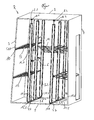
- FIG. 1 shows in detail a side view of a shelf system R according to the invention.
- the inner wall consists of a bottom 1 and a ceiling 2, and a side wall 3 and a further side wall 4.
- six vertical struts 5.1 to 5.6 are in turn partially connected to a transverse stabilizer 6.
- they are connected to a first rail 7.1, 7.2 in the bottom 1 and the other end with a second rail 8.1, 8.2, which is located on the ceiling 2.
- the vertical strut 5.1 is fixed to the fastener 15.1 on the rail 7.1.
- the vertical strut 5.2 is fixed to the first rail 7.1 via a fixing device 15.2 and the vertical strut 5.3 is fixed to the rail 7.1 via a fixing device 15.3.
- the vertical strut 5.4 is fixed to the second rail 7.2 via a fixing 15.4 and the vertical strut 5.5 to the second rail 7.2 via a fixing 15.5 and the vertical strut 5.6 via a fixing 15.6 on the second rail 7.2.
- brackets 15.1 to 15.6 are simple with the respective rails 7.1, 7.2 corresponding Festlegerflves as they are commercially available and in use.
- it can still be seen in the figure how the vertical strut 5.1 is fixed to the rail 8.1 by a fixing 16.1 and the vertical strut to the second rail 8.2 via a fixing 16.2.
- a net bottom 9 via a wall connector 10 which is fixed with a rail on the side wall 3, interacts.
- the net bottom 9 is not connected to connecting elements 12.1 to 12.3 shown in detail with the respective vertical struts 5.1 to 5.3.
- another net bottom 13 is connected to the vertical struts 5.1 to 5.3.
- the net bottom 14 is here clamped obliquely to the vertical struts 5.3, 5.6, so that inlaid packages experience additional security.
Landscapes
- Engineering & Computer Science (AREA)
- Health & Medical Sciences (AREA)
- Public Health (AREA)
- Transportation (AREA)
- Mechanical Engineering (AREA)
- Warehouses Or Storage Devices (AREA)
- Assembled Shelves (AREA)
Abstract
Description
- Die Erfindung betrifft ein Regalsystem nach dem Oberbegriff des Anspruchs 1 und eine Verwendung hierfür.
- Aus dem Stand der Technik sind verschiedene Regalsysteme bekannt. In diesem Zusammenhang wird auf die
DE 10 2007 057 058 A1 verwiesen. Dort ist ein Regalbefestigungssystem beschrieben, das zum Befestigen eines Regals in einem Fahrzeug geeignet ist. Das Regal umfasst zumindest ein Gestänge und eine an dem Gestänge angeordnete, im wesentlichen horizontale Aufnahmeeinheit. Das Regalbefestigungssystem hat ferner zumindest eine in einem Fahrzeug anbringbare Schiene und zumindest ein Eingriffelement, das geeignet ist, mit der Schiene und mit dem Gestänge in lösbarem Eingriff gebracht zu werden. - Nachteilig an dem im Stand der Technik beschriebenen Regalbefestigungssystem ist der Umstand, dass die Einzelteile des Regalbefestigungssystems sehr sperrig und schwer sind. Einmal aufgebaut ist bei dem Regalbefestigungssystem aus dem Stand der Technik nicht vorgesehen, dass es ständig den Erfordernissen angepasst, umgebaut oder abgebaut wird. Die Befestigung der einzelnen Teile miteinander ist sehr umständlich und kompliziert. Selbst bei einem kompletten Abbau steht der Nutzer vor dem Problem, dass die sperrigen Teile im Inneren des Fahrzeugs schwierig verstaut werden können, da sie sehr sperrig sind.
- Ausserdem wird auf die
DE 40 19 011 A1 verwiesen. Dort ist eine Vorrichtung zum Anordnen von Ladegut in einem Laderaum mit vertikal angeordneten, schienenartigen Profilen und Tragstäben, die an diesen Profilen höhenverstellbar montierbar sind, gezeigt. - Ausserdem ist in der
DE 42 15 268 A1 eine Ablage für Kraftfahrzeuge beschrieben, die aus einem Ablagebehälter und einer am Kraftfahrzeug befestigbaren Halterung besteht. Der Ablagebehälter ist in der Halterung schwenkbar und verschliessbar gelagert, um ein Herausfallen von im Ablagebehälter untergebrachten Gegenständen während der Fahrt zu verhindern und den im Kraftfahrzeug vorhandenen Stauraum gut auszunutzen. - Daneben wird ausserdem auf die
WO 92/12026 A1 - Aufgabe der Erfindung ist es, ein Regalsystem zu schaffen, welches zum einen gewichts- und platzsparend ist und zum anderen dem Nutzer eine möglichst hohe Flexibilität bietet. In diesem Zusammenhang soll besonders ein einfacher Auf- und Abbau möglich sein. Ausserdem sollen die abgebauten Teile des Regalsystems möglichst wenig Platz in Anspruch nehmen.
- Zur Lösung der Aufgabe führen die Merkmale des Anspruchs 1.
- Ein erfindungsgemässes Regalsystem zur Verbindung mit einer Innenwandung eines Fahrzeugs ist durch eine Vertikalstange und einen Netzboden gekennzeichnet. Als Regalsystem kommen verschiedene Begrifflichkeiten parallel zur Anwendung. Neben dem Regalsystem ist jetzt auch denkbar, dass die vorliegende Erfindung als Regalbefestigungssystem oder als ein Regal bezeichnet werden kann. Die Besonderheit liegt darin, dass das erfindungsgemässe Regalsystem zur Verbindung mit einer Innenwandung eines Fahrzeugs geeignet sein soll. Die Verbindung mit der Innenwandung eines Fahrzeugs soll dabei wiederlösbar möglich sein. Wiederlösbar bedeutet in diesem Zusammenhang, dass Teile des Regalsystems oder das gesamte Regalsystem manuell und ohne Einsatz von Werkzeugen an der Innenwandung des Fahrzeugs festgelegt und je nach Bedarf wieder gelöst werden können sollen. Als erfindungsgemässe Innenwandung des Fahrzeugs wird regelmässig die geschlossene Ladefläche eines Transporters angesehen. Es ist aber auch denkbar, dass die Ladefläche eines Lastkraftwagens oder der Stauraum eines Luftfahrzeugs als Innenwandung eines Fahrzeugs angesehen werden können. Das Regalsystem soll erfindungsgemäss im Stauraum des Fahrzeugs zur Anwendung kommen. Hierzu soll eine Verbindung mit der Innenwandung des Fahrzeugs im Bereich des Stauraums durchgeführt werden. Das erfindungsgemässe Regalsystem soll in einem Transporter, Lastkraftwagen, einem Luftfahrzeug oder einem Personenkraftwagen verwendet werden. Als Transporter werden die Transporterfahrzeuge, welche als Kurier-, Express- und Paketdienstfahrzeuge genutzt werden, angesehen. In der Regel handelt es sich hierbei um Fahrzeuge bis 7,5 t, welche der sogenannten Sprinter-Klasse angehören. Hier sind aber auch andere Fahrzeuge denkbar, welche für Kurier-, Express- und Paketdienste eingesetzt werden können. Hierbei ist vorteilhaft, dass das erfindungsgemässe Regalsystem sehr flexibel anwendbar ist und für verschiedenste Arten von Fahrzeugen Anwendung finden kann.
- Das erfindungsgemässe Regalsystem besteht in erster Linie aus einer Vertikalstange und einem Netzboden. Der Netzboden besteht aus mehreren Strangelementen, welche derart übereinandergelegt sind, dass eine Netzstruktur entsteht. Die Öffnungen in der Netzstruktur sollen derart vorgesehen sein, dass übliche Pakete, Päckchen oder Briefe, welche in solchen Kurier-, Expressdienst- und Postfahrzeugen versandt werden, nicht durch die Öffnungen fallen können. Das Material der Strangelemente richtet sich in erster Linie nach dem Bedürfnissen des Nutzers. Als Materialien kommen in der Regel Gummibänder, Kunststoffbänder, textile Bänder oder geflochtene und dadurch flexible Metallbänder in Betracht. Vorteilhaft an dem erfindungsgemässen Netzboden ist der Umstand, dass er bei Nicht-Gebrauch einfach zusammengerollt und verstaut werden kann. Sollte der Nutzer aber den Netzboden benötigen, so kann er ihn aus einem verschlossenen Behältnis, beispielsweise im Innern des Fahrzeugs entnehmen und in ein bestehendes Regalsystem als zusätzlichen Regalboden einlegen. Ein weiterer Vorteil des erfindungsgemässen Netzbodens liegt darin, dass die in den Netzboden eingelegten Pakete in der Regel für einige cm in den Netzboden hinein sinken, da die Strangelemente des Netzbodens flexibel und nachgiebig gestaltet sind. Dadurch liegen die zu transportierenden Päckchen bzw. Pakete nicht mehr auf einer blanken Edelstahlplatte, auf der sie nochmals zusätzlich gesichert werden müssten, wie es im Stand der Technik der Fall ist.
- Die erfindungsgemässe Vertikalstange weist eine Rastierung auf. Die Vertikalstange ist ausserdem derart gestaltet, dass sie endseitig jeweils einen Festleger umfasst, welcher geeignet ist zum lösbaren Befestigen an einer Schiene. Die Schiene wiederum ist an einer Innenwandung angebracht. Bevorzugt ist jeweils eine Schiene an einem Boden der Innenwandung befindlich und eine weitere Schiene an einer Decke der Innenwandung. Als Boden der Innenwandung des erfindungsgemässen Fahrzeugs wird der Bereich angesehen, auf den der Nutzer beim Eintreten in das Fahrzeug tritt. Als Decke der Innenwandung wird der entgegen des Bodens befindliche Bereich angesehen. Die erfindungsgemässe Schiene kann hierbei entweder in den Boden oder die Decke eingelassen sein oder an dem Boden bzw. der Decke angebracht sein. Vorteilhaft hierbei ist der Umstand, dass die am Boden bzw. der Decke fest befindliche Schiene der in die Schiene eingreifenden Vertikalstange einen festen Stand bietet. Bei der Schiene kann es sich um handelsübliche Schienen, wie zum Beispiel eine Airline-Schiene oder dergleichen sein. Es ist für den Nutzer einfach, eine entsprechende Vertikalstange wiederlösbar fest mit der Schiene zu verbinden und dadurch einen sicheren Stand zu erhalten.
- In einem weiteren Ausführungsbeispiel kann die Innenwandung die Vertikalstange auch umfassen. Dies bedeutet, dass der Bereich der Vertikalstange, welcher mit dem erfindungsgemässen Netzboden eine Wirkverbindung eingehen kann, als Teil der Innenwandung ausgebildet ist. Vorteilhaft hierbei ist, dass der Nutzer auf einfache und schnelle Weise, lediglich durch Aufstellen zumindest einer weiteren Vertikalstange eine erste Spannmöglichkeit für den zwischen der in der Innenwandung eingelassenen Vertikalstange und der freistehenden Vertikalstange, welche in die erfindungsgemässe Schiene eingreift, ausführen kann.
- Der erfindungsgemässe Netzboden umfasst ausserdem ein Verbindungselement. Das Verbindungselement ist geeignet zur lösbaren Verbindung mit der Vertikalstange. Dies kann im Einzelnen durch ein Haken-Ösen-System geschehen. Es ist aber auch denkbar, dass ein anderes Schlüssel-Schloss-Prinzip oder ein Schnellspannsystem genutzt wird, um den Netzboden durch das Verbindungselement mit der Vertikalstange zu verbinden. Vorteilhaft hierbei ist der Umstand, dass auf einfache und schnelle Weise eine Verbindung zwischen dem Netzboden und der Vertikalstange hergestellt werden kann, die ebenso schnell wieder aufgehoben werden kann. Der Nutzer verliert keine Zeit beim Aufbau des Regalsystems in dem Fahrzeug.
- In einem weiteren erfindungsgemässen Ausführungsbeispiel umfasst der Netzboden ausserdem einen Wandverbinder. Dieser Wandverbinder kann beispielsweise als ein Kederschiene-Federnut-System ausgeführt sein, so dass der Netzboden lediglich durch Verbinden eines in der Innenwandung eingelassenen Nut-Schienen-Systems erfolgen kann. Andernseits des Wandverbinders umfasst der Netzboden im erfindungsgemässen Ausführungsbeispiel das Verbindungselement, welche eine schnelle und einfache Verbindung mit der Vertikalstange zulässt. Auch hier ist vorteilhaft, dass ein einfaches und schnelles Auf- bzw. Abbauen des Regalsystems möglich ist. Bei Nichtnutzung kann ein erfindungsgemässer Netzboden einfach durch den Wandverbinder an der Wand hängend transportiert werden. Auf diese Weise bedarf es keines zusätzlichen Verräumens des erfindungsgemässen Netzbodens. Bei Bedarf kann dann der Nutzer den Netzboden einfach mit einer aufgestellten Vertikalstange verbinden und somit eine einem Regalboden ähnliche Konstruktion schaffen, auf der wiederum Pakete, Päckchen od. dgl. abgelegt werden kann.
- In einem weiteren erfindungsgemässen Ausführungsbeispiel wird der Netzboden mit zumindest einer weiteren Vertikalstange verbindbar ausgeführt. Diese bedeutet, dass der Netzboden neben der Vertikalstange auch mit einer weiteren Vertikalstange verbindbar ist.
- Gerade in dem Ausführungsbeispiel, wenn der Netzboden einends mit einem Wandverbinder ausgestattet ist und mit einer Innenwandung direkt verbunden ist und andernends mit zumindest einer Vertikalstange verbunden ist, entsteht auf schnelle und einfache Weise ein vollwertiges Regalsystem entstanden ist, dass beispielsweise Paketen zur Ablage dienen kann.
- Die Anzahl der Vertikalstangen, welche mit einem Netzboden verbindbar sind, richtet sich nach den Bedürfnissen des Nutzers und den im Fahrzeug zur Verfügung stehenden Maßen für den Aufbau eines Regalsystems.
- In einem anderen Ausführungsbeispiel der Erfindung wird die Vertikalstange mit der weiteren Vertikalstange über einen Querstabilisierer verbunden. Der Querstabilisierer ist als ein Gummiband oder eine Metallstrebe ausgeführt und kann über eine im Ermessen des Fachmanns liegende Art und Weise mit der Vertikalstange und der weiteren Vertikalstange derart verbunden werden, dass sie eine stabilisierende Wirkung auf die Gesamtkonstruktion des Regalsystems hat. Vorteilhaft hierbei ist, dass gerade bei großen Regalsystemaufbauten eine weitere Stabilisierung des Regalsystems erfolgen kann.
- Die erfindungsgemässe Verwendung eines Regalsystems zur Verbindung mit der Innenwandung des Fahrzeugs erfolgt durch folgende Schritte:
- Eine Vertikalstange wird einends in einer Schiene in einem Boden festgelegt. Die Vertikalstange wird andernends in einer Schiene an einer Decke festgelegt. Ein Netzboden wird mit der Innenwandung verbunden. Der Netzboden wird mit der Vertikalstange verbunden.
- Hierbei ist die Reihenfolge der Schritte unerheblich. Es ist auch denkbar, dass zunächst der Netzboden über den Wandverbinder mit einer Innenwandung des Fahrzeugs verbunden wird. Anschliessend können dann die Vertikalstange und die weitere Vertikalstange durch Justieren und Festlegen in der Schiene aufgestellt werden, um dann den Netzboden andernends der Wand des Wandverbinders mit einem jeweils einem Verbindungselement mit der Vertikalstange bzw. der weiteren Vertikalstange zu verbinden und auf diese Weise ein Regalsystem zu erhalten. Der Abbau erfolgt in der umgekehrten Reihenfolge.
- Vorteilhaft an dem erfindungsgemässen Regalsystem ist der Umstand, dass die aus Stangenelementen bestehenden Netzböden ein sehr viel geringeres Gewicht aufweisen, als die sonst üblichen Aluminium-Regale. In diesem Zusammenhang sind auch die Kosten für die Herstellung erheblich günstiger und zuletzt ist das erfindungsgemässe Regalsystem leichter und schneller auf- bzw. abbaubar.
- Weitere Vorteile ergeben sich aus der nachfolgenden Beschreibung der Figur, welche im Einzelnen eine Seitenansicht auf ein erfindungsgemässes Regalsystem R aufzeigt.
- In dem erfindungsgemässen Regelsystem R ist ein Teil einer Innenwandung des nicht gezeigten Fahrzeugs zu erkennen. Die Innenwandung besteht aus einem Boden 1 und einer Decke 2, sowie einer Seitenwandung 3 und einer weiteren Seitenwandung 4. Daneben findet sich eine Mehrzahl von Vertikalstreben 5.1 bis 5.6, welche eine Verbindung zwischen dem Boden 1 und der Decke 2 darstellen. In dem hier gezeigten Ausführungsbeispiel handelt es sich dabei um sechs Vertikalstreben 5.1 bis 5.6. Diese sechs Vertikalstreben 5.1 bis 5.6 sind teilweise wiederum mit einem Querstabilisierer 6 verbunden. Ausserdem sind sie mit einer ersten Schiene 7.1, 7.2 im Boden 1 verbunden und andernends mit einer zweiten Schiene 8.1, 8.2, welche sich an der Decke 2 befindet. Hierbei ist die Vertikalstrebe 5.1 mit dem Festleger 15.1 an der Schiene 7.1 festgelegt. In gleicher Weise ist die Vertikalstrebe 5.2 über einen Festleger 15.2 an der ersten Schiene 7.1 festgelegt und die Vertikalstrebe 5.3 über einen Festleger 15.3 an der Schiene 7.1 festgelegt. In gleicher Weise ist die Vertikalstrebe 5.4 über einen Festleger 15.4 an der zweiten Schiene 7.2 und die Vertikalstrebe 5.5 an der zweiten Schiene 7.2 über einen Festleger 15.5 und die Vertikalstrebe 5.6 über einen Festleger 15.6 an der zweiten Schiene 7.2 festgelegt. Bei den Festlegern 15.1 bis 15.6 handelt es sich um einfache mit den jeweiligen Schienen 7.1, 7.2 korrespondierende Festlegerfüsse, wie sie im Handel erhältlich und gebräuchlich sind. Ausserdem ist in der Figur noch zu erkennen, wie die Vertikalstrebe 5.1 an der Schiene 8.1 durch einen Festleger 16.1 und die Vertikalstrebe an der zweiten Schiene 8.2 über einen Festleger 16.2 festgelegt ist.
- Daneben ist gut zu erkennen, wie ein Netzboden 9 über einen Wandverbinder 10, welcher mit einer Schiene an der Seitenwandung 3 befestigt ist, zusammenwirkt. Andernends des Netzbodens 9 ist der Netzboden 9 nicht mit näher gezeigten Verbindungselementen 12.1 bis 12.3 mit den jeweiligen Vertikalstreben 5.1 bis 5.3 verbunden. In gleicher Weise ist ein weiterer Netzboden 13 mit den Vertikalstreben 5.1 bis 5.3 verbunden. Daneben findet sich auch ein Netzboden 14, welche über nicht näher gezeigte Verbindungselement zwischen den Vertikalstreben 5.2, 5.3 und 5.5, 5.6 gespannt ist. Der Netzboden 14 ist hierbei schräg zu den Vertikalstreben 5.3, 5.6 hin eingespannt, so dass reingelegte Pakete eine zusätzliche Sicherung erfahren.
-
1 Boden 34 67 2 Decke 35 68 3 Seitenwandung 36 69 4 weitere Seitenwandung 37 70 5 Vertikalstrebe 38 71 6 Querstabilisierer 39 72 7 erste Schiene 40 73 8 zweite Schiene 41 74 9 Netzboden 42 75 10 Wandverbinder 43 76 11 Schiene 44 77 12 Verbindungselement 45 78 13 Netzboden 46 79 14 Netzboden 47 15 Festleger 48 R Regalsystem 16 Festleger 49 17 50 18 51 19 52 20 53 21 54 22 55 23 56 24 57 25 58 26 59 27 60 28 61 29 62 30 63 31 64 32 65 33 66
Claims (10)
- Regalsystem zur Verbindung mit einer Innenwandung (1, 2, 3, 4) eines Fahrzeugs
gekennzeichnet durch
eine Vertikalstange (5.1 bis 5.6) und einen Netzboden (9, 13, 14). - Regalsystem nach Anspruch 1, dadurch gekennzeichnet, dass der Netzboden (9, 13, 14) ein Verbindungselement (12.1 bis 12.3) umfasst, geeignet zur lösbaren Verbindung mit der Vertikalstange (5.1 bis 5.6).
- Regalsystem nach Anspruch 1 oder 2, dadurch gekennzeichnet, dass der Netzboden (9, 13, 14) einen Wandverbinder (10) umfasst, geeignet zur lösbaren Verbindung mit der Innenwandung (1, 2, 3, 4).
- Regalsystem nach einem der vorigen Ansprüche, dadurch gekennzeichnet, dass die Vertikalstange (5.1 bis 5.6) jeweils endseitig einen Festleger (15, 16) umfasst, geeignet zum lösbaren Befestigen an einer Schiene (7, 8).
- Regalsystem nach Anspruch 4, dadurch gekennzeichnet, dass die Schiene (7, 8) an einem Boden (1) und/oder an einer Decke (2) der Innenwandung (1, 2, 3, 4) befindlich ist.
- Regalsystem nach einem der vorigen Ansprüche, dadurch gekennzeichnet, dass der Netzboden (9, 13, 14) mit zumindest einer weiteren Vertikalstange (5.1 bis 5.6) verbindbar ist.
- Regalsystem nach Anspruch 6, dadurch gekennzeichnet, dass die Vertikalstange (5.1 bis 5.6) mit der weiteren Vertikalstange (5.1 bis 5.6) über einen Querstabilisierer (6) verbindbar ist.
- Regalsystem nach einem der vorigen Ansprüche, dadurch gekennzeichnet, dass die Innenwandung (1, 2, 3, 4) die Vertikalstange (5.1 bis 5.6) umfasst.
- Verwendung eines Regalsystems nach einem der Ansprüche 1 bis 8 in einem Transporter, Lastkraftwagen, Luftfahrzeug oder Personenkraftwagen.
- Verwendung eines Regalsystems zur Verbindung mit einer Innenwandung (1, 2, 3, 4) eines Fahrzeugs gekennzeichnet durch folgende Schritte:- eine Vertikalstange (5.1 bis 5.6) wird einends in einer Schiene (7) in einem Boden (1) festgelegt,- die Vertikalstange (5.1 bis 5.6) wird andernends in einer Schiene (8) an einer Decke (2) festgelegt,- ein Netzboden (9, 13, 14) wird mit der Seitenwandung (3, 4) verbunden,- der Netzboden (9, 13, 14) wird mit der Vertikalstange (5.1 bis 5.6) verbunden.
Applications Claiming Priority (1)
| Application Number | Priority Date | Filing Date | Title |
|---|---|---|---|
| DE201210102612 DE102012102612A1 (de) | 2012-03-27 | 2012-03-27 | Regalsystem |
Publications (2)
| Publication Number | Publication Date |
|---|---|
| EP2644448A1 true EP2644448A1 (de) | 2013-10-02 |
| EP2644448B1 EP2644448B1 (de) | 2018-11-28 |
Family
ID=47915511
Family Applications (1)
| Application Number | Title | Priority Date | Filing Date |
|---|---|---|---|
| EP13160284.9A Active EP2644448B1 (de) | 2012-03-27 | 2013-03-21 | Regalsystem |
Country Status (2)
| Country | Link |
|---|---|
| EP (1) | EP2644448B1 (de) |
| DE (1) | DE102012102612A1 (de) |
Citations (7)
| Publication number | Priority date | Publication date | Assignee | Title |
|---|---|---|---|---|
| DE1964772A1 (de) * | 1969-12-24 | 1971-07-15 | Waggon Und Maschb Ag Donauwoer | Vorrichtung zum Verzurren einer Ladung |
| DE4019011A1 (de) | 1990-06-13 | 1991-12-19 | Jungfalk Ancra Gmbh | Vorrichtung zum anordnen von ladegut in einem laderaum |
| WO1992012026A1 (en) | 1991-01-07 | 1992-07-23 | Pohjolan Kuljetuskaluste Oy | Shelf system for use in delivery vans |
| DE4215268A1 (de) | 1992-05-09 | 1993-11-11 | Grabbe Klaus | Umsetzvorrichtung mit variabler Werkzeugbestückung für die Bearbeitung fester Stoffgemenge in offenen und geschlossenen Systemen |
| EP1736364A1 (de) * | 2005-06-24 | 2006-12-27 | BOS GmbH & Co. KG | Laderaumfunktionsvorrichtung für ein Kraftfahrzeug |
| DE102007057058A1 (de) | 2007-11-27 | 2009-05-28 | Daimler Ag | Regalbefestigungssystem zum Befestigen eines Regals in einem Fahrzeug |
| DE102010037716A1 (de) * | 2010-09-22 | 2012-03-22 | Allsafe Jungfalk Gmbh & Co. Kg | Vorrichtung zum Sichern von Ladegut auf einer Ladefläche |
-
2012
- 2012-03-27 DE DE201210102612 patent/DE102012102612A1/de not_active Withdrawn
-
2013
- 2013-03-21 EP EP13160284.9A patent/EP2644448B1/de active Active
Patent Citations (7)
| Publication number | Priority date | Publication date | Assignee | Title |
|---|---|---|---|---|
| DE1964772A1 (de) * | 1969-12-24 | 1971-07-15 | Waggon Und Maschb Ag Donauwoer | Vorrichtung zum Verzurren einer Ladung |
| DE4019011A1 (de) | 1990-06-13 | 1991-12-19 | Jungfalk Ancra Gmbh | Vorrichtung zum anordnen von ladegut in einem laderaum |
| WO1992012026A1 (en) | 1991-01-07 | 1992-07-23 | Pohjolan Kuljetuskaluste Oy | Shelf system for use in delivery vans |
| DE4215268A1 (de) | 1992-05-09 | 1993-11-11 | Grabbe Klaus | Umsetzvorrichtung mit variabler Werkzeugbestückung für die Bearbeitung fester Stoffgemenge in offenen und geschlossenen Systemen |
| EP1736364A1 (de) * | 2005-06-24 | 2006-12-27 | BOS GmbH & Co. KG | Laderaumfunktionsvorrichtung für ein Kraftfahrzeug |
| DE102007057058A1 (de) | 2007-11-27 | 2009-05-28 | Daimler Ag | Regalbefestigungssystem zum Befestigen eines Regals in einem Fahrzeug |
| DE102010037716A1 (de) * | 2010-09-22 | 2012-03-22 | Allsafe Jungfalk Gmbh & Co. Kg | Vorrichtung zum Sichern von Ladegut auf einer Ladefläche |
Also Published As
| Publication number | Publication date |
|---|---|
| EP2644448B1 (de) | 2018-11-28 |
| DE102012102612A1 (de) | 2013-10-02 |
Similar Documents
| Publication | Publication Date | Title |
|---|---|---|
| DE202010011418U1 (de) | Rucksack mit variabler Schultergurtbefestigung | |
| DE202015104324U1 (de) | an einer Seitenwand angeordnetes verstellbares Schienensystem für Fracht | |
| DE102015005296A1 (de) | Kraftfahrzeugsitzanordnung | |
| DE102012014232A1 (de) | Anordnung zur Ladungssicherung | |
| DE102007057058B4 (de) | Regalbefestigungssystem zum Befestigen eines Regals in einem Fahrzeug | |
| EP2644448B1 (de) | Regalsystem | |
| EP2945828A1 (de) | Montagevorrichtung für ein seitenwandverkleidungselement eines schienenfahrzeugs | |
| DE202014100471U1 (de) | Schuhregal | |
| DE102016015092A1 (de) | Personenbegehbares, raumflexibles Containersystem | |
| EP3290309B1 (de) | Fahrrad-ausstellungsständer | |
| DE102017212408B3 (de) | Klappsitz | |
| DE202013103414U1 (de) | Dachträger für ein Kraftfahrzeug | |
| DE102016108827A1 (de) | Nutzfahrzeugaufbau | |
| DE102016223169B4 (de) | Schienenfahrzeug mit Fahrgasttisch | |
| DE102014105150A1 (de) | Zaun sowie Überwachungsvorrichtung | |
| EP2781410B1 (de) | Campingtisch | |
| EP3718849B1 (de) | Schienenfahrzeug und verwendung | |
| AT15472U1 (de) | Innenausrüstungssystem für Rettungsfahrzeuge | |
| AT509036B1 (de) | Nackenstütze für wärmebehandlungsanlagen, insbesondere saunen, infrarot- oder wärmekabinen | |
| DE202010014696U1 (de) | Windschott | |
| DE102015121678B4 (de) | Trägerkonstruktion zum Transport von Gegenständen | |
| DE102017125972A1 (de) | Wechsel-Innenausbaueinheit, Baukasten zum Erstellen einer solchen Einheit, Verfahren zum Ausstatten eines Lastkraftwagens mit einer Wechsel-Innenausbaueinheit | |
| DE102013112955A1 (de) | Laderaumaufteilungssystem für Transportfahrzeuge, insbesondere für Kühlfahrzeuge | |
| DE102010036320B4 (de) | Innenausbau eines Bestattungsfahrzeugs | |
| DE102010026493B4 (de) | Halterungssystem, insbesondere für Kraftfahrzeuge |
Legal Events
| Date | Code | Title | Description |
|---|---|---|---|
| PUAI | Public reference made under article 153(3) epc to a published international application that has entered the european phase |
Free format text: ORIGINAL CODE: 0009012 |
|
| AK | Designated contracting states |
Kind code of ref document: A1 Designated state(s): AL AT BE BG CH CY CZ DE DK EE ES FI FR GB GR HR HU IE IS IT LI LT LU LV MC MK MT NL NO PL PT RO RS SE SI SK SM TR |
|
| AX | Request for extension of the european patent |
Extension state: BA ME |
|
| 17P | Request for examination filed |
Effective date: 20140401 |
|
| RBV | Designated contracting states (corrected) |
Designated state(s): AL AT BE BG CH CY CZ DE DK EE ES FI FR GB GR HR HU IE IS IT LI LT LU LV MC MK MT NL NO PL PT RO RS SE SI SK SM TR |
|
| RAP1 | Party data changed (applicant data changed or rights of an application transferred) |
Owner name: ALLSAFE GMBH & CO. KG |
|
| STAA | Information on the status of an ep patent application or granted ep patent |
Free format text: STATUS: EXAMINATION IS IN PROGRESS |
|
| 17Q | First examination report despatched |
Effective date: 20171026 |
|
| GRAP | Despatch of communication of intention to grant a patent |
Free format text: ORIGINAL CODE: EPIDOSNIGR1 |
|
| STAA | Information on the status of an ep patent application or granted ep patent |
Free format text: STATUS: GRANT OF PATENT IS INTENDED |
|
| INTG | Intention to grant announced |
Effective date: 20180711 |
|
| GRAS | Grant fee paid |
Free format text: ORIGINAL CODE: EPIDOSNIGR3 |
|
| GRAA | (expected) grant |
Free format text: ORIGINAL CODE: 0009210 |
|
| STAA | Information on the status of an ep patent application or granted ep patent |
Free format text: STATUS: THE PATENT HAS BEEN GRANTED |
|
| AK | Designated contracting states |
Kind code of ref document: B1 Designated state(s): AL AT BE BG CH CY CZ DE DK EE ES FI FR GB GR HR HU IE IS IT LI LT LU LV MC MK MT NL NO PL PT RO RS SE SI SK SM TR |
|
| REG | Reference to a national code |
Ref country code: GB Ref legal event code: FG4D Free format text: NOT ENGLISH |
|
| REG | Reference to a national code |
Ref country code: CH Ref legal event code: EP |
|
| REG | Reference to a national code |
Ref country code: AT Ref legal event code: REF Ref document number: 1069827 Country of ref document: AT Kind code of ref document: T Effective date: 20181215 |
|
| REG | Reference to a national code |
Ref country code: DE Ref legal event code: R096 Ref document number: 502013011695 Country of ref document: DE |
|
| REG | Reference to a national code |
Ref country code: IE Ref legal event code: FG4D Free format text: LANGUAGE OF EP DOCUMENT: GERMAN |
|
| REG | Reference to a national code |
Ref country code: NL Ref legal event code: MP Effective date: 20181128 |
|
| REG | Reference to a national code |
Ref country code: LT Ref legal event code: MG4D |
|
| PG25 | Lapsed in a contracting state [announced via postgrant information from national office to epo] |
Ref country code: IS Free format text: LAPSE BECAUSE OF FAILURE TO SUBMIT A TRANSLATION OF THE DESCRIPTION OR TO PAY THE FEE WITHIN THE PRESCRIBED TIME-LIMIT Effective date: 20190328 Ref country code: FI Free format text: LAPSE BECAUSE OF FAILURE TO SUBMIT A TRANSLATION OF THE DESCRIPTION OR TO PAY THE FEE WITHIN THE PRESCRIBED TIME-LIMIT Effective date: 20181128 Ref country code: BG Free format text: LAPSE BECAUSE OF FAILURE TO SUBMIT A TRANSLATION OF THE DESCRIPTION OR TO PAY THE FEE WITHIN THE PRESCRIBED TIME-LIMIT Effective date: 20190228 Ref country code: HR Free format text: LAPSE BECAUSE OF FAILURE TO SUBMIT A TRANSLATION OF THE DESCRIPTION OR TO PAY THE FEE WITHIN THE PRESCRIBED TIME-LIMIT Effective date: 20181128 Ref country code: LV Free format text: LAPSE BECAUSE OF FAILURE TO SUBMIT A TRANSLATION OF THE DESCRIPTION OR TO PAY THE FEE WITHIN THE PRESCRIBED TIME-LIMIT Effective date: 20181128 Ref country code: ES Free format text: LAPSE BECAUSE OF FAILURE TO SUBMIT A TRANSLATION OF THE DESCRIPTION OR TO PAY THE FEE WITHIN THE PRESCRIBED TIME-LIMIT Effective date: 20181128 Ref country code: LT Free format text: LAPSE BECAUSE OF FAILURE TO SUBMIT A TRANSLATION OF THE DESCRIPTION OR TO PAY THE FEE WITHIN THE PRESCRIBED TIME-LIMIT Effective date: 20181128 Ref country code: NO Free format text: LAPSE BECAUSE OF FAILURE TO SUBMIT A TRANSLATION OF THE DESCRIPTION OR TO PAY THE FEE WITHIN THE PRESCRIBED TIME-LIMIT Effective date: 20190228 |
|
| PG25 | Lapsed in a contracting state [announced via postgrant information from national office to epo] |
Ref country code: GR Free format text: LAPSE BECAUSE OF FAILURE TO SUBMIT A TRANSLATION OF THE DESCRIPTION OR TO PAY THE FEE WITHIN THE PRESCRIBED TIME-LIMIT Effective date: 20190301 Ref country code: PT Free format text: LAPSE BECAUSE OF FAILURE TO SUBMIT A TRANSLATION OF THE DESCRIPTION OR TO PAY THE FEE WITHIN THE PRESCRIBED TIME-LIMIT Effective date: 20190328 Ref country code: RS Free format text: LAPSE BECAUSE OF FAILURE TO SUBMIT A TRANSLATION OF THE DESCRIPTION OR TO PAY THE FEE WITHIN THE PRESCRIBED TIME-LIMIT Effective date: 20181128 Ref country code: AL Free format text: LAPSE BECAUSE OF FAILURE TO SUBMIT A TRANSLATION OF THE DESCRIPTION OR TO PAY THE FEE WITHIN THE PRESCRIBED TIME-LIMIT Effective date: 20181128 Ref country code: SE Free format text: LAPSE BECAUSE OF FAILURE TO SUBMIT A TRANSLATION OF THE DESCRIPTION OR TO PAY THE FEE WITHIN THE PRESCRIBED TIME-LIMIT Effective date: 20181128 |
|
| PG25 | Lapsed in a contracting state [announced via postgrant information from national office to epo] |
Ref country code: NL Free format text: LAPSE BECAUSE OF FAILURE TO SUBMIT A TRANSLATION OF THE DESCRIPTION OR TO PAY THE FEE WITHIN THE PRESCRIBED TIME-LIMIT Effective date: 20181128 |
|
| PG25 | Lapsed in a contracting state [announced via postgrant information from national office to epo] |
Ref country code: IT Free format text: LAPSE BECAUSE OF FAILURE TO SUBMIT A TRANSLATION OF THE DESCRIPTION OR TO PAY THE FEE WITHIN THE PRESCRIBED TIME-LIMIT Effective date: 20181128 Ref country code: CZ Free format text: LAPSE BECAUSE OF FAILURE TO SUBMIT A TRANSLATION OF THE DESCRIPTION OR TO PAY THE FEE WITHIN THE PRESCRIBED TIME-LIMIT Effective date: 20181128 Ref country code: DK Free format text: LAPSE BECAUSE OF FAILURE TO SUBMIT A TRANSLATION OF THE DESCRIPTION OR TO PAY THE FEE WITHIN THE PRESCRIBED TIME-LIMIT Effective date: 20181128 Ref country code: PL Free format text: LAPSE BECAUSE OF FAILURE TO SUBMIT A TRANSLATION OF THE DESCRIPTION OR TO PAY THE FEE WITHIN THE PRESCRIBED TIME-LIMIT Effective date: 20181128 |
|
| REG | Reference to a national code |
Ref country code: DE Ref legal event code: R097 Ref document number: 502013011695 Country of ref document: DE |
|
| PG25 | Lapsed in a contracting state [announced via postgrant information from national office to epo] |
Ref country code: EE Free format text: LAPSE BECAUSE OF FAILURE TO SUBMIT A TRANSLATION OF THE DESCRIPTION OR TO PAY THE FEE WITHIN THE PRESCRIBED TIME-LIMIT Effective date: 20181128 Ref country code: RO Free format text: LAPSE BECAUSE OF FAILURE TO SUBMIT A TRANSLATION OF THE DESCRIPTION OR TO PAY THE FEE WITHIN THE PRESCRIBED TIME-LIMIT Effective date: 20181128 Ref country code: SK Free format text: LAPSE BECAUSE OF FAILURE TO SUBMIT A TRANSLATION OF THE DESCRIPTION OR TO PAY THE FEE WITHIN THE PRESCRIBED TIME-LIMIT Effective date: 20181128 Ref country code: SM Free format text: LAPSE BECAUSE OF FAILURE TO SUBMIT A TRANSLATION OF THE DESCRIPTION OR TO PAY THE FEE WITHIN THE PRESCRIBED TIME-LIMIT Effective date: 20181128 |
|
| PLBE | No opposition filed within time limit |
Free format text: ORIGINAL CODE: 0009261 |
|
| STAA | Information on the status of an ep patent application or granted ep patent |
Free format text: STATUS: NO OPPOSITION FILED WITHIN TIME LIMIT |
|
| PG25 | Lapsed in a contracting state [announced via postgrant information from national office to epo] |
Ref country code: MC Free format text: LAPSE BECAUSE OF FAILURE TO SUBMIT A TRANSLATION OF THE DESCRIPTION OR TO PAY THE FEE WITHIN THE PRESCRIBED TIME-LIMIT Effective date: 20181128 Ref country code: SI Free format text: LAPSE BECAUSE OF FAILURE TO SUBMIT A TRANSLATION OF THE DESCRIPTION OR TO PAY THE FEE WITHIN THE PRESCRIBED TIME-LIMIT Effective date: 20181128 |
|
| REG | Reference to a national code |
Ref country code: CH Ref legal event code: PL |
|
| 26N | No opposition filed |
Effective date: 20190829 |
|
| GBPC | Gb: european patent ceased through non-payment of renewal fee |
Effective date: 20190321 |
|
| PG25 | Lapsed in a contracting state [announced via postgrant information from national office to epo] |
Ref country code: LU Free format text: LAPSE BECAUSE OF NON-PAYMENT OF DUE FEES Effective date: 20190321 |
|
| REG | Reference to a national code |
Ref country code: BE Ref legal event code: MM Effective date: 20190331 |
|
| PG25 | Lapsed in a contracting state [announced via postgrant information from national office to epo] |
Ref country code: IE Free format text: LAPSE BECAUSE OF NON-PAYMENT OF DUE FEES Effective date: 20190321 Ref country code: GB Free format text: LAPSE BECAUSE OF NON-PAYMENT OF DUE FEES Effective date: 20190321 Ref country code: CH Free format text: LAPSE BECAUSE OF NON-PAYMENT OF DUE FEES Effective date: 20190331 Ref country code: LI Free format text: LAPSE BECAUSE OF NON-PAYMENT OF DUE FEES Effective date: 20190331 |
|
| PG25 | Lapsed in a contracting state [announced via postgrant information from national office to epo] |
Ref country code: FR Free format text: LAPSE BECAUSE OF NON-PAYMENT OF DUE FEES Effective date: 20190331 Ref country code: BE Free format text: LAPSE BECAUSE OF NON-PAYMENT OF DUE FEES Effective date: 20190331 |
|
| PG25 | Lapsed in a contracting state [announced via postgrant information from national office to epo] |
Ref country code: TR Free format text: LAPSE BECAUSE OF FAILURE TO SUBMIT A TRANSLATION OF THE DESCRIPTION OR TO PAY THE FEE WITHIN THE PRESCRIBED TIME-LIMIT Effective date: 20181128 |
|
| PG25 | Lapsed in a contracting state [announced via postgrant information from national office to epo] |
Ref country code: MT Free format text: LAPSE BECAUSE OF FAILURE TO SUBMIT A TRANSLATION OF THE DESCRIPTION OR TO PAY THE FEE WITHIN THE PRESCRIBED TIME-LIMIT Effective date: 20181128 |
|
| REG | Reference to a national code |
Ref country code: AT Ref legal event code: MM01 Ref document number: 1069827 Country of ref document: AT Kind code of ref document: T Effective date: 20190321 |
|
| PG25 | Lapsed in a contracting state [announced via postgrant information from national office to epo] |
Ref country code: AT Free format text: LAPSE BECAUSE OF NON-PAYMENT OF DUE FEES Effective date: 20190321 |
|
| PG25 | Lapsed in a contracting state [announced via postgrant information from national office to epo] |
Ref country code: CY Free format text: LAPSE BECAUSE OF FAILURE TO SUBMIT A TRANSLATION OF THE DESCRIPTION OR TO PAY THE FEE WITHIN THE PRESCRIBED TIME-LIMIT Effective date: 20181128 |
|
| PG25 | Lapsed in a contracting state [announced via postgrant information from national office to epo] |
Ref country code: HU Free format text: LAPSE BECAUSE OF FAILURE TO SUBMIT A TRANSLATION OF THE DESCRIPTION OR TO PAY THE FEE WITHIN THE PRESCRIBED TIME-LIMIT; INVALID AB INITIO Effective date: 20130321 |
|
| PG25 | Lapsed in a contracting state [announced via postgrant information from national office to epo] |
Ref country code: MK Free format text: LAPSE BECAUSE OF FAILURE TO SUBMIT A TRANSLATION OF THE DESCRIPTION OR TO PAY THE FEE WITHIN THE PRESCRIBED TIME-LIMIT Effective date: 20181128 |
|
| P01 | Opt-out of the competence of the unified patent court (upc) registered |
Effective date: 20230530 |
|
| PGFP | Annual fee paid to national office [announced via postgrant information from national office to epo] |
Ref country code: DE Payment date: 20250527 Year of fee payment: 13 |