EP2643569B1 - Silencer - Google Patents
Silencer Download PDFInfo
- Publication number
- EP2643569B1 EP2643569B1 EP11776805.1A EP11776805A EP2643569B1 EP 2643569 B1 EP2643569 B1 EP 2643569B1 EP 11776805 A EP11776805 A EP 11776805A EP 2643569 B1 EP2643569 B1 EP 2643569B1
- Authority
- EP
- European Patent Office
- Prior art keywords
- collar
- bracket
- shells
- silencer according
- hollow body
- Prior art date
- Legal status (The legal status is an assumption and is not a legal conclusion. Google has not performed a legal analysis and makes no representation as to the accuracy of the status listed.)
- Active
Links
- 230000003584 silencer Effects 0.000 title claims description 19
- 238000010276 construction Methods 0.000 claims description 7
- 238000000034 method Methods 0.000 claims description 6
- 230000000295 complement effect Effects 0.000 claims description 5
- 238000002485 combustion reaction Methods 0.000 claims description 4
- 238000004049 embossing Methods 0.000 claims description 3
- 239000007789 gas Substances 0.000 description 19
- 238000004519 manufacturing process Methods 0.000 description 4
- 238000005520 cutting process Methods 0.000 description 3
- 238000003780 insertion Methods 0.000 description 3
- 230000037431 insertion Effects 0.000 description 3
- 238000004080 punching Methods 0.000 description 3
- 238000010521 absorption reaction Methods 0.000 description 2
- 230000001419 dependent effect Effects 0.000 description 2
- 230000000694 effects Effects 0.000 description 2
- 230000001747 exhibiting effect Effects 0.000 description 2
- 239000002184 metal Substances 0.000 description 2
- 230000008878 coupling Effects 0.000 description 1
- 238000010168 coupling process Methods 0.000 description 1
- 238000005859 coupling reaction Methods 0.000 description 1
- 238000013016 damping Methods 0.000 description 1
- 238000007599 discharging Methods 0.000 description 1
- 238000002955 isolation Methods 0.000 description 1
- 230000003068 static effect Effects 0.000 description 1
- 238000004804 winding Methods 0.000 description 1
Images


Classifications
-
- F—MECHANICAL ENGINEERING; LIGHTING; HEATING; WEAPONS; BLASTING
- F16—ENGINEERING ELEMENTS AND UNITS; GENERAL MEASURES FOR PRODUCING AND MAINTAINING EFFECTIVE FUNCTIONING OF MACHINES OR INSTALLATIONS; THERMAL INSULATION IN GENERAL
- F16B—DEVICES FOR FASTENING OR SECURING CONSTRUCTIONAL ELEMENTS OR MACHINE PARTS TOGETHER, e.g. NAILS, BOLTS, CIRCLIPS, CLAMPS, CLIPS OR WEDGES; JOINTS OR JOINTING
- F16B5/00—Joining sheets or plates, e.g. panels, to one another or to strips or bars parallel to them
- F16B5/07—Joining sheets or plates, e.g. panels, to one another or to strips or bars parallel to them by means of multiple interengaging protrusions on the surfaces, e.g. hooks, coils
-
- F—MECHANICAL ENGINEERING; LIGHTING; HEATING; WEAPONS; BLASTING
- F01—MACHINES OR ENGINES IN GENERAL; ENGINE PLANTS IN GENERAL; STEAM ENGINES
- F01N—GAS-FLOW SILENCERS OR EXHAUST APPARATUS FOR MACHINES OR ENGINES IN GENERAL; GAS-FLOW SILENCERS OR EXHAUST APPARATUS FOR INTERNAL COMBUSTION ENGINES
- F01N13/00—Exhaust or silencing apparatus characterised by constructional features ; Exhaust or silencing apparatus, or parts thereof, having pertinent characteristics not provided for in, or of interest apart from, groups F01N1/00 - F01N5/00, F01N9/00, F01N11/00
- F01N13/18—Construction facilitating manufacture, assembly, or disassembly
- F01N13/1838—Construction facilitating manufacture, assembly, or disassembly characterised by the type of connection between parts of exhaust or silencing apparatus, e.g. between housing and tubes, between tubes and baffles
-
- F—MECHANICAL ENGINEERING; LIGHTING; HEATING; WEAPONS; BLASTING
- F01—MACHINES OR ENGINES IN GENERAL; ENGINE PLANTS IN GENERAL; STEAM ENGINES
- F01N—GAS-FLOW SILENCERS OR EXHAUST APPARATUS FOR MACHINES OR ENGINES IN GENERAL; GAS-FLOW SILENCERS OR EXHAUST APPARATUS FOR INTERNAL COMBUSTION ENGINES
- F01N1/00—Silencing apparatus characterised by method of silencing
- F01N1/06—Silencing apparatus characterised by method of silencing by using interference effect
-
- F—MECHANICAL ENGINEERING; LIGHTING; HEATING; WEAPONS; BLASTING
- F01—MACHINES OR ENGINES IN GENERAL; ENGINE PLANTS IN GENERAL; STEAM ENGINES
- F01N—GAS-FLOW SILENCERS OR EXHAUST APPARATUS FOR MACHINES OR ENGINES IN GENERAL; GAS-FLOW SILENCERS OR EXHAUST APPARATUS FOR INTERNAL COMBUSTION ENGINES
- F01N13/00—Exhaust or silencing apparatus characterised by constructional features ; Exhaust or silencing apparatus, or parts thereof, having pertinent characteristics not provided for in, or of interest apart from, groups F01N1/00 - F01N5/00, F01N9/00, F01N11/00
- F01N13/18—Construction facilitating manufacture, assembly, or disassembly
- F01N13/1872—Construction facilitating manufacture, assembly, or disassembly the assembly using stamp-formed parts or otherwise deformed sheet-metal
-
- F—MECHANICAL ENGINEERING; LIGHTING; HEATING; WEAPONS; BLASTING
- F01—MACHINES OR ENGINES IN GENERAL; ENGINE PLANTS IN GENERAL; STEAM ENGINES
- F01N—GAS-FLOW SILENCERS OR EXHAUST APPARATUS FOR MACHINES OR ENGINES IN GENERAL; GAS-FLOW SILENCERS OR EXHAUST APPARATUS FOR INTERNAL COMBUSTION ENGINES
- F01N2450/00—Methods or apparatus for fitting, inserting or repairing different elements
- F01N2450/18—Methods or apparatus for fitting, inserting or repairing different elements by using quick-active type locking mechanisms, e.g. clips
-
- F—MECHANICAL ENGINEERING; LIGHTING; HEATING; WEAPONS; BLASTING
- F01—MACHINES OR ENGINES IN GENERAL; ENGINE PLANTS IN GENERAL; STEAM ENGINES
- F01N—GAS-FLOW SILENCERS OR EXHAUST APPARATUS FOR MACHINES OR ENGINES IN GENERAL; GAS-FLOW SILENCERS OR EXHAUST APPARATUS FOR INTERNAL COMBUSTION ENGINES
- F01N2450/00—Methods or apparatus for fitting, inserting or repairing different elements
- F01N2450/20—Methods or apparatus for fitting, inserting or repairing different elements by mechanical joints, e.g. by deforming housing, tube, baffle plate or parts thereof
-
- F—MECHANICAL ENGINEERING; LIGHTING; HEATING; WEAPONS; BLASTING
- F01—MACHINES OR ENGINES IN GENERAL; ENGINE PLANTS IN GENERAL; STEAM ENGINES
- F01N—GAS-FLOW SILENCERS OR EXHAUST APPARATUS FOR MACHINES OR ENGINES IN GENERAL; GAS-FLOW SILENCERS OR EXHAUST APPARATUS FOR INTERNAL COMBUSTION ENGINES
- F01N2450/00—Methods or apparatus for fitting, inserting or repairing different elements
- F01N2450/26—Methods or apparatus for fitting, inserting or repairing different elements by bayonet fittings
-
- F—MECHANICAL ENGINEERING; LIGHTING; HEATING; WEAPONS; BLASTING
- F01—MACHINES OR ENGINES IN GENERAL; ENGINE PLANTS IN GENERAL; STEAM ENGINES
- F01N—GAS-FLOW SILENCERS OR EXHAUST APPARATUS FOR MACHINES OR ENGINES IN GENERAL; GAS-FLOW SILENCERS OR EXHAUST APPARATUS FOR INTERNAL COMBUSTION ENGINES
- F01N2470/00—Structure or shape of gas passages, pipes or tubes
- F01N2470/06—Tubes being formed by assembly of stamped or otherwise deformed sheet-metal
Definitions
- the present invention relates to a silencer for an exhaust system of an internal combustion engine, in particular of a motor vehicle, having the features of the preamble of claim 1.
- a muffler comprises a muffler housing, which encloses a housing interior, wherein in the housing interior at least one exhaust-carrying hollow body is arranged, for example.
- a tube in particular in the form of a deflection tube or in the form of an X or Y tube.
- a muffler for an exhaust system of an internal combustion engine in which a muffler housing encloses a housing interior in which an exhaust-carrying hollow body is arranged in a half-shell construction.
- the two half-shells of the hollow body are fastened together in the region of a parting plane by fastening elements, which are formed directly on the half-shells.
- one of the collars has a tab spaced apart from the parting plane as a fastening element, which extends parallel to the Dividing plane extends in the longitudinal direction of the respective collar and engages over the associated collar of the other half-shell in a serving as a complementary fastener collar portion.
- the respective collar of one half-shell engages around the associated complementary collar portion of the other half-shell in the manner of a crimp connection.
- the present invention is concerned with the problem of providing for such a silencer an improved embodiment, which is characterized in particular by a particularly inexpensive manufacturability.
- the invention is based on the general idea of mechanically fixing the two half-shells directly to one another in the case of a half-shell hollow body without the need for additional fastening means.
- the invention proposes, on the half-shells fastening regions or fastening elements, which cooperate with each other for the mechanical connection of the two half-shells, directly, ie integrally formed on the half-shells.
- These attachment areas or fastening elements can cooperate in the manner of a plug connection or clip connection or latching connection or by a combination of the above connection techniques in order to fix the two half-shells together.
- the two half-shells in the region of the parting plane on each side remote from each other have an outwardly projecting collar, wherein the fastening elements are formed on this collar and wherein the two half-shells abut against each other and are secured together.
- the collars define the relative position between the two half-shells and are particularly suitable for the arrangement of the fastening elements, since they are located outside of a cavity enclosed by the hollow body and accordingly do not affect the exhaust gas duct in the hollow body.
- At least one of the collars of the one half shell has a tab spaced apart from the parting plane as a fastening element which extends parallel to the dividing plane in the longitudinal direction of the respective collar and thereby the associated collar of the other half shell in a Complementary fastener serving collar portion overlaps.
- the tab creates with the associated collar portion, which it overlaps, a positive connection, which determines the two half-shells together securely.
- an embodiment can be realized in which the tabs and the associated collar sections cooperate in the manner of a bayonet closure, which is characterized in that two differently oriented movements must be performed in order to secure the two half-shells together or to separate from each other , When attaching the two half-shells must be inserted in a first direction relative to each other to position the tabs of a collar directly to the associated collar portions of the other collar. Subsequently, the two half-shells must be moved in a second direction relative to each other, so that the tabs can overlap the associated collar sections.
- the associated collar of the other half-shell has at least one interruption, through which the tab during assembly of the hollow body perpendicular to the parting plane, that is transversely to the longitudinal direction of the respective collar can be passed.
- An embodiment in which the respective interruption is laterally open at an outer side facing away from the gas-conducting interior of the hollow body is particularly easy to produce. In this case, for example, manufacturing tolerances can be set comparatively roughly.
- the respective tab can engage over a starting region or end region of the associated collar of the other half shell with respect to the longitudinal direction of the respective collar.
- the tab can also provide a relation to the tab having collar shortened collar at the beginning of the end region or sufficient space available through which the respective tab on can be passed to overarching collar portion during the insertion process, to then overlap it during the sliding process.
- the respective tab the associated longitudinal portion in the longitudinal direction overlaps.
- the respective tab overlaps the associated longitudinal section exclusively in the longitudinal direction.
- the respective tab on the associated longitudinal section is fixed only positively and / or positively, so that can be dispensed with additional, separate fastening means.
- the hollow body is easy to assemble and inexpensive to produce.
- the associated collar of the other half-shell may have at least one projection projecting perpendicularly to the parting plane in the direction of the tab in the collar section overlapped by the tab.
- this projection With the help of this projection, a clamping effect can be generated or amplified, which increases the friction between the tab and the overlapped collar portion. In this way, the fixation of the two half-shells can be improved together.
- said projection can be integrally formed on the respective collar by an embossing process, which simplifies the production of the projection or the half-shell.
- the respective tab has a latching contour which engages with the respective projection.
- the respective tab can be issued by the respective collar.
- the respective tab is formed by free cutting or free punching and exhibiting directly or integrally by a portion of the tab, which simplifies the production of the respective half-shell.
- each collar of a half-shell may have at least one tab.
- each collar of the other half-shell has at least one collar section that can be engaged by the respective tab.
- each collar of a half-shell may have at least two tabs, while the collars of the other half-shell each have at least one interruption. While the respective first tab then cooperates with the respective interruption, the respective second tab can then cooperate with a further interruption or else with a starting region or end region of the respective tab.
- the hollow body may comprise at least one exhaust gas inlet and at least one exhaust gas outlet, which are each divided by the parting plane, preferably in half.
- the exhaust gas inlet or the exhaust gas outlet lie in a plane which runs perpendicular to the parting plane.
- An edge section for the exhaust gas inlet or for the exhaust gas outlet is expediently formed on the respective half shell, which surrounds in the circumferential direction 180 ° of the exhaust gas inlet or the exhaust gas outlet.
- a particularly simple construction results when the two half shells directly form or define the respective exhaust gas inlet and the respective exhaust gas outlet, so that it is possible to dispense with further components, such as end plates or end plates, which contain an opening around an inlet or an outlet to build.
- the hollow body may preferably be a straight tube or a bent deflection tube or a Y-tube. While simple tubes have exactly one inlet and one outlet, a Y-tube has either two inlets and one outlet or inlet and two Outlets. In principle, an X-tube can also form such a hollow body, which has two inlets and two outlets.
- At least one of the half-shells can be equipped with a perforation, whereby the respective hollow body can be guided inside the muffler, for example, through an absorption chamber or through a resonance chamber or through an expansion chamber in order to produce a certain sound-damping effect.
- FIG. 1 includes a muffler 1 of an exhaust system 2 shown here only in the region of the muffler 1, which serves for discharging exhaust gases of an internal combustion engine, not shown here, which may be arranged together with the exhaust system 2 in a motor vehicle, a muffler housing 3 and at least one hollow body.
- the muffler housing 3 encloses a housing interior 5, which may be subdivided into a plurality of chambers 6, 7, 8, for example.
- the hollow body 4 is arranged in the housing interior 5 and serves for exhaust gas routing.
- an inlet pipe 9 can be connected to the muffler housing 3, through which exhaust gas according to arrows 10 enters the inlet chamber or deflection chamber serving first chamber 6 of the housing interior 5 and through the hollow body 4 serving as the outlet chamber or deflection third Chamber 8 of the Housing interior 5 passes, from where the exhaust gas is discharged via an outlet pipe 11.
- the hollow body 4 is passed in the example by serving as an absorption chamber second chamber 7 of the housing interior 5, which is separated by intermediate walls 12 of the other two chambers 6, 8.
- the hollow body 4 may be made permeable to airborne sound in the region of the second chamber 7, for example by means of a perforation 13.
- the hollow body 4 is made in a half-shell construction, so that it has two half-shells 14, 15 which abut each other in the region of a parting plane 16 and are fastened to each other.
- the hollow body 4 may be a Y-tube. Likewise, it may alternatively be an X-tube. Alternatively, the hollow body 4 may also be a bent deflecting tube or an unbent or straight tube.
- the half-shells 14, 15 are fastened to one another with the aid of fastening elements 17, 18, wherein these fastening elements 17, 18 are formed directly on the half-shells 14, 15.
- the fastening elements 17, 18 are integrally formed on the respective half-shell 14, 15.
- the two half-shells 14, 15 are fastened to one another exclusively via these fastening elements 17, 18 formed directly thereon.
- the half-shells 14, 15 are, for example, formed sheet metal parts which are each made with the fastening elements 17, 18 of a piece of sheet metal.
- each half-shell 14, 15 in the region of the parting plane 16 at spaced apart sides 19, 20 each have an outwardly projecting collar 21 and 22, namely at the one or first half-shell 14 each have a first collar 21 or depending on a second collar 22 on the other or second half-shell 15.
- the said pages 19, 20 are suitably transversely to a in Fig. 2 indicated by an arrow flow direction 23 of the hollow body 4 away from each other.
- the hollow body 4 thus has at least one exhaust gas inlet 24 and at least one exhaust gas outlet 25.
- both the inlet opening 24 and the two outlet openings 25 are each arranged in planes which are perpendicular to the parting plane 16.
- the dividing plane 16 expediently divides the respective exhaust gas inlet 24 and the respective exhaust gas outlet 25 in half.
- the two half-shells 14, 15 abut each other, which in particular the Fig. 6 to 8 is removable. Further, the fastening of the half-shells 14, 15 to each other via these collar 21, 22, so that the collar 21, 22 are secured together.
- fastening elements 17, 18 are explained in more detail. It is clear that, in principle, other fastening elements 17, 18 can be used, which enable mechanical fixing of the two half-shells 14, 15 to one another and without additional additional fasteners, such as. For example, brackets, screws, welded joints, get along.
- the two collars 21 of the first half-shell 14 each have at least one tab 26.
- the respective collar 21 has two such tabs 26, so that the first half-shell 14 has four such tabs 26 in the example.
- the respective tab 26 represents the respective fastening element 17 of the first half-shell 14.
- the respective tab 26 extends parallel to the parting plane 16 and spaced therefrom in the longitudinal direction of the respective collar 21 indicated by arrows 27.
- Fig. 4 has the second half-shell 15 at its two collar 22 for each tab 26 of the first half-shell 14 on a collar portion 28 which represents a complementary to the tab 26 and the first fastener 17 second fastener 18.
- the respective tab 26 engages over the associated collar portion 28th
- the respective tab 26 may engage over the associated collar portion 28, the respective collar 22 of the second half-shell 15 has z. B. at least one interruption 29, which interrupts the respective collar 22 in its collar longitudinal direction 27 and which is dimensioned so that the respective tab 26 perpendicular to the parting plane 16 and thus transversely to the longitudinal direction 27 of the respective collar 21 and 22 through the respective interruption 29th can be passed.
- the collar 22 of the Fig. 4 In each case, only one such interruption 29, to each of which one of the collar sections 28 adjoins, is shown.
- the two other collar portions 28, however, are at an initial region 30 of the respective Collar 22 is formed or - depending on the orientation of the longitudinal direction 27 - at an end portion of the respective collar 22.
- the associated tab 26 can also be moved perpendicular to the parting plane 16 on the associated collar portion 28 over.
- Fig. 2 to 4 show embodiments in which a plurality of tabs 26 are arranged on the same collar 21 in the longitudinal direction 27 of the collar 21 spaced from each other.
- each collar 21 exactly two tabs 26 in the collar longitudinal direction 27 are spaced from each other.
- the tabs 26 are formed exclusively on the first half-shell 16, while the tabs 26 associated collar portions 28 are formed here exclusively on the second half-shell 15.
- the interruptions 29 can be realized simply by punching or cutting out corresponding sections of the respective collar 22.
- the tabs 26 can be realized, for example, by freely cutting or longitudinally punching longitudinal sections within the respective collar 21, and then exhibiting them, so that the tabs 26 form integral components of the collars 21.
- Fig. 5 shows the first half-shell 14 in the region of such a cut-free tab 26th
- the respective tab 26 can be spaced from the parting plane 16 so far that the associated collar section 28 is clamped or clamped with a bias oriented perpendicular to the parting plane 16. In conjunction with the static friction can be generated in this way a holding force parallel to the parting plane 16, which secures the half-shells 14, mounted one another in the mounted state.
- FIGS. 7 and 8 be provided to provide the respective collar portion 28 with at least one projection 31 which projects perpendicular to the parting plane 16 in the direction of the tab 26.
- the tab 26 is displaced when passing over the collar portion 28 by the projection 31 in a direction away from the parting plane 16 direction, which increases the bias at which the tab 26 is supported on the collar portion 28 and at the projection 31 perpendicular to the parting plane 16 is.
- a projection 31 may, for example, integrally formed on the respective collar portion 28 by means of an embossing operation.
- the respective tab 26 may be equipped according to a particularly advantageous embodiment with a locking contour 32 which is shaped so that it can lock with the respective projection 31 as soon as the two half shells 14, 15 reach their mounting position.
- the locking contour 32 is from the associated tab 26 in the direction of parting plane 16, whereby the locking contour 32 can engage behind the respective projection 31. This results in a direction parallel to the parting plane 16 a positive connection.
- At least one insertion bevel 35 may be provided, which in the examples of FIGS FIGS. 7 and 8 each formed at the free end of the tab 26 to facilitate the attachment of the respective tab 26 to the associated collar portion 28.
- the two half-shells 14, 15 are initially positioned relative to each other for adjusting a starting position such that the respective tab 26 is aligned perpendicular to the parting plane 16 in alignment with the associated interruption 29. Then, the two half-shells 14, 15 according to arrows 33 perpendicular to the parting plane 16 moves towards each other. In this case, the respective tab 26 can penetrate the associated interruption 29, whereby the in Fig. 6b shown intermediate position is achieved. In this intermediate position, the collars 21, 22 abut each other in the parting plane 16. This first adjustment movement according to the arrows 33 represents a plug-in operation.
Landscapes
- Engineering & Computer Science (AREA)
- General Engineering & Computer Science (AREA)
- Mechanical Engineering (AREA)
- Chemical & Material Sciences (AREA)
- Combustion & Propulsion (AREA)
- Exhaust Silencers (AREA)
- Clamps And Clips (AREA)
Description
Die vorliegende Erfindung betrifft einen Schalldämpfer für eine Abgasanlage einer Brennkraftmaschine, insbesondere eines Kraftfahrzeugs, mit den Merkmalen des Oberbegriffs des Anspruchs 1.The present invention relates to a silencer for an exhaust system of an internal combustion engine, in particular of a motor vehicle, having the features of the preamble of
Üblicherweise umfasst ein Schalldämpfer ein Schalldämpfergehäuse, das einen Gehäuseinnenraum umschließt, wobei im Gehäuseinnenraum zumindest ein abgasführender Hohlkörper angeordnet ist, bspw. in Form eines Rohrs, insbesondere in Form eines Umlenkrohrs oder in Form eines X- oder Y-Rohrs.Typically, a muffler comprises a muffler housing, which encloses a housing interior, wherein in the housing interior at least one exhaust-carrying hollow body is arranged, for example. In the form of a tube, in particular in the form of a deflection tube or in the form of an X or Y tube.
Für die Herstellung derartiger Hohlkörper gibt es unterschiedliche Möglichkeiten. Sie können bspw. tiefgezogen sein oder in Wickelbauweise hergestellt sein. Ebenso ist eine Halbschalenbauweise möglich, bei der zwei Halbschalen des Hohlkörpers im Bereich einer Trennebene aneinander befestigt sind.There are different possibilities for the production of such hollow bodies. You may, for example, be thermoformed or manufactured in a winding construction. Likewise, a half-shell construction is possible in which two half-shells of the hollow body are fastened to one another in the region of a parting plane.
Aus der
Die vorliegende Erfindung beschäftigt sich mit dem Problem, für einen derartigen Schalldämpfer eine verbesserte Ausführungsform anzugeben, die sich insbesondere durch eine besonders preiswerte Herstellbarkeit auszeichnet.The present invention is concerned with the problem of providing for such a silencer an improved embodiment, which is characterized in particular by a particularly inexpensive manufacturability.
Erfindungsgemäß wird dieses Problem durch den Gegenstand des unabhängigen Anspruchs gelöst. Vorteilhafte Ausführungsformen sind Gegenstand der abhängigen Ansprüche.According to the invention, this problem is solved by the subject matter of the independent claim. Advantageous embodiments are the subject of the dependent claims.
Die Erfindung beruht auf dem allgemeinen Gedanken, bei einem Hohlkörper in Halbschalenbauweise die beiden Halbschalen unmittelbar aneinander mechanisch zu fixieren, ohne dass hierzu zusätzliche Befestigungsmittel verwendet werden müssen. Hierzu schlägt die Erfindung vor, an den Halbschalen Befestigungsbereiche bzw. Befestigungselemente, welche zur mechanischen Verbindung der beiden Halbschalen miteinander zusammenwirken, unmittelbar, also integral an den Halbschalen auszuformen. Diese Befestigungsbereiche oder Befestigungselemente können dabei nach Art einer Steckverbindung oder Klippsverbindung oder Rastverbindung oder durch eine Kombination vorstehender Verbindungstechniken zusammenwirken, um die beiden Halbschalen aneinander zu fixieren. Hierdurch ergibt sich eine besonders einfache Handhabung für den Zusammenbau des Hohlkörpers, da alle benötigten Befestigungselemente unmittelbar an den Halbschalen ausgebildet sind, wodurch zusätzliche, separate Befestigungselemente entfallen können. Insbesondere kann auf eine aufwendige Verschraubung oder auf eine aufwendige Schweißverbindung verzichtet werden. Es ist klar, dass grundsätzlich nicht ausgeschlossen werden soll, dass zusätzlich zu den integral an den Halbschalen ausgebildeten Befestigungselementen weitere, separate Befestigungselemente, wie z. Bsp. Klammern oder Schrauben oder Schweißpunkte oder Schweißnähte zur Anwendung kommen können, um die Montage des Hohlkörpers zu komplettieren. Der besondere Vorteil der hier vorgestellten Erfindung wird jedoch darin gesehen, dass die Fixierung der beiden Halbschalen aneinander ausschließlich durch die unmittelbar an den Halbschalen bereits vorhandenen Befestigungselemente realisiert werden kann. Bevorzugt ist daher eine Ausführungsform, bei der die beiden Halbschalen ohne separate, also zusätzlich zu den Halbschalen vorgesehene Befestigungsmittel aneinander befestigt sind. Somit lässt sich der Hohlkörper besonders einfach zusammenbauen und preiswert realisieren.The invention is based on the general idea of mechanically fixing the two half-shells directly to one another in the case of a half-shell hollow body without the need for additional fastening means. For this purpose, the invention proposes, on the half-shells fastening regions or fastening elements, which cooperate with each other for the mechanical connection of the two half-shells, directly, ie integrally formed on the half-shells. These attachment areas or fastening elements can cooperate in the manner of a plug connection or clip connection or latching connection or by a combination of the above connection techniques in order to fix the two half-shells together. This results in a particularly simple handling for the assembly of the hollow body, since all the required fasteners are formed directly on the half-shells, which additional, separate fasteners can be omitted. Especially can be dispensed with a complex screw or a complex weld. It is clear that in principle should not be ruled out that in addition to the integrally formed on the half-shells fasteners further, separate fasteners, such. For example, brackets or screws or welds or welds can be used to complete the assembly of the hollow body. The particular advantage of the invention presented here, however, is seen in that the fixation of the two half-shells together can be realized exclusively by the already existing directly on the half-shells fasteners. Therefore, an embodiment in which the two half-shells are fastened to one another without separate fastening means, that is to say in addition to the half-shells, is preferred. Thus, the hollow body can be particularly easy to assemble and inexpensive to implement.
Besonders vorteilhaft ist bei der Erfindung, dass die beiden Halbschalen im Bereich der Trennebene an voneinander entfernten Seiten jeweils einen nach außen abstehenden Kragen aufweisen, wobei an diesem Kragen die Befestigungselemente ausgebildet sind und wobei die beiden Halbschalen an diesen Kragen aneinander anliegen und aneinander befestigt sind. Die Kragen definieren die Relativlage zwischen den beiden Halbschalen und eignen sich in besonderer Weise zur Anordnung der Befestigungselemente, da sie sich außerhalb eines vom Hohlkörper umschlossenen Hohlraums befinden und dementsprechend die Abgasführung im Hohlkörper nicht beeinträchtigen.It is particularly advantageous in the invention that the two half-shells in the region of the parting plane on each side remote from each other have an outwardly projecting collar, wherein the fastening elements are formed on this collar and wherein the two half-shells abut against each other and are secured together. The collars define the relative position between the two half-shells and are particularly suitable for the arrangement of the fastening elements, since they are located outside of a cavity enclosed by the hollow body and accordingly do not affect the exhaust gas duct in the hollow body.
Erfindungsgemäß weist zumindest einer der Kragen der einen Halbschale eine von der Trennebene beabstandete Lasche als Befestigungselement auf, die sich parallel zur Trennebene in der Längsrichtung des jeweiligen Kragens erstreckt und dabei den zugehörigen Kragen der anderen Halbschale in einem als komplementäres Befestigungselement dienenden Kragenabschnitt übergreift. Die Lasche erzeugt mit dem zugehörigen Kragenabschnitt, den sie übergreift, einen Formschluss, der die beiden Halbschalen sicher aneinander festlegt. Hierdurch lässt sich insbesondere eine Ausführungsform realisieren, bei der die Laschen und die zugehörigen Kragenabschnitte nach Art eines Bajonett-Verschlusses zusammenwirken, der sich dadurch charakterisiert, dass zwei unterschiedlich orientierte Bewegungen durchgeführt werden müssen, um die beiden Halbschalen aneinander zu befestigen bzw. voneinander zu lösen. Beim Befestigen müssen die beiden Halbschalen in einer ersten Richtung relativ zueinander gesteckt werden, um die Laschen des einen Kragens unmittelbar an den zugehörigen Kragenabschnitten des anderen Kragens zu positionieren. Anschließend müssen die beiden Halbschalen in einer zweiten Richtung relativ zueinander bewegt werden, damit die Laschen die zugehörigen Kragenabschnitte übergreifen können.According to the invention, at least one of the collars of the one half shell has a tab spaced apart from the parting plane as a fastening element which extends parallel to the dividing plane in the longitudinal direction of the respective collar and thereby the associated collar of the other half shell in a Complementary fastener serving collar portion overlaps. The tab creates with the associated collar portion, which it overlaps, a positive connection, which determines the two half-shells together securely. In this way, in particular, an embodiment can be realized in which the tabs and the associated collar sections cooperate in the manner of a bayonet closure, which is characterized in that two differently oriented movements must be performed in order to secure the two half-shells together or to separate from each other , When attaching the two half-shells must be inserted in a first direction relative to each other to position the tabs of a collar directly to the associated collar portions of the other collar. Subsequently, the two half-shells must be moved in a second direction relative to each other, so that the tabs can overlap the associated collar sections.
Bevorzugt ist eine Ausführungsform, bei welcher der zugehörige Kragen der anderen Halbschale zumindest eine Unterbrechung aufweist, durch welche die Lasche beim Zusammenbau des Hohlkörpers senkrecht zur Trennebene, also quer zur Längsrichtung des jeweiligen Kragens hindurchführbar ist. Hierdurch wird eine Art Steck-Schiebe-Kopplung realisiert, bei der die beiden Halbschalen in einer ersten Relativlage zueinander senkrecht zur Trennebene bewegt werden müssen, damit die jeweilige Lasche die zugehörige Unterbrechung durchdringen kann. Diese erste Relativbewegung oder Steckbewegung folgt dabei senkrecht zur Trennebene. Sobald die beiden Halbschalen dann über ihre Kragen in der Trennebene aneinander anliegen, erfolgt eine zweite Relativbewegung in der Längsrichtung des jeweiligen Kragens, die in der Trennebene liegt, damit die jeweilige Lasche den zugehörigen Kragenabschnitt hintergreifen kann. Diese zweite Relativbewegung oder Schiebebewegung überführt die beiden Halbschalen in eine weitere Relativlage zueinander, die dem montierten Endzustand entspricht.Preferred is an embodiment in which the associated collar of the other half-shell has at least one interruption, through which the tab during assembly of the hollow body perpendicular to the parting plane, that is transversely to the longitudinal direction of the respective collar can be passed. As a result, a kind of plug-push coupling is realized in which the two half shells must be moved in a first relative position to each other perpendicular to the parting plane, so that the respective tab can penetrate the associated interruption. This first relative movement or insertion movement follows perpendicular to the parting plane. As soon as the two half shells abut one another via their collars in the parting plane, a second relative movement takes place in the longitudinal direction of the respective collar, which lies in the parting plane, so that the respective tab can engage behind the associated collar section. This second relative movement or sliding movement converts the two half shells into a further relative position to each other, which corresponds to the assembled final state.
Besonders einfach in der Herstellung ist dabei eine Ausführungsform, bei der die jeweilige Unterbrechung an einer vom gasführenden Inneren des Hohlkörpers abgewandten Außenseite seitlich offen ist. In diesem Fall lassen sich beispielsweise, Herstellungstoleranzen vergleichsweise grob einstellen.An embodiment in which the respective interruption is laterally open at an outer side facing away from the gas-conducting interior of the hollow body is particularly easy to produce. In this case, for example, manufacturing tolerances can be set comparatively roughly.
Gemäß einer weiteren Ausführungsform kann die jeweilige Lasche bezüglich der Längsrichtung des jeweiligen Kragens einen Anfangsbereich oder Endbereich des zugehörigen Kragens der anderen Halbschale übergreifen. Je nach Dimension des Kragens ist somit keine Unterbrechung des Kragens erforderlich, durch welche die Lasche hindurchsteckbar ist, vielmehr kann auch ein gegenüber dem die Lasche aufweisenden Kragen verkürzter Kragen am Anfangsbereich bzw. am Endbereich ausreichend Freiraum zur Verfügung stellen, durch den die jeweilige Lasche am zu übergreifenden Kragenabschnitt während des Steckvorgangs vorbeigeführt werden kann, um ihn dann während des Schiebevorgangs zu übergreifen.According to a further embodiment, the respective tab can engage over a starting region or end region of the associated collar of the other half shell with respect to the longitudinal direction of the respective collar. Depending on the dimension of the collar thus no interruption of the collar is required, through which the tab is hindurchsteckbar, but can also provide a relation to the tab having collar shortened collar at the beginning of the end region or sufficient space available through which the respective tab on can be passed to overarching collar portion during the insertion process, to then overlap it during the sliding process.
Gemäß einer bevorzugten Ausführungsform kann vorgesehen sein, dass die jeweilige Lasche den zugehörigen Längsabschnitt in der Längsrichtung übergreift. Vorzugsweise übergreift die jeweilige Lasche den zugehörigen Längsabschnitt ausschließlich in der Längsrichtung. Durch diese Bauweise vereinfacht sich der Zusammenbau, da die beiden Halbschalen zunächst nur quer zur Längsrichtung der Kragen gesteckt werden müssen, um die Laschen des einen Kragens unmittelbar vor dem zugehörigen Längsabschnitt des anderen Kragens zu positionieren, wobei die Laschen insbesondere die zugehörigen Unterbrechungen des anderen Kragens durchdringen. Anschließend werden die beiden Halbschalen in der Längsrichtung der Kragen gegeneinander verschoben, so dass die Laschen auf die zugehörigen Längsabschnitte aufgeschoben werden, um diese in der Längsrichtung zu übergreifen.According to a preferred embodiment it can be provided that the respective tab the associated longitudinal portion in the longitudinal direction overlaps. Preferably, the respective tab overlaps the associated longitudinal section exclusively in the longitudinal direction. This construction simplifies the assembly, since the two half shells must first be inserted only transversely to the longitudinal direction of the collar to position the tabs of a collar immediately in front of the associated longitudinal portion of the other collar, the tabs in particular the associated interruptions of the other collar penetrate. Subsequently, the two half-shells are displaced in the longitudinal direction of the collar against each other, so that the tabs are pushed onto the associated longitudinal sections in order to overlap these in the longitudinal direction.
Besonders vorteilhaft ist es dabei, wenn die jeweilige Lasche am zugehörigen Längsabschnitt nur kraftschlüssig und/oder formschlüssig festgelegt ist, so dass auf zusätzliche, separate Befestigungsmittel verzichtet werden kann. Hierdurch wird der Hohlkörper einfach montierbar und preiswert herstellbar.It is particularly advantageous if the respective tab on the associated longitudinal section is fixed only positively and / or positively, so that can be dispensed with additional, separate fastening means. As a result, the hollow body is easy to assemble and inexpensive to produce.
Entsprechend einer anderen Ausführungsform kann der zugehörige Kragen der anderen Halbschale in dem von der Lasche übergriffenen Kragenabschitt zumindest einen senkrecht zur Trennebene in Richtung zur Lasche abstehenden Vorsprung aufweisen. Mit Hilfe dieses Vorsprungs kann eine Klemmwirkung erzeugt bzw. verstärkt werden, welche die Reibung zwischen Lasche und übergriffenem Kragenabschnitt erhöht. Hierdurch kann die Fixierung der beiden Halbschalen aneinander verbessert werden.According to another embodiment, the associated collar of the other half-shell may have at least one projection projecting perpendicularly to the parting plane in the direction of the tab in the collar section overlapped by the tab. With the help of this projection, a clamping effect can be generated or amplified, which increases the friction between the tab and the overlapped collar portion. In this way, the fixation of the two half-shells can be improved together.
Der genannte Vorsprung kann bspw. durch einen Prägevorgang am jeweiligen Kragen integral ausgeformt sein, was die Herstellung des Vorsprungs bzw. der Halbschale vereinfacht.By way of example, said projection can be integrally formed on the respective collar by an embossing process, which simplifies the production of the projection or the half-shell.
Besonders vorteilhaft ist es nun, wenn die jeweilige Lasche eine Rastkontur aufweist, die mit dem jeweiligen Vorsprung verrastet. Durch die Verrastung zwischen Lasche und Vorsprung wird ein Formschluss auch in der Schieberichtung, also in der Längsrichtung der Laschen, die in der Trennebene liegt, erzielt, wodurch die Montageendlage zwischen den beiden Halbschalen gesichert ist.It is particularly advantageous if the respective tab has a latching contour which engages with the respective projection. By locking between the tab and projection a positive connection in the sliding direction, ie in the longitudinal direction of the tabs, which lies in the parting plane, achieved, whereby the Montageendlage is secured between the two half-shells.
Bei einer weiteren vorteilhaften Ausführungsform kann die jeweilige Lasche vom jeweiligen Kragen ausgestellt sein. Mit anderen Worten, die jeweilige Lasche ist durch Freischneiden oder Freistanzen und Ausstellen unmittelbar bzw. integral durch einen Abschnitt der Lasche gebildet, was die Herstellung der jeweiligen Halbschale vereinfacht.In a further advantageous embodiment, the respective tab can be issued by the respective collar. In other words, the respective tab is formed by free cutting or free punching and exhibiting directly or integrally by a portion of the tab, which simplifies the production of the respective half-shell.
Besonders vorteilhaft ist eine Ausführungsform, bei der mehrere Laschen am selben Kragen in der Längsrichtung des Kragens voneinander beabstandet angeordnet sind. Hierdurch können mehrere Befestigungspunkte oder Befestigungsstellen realisiert werden, die entlang der aneinander anliegenden Kragen in der Kragenlängsrichtung voneinander beabstandet sind. Dies führt zu einer besonders effektiven Fixierung der beiden Halbschalen aneinander.Particularly advantageous is an embodiment in which a plurality of tabs on the same collar in the longitudinal direction of the collar are arranged spaced from each other. In this way, a plurality of attachment points or attachment points can be realized, which are spaced apart along the abutting collar in the collar longitudinal direction. This leads to a particularly effective fixation of the two half-shells together.
Gemäß einer weiteren vorteilhaften Ausführungsform kann jeder Kragen der einen Halbschale zumindest eine Lasche aufweisen. Dies führt dazu, dass jeder Kragen der anderen Halbschale zumindest einen für die jeweilige Lasche übergreifbaren Kragenabschnitt aufweist. Durch diese Bauweise vereinfacht sich die Montage des Hohlkörpers, da die Gefahr von Verwechslungen der Halbschalen reduziert ist. Die eine Halbschale besitzt sämtliche Laschen, während die andere Halbschale keine Lasche besitzt. Hierdurch wird sowohl ein manuelles als auch ein maschinell durchgeführtes Zusammenbauen der beiden Halbschalen vereinfacht.According to a further advantageous embodiment, each collar of a half-shell may have at least one tab. As a result, each collar of the other half-shell has at least one collar section that can be engaged by the respective tab. This design simplifies the assembly of the hollow body, since the risk of confusion of the half-shells is reduced. The one half shell has all tabs, while the other half shell has no tab. This simplifies both manual and machine assembly of the two half-shells.
Entsprechend einer anderen Ausführungsform kann jeder Kragen der einen Halbschale mindestens zwei Laschen aufweisen, während die Kragen der anderen Halbschale jeweils mindestens eine Unterbrechung aufweisen. Während die jeweilige erste Lasche dann mit der jeweiligen Unterbrechung zusammenwirkt, kann die jeweilige zweite Lasche dann mit einer weiteren Unterbrechung oder aber mit einem Anfangsbereich oder Endbereich der jeweiligen Lasche zusammenwirken.According to another embodiment, each collar of a half-shell may have at least two tabs, while the collars of the other half-shell each have at least one interruption. While the respective first tab then cooperates with the respective interruption, the respective second tab can then cooperate with a further interruption or else with a starting region or end region of the respective tab.
Entsprechend einer anderen Ausführungsform kann der Hohlkörper zumindest einen Abgaseinlass und zumindest einen Abgasauslass aufweisen, die jeweils von der Trennebene geteilt sind, und zwar vorzugsweise hälftig. Insbesondere liegen der Abgaseinlass bzw. der Abgasauslass in einer Ebene, die senkrecht zur Trennebene verläuft. An der jeweiligen Halbschale ist zweckmäßig ein Randabschnitt für den Abgaseinlass bzw. für den Abgasauslass ausgeformt, der in der Umfangsrichtung 180° des Abgaseinlasses bzw. des Abgasauslasses umgreift.According to another embodiment, the hollow body may comprise at least one exhaust gas inlet and at least one exhaust gas outlet, which are each divided by the parting plane, preferably in half. In particular, the exhaust gas inlet or the exhaust gas outlet lie in a plane which runs perpendicular to the parting plane. An edge section for the exhaust gas inlet or for the exhaust gas outlet is expediently formed on the respective half shell, which surrounds in the circumferential direction 180 ° of the exhaust gas inlet or the exhaust gas outlet.
Ein besonders einfacher Aufbau ergibt sich, wenn die beiden Halbschalen unmittelbar den jeweiligen Abgaseinlass und den jeweiligen Abgasauslass bilden bzw. definieren, so dass auf weitere Bauteile, wie Endböden oder Endplatten, verzichtet werden kann, die eine Öffnung enthalten, um einen Einlass oder einen Auslass zu bilden.A particularly simple construction results when the two half shells directly form or define the respective exhaust gas inlet and the respective exhaust gas outlet, so that it is possible to dispense with further components, such as end plates or end plates, which contain an opening around an inlet or an outlet to build.
Bevorzugt kann es sich beim Hohlkörper um ein gerades Rohr oder um ein gebogenes Umlenkrohr oder um ein Y-Rohr handeln. Während einfache Rohre genau einen Einlass und genau einen Auslass aufweisen, besitzt ein Y-Rohr entweder zwei Einlässe und einen Auslass oder einen Einlass und zwei Auslässe. Grundsätzlich kann auch ein X-Rohr einen derartigen Hohlkörper bilden, das zwei Einlässe und zwei Auslässe aufweist.The hollow body may preferably be a straight tube or a bent deflection tube or a Y-tube. While simple tubes have exactly one inlet and one outlet, a Y-tube has either two inlets and one outlet or inlet and two Outlets. In principle, an X-tube can also form such a hollow body, which has two inlets and two outlets.
Zumindest eine der Halbschalen kann mit einer Perforation ausgestattet sein, wodurch der jeweilige Hohlkörper innerhalb des Schalldämpfers bspw. durch eine Absorptionskammer oder durch eine Resonanzkammer oder durch eine Expansionskammer hindurch geführt sein kann, um eine gewisse schalldämpfende Wirkung zu erzeugen.At least one of the half-shells can be equipped with a perforation, whereby the respective hollow body can be guided inside the muffler, for example, through an absorption chamber or through a resonance chamber or through an expansion chamber in order to produce a certain sound-damping effect.
Weitere wichtige Merkmale und Vorteile der Erfindung ergeben sich aus den Unteransprüchen, aus den Zeichnungen und aus der zugehörigen Figurenbeschreibung anhand der Zeichnungen.Other important features and advantages of the invention will become apparent from the dependent claims, from the drawings and from the associated figure description with reference to the drawings.
Es versteht sich, dass die vorstehend genannten und die nachstehend noch zu erläuternden Merkmale nicht nur in der jeweils angegebenen Kombination, sondern auch in anderen Kombinationen oder in Alleinstellung verwendbar sind, ohne den Rahmen der vorliegenden Erfindung zu verlassen.It is understood that the features mentioned above and those yet to be explained below can be used not only in the particular combination given, but also in other combinations or in isolation, without departing from the scope of the present invention.
Bevorzugte Ausführungsbeispiele der Erfindung sind in den Zeichnungen dargestellt und werden in der nachfolgenden Beschreibung näher erläutert, wobei sich gleiche Bezugszeichen auf gleiche oder ähnliche oder funktional gleiche Bauteile beziehen.Preferred embodiments of the invention are illustrated in the drawings and will be described in more detail in the following description, wherein like reference numerals refer to the same or similar or functionally identical components.
Es zeigen, jeweils schematisch,
- Fig. 1
- eine stark vereinfachte Prinzipdarstellung eines Schalldämpfers mit einem Hohlkörper,
- Fig. 2
- eine vereinfachte Draufsicht auf einen als Y-Rohr ausgestalteten Hohlkörper,
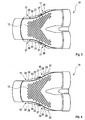
- Fig. 3
- eine Draufsicht auf eine erste Halbschale des Hohlkörpers,
- Fig. 4
- eine Draufsicht auf eine zweite Halbschale des Hohlkörpers,
- Fig. 5
- eine Draufsicht auf die erste Halbschale im Bereich einer Lasche,
- Fig. 6
- eine Seitenansicht auf den Hohlkörper während der Montage, bei verschiedenen Montagezuständen a bis c,
- Fig. 7 und 8
- weitere Seitenansichten auf den Hohlkörper im Bereich einer Lasche bei verschiedenen anderen Ausführungsformen.
- Fig. 1
- a greatly simplified schematic representation of a muffler with a hollow body,
- Fig. 2
- a simplified plan view of a designed as a Y-tube hollow body,
- Fig. 3
- a plan view of a first half-shell of the hollow body,
- Fig. 4
- a plan view of a second half-shell of the hollow body,
- Fig. 5
- a plan view of the first half-shell in the region of a tab,
- Fig. 6
- a side view of the hollow body during assembly, in different mounting states A to C,
- FIGS. 7 and 8
- Further side views of the hollow body in the region of a tab in various other embodiments.
Entsprechend
Der Hohlkörper 4 ist in Halbschalenbauweise gefertigt, so dass er zwei Halbschalen 14, 15 besitzt, die im Bereich einer Trennebene 16 aneinander anliegen und aneinander befestigt sind.The
Entsprechend den
In den
Entsprechend den
Zur Realisierung dieser integrierten Befestigungselemente 17, 18 weist jede Halbschale 14, 15 im Bereich der Trennebene 16 an voneinander entfernten Seiten 19, 20 jeweils einen nach außen abstehenden Kragen 21 bzw. 22 auf, nämlich an der einen oder ersten Halbschale 14 je einen ersten Kragen 21 bzw. je einen zweiten Kragen 22 an der anderen oder zweiten Halbschale 15. An diesen Kragen 21, 22 sind die Befestigungselemente 17, 18 ausgebildet. Die genannten Seiten 19, 20 sind zweckmäßig quer zu einer in
An den zuvor genannten Kragen 21, 22 liegen die beiden Halbschalen 14, 15 aneinander an, was insbesondere den
Anhand der
Entsprechend den
Gemäß
Damit die jeweilige Lasche 26 den zugehörigen Kragenabschnitt 28 übergreifen kann, besitzt der jeweilige Kragen 22 der zweiten Halbschale 15 z. B. zumindest eine Unterbrechung 29, die den jeweiligen Kragen 22 in seiner Kragenlängsrichtung 27 unterbricht und die so bemessen ist, dass die jeweilige Lasche 26 senkrecht zur Trennebene 16 und somit quer zur Längsrichtung 27 des jeweiligen Kragens 21 bzw. 22 durch die jeweilige Unterbrechung 29 hindurchgeführt werden kann. Die Kragen 22 der in
Die
Die Unterbrechungen 29 lassen sich einfach durch Ausstanzen oder Ausschneiden entsprechender Abschnitte des jeweiligen Kragens 22 realisieren. Die Laschen 26 lassen sich dagegen bspw. dadurch realisieren, dass innerhalb des jeweiligen Kragens 21 Längsabschnitte frei geschnitten oder frei gestanzt werden und anschließend ausgestellt werden, so dass die Laschen 26 integrale Bestandteile der Kragen 21 bilden.The
Entsprechend
Um diese sichernde Haltekraft zu erhöhen, kann es gemäß den
Gemäß
Zusätzlich oder alternativ zum jeweiligen Vorsprung 31 und/oder zur jeweiligen Rastkontur 32 kann zumindest eine Einführschräge 35 vorgesehen sein, die in den Beispielen der
Der Montagevorgang, durch den die beiden Halbschalen 14, 15 aneinander befestigt werden, um den Hohlkörper 4 zu bilden, wird nachfolgend anhand der
Entsprechend
Claims (15)
- Silencer for an exhaust system (2) of an internal combustion engine, in particular of a motor vehicle,- comprising a silencer housing (3), which encloses a housing interior (5)- comprising at least one exhaust-gas-carrying hollow body (4) in a half-shell construction, arranged in the housing interior (5),- the two half shells (14, 15) of the hollow body (4) being fastened to each other in the region of a separating plane (16),- the two half shells (14, 15) being fastened to each other by fastening elements (17, 18), which are formed directly on said half shells (14, 15),- the two half shells (14, 15) each comprising in the region of the separating plane (16), on faces (19, 20) which are remote from each other, an outwardly projecting collar (21, 22) on which the fastening elements (17, 18) are formed,- the two half shells (14, 15) being in contact with each other and being fastened to each other at said collars (21, 22),- at least one of the collars (21) having as a fastening element (17) a bracket (26) which is spaced apart from the separating plane (16), which bracket extends in parallel with the separating plane (16) in the longitudinal direction (27) of each collar (21) and overlaps the corresponding collar (22) of the other half shell (15) in a collar portion (28) acting as a complementary fastening element (18),
characterised in that each bracket (26) of the one collar (21), together with the corresponding collar portion (28) of the other collar (22), forms a closure, in which the two half shells (14, 15) carry out two differently oriented movements in order to fasten the two half shells (14, 15) to each other or to detach the two half shells (14, 15) from each other. - Silencer according to claim 1, characterised in that the two half-shells (14, 15) are fastened to each other without using separate fastening means.
- Silencer according to either claim1 or claim 2, characterised in that the corresponding collar (22) of the other half shell (15) comprises at least one interruption (29), through which the bracket (26) can be passed during assembly of the hollow body (4), transversely to the longitudinal direction (27) of the collar (22).
- Silencer according to claim 3, characterised in that each interruption (29) is open laterally on an outer side remote from the gas-carrying interior of the hollow body (4).
- Silencer according to any of claims 1 to 4, characterised in that, relative to the longitudinal direction (27) of the respective collar (22), each bracket (26) overlaps a start region (30) or an end region of the corresponding collar (22) of the other half shell (15).
- Silencer according to any of claims 1 to 5, characterised in that each bracket (26) overlaps the corresponding longitudinal portion (28) in the longitudinal direction (27).
- Silencer according to any of claims 1 to 6, characterised in that each bracket (26) overlaps the corresponding longitudinal portion (28) only in the longitudinal direction (27).
- Silencer according to any of claims 1 to 7, characterised in that each bracket (26) is fixed to the corresponding longitudinal portion (28) with a force fit and/or interlocking fit.
- Silencer according to any of claims 1 to 8, characterised in that the corresponding collar (22) of the other half shell (15) in the collar portion (28) which is overlapped by the bracket (26) comprises a projection (31) which protrudes perpendicularly to the separating plane (16) towards said bracket (26).
- Silencer according to claim 9, characterised in that- the projection (31) is formed by an embossing process on each collar (22), and/or- each bracket (26) comprises a locking contour (32) which is locked with the respective projection (31).
- Silencer according to any of claims 1 to 10, characterised in that each bracket (26) flares out from the respective collar (21).
- Silencer according to any of claims 1 to 11, characterised in that a plurality of brackets (26) are arranged on the same collar (21) so as to be spaced apart from one another in the longitudinal direction (27) of said collar (21).
- Silencer according to any of claims 1 to 12, characterised in that each collar (21) of the one half shell (14) comprises at least one bracket (26).
- Silencer according to any of claims 1 to 13, characterised in that each collar (21) of the one half shell (14) comprises at least two brackets (26), whereas the collar (22) of the other half shell (15) comprises in each case at least one interruption (29).
- Silencer according to any of claims 1 to 14, characterised in that- the hollow body (4) comprises at least one exhaust gas inlet (24) and at least one exhaust gas outlet (25), which in each case are divided, preferably equally, by the separating plane (16), and/or- the two half-shells (14, 15) directly define the respective exhaust gas inlet (24) and the respective exhaust gas outlet (25), and/or- each hollow body (4) is a straight pipe or a curved pipe or a Y-pipe or an X-pipe.
Applications Claiming Priority (2)
| Application Number | Priority Date | Filing Date | Title |
|---|---|---|---|
| DE102010062049A DE102010062049A1 (en) | 2010-11-26 | 2010-11-26 | silencer |
| PCT/EP2011/069229 WO2012069292A1 (en) | 2010-11-26 | 2011-11-02 | Silencer |
Publications (2)
| Publication Number | Publication Date |
|---|---|
| EP2643569A1 EP2643569A1 (en) | 2013-10-02 |
| EP2643569B1 true EP2643569B1 (en) | 2015-07-08 |
Family
ID=44903245
Family Applications (1)
| Application Number | Title | Priority Date | Filing Date |
|---|---|---|---|
| EP11776805.1A Active EP2643569B1 (en) | 2010-11-26 | 2011-11-02 | Silencer |
Country Status (10)
| Country | Link |
|---|---|
| US (1) | US8307944B2 (en) |
| EP (1) | EP2643569B1 (en) |
| JP (1) | JP5657132B2 (en) |
| KR (1) | KR101639111B1 (en) |
| CN (1) | CN103249925B (en) |
| CA (1) | CA2817806C (en) |
| DE (1) | DE102010062049A1 (en) |
| RU (1) | RU2565628C2 (en) |
| WO (1) | WO2012069292A1 (en) |
| ZA (1) | ZA201302406B (en) |
Families Citing this family (4)
| Publication number | Priority date | Publication date | Assignee | Title |
|---|---|---|---|---|
| DE102013204732A1 (en) * | 2013-03-18 | 2014-09-18 | Eberspächer Exhaust Technology GmbH & Co. KG | insulation |
| US20160040942A1 (en) | 2014-08-08 | 2016-02-11 | Halla Visteon Climate Control Corp. | Heat exchanger with integrated noise suppression |
| DE102015223680A1 (en) * | 2015-11-30 | 2017-06-01 | Eberspächer Exhaust Technology GmbH & Co. KG | silencer |
| DE102020109817A1 (en) * | 2020-04-08 | 2021-10-14 | Purem GmbH | Insert assembly for a muffler of an exhaust system of an internal combustion engine |
Family Cites Families (37)
| Publication number | Priority date | Publication date | Assignee | Title |
|---|---|---|---|---|
| US3381774A (en) * | 1967-07-10 | 1968-05-07 | Mercury Metal Products Inc | Muffler with interconnected end bells and telescoped inner pipe |
| DE2243251B2 (en) * | 1972-09-02 | 1976-01-02 | Paul Gillet Gmbh, 6732 Edenkoben | Device for cleaning exhaust gases from internal combustion engines |
| JPS5087315U (en) * | 1973-12-15 | 1975-07-24 | ||
| US4032310A (en) * | 1974-05-15 | 1977-06-28 | Ignoffo Vincent E | Muffler and exhaust gas purifier for internal combustion engines |
| FR2345586A1 (en) * | 1976-03-24 | 1977-10-21 | Nihon Radiator Co | EXHAUST |
| CH632318A5 (en) * | 1978-03-08 | 1982-09-30 | Josef Meier | MUFFLER FOR THE EXHAUST PIPE OF AN INTERNAL COMBUSTION ENGINE, ESPECIALLY A PLANE ENGINE. |
| US4283368A (en) * | 1978-06-27 | 1981-08-11 | Toyo Kogyo Co., Ltd. | Radial flow catalytic converter |
| JPS5698521A (en) * | 1980-12-02 | 1981-08-08 | Nippon Radiator Co Ltd | Method of manufacturing exhaust pipe for silencer |
| JPS59174310U (en) * | 1983-05-10 | 1984-11-21 | マツダ株式会社 | engine exhaust system |
| US4570747A (en) * | 1984-09-18 | 1986-02-18 | Maremont Corporation | Mechanical lock joint for joining tubular products |
| DE3826707A1 (en) * | 1988-08-05 | 1990-02-08 | Gruenzweig & Hartmann | METHOD FOR PRODUCING AN EXHAUST MUFFLER |
| JP2603033B2 (en) * | 1991-08-30 | 1997-04-23 | ブリッグス アンド ストラットン コーポレイション | Exhaust muffler |
| US5290974A (en) * | 1993-03-12 | 1994-03-01 | Arvin Industries, Inc. | Tab and notch locator for exhaust systems |
| US5548955A (en) * | 1994-10-19 | 1996-08-27 | Briggs & Stratton Corporation | Catalytic converter having a venturi formed from two stamped components |
| US5746986A (en) * | 1994-12-30 | 1998-05-05 | Waukesha-Pearce Industries, Inc. | Industrial catalytic converter and combination industrial catalytic converter and silencer |
| DE19611133A1 (en) * | 1996-03-21 | 1997-09-25 | Eberspaecher J | Muffler arrangement |
| US5959263A (en) * | 1998-05-07 | 1999-09-28 | Biggs Manufacturing, Inc. | Bypass muffler |
| DE19834822A1 (en) * | 1998-08-01 | 2000-02-03 | Stihl Maschf Andreas | Exhaust silencer with a catalytic converter |
| US6250422B1 (en) * | 1998-12-14 | 2001-06-26 | Nelson Industries, Inc. | Dual cross-flow muffler |
| GB2346413B (en) * | 1999-02-05 | 2003-08-13 | Komatsu Mfg Co Ltd | Exhaust silencer |
| DE60122688T2 (en) * | 2000-03-21 | 2008-02-07 | Silentor Holding A/S | MUFFLER WITH ONE OR MORE POROUS BODIES |
| DE10060522B4 (en) * | 2000-12-06 | 2004-07-22 | J. Eberspächer GmbH & Co. KG | Exhaust silencer for a fuel-operated heater |
| JP2002276356A (en) * | 2001-03-19 | 2002-09-25 | Mazda Motor Corp | Exhaust structure for on-vehicle engine |
| US6789644B2 (en) * | 2001-11-06 | 2004-09-14 | Hiraoka Manufacturing Co., Ltd. | Engine muffler |
| JP4474111B2 (en) * | 2003-03-31 | 2010-06-02 | 本田技研工業株式会社 | Motorcycle |
| DE10339811B4 (en) * | 2003-08-27 | 2005-09-22 | J. Eberspächer GmbH & Co. KG | Resonator for reducing airborne sound |
| DE10346552A1 (en) * | 2003-10-07 | 2005-06-30 | Friedrich Boysen Gmbh & Co. Kg | Luftspaltkrümmer |
| JP4375061B2 (en) * | 2004-03-03 | 2009-12-02 | 日産自動車株式会社 | Heat insulation structure of exhaust manifold and catalyst |
| JP4381868B2 (en) * | 2004-04-07 | 2009-12-09 | 本田技研工業株式会社 | Exhaust muffler with engine exhaust purification function |
| JP2006070705A (en) * | 2004-08-31 | 2006-03-16 | Honda Motor Co Ltd | Exhaust system of vehicular engine |
| MY148994A (en) * | 2005-06-23 | 2013-06-28 | Honda Motor Co Ltd | Muffler unit for general-purpose engine |
| JP2008111357A (en) * | 2006-10-30 | 2008-05-15 | Yamaha Motor Co Ltd | Gas exhaust system of motorcycle |
| JP2009052539A (en) * | 2007-08-01 | 2009-03-12 | Futaba Industrial Co Ltd | Exhaust pipe connection structure and exhaust pipe connection method |
| DE102008018085A1 (en) * | 2008-04-09 | 2009-10-15 | J. Eberspächer GmbH & Co. KG | Active muffler |
| DE102008061829A1 (en) * | 2008-12-11 | 2010-07-08 | J. Eberspächer GmbH & Co. KG | X-pipe and associated exhaust system |
| RU84205U8 (en) * | 2009-03-10 | 2009-10-20 | ООО "Рубин" | ROAD DEVICE FOR HEAT PROCESSING OF FOOD PRODUCTS (OPTIONS) |
| US8083026B1 (en) * | 2010-06-07 | 2011-12-27 | Butler Boyd L | Diffuser muffler |
-
2010
- 2010-11-26 DE DE102010062049A patent/DE102010062049A1/en not_active Withdrawn
-
2011
- 2011-09-23 US US13/242,142 patent/US8307944B2/en active Active
- 2011-11-02 CA CA2817806A patent/CA2817806C/en active Active
- 2011-11-02 RU RU2013116352/06A patent/RU2565628C2/en active
- 2011-11-02 JP JP2013540294A patent/JP5657132B2/en active Active
- 2011-11-02 KR KR1020137014133A patent/KR101639111B1/en active IP Right Grant
- 2011-11-02 WO PCT/EP2011/069229 patent/WO2012069292A1/en active Application Filing
- 2011-11-02 CN CN201180056381.XA patent/CN103249925B/en active Active
- 2011-11-02 EP EP11776805.1A patent/EP2643569B1/en active Active
-
2013
- 2013-04-04 ZA ZA2013/02406A patent/ZA201302406B/en unknown
Also Published As
| Publication number | Publication date |
|---|---|
| DE102010062049A1 (en) | 2012-05-31 |
| EP2643569A1 (en) | 2013-10-02 |
| KR20140037015A (en) | 2014-03-26 |
| ZA201302406B (en) | 2013-11-27 |
| CN103249925B (en) | 2015-08-19 |
| US8307944B2 (en) | 2012-11-13 |
| CA2817806C (en) | 2017-01-17 |
| RU2565628C2 (en) | 2015-10-20 |
| CA2817806A1 (en) | 2012-05-31 |
| RU2013116352A (en) | 2015-01-10 |
| KR101639111B1 (en) | 2016-07-12 |
| JP5657132B2 (en) | 2015-01-21 |
| JP2013543949A (en) | 2013-12-09 |
| US20120132478A1 (en) | 2012-05-31 |
| CN103249925A (en) | 2013-08-14 |
| WO2012069292A1 (en) | 2012-05-31 |
Similar Documents
| Publication | Publication Date | Title |
|---|---|---|
| EP2385225B1 (en) | Silencer | |
| EP2233709B1 (en) | Exhaust treatment device | |
| EP2980379B2 (en) | Injection device and method of manufacturing the same | |
| DE102011077183B4 (en) | Silencer and manufacturing process | |
| EP2354483B1 (en) | Exhaust muffler | |
| DE102011077645A1 (en) | Static mixer | |
| DE102014215083A1 (en) | Mixer and mixing device for an exhaust system | |
| EP3303816B1 (en) | Vehicle silencer | |
| WO2012172017A1 (en) | Filter element | |
| EP3015672A1 (en) | Exhaust gas treatment device | |
| EP2643569B1 (en) | Silencer | |
| EP3140525A1 (en) | Tailpipe cover for an exhaust system of a motor vehicle and exhaust system having such a tailpipe cover | |
| EP3098405A1 (en) | Exhaust gas treatment device with exchangeable insert | |
| EP3549663B1 (en) | Waste gas system and mixing assembly for a waste gas system | |
| EP2639423B1 (en) | Exhaust gas silencer | |
| DE102017005356A1 (en) | Exhaust after-treatment device of an internal combustion engine of a motor vehicle | |
| EP3173595B1 (en) | Silencer | |
| EP3245396B1 (en) | Muffler for a vehicle | |
| WO2012035163A1 (en) | Exhaust gas treatment unit for an exhaust gas recirculation line | |
| EP1726794A1 (en) | Exhaust gas silencer and method of manufacturing | |
| EP4108890B1 (en) | Method of manufacturing a silencer and corrresponding silencer | |
| EP4098851B1 (en) | Silencer | |
| DE9417244U1 (en) | Silencers, in particular resonator silencers, catalytic converters or the like. |
Legal Events
| Date | Code | Title | Description |
|---|---|---|---|
| PUAI | Public reference made under article 153(3) epc to a published international application that has entered the european phase |
Free format text: ORIGINAL CODE: 0009012 |
|
| 17P | Request for examination filed |
Effective date: 20130514 |
|
| AK | Designated contracting states |
Kind code of ref document: A1 Designated state(s): AL AT BE BG CH CY CZ DE DK EE ES FI FR GB GR HR HU IE IS IT LI LT LU LV MC MK MT NL NO PL PT RO RS SE SI SK SM TR |
|
| DAX | Request for extension of the european patent (deleted) | ||
| GRAP | Despatch of communication of intention to grant a patent |
Free format text: ORIGINAL CODE: EPIDOSNIGR1 |
|
| INTG | Intention to grant announced |
Effective date: 20150317 |
|
| GRAS | Grant fee paid |
Free format text: ORIGINAL CODE: EPIDOSNIGR3 |
|
| GRAA | (expected) grant |
Free format text: ORIGINAL CODE: 0009210 |
|
| AK | Designated contracting states |
Kind code of ref document: B1 Designated state(s): AL AT BE BG CH CY CZ DE DK EE ES FI FR GB GR HR HU IE IS IT LI LT LU LV MC MK MT NL NO PL PT RO RS SE SI SK SM TR |
|
| REG | Reference to a national code |
Ref country code: GB Ref legal event code: FG4D Free format text: NOT ENGLISH |
|
| REG | Reference to a national code |
Ref country code: AT Ref legal event code: REF Ref document number: 735603 Country of ref document: AT Kind code of ref document: T Effective date: 20150715 Ref country code: CH Ref legal event code: EP |
|
| REG | Reference to a national code |
Ref country code: IE Ref legal event code: FG4D Free format text: LANGUAGE OF EP DOCUMENT: GERMAN |
|
| REG | Reference to a national code |
Ref country code: DE Ref legal event code: R096 Ref document number: 502011007294 Country of ref document: DE |
|
| REG | Reference to a national code |
Ref country code: SE Ref legal event code: TRGR |
|
| REG | Reference to a national code |
Ref country code: FR Ref legal event code: PLFP Year of fee payment: 5 |
|
| REG | Reference to a national code |
Ref country code: NL Ref legal event code: MP Effective date: 20150708 |
|
| REG | Reference to a national code |
Ref country code: LT Ref legal event code: MG4D |
|
| PG25 | Lapsed in a contracting state [announced via postgrant information from national office to epo] |
Ref country code: GR Free format text: LAPSE BECAUSE OF FAILURE TO SUBMIT A TRANSLATION OF THE DESCRIPTION OR TO PAY THE FEE WITHIN THE PRESCRIBED TIME-LIMIT Effective date: 20151009 Ref country code: FI Free format text: LAPSE BECAUSE OF FAILURE TO SUBMIT A TRANSLATION OF THE DESCRIPTION OR TO PAY THE FEE WITHIN THE PRESCRIBED TIME-LIMIT Effective date: 20150708 Ref country code: NO Free format text: LAPSE BECAUSE OF FAILURE TO SUBMIT A TRANSLATION OF THE DESCRIPTION OR TO PAY THE FEE WITHIN THE PRESCRIBED TIME-LIMIT Effective date: 20151008 Ref country code: LV Free format text: LAPSE BECAUSE OF FAILURE TO SUBMIT A TRANSLATION OF THE DESCRIPTION OR TO PAY THE FEE WITHIN THE PRESCRIBED TIME-LIMIT Effective date: 20150708 Ref country code: LT Free format text: LAPSE BECAUSE OF FAILURE TO SUBMIT A TRANSLATION OF THE DESCRIPTION OR TO PAY THE FEE WITHIN THE PRESCRIBED TIME-LIMIT Effective date: 20150708 |
|
| PG25 | Lapsed in a contracting state [announced via postgrant information from national office to epo] |
Ref country code: PL Free format text: LAPSE BECAUSE OF FAILURE TO SUBMIT A TRANSLATION OF THE DESCRIPTION OR TO PAY THE FEE WITHIN THE PRESCRIBED TIME-LIMIT Effective date: 20150708 Ref country code: HR Free format text: LAPSE BECAUSE OF FAILURE TO SUBMIT A TRANSLATION OF THE DESCRIPTION OR TO PAY THE FEE WITHIN THE PRESCRIBED TIME-LIMIT Effective date: 20150708 Ref country code: RS Free format text: LAPSE BECAUSE OF FAILURE TO SUBMIT A TRANSLATION OF THE DESCRIPTION OR TO PAY THE FEE WITHIN THE PRESCRIBED TIME-LIMIT Effective date: 20150708 Ref country code: ES Free format text: LAPSE BECAUSE OF FAILURE TO SUBMIT A TRANSLATION OF THE DESCRIPTION OR TO PAY THE FEE WITHIN THE PRESCRIBED TIME-LIMIT Effective date: 20150708 Ref country code: IS Free format text: LAPSE BECAUSE OF FAILURE TO SUBMIT A TRANSLATION OF THE DESCRIPTION OR TO PAY THE FEE WITHIN THE PRESCRIBED TIME-LIMIT Effective date: 20151108 Ref country code: PT Free format text: LAPSE BECAUSE OF FAILURE TO SUBMIT A TRANSLATION OF THE DESCRIPTION OR TO PAY THE FEE WITHIN THE PRESCRIBED TIME-LIMIT Effective date: 20151109 |
|
| REG | Reference to a national code |
Ref country code: DE Ref legal event code: R097 Ref document number: 502011007294 Country of ref document: DE |
|
| PG25 | Lapsed in a contracting state [announced via postgrant information from national office to epo] |
Ref country code: SK Free format text: LAPSE BECAUSE OF FAILURE TO SUBMIT A TRANSLATION OF THE DESCRIPTION OR TO PAY THE FEE WITHIN THE PRESCRIBED TIME-LIMIT Effective date: 20150708 Ref country code: EE Free format text: LAPSE BECAUSE OF FAILURE TO SUBMIT A TRANSLATION OF THE DESCRIPTION OR TO PAY THE FEE WITHIN THE PRESCRIBED TIME-LIMIT Effective date: 20150708 Ref country code: CZ Free format text: LAPSE BECAUSE OF FAILURE TO SUBMIT A TRANSLATION OF THE DESCRIPTION OR TO PAY THE FEE WITHIN THE PRESCRIBED TIME-LIMIT Effective date: 20150708 Ref country code: DK Free format text: LAPSE BECAUSE OF FAILURE TO SUBMIT A TRANSLATION OF THE DESCRIPTION OR TO PAY THE FEE WITHIN THE PRESCRIBED TIME-LIMIT Effective date: 20150708 |
|
| PLBE | No opposition filed within time limit |
Free format text: ORIGINAL CODE: 0009261 |
|
| STAA | Information on the status of an ep patent application or granted ep patent |
Free format text: STATUS: NO OPPOSITION FILED WITHIN TIME LIMIT |
|
| PG25 | Lapsed in a contracting state [announced via postgrant information from national office to epo] |
Ref country code: RO Free format text: LAPSE BECAUSE OF FAILURE TO SUBMIT A TRANSLATION OF THE DESCRIPTION OR TO PAY THE FEE WITHIN THE PRESCRIBED TIME-LIMIT Effective date: 20150708 |
|
| 26N | No opposition filed |
Effective date: 20160411 |
|
| PG25 | Lapsed in a contracting state [announced via postgrant information from national office to epo] |
Ref country code: LU Free format text: LAPSE BECAUSE OF FAILURE TO SUBMIT A TRANSLATION OF THE DESCRIPTION OR TO PAY THE FEE WITHIN THE PRESCRIBED TIME-LIMIT Effective date: 20151102 Ref country code: MC Free format text: LAPSE BECAUSE OF FAILURE TO SUBMIT A TRANSLATION OF THE DESCRIPTION OR TO PAY THE FEE WITHIN THE PRESCRIBED TIME-LIMIT Effective date: 20150708 |
|
| REG | Reference to a national code |
Ref country code: CH Ref legal event code: PL |
|
| PG25 | Lapsed in a contracting state [announced via postgrant information from national office to epo] |
Ref country code: CH Free format text: LAPSE BECAUSE OF NON-PAYMENT OF DUE FEES Effective date: 20151130 Ref country code: LI Free format text: LAPSE BECAUSE OF NON-PAYMENT OF DUE FEES Effective date: 20151130 |
|
| REG | Reference to a national code |
Ref country code: IE Ref legal event code: MM4A |
|
| PG25 | Lapsed in a contracting state [announced via postgrant information from national office to epo] |
Ref country code: SI Free format text: LAPSE BECAUSE OF FAILURE TO SUBMIT A TRANSLATION OF THE DESCRIPTION OR TO PAY THE FEE WITHIN THE PRESCRIBED TIME-LIMIT Effective date: 20150708 |
|
| PG25 | Lapsed in a contracting state [announced via postgrant information from national office to epo] |
Ref country code: IE Free format text: LAPSE BECAUSE OF NON-PAYMENT OF DUE FEES Effective date: 20151102 |
|
| REG | Reference to a national code |
Ref country code: FR Ref legal event code: PLFP Year of fee payment: 6 |
|
| PG25 | Lapsed in a contracting state [announced via postgrant information from national office to epo] |
Ref country code: BG Free format text: LAPSE BECAUSE OF FAILURE TO SUBMIT A TRANSLATION OF THE DESCRIPTION OR TO PAY THE FEE WITHIN THE PRESCRIBED TIME-LIMIT Effective date: 20150708 Ref country code: SM Free format text: LAPSE BECAUSE OF FAILURE TO SUBMIT A TRANSLATION OF THE DESCRIPTION OR TO PAY THE FEE WITHIN THE PRESCRIBED TIME-LIMIT Effective date: 20150708 Ref country code: HU Free format text: LAPSE BECAUSE OF FAILURE TO SUBMIT A TRANSLATION OF THE DESCRIPTION OR TO PAY THE FEE WITHIN THE PRESCRIBED TIME-LIMIT; INVALID AB INITIO Effective date: 20111102 |
|
| PG25 | Lapsed in a contracting state [announced via postgrant information from national office to epo] |
Ref country code: NL Free format text: LAPSE BECAUSE OF FAILURE TO SUBMIT A TRANSLATION OF THE DESCRIPTION OR TO PAY THE FEE WITHIN THE PRESCRIBED TIME-LIMIT Effective date: 20150708 Ref country code: CY Free format text: LAPSE BECAUSE OF FAILURE TO SUBMIT A TRANSLATION OF THE DESCRIPTION OR TO PAY THE FEE WITHIN THE PRESCRIBED TIME-LIMIT Effective date: 20150708 |
|
| PG25 | Lapsed in a contracting state [announced via postgrant information from national office to epo] |
Ref country code: BE Free format text: LAPSE BECAUSE OF NON-PAYMENT OF DUE FEES Effective date: 20151130 |
|
| PG25 | Lapsed in a contracting state [announced via postgrant information from national office to epo] |
Ref country code: MT Free format text: LAPSE BECAUSE OF FAILURE TO SUBMIT A TRANSLATION OF THE DESCRIPTION OR TO PAY THE FEE WITHIN THE PRESCRIBED TIME-LIMIT Effective date: 20150708 |
|
| REG | Reference to a national code |
Ref country code: FR Ref legal event code: PLFP Year of fee payment: 7 |
|
| REG | Reference to a national code |
Ref country code: AT Ref legal event code: MM01 Ref document number: 735603 Country of ref document: AT Kind code of ref document: T Effective date: 20161102 |
|
| PG25 | Lapsed in a contracting state [announced via postgrant information from national office to epo] |
Ref country code: AT Free format text: LAPSE BECAUSE OF NON-PAYMENT OF DUE FEES Effective date: 20161102 |
|
| PGFP | Annual fee paid to national office [announced via postgrant information from national office to epo] |
Ref country code: IT Payment date: 20171122 Year of fee payment: 7 |
|
| PG25 | Lapsed in a contracting state [announced via postgrant information from national office to epo] |
Ref country code: MK Free format text: LAPSE BECAUSE OF FAILURE TO SUBMIT A TRANSLATION OF THE DESCRIPTION OR TO PAY THE FEE WITHIN THE PRESCRIBED TIME-LIMIT Effective date: 20150708 |
|
| PG25 | Lapsed in a contracting state [announced via postgrant information from national office to epo] |
Ref country code: AL Free format text: LAPSE BECAUSE OF FAILURE TO SUBMIT A TRANSLATION OF THE DESCRIPTION OR TO PAY THE FEE WITHIN THE PRESCRIBED TIME-LIMIT Effective date: 20150708 |
|
| PG25 | Lapsed in a contracting state [announced via postgrant information from national office to epo] |
Ref country code: IT Free format text: LAPSE BECAUSE OF NON-PAYMENT OF DUE FEES Effective date: 20181102 |
|
| REG | Reference to a national code |
Ref country code: DE Ref legal event code: R081 Ref document number: 502011007294 Country of ref document: DE Owner name: PUREM GMBH, DE Free format text: FORMER OWNER: EBERSPAECHER EXHAUST TECHNOLOGY GMBH & CO. KG, 66539 NEUNKIRCHEN, DE |
|
| PGFP | Annual fee paid to national office [announced via postgrant information from national office to epo] |
Ref country code: SE Payment date: 20211123 Year of fee payment: 11 |
|
| PGFP | Annual fee paid to national office [announced via postgrant information from national office to epo] |
Ref country code: TR Payment date: 20221026 Year of fee payment: 12 |
|
| REG | Reference to a national code |
Ref country code: SE Ref legal event code: EUG |
|
| PG25 | Lapsed in a contracting state [announced via postgrant information from national office to epo] |
Ref country code: SE Free format text: LAPSE BECAUSE OF NON-PAYMENT OF DUE FEES Effective date: 20221103 |
|
| PGFP | Annual fee paid to national office [announced via postgrant information from national office to epo] |
Ref country code: GB Payment date: 20231123 Year of fee payment: 13 |
|
| PGFP | Annual fee paid to national office [announced via postgrant information from national office to epo] |
Ref country code: FR Payment date: 20231123 Year of fee payment: 13 Ref country code: DE Payment date: 20231120 Year of fee payment: 13 |