EP2643569B1 - Silencieux - Google Patents
Silencieux Download PDFInfo
- Publication number
- EP2643569B1 EP2643569B1 EP11776805.1A EP11776805A EP2643569B1 EP 2643569 B1 EP2643569 B1 EP 2643569B1 EP 11776805 A EP11776805 A EP 11776805A EP 2643569 B1 EP2643569 B1 EP 2643569B1
- Authority
- EP
- European Patent Office
- Prior art keywords
- collar
- bracket
- shells
- silencer according
- hollow body
- Prior art date
- Legal status (The legal status is an assumption and is not a legal conclusion. Google has not performed a legal analysis and makes no representation as to the accuracy of the status listed.)
- Active
Links
- 230000003584 silencer Effects 0.000 title claims description 19
- 238000010276 construction Methods 0.000 claims description 7
- 238000000034 method Methods 0.000 claims description 6
- 230000000295 complement effect Effects 0.000 claims description 5
- 238000002485 combustion reaction Methods 0.000 claims description 4
- 238000004049 embossing Methods 0.000 claims description 3
- 239000007789 gas Substances 0.000 description 19
- 238000004519 manufacturing process Methods 0.000 description 4
- 238000005520 cutting process Methods 0.000 description 3
- 238000003780 insertion Methods 0.000 description 3
- 230000037431 insertion Effects 0.000 description 3
- 238000004080 punching Methods 0.000 description 3
- 238000010521 absorption reaction Methods 0.000 description 2
- 230000001419 dependent effect Effects 0.000 description 2
- 230000000694 effects Effects 0.000 description 2
- 230000001747 exhibiting effect Effects 0.000 description 2
- 239000002184 metal Substances 0.000 description 2
- 230000008878 coupling Effects 0.000 description 1
- 238000010168 coupling process Methods 0.000 description 1
- 238000005859 coupling reaction Methods 0.000 description 1
- 238000013016 damping Methods 0.000 description 1
- 238000007599 discharging Methods 0.000 description 1
- 238000002955 isolation Methods 0.000 description 1
- 230000003068 static effect Effects 0.000 description 1
- 238000004804 winding Methods 0.000 description 1
Images


Classifications
-
- F—MECHANICAL ENGINEERING; LIGHTING; HEATING; WEAPONS; BLASTING
- F16—ENGINEERING ELEMENTS AND UNITS; GENERAL MEASURES FOR PRODUCING AND MAINTAINING EFFECTIVE FUNCTIONING OF MACHINES OR INSTALLATIONS; THERMAL INSULATION IN GENERAL
- F16B—DEVICES FOR FASTENING OR SECURING CONSTRUCTIONAL ELEMENTS OR MACHINE PARTS TOGETHER, e.g. NAILS, BOLTS, CIRCLIPS, CLAMPS, CLIPS OR WEDGES; JOINTS OR JOINTING
- F16B5/00—Joining sheets or plates, e.g. panels, to one another or to strips or bars parallel to them
- F16B5/07—Joining sheets or plates, e.g. panels, to one another or to strips or bars parallel to them by means of multiple interengaging protrusions on the surfaces, e.g. hooks, coils
-
- F—MECHANICAL ENGINEERING; LIGHTING; HEATING; WEAPONS; BLASTING
- F01—MACHINES OR ENGINES IN GENERAL; ENGINE PLANTS IN GENERAL; STEAM ENGINES
- F01N—GAS-FLOW SILENCERS OR EXHAUST APPARATUS FOR MACHINES OR ENGINES IN GENERAL; GAS-FLOW SILENCERS OR EXHAUST APPARATUS FOR INTERNAL COMBUSTION ENGINES
- F01N13/00—Exhaust or silencing apparatus characterised by constructional features ; Exhaust or silencing apparatus, or parts thereof, having pertinent characteristics not provided for in, or of interest apart from, groups F01N1/00 - F01N5/00, F01N9/00, F01N11/00
- F01N13/18—Construction facilitating manufacture, assembly, or disassembly
- F01N13/1838—Construction facilitating manufacture, assembly, or disassembly characterised by the type of connection between parts of exhaust or silencing apparatus, e.g. between housing and tubes, between tubes and baffles
-
- F—MECHANICAL ENGINEERING; LIGHTING; HEATING; WEAPONS; BLASTING
- F01—MACHINES OR ENGINES IN GENERAL; ENGINE PLANTS IN GENERAL; STEAM ENGINES
- F01N—GAS-FLOW SILENCERS OR EXHAUST APPARATUS FOR MACHINES OR ENGINES IN GENERAL; GAS-FLOW SILENCERS OR EXHAUST APPARATUS FOR INTERNAL COMBUSTION ENGINES
- F01N1/00—Silencing apparatus characterised by method of silencing
- F01N1/06—Silencing apparatus characterised by method of silencing by using interference effect
-
- F—MECHANICAL ENGINEERING; LIGHTING; HEATING; WEAPONS; BLASTING
- F01—MACHINES OR ENGINES IN GENERAL; ENGINE PLANTS IN GENERAL; STEAM ENGINES
- F01N—GAS-FLOW SILENCERS OR EXHAUST APPARATUS FOR MACHINES OR ENGINES IN GENERAL; GAS-FLOW SILENCERS OR EXHAUST APPARATUS FOR INTERNAL COMBUSTION ENGINES
- F01N13/00—Exhaust or silencing apparatus characterised by constructional features ; Exhaust or silencing apparatus, or parts thereof, having pertinent characteristics not provided for in, or of interest apart from, groups F01N1/00 - F01N5/00, F01N9/00, F01N11/00
- F01N13/18—Construction facilitating manufacture, assembly, or disassembly
- F01N13/1872—Construction facilitating manufacture, assembly, or disassembly the assembly using stamp-formed parts or otherwise deformed sheet-metal
-
- F—MECHANICAL ENGINEERING; LIGHTING; HEATING; WEAPONS; BLASTING
- F01—MACHINES OR ENGINES IN GENERAL; ENGINE PLANTS IN GENERAL; STEAM ENGINES
- F01N—GAS-FLOW SILENCERS OR EXHAUST APPARATUS FOR MACHINES OR ENGINES IN GENERAL; GAS-FLOW SILENCERS OR EXHAUST APPARATUS FOR INTERNAL COMBUSTION ENGINES
- F01N2450/00—Methods or apparatus for fitting, inserting or repairing different elements
- F01N2450/18—Methods or apparatus for fitting, inserting or repairing different elements by using quick-active type locking mechanisms, e.g. clips
-
- F—MECHANICAL ENGINEERING; LIGHTING; HEATING; WEAPONS; BLASTING
- F01—MACHINES OR ENGINES IN GENERAL; ENGINE PLANTS IN GENERAL; STEAM ENGINES
- F01N—GAS-FLOW SILENCERS OR EXHAUST APPARATUS FOR MACHINES OR ENGINES IN GENERAL; GAS-FLOW SILENCERS OR EXHAUST APPARATUS FOR INTERNAL COMBUSTION ENGINES
- F01N2450/00—Methods or apparatus for fitting, inserting or repairing different elements
- F01N2450/20—Methods or apparatus for fitting, inserting or repairing different elements by mechanical joints, e.g. by deforming housing, tube, baffle plate or parts thereof
-
- F—MECHANICAL ENGINEERING; LIGHTING; HEATING; WEAPONS; BLASTING
- F01—MACHINES OR ENGINES IN GENERAL; ENGINE PLANTS IN GENERAL; STEAM ENGINES
- F01N—GAS-FLOW SILENCERS OR EXHAUST APPARATUS FOR MACHINES OR ENGINES IN GENERAL; GAS-FLOW SILENCERS OR EXHAUST APPARATUS FOR INTERNAL COMBUSTION ENGINES
- F01N2450/00—Methods or apparatus for fitting, inserting or repairing different elements
- F01N2450/26—Methods or apparatus for fitting, inserting or repairing different elements by bayonet fittings
-
- F—MECHANICAL ENGINEERING; LIGHTING; HEATING; WEAPONS; BLASTING
- F01—MACHINES OR ENGINES IN GENERAL; ENGINE PLANTS IN GENERAL; STEAM ENGINES
- F01N—GAS-FLOW SILENCERS OR EXHAUST APPARATUS FOR MACHINES OR ENGINES IN GENERAL; GAS-FLOW SILENCERS OR EXHAUST APPARATUS FOR INTERNAL COMBUSTION ENGINES
- F01N2470/00—Structure or shape of gas passages, pipes or tubes
- F01N2470/06—Tubes being formed by assembly of stamped or otherwise deformed sheet-metal
Definitions
- the present invention relates to a silencer for an exhaust system of an internal combustion engine, in particular of a motor vehicle, having the features of the preamble of claim 1.
- a muffler comprises a muffler housing, which encloses a housing interior, wherein in the housing interior at least one exhaust-carrying hollow body is arranged, for example.
- a tube in particular in the form of a deflection tube or in the form of an X or Y tube.
- a muffler for an exhaust system of an internal combustion engine in which a muffler housing encloses a housing interior in which an exhaust-carrying hollow body is arranged in a half-shell construction.
- the two half-shells of the hollow body are fastened together in the region of a parting plane by fastening elements, which are formed directly on the half-shells.
- one of the collars has a tab spaced apart from the parting plane as a fastening element, which extends parallel to the Dividing plane extends in the longitudinal direction of the respective collar and engages over the associated collar of the other half-shell in a serving as a complementary fastener collar portion.
- the respective collar of one half-shell engages around the associated complementary collar portion of the other half-shell in the manner of a crimp connection.
- the present invention is concerned with the problem of providing for such a silencer an improved embodiment, which is characterized in particular by a particularly inexpensive manufacturability.
- the invention is based on the general idea of mechanically fixing the two half-shells directly to one another in the case of a half-shell hollow body without the need for additional fastening means.
- the invention proposes, on the half-shells fastening regions or fastening elements, which cooperate with each other for the mechanical connection of the two half-shells, directly, ie integrally formed on the half-shells.
- These attachment areas or fastening elements can cooperate in the manner of a plug connection or clip connection or latching connection or by a combination of the above connection techniques in order to fix the two half-shells together.
- the two half-shells in the region of the parting plane on each side remote from each other have an outwardly projecting collar, wherein the fastening elements are formed on this collar and wherein the two half-shells abut against each other and are secured together.
- the collars define the relative position between the two half-shells and are particularly suitable for the arrangement of the fastening elements, since they are located outside of a cavity enclosed by the hollow body and accordingly do not affect the exhaust gas duct in the hollow body.
- At least one of the collars of the one half shell has a tab spaced apart from the parting plane as a fastening element which extends parallel to the dividing plane in the longitudinal direction of the respective collar and thereby the associated collar of the other half shell in a Complementary fastener serving collar portion overlaps.
- the tab creates with the associated collar portion, which it overlaps, a positive connection, which determines the two half-shells together securely.
- an embodiment can be realized in which the tabs and the associated collar sections cooperate in the manner of a bayonet closure, which is characterized in that two differently oriented movements must be performed in order to secure the two half-shells together or to separate from each other , When attaching the two half-shells must be inserted in a first direction relative to each other to position the tabs of a collar directly to the associated collar portions of the other collar. Subsequently, the two half-shells must be moved in a second direction relative to each other, so that the tabs can overlap the associated collar sections.
- the associated collar of the other half-shell has at least one interruption, through which the tab during assembly of the hollow body perpendicular to the parting plane, that is transversely to the longitudinal direction of the respective collar can be passed.
- An embodiment in which the respective interruption is laterally open at an outer side facing away from the gas-conducting interior of the hollow body is particularly easy to produce. In this case, for example, manufacturing tolerances can be set comparatively roughly.
- the respective tab can engage over a starting region or end region of the associated collar of the other half shell with respect to the longitudinal direction of the respective collar.
- the tab can also provide a relation to the tab having collar shortened collar at the beginning of the end region or sufficient space available through which the respective tab on can be passed to overarching collar portion during the insertion process, to then overlap it during the sliding process.
- the respective tab the associated longitudinal portion in the longitudinal direction overlaps.
- the respective tab overlaps the associated longitudinal section exclusively in the longitudinal direction.
- the respective tab on the associated longitudinal section is fixed only positively and / or positively, so that can be dispensed with additional, separate fastening means.
- the hollow body is easy to assemble and inexpensive to produce.
- the associated collar of the other half-shell may have at least one projection projecting perpendicularly to the parting plane in the direction of the tab in the collar section overlapped by the tab.
- this projection With the help of this projection, a clamping effect can be generated or amplified, which increases the friction between the tab and the overlapped collar portion. In this way, the fixation of the two half-shells can be improved together.
- said projection can be integrally formed on the respective collar by an embossing process, which simplifies the production of the projection or the half-shell.
- the respective tab has a latching contour which engages with the respective projection.
- the respective tab can be issued by the respective collar.
- the respective tab is formed by free cutting or free punching and exhibiting directly or integrally by a portion of the tab, which simplifies the production of the respective half-shell.
- each collar of a half-shell may have at least one tab.
- each collar of the other half-shell has at least one collar section that can be engaged by the respective tab.
- each collar of a half-shell may have at least two tabs, while the collars of the other half-shell each have at least one interruption. While the respective first tab then cooperates with the respective interruption, the respective second tab can then cooperate with a further interruption or else with a starting region or end region of the respective tab.
- the hollow body may comprise at least one exhaust gas inlet and at least one exhaust gas outlet, which are each divided by the parting plane, preferably in half.
- the exhaust gas inlet or the exhaust gas outlet lie in a plane which runs perpendicular to the parting plane.
- An edge section for the exhaust gas inlet or for the exhaust gas outlet is expediently formed on the respective half shell, which surrounds in the circumferential direction 180 ° of the exhaust gas inlet or the exhaust gas outlet.
- a particularly simple construction results when the two half shells directly form or define the respective exhaust gas inlet and the respective exhaust gas outlet, so that it is possible to dispense with further components, such as end plates or end plates, which contain an opening around an inlet or an outlet to build.
- the hollow body may preferably be a straight tube or a bent deflection tube or a Y-tube. While simple tubes have exactly one inlet and one outlet, a Y-tube has either two inlets and one outlet or inlet and two Outlets. In principle, an X-tube can also form such a hollow body, which has two inlets and two outlets.
- At least one of the half-shells can be equipped with a perforation, whereby the respective hollow body can be guided inside the muffler, for example, through an absorption chamber or through a resonance chamber or through an expansion chamber in order to produce a certain sound-damping effect.
- FIG. 1 includes a muffler 1 of an exhaust system 2 shown here only in the region of the muffler 1, which serves for discharging exhaust gases of an internal combustion engine, not shown here, which may be arranged together with the exhaust system 2 in a motor vehicle, a muffler housing 3 and at least one hollow body.
- the muffler housing 3 encloses a housing interior 5, which may be subdivided into a plurality of chambers 6, 7, 8, for example.
- the hollow body 4 is arranged in the housing interior 5 and serves for exhaust gas routing.
- an inlet pipe 9 can be connected to the muffler housing 3, through which exhaust gas according to arrows 10 enters the inlet chamber or deflection chamber serving first chamber 6 of the housing interior 5 and through the hollow body 4 serving as the outlet chamber or deflection third Chamber 8 of the Housing interior 5 passes, from where the exhaust gas is discharged via an outlet pipe 11.
- the hollow body 4 is passed in the example by serving as an absorption chamber second chamber 7 of the housing interior 5, which is separated by intermediate walls 12 of the other two chambers 6, 8.
- the hollow body 4 may be made permeable to airborne sound in the region of the second chamber 7, for example by means of a perforation 13.
- the hollow body 4 is made in a half-shell construction, so that it has two half-shells 14, 15 which abut each other in the region of a parting plane 16 and are fastened to each other.
- the hollow body 4 may be a Y-tube. Likewise, it may alternatively be an X-tube. Alternatively, the hollow body 4 may also be a bent deflecting tube or an unbent or straight tube.
- the half-shells 14, 15 are fastened to one another with the aid of fastening elements 17, 18, wherein these fastening elements 17, 18 are formed directly on the half-shells 14, 15.
- the fastening elements 17, 18 are integrally formed on the respective half-shell 14, 15.
- the two half-shells 14, 15 are fastened to one another exclusively via these fastening elements 17, 18 formed directly thereon.
- the half-shells 14, 15 are, for example, formed sheet metal parts which are each made with the fastening elements 17, 18 of a piece of sheet metal.
- each half-shell 14, 15 in the region of the parting plane 16 at spaced apart sides 19, 20 each have an outwardly projecting collar 21 and 22, namely at the one or first half-shell 14 each have a first collar 21 or depending on a second collar 22 on the other or second half-shell 15.
- the said pages 19, 20 are suitably transversely to a in Fig. 2 indicated by an arrow flow direction 23 of the hollow body 4 away from each other.
- the hollow body 4 thus has at least one exhaust gas inlet 24 and at least one exhaust gas outlet 25.
- both the inlet opening 24 and the two outlet openings 25 are each arranged in planes which are perpendicular to the parting plane 16.
- the dividing plane 16 expediently divides the respective exhaust gas inlet 24 and the respective exhaust gas outlet 25 in half.
- the two half-shells 14, 15 abut each other, which in particular the Fig. 6 to 8 is removable. Further, the fastening of the half-shells 14, 15 to each other via these collar 21, 22, so that the collar 21, 22 are secured together.
- fastening elements 17, 18 are explained in more detail. It is clear that, in principle, other fastening elements 17, 18 can be used, which enable mechanical fixing of the two half-shells 14, 15 to one another and without additional additional fasteners, such as. For example, brackets, screws, welded joints, get along.
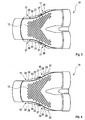
- the two collars 21 of the first half-shell 14 each have at least one tab 26.
- the respective collar 21 has two such tabs 26, so that the first half-shell 14 has four such tabs 26 in the example.
- the respective tab 26 represents the respective fastening element 17 of the first half-shell 14.
- the respective tab 26 extends parallel to the parting plane 16 and spaced therefrom in the longitudinal direction of the respective collar 21 indicated by arrows 27.
- Fig. 4 has the second half-shell 15 at its two collar 22 for each tab 26 of the first half-shell 14 on a collar portion 28 which represents a complementary to the tab 26 and the first fastener 17 second fastener 18.
- the respective tab 26 engages over the associated collar portion 28th
- the respective tab 26 may engage over the associated collar portion 28, the respective collar 22 of the second half-shell 15 has z. B. at least one interruption 29, which interrupts the respective collar 22 in its collar longitudinal direction 27 and which is dimensioned so that the respective tab 26 perpendicular to the parting plane 16 and thus transversely to the longitudinal direction 27 of the respective collar 21 and 22 through the respective interruption 29th can be passed.
- the collar 22 of the Fig. 4 In each case, only one such interruption 29, to each of which one of the collar sections 28 adjoins, is shown.
- the two other collar portions 28, however, are at an initial region 30 of the respective Collar 22 is formed or - depending on the orientation of the longitudinal direction 27 - at an end portion of the respective collar 22.
- the associated tab 26 can also be moved perpendicular to the parting plane 16 on the associated collar portion 28 over.
- Fig. 2 to 4 show embodiments in which a plurality of tabs 26 are arranged on the same collar 21 in the longitudinal direction 27 of the collar 21 spaced from each other.
- each collar 21 exactly two tabs 26 in the collar longitudinal direction 27 are spaced from each other.
- the tabs 26 are formed exclusively on the first half-shell 16, while the tabs 26 associated collar portions 28 are formed here exclusively on the second half-shell 15.
- the interruptions 29 can be realized simply by punching or cutting out corresponding sections of the respective collar 22.
- the tabs 26 can be realized, for example, by freely cutting or longitudinally punching longitudinal sections within the respective collar 21, and then exhibiting them, so that the tabs 26 form integral components of the collars 21.
- Fig. 5 shows the first half-shell 14 in the region of such a cut-free tab 26th
- the respective tab 26 can be spaced from the parting plane 16 so far that the associated collar section 28 is clamped or clamped with a bias oriented perpendicular to the parting plane 16. In conjunction with the static friction can be generated in this way a holding force parallel to the parting plane 16, which secures the half-shells 14, mounted one another in the mounted state.
- FIGS. 7 and 8 be provided to provide the respective collar portion 28 with at least one projection 31 which projects perpendicular to the parting plane 16 in the direction of the tab 26.
- the tab 26 is displaced when passing over the collar portion 28 by the projection 31 in a direction away from the parting plane 16 direction, which increases the bias at which the tab 26 is supported on the collar portion 28 and at the projection 31 perpendicular to the parting plane 16 is.
- a projection 31 may, for example, integrally formed on the respective collar portion 28 by means of an embossing operation.
- the respective tab 26 may be equipped according to a particularly advantageous embodiment with a locking contour 32 which is shaped so that it can lock with the respective projection 31 as soon as the two half shells 14, 15 reach their mounting position.
- the locking contour 32 is from the associated tab 26 in the direction of parting plane 16, whereby the locking contour 32 can engage behind the respective projection 31. This results in a direction parallel to the parting plane 16 a positive connection.
- At least one insertion bevel 35 may be provided, which in the examples of FIGS FIGS. 7 and 8 each formed at the free end of the tab 26 to facilitate the attachment of the respective tab 26 to the associated collar portion 28.
- the two half-shells 14, 15 are initially positioned relative to each other for adjusting a starting position such that the respective tab 26 is aligned perpendicular to the parting plane 16 in alignment with the associated interruption 29. Then, the two half-shells 14, 15 according to arrows 33 perpendicular to the parting plane 16 moves towards each other. In this case, the respective tab 26 can penetrate the associated interruption 29, whereby the in Fig. 6b shown intermediate position is achieved. In this intermediate position, the collars 21, 22 abut each other in the parting plane 16. This first adjustment movement according to the arrows 33 represents a plug-in operation.
Landscapes
- Engineering & Computer Science (AREA)
- General Engineering & Computer Science (AREA)
- Mechanical Engineering (AREA)
- Chemical & Material Sciences (AREA)
- Combustion & Propulsion (AREA)
- Exhaust Silencers (AREA)
- Clamps And Clips (AREA)
Claims (15)
- Silencieux pour une installation de gaz d'échappement (2) d'un moteur à combustion interne, en particulier d'un véhicule automobile,- avec un carter de silencieux (3) qui cerne une chambre intérieure de carter (5),- avec au moins un corps creux (4) de guidage des gaz d'échappement, de structure en demi-coques, disposé dans la chambre intérieure de carter (5),- les deux demi-coques (14, 15) du corps creux (4) étant fixées l'une à l'autre dans la zone d'un plan de séparation (16),- les deux demi-coques (14, 15) étant fixées l'une à l'autre par des éléments de fixation (17, 18) qui sont formés directement au niveau des demi-coques (14, 15),- les deux demi-coques (14, 15) présentant respectivement dans la zone du plan de séparation (16), au niveau de côtés (19, 20) distants l'un de l'autre, un collet (21, 22) saillant vers l'extérieur, au niveau desquels les éléments de fixation (17, 18) sont formés,- les deux demi-coques (14,15) étant juxtaposées l'une à l'autre et fixées l'une à l'autre au niveau de ce collet (21, 22),- tout au moins un des collets (21) présentant, comme élément de fixation (17), une languette (26), distante du plan de séparation (16) et qui s'étend parallèlement au plan de séparation (16) dans le sens longitudinal (27) du collet (21) respectif et qui chevauche de ce fait le collet (22) correspondant de l'autre demi-coque (15) dans une section de collet (28) servant d'élément de fixation (18) complémentaire,
caractérisé en ce que
la languette (26) respective d'un des collets (21) forme avec la section de collet (28) correspondante de l'autre collet (22) une fermeture, dans le cas de laquelle les deux demi-coques (14, 15) exécutent deux mouvements orientés différemment selon qu'il s'agit de fixer les deux demi-coques (14, 15) l'une à l'autre, ou de séparer les deux demi-coques (14, 15) l'une de l'autre. - Silencieux selon la revendication 1,
caractérisé en ce que
les deux demi-coques (14, 15) sont fixées l'une à l'autre sans moyen de fixation séparé. - Silencieux selon la revendication 1 ou 2,
caractérisé en ce que
le collet (22) correspondant de l'autre demi-coque (15) présente tout au moins une interruption (29), à travers laquelle la languette (26) peut passer transversalement au sens longitudinal (27) du collet (22), lors de l'assemblage du corps creux (4). - Silencieux selon la revendication 3,
caractérisé en ce que
l'interruption (29) respective est ouverte latéralement au niveau d'un côté externe opposé à l'intérieur du conduit de guidage des gaz du corps creux (4). - Silencieux selon l'une des revendications 1 à 4,
caractérisé en ce que
la languette (26) respective chevauche, par rapport au sens longitudinal (27) du collet (22) respectif, une zone initiale (30) ou une zone finale du collet (22) correspondant de l'autre demi-coque (15). - Silencieux selon l'une des revendications 1 à 5,
caractérisé en ce que
la languette (26) respective chevauche la section longitudinale (28) correspondante dans le sens longitudinal (27). - Silencieux selon l'une des revendications 1 à 6,
caractérisé en ce que
la languette (26) respective chevauche la section longitudinale (28) correspondante exclusivement dans le sens longitudinal (27). - Silencieux selon l'une des revendications 1 à 7,
caractérisé en ce que
la languette (26) respective est fixée au niveau de la section longitudinale (28) correspondante par coopération de forces et/ou par ajustement de formes. - Silencieux selon l'une des revendications 1 à 8,
caractérisé en ce que
le collet (22) correspondant de l'autre demi-coque (15) présente, dans la section de collet (28) chevauchée par la languette (26), une partie saillante (31) vers l'extérieur dans le sens de la languette (26) et perpendiculaire au plan de séparation (16) - Silencieux selon la revendication 9,
caractérisé en ce que- la partie saillante (31) est formée par un processus de marquage sur le collet (22) respectif et/ou- la languette (26) respective présente un contour d'encliquetage (32) qui est encliqueté avec la partie saillante (31) respective. - Silencieux selon l'une des revendications 1 à 10,
caractérisé en ce que
la languette (26) respective est exposée par le collet (21) respectif. - Silencieux selon l'une des revendications 1 à 11,
caractérisé en ce que
plusieurs languettes (26) sont disposées à distance les unes des autres au niveau du même collet (21), dans le sens longitudinal (27) du collet (21). - Silencieux selon l'une des revendications 1 à 12,
caractérisé en ce que
chaque collet (21) d'une des demi-coques (14) présente au moins une languette (26). - Silencieux selon l'une des revendications 1 à 13,
caractérisé en ce que
chaque collet (21) d'une demi-coque (14) présente au moins deux languettes (26), tandis que les collets (22) de l'autre demi-coque (15) présentent respectivement au moins une interruption (29). - Silencieux selon l'une des revendications 1 à 14,
caractérisé en ce que- le corps creux (4) présente tout au moins une entrée de gaz d'échappement (24) et tout au moins une sortie de gaz d'échappement (25) qui sont respectivement séparées, de préférence pour moitié, du plan de séparation (16) et/ou- les deux demi-coques (14, 15) définissent directement l'entrée de gaz d'échappement (24) respective et la sortie de gaz d'échappement (25) respective, et/ou- le corps creux (4) respectif est un tube rectiligne, ou un tube de déviation coudé, ou un tube en Y ou un tube en X.
Applications Claiming Priority (2)
| Application Number | Priority Date | Filing Date | Title |
|---|---|---|---|
| DE102010062049A DE102010062049A1 (de) | 2010-11-26 | 2010-11-26 | Schalldämpfer |
| PCT/EP2011/069229 WO2012069292A1 (fr) | 2010-11-26 | 2011-11-02 | Silencieux |
Publications (2)
| Publication Number | Publication Date |
|---|---|
| EP2643569A1 EP2643569A1 (fr) | 2013-10-02 |
| EP2643569B1 true EP2643569B1 (fr) | 2015-07-08 |
Family
ID=44903245
Family Applications (1)
| Application Number | Title | Priority Date | Filing Date |
|---|---|---|---|
| EP11776805.1A Active EP2643569B1 (fr) | 2010-11-26 | 2011-11-02 | Silencieux |
Country Status (10)
| Country | Link |
|---|---|
| US (1) | US8307944B2 (fr) |
| EP (1) | EP2643569B1 (fr) |
| JP (1) | JP5657132B2 (fr) |
| KR (1) | KR101639111B1 (fr) |
| CN (1) | CN103249925B (fr) |
| CA (1) | CA2817806C (fr) |
| DE (1) | DE102010062049A1 (fr) |
| RU (1) | RU2565628C2 (fr) |
| WO (1) | WO2012069292A1 (fr) |
| ZA (1) | ZA201302406B (fr) |
Families Citing this family (4)
| Publication number | Priority date | Publication date | Assignee | Title |
|---|---|---|---|---|
| DE102013204732A1 (de) * | 2013-03-18 | 2014-09-18 | Eberspächer Exhaust Technology GmbH & Co. KG | Isolierung |
| US20160040942A1 (en) * | 2014-08-08 | 2016-02-11 | Halla Visteon Climate Control Corp. | Heat exchanger with integrated noise suppression |
| DE102015223680A1 (de) * | 2015-11-30 | 2017-06-01 | Eberspächer Exhaust Technology GmbH & Co. KG | Schalldämpfer |
| DE102020109817A1 (de) * | 2020-04-08 | 2021-10-14 | Purem GmbH | Einsatzbaugruppe für einen Schalldämpfer einer Abgasanlage einer Brennkraftmaschine |
Family Cites Families (37)
| Publication number | Priority date | Publication date | Assignee | Title |
|---|---|---|---|---|
| US3381774A (en) * | 1967-07-10 | 1968-05-07 | Mercury Metal Products Inc | Muffler with interconnected end bells and telescoped inner pipe |
| DE2243251B2 (de) * | 1972-09-02 | 1976-01-02 | Paul Gillet Gmbh, 6732 Edenkoben | Vorrichtung zur Reinigung der Abgase von Brennkraftmaschinen |
| JPS5087315U (fr) * | 1973-12-15 | 1975-07-24 | ||
| US4032310A (en) * | 1974-05-15 | 1977-06-28 | Ignoffo Vincent E | Muffler and exhaust gas purifier for internal combustion engines |
| FR2345586A1 (fr) * | 1976-03-24 | 1977-10-21 | Nihon Radiator Co | Pot d'echappement |
| CH632318A5 (de) * | 1978-03-08 | 1982-09-30 | Josef Meier | Schalldaempfer fuer die auspuffleitung einer brennkraftmaschine, insbesondere eines flugzeugmotors. |
| US4283368A (en) * | 1978-06-27 | 1981-08-11 | Toyo Kogyo Co., Ltd. | Radial flow catalytic converter |
| JPS5698521A (en) * | 1980-12-02 | 1981-08-08 | Nippon Radiator Co Ltd | Method of manufacturing exhaust pipe for silencer |
| JPS59174310U (ja) * | 1983-05-10 | 1984-11-21 | マツダ株式会社 | エンジンの排気装置 |
| US4570747A (en) * | 1984-09-18 | 1986-02-18 | Maremont Corporation | Mechanical lock joint for joining tubular products |
| DE3826707A1 (de) * | 1988-08-05 | 1990-02-08 | Gruenzweig & Hartmann | Verfahren zum herstellen eines abgas-schalldaempfers |
| JP2603033B2 (ja) * | 1991-08-30 | 1997-04-23 | ブリッグス アンド ストラットン コーポレイション | 排気装置用マフラ |
| US5290974A (en) * | 1993-03-12 | 1994-03-01 | Arvin Industries, Inc. | Tab and notch locator for exhaust systems |
| US5548955A (en) * | 1994-10-19 | 1996-08-27 | Briggs & Stratton Corporation | Catalytic converter having a venturi formed from two stamped components |
| US5746986A (en) * | 1994-12-30 | 1998-05-05 | Waukesha-Pearce Industries, Inc. | Industrial catalytic converter and combination industrial catalytic converter and silencer |
| DE19611133A1 (de) * | 1996-03-21 | 1997-09-25 | Eberspaecher J | Schalldämpfer-Anordnung |
| US5959263A (en) * | 1998-05-07 | 1999-09-28 | Biggs Manufacturing, Inc. | Bypass muffler |
| DE19834822A1 (de) * | 1998-08-01 | 2000-02-03 | Stihl Maschf Andreas | Abgasschalldämpfer mit einem Katalysator |
| US6250422B1 (en) * | 1998-12-14 | 2001-06-26 | Nelson Industries, Inc. | Dual cross-flow muffler |
| US6241044B1 (en) * | 1999-02-05 | 2001-06-05 | Komatsu Ltd. | Exhaust silencer and communicating pipe thereof |
| ATE338198T1 (de) * | 2000-03-21 | 2006-09-15 | Silentor Holding As | Schalldämpfer mit einem oder mehreren porösen körpern |
| DE10060522B4 (de) * | 2000-12-06 | 2004-07-22 | J. Eberspächer GmbH & Co. KG | Abgas-Schalldämpfer für ein brennstoffbetriebenes Heizgerät |
| JP2002276356A (ja) * | 2001-03-19 | 2002-09-25 | Mazda Motor Corp | 車載用エンジンの排気構造 |
| US6789644B2 (en) * | 2001-11-06 | 2004-09-14 | Hiraoka Manufacturing Co., Ltd. | Engine muffler |
| JP4474111B2 (ja) * | 2003-03-31 | 2010-06-02 | 本田技研工業株式会社 | 自動二輪車 |
| DE10339811B4 (de) * | 2003-08-27 | 2005-09-22 | J. Eberspächer GmbH & Co. KG | Resonator zur Reduzierung von Luftschall |
| DE10346552A1 (de) * | 2003-10-07 | 2005-06-30 | Friedrich Boysen Gmbh & Co. Kg | Luftspaltkrümmer |
| JP4375061B2 (ja) * | 2004-03-03 | 2009-12-02 | 日産自動車株式会社 | エキゾーストマニホールド及びキャタリストの遮熱構造 |
| JP4381868B2 (ja) * | 2004-04-07 | 2009-12-09 | 本田技研工業株式会社 | エンジン用排気浄化機能付き排気マフラ |
| JP2006070705A (ja) * | 2004-08-31 | 2006-03-16 | Honda Motor Co Ltd | 車両用エンジンの排気装置 |
| MY149983A (en) * | 2005-06-23 | 2013-11-15 | Honda Motor Co Ltd | Muffler unit for general-purpose engine |
| JP2008111357A (ja) * | 2006-10-30 | 2008-05-15 | Yamaha Motor Co Ltd | 自動二輪車の排気装置 |
| JP2009052539A (ja) * | 2007-08-01 | 2009-03-12 | Futaba Industrial Co Ltd | 排気管接続構造及び排気管接続方法 |
| DE102008018085A1 (de) * | 2008-04-09 | 2009-10-15 | J. Eberspächer GmbH & Co. KG | Aktiver Schalldämpfer |
| DE102008061829A1 (de) * | 2008-12-11 | 2010-07-08 | J. Eberspächer GmbH & Co. KG | X-Rohr und zugehörige Abgasanlage |
| RU84205U8 (ru) * | 2009-03-10 | 2009-10-20 | ООО "Рубин" | Дорожное устройство для тепловой обработки пищевых продуктов (варианты) |
| US8083026B1 (en) * | 2010-06-07 | 2011-12-27 | Butler Boyd L | Diffuser muffler |
-
2010
- 2010-11-26 DE DE102010062049A patent/DE102010062049A1/de not_active Withdrawn
-
2011
- 2011-09-23 US US13/242,142 patent/US8307944B2/en active Active
- 2011-11-02 EP EP11776805.1A patent/EP2643569B1/fr active Active
- 2011-11-02 RU RU2013116352/06A patent/RU2565628C2/ru active
- 2011-11-02 JP JP2013540294A patent/JP5657132B2/ja active Active
- 2011-11-02 CA CA2817806A patent/CA2817806C/fr active Active
- 2011-11-02 CN CN201180056381.XA patent/CN103249925B/zh active Active
- 2011-11-02 KR KR1020137014133A patent/KR101639111B1/ko active IP Right Grant
- 2011-11-02 WO PCT/EP2011/069229 patent/WO2012069292A1/fr active Application Filing
-
2013
- 2013-04-04 ZA ZA2013/02406A patent/ZA201302406B/en unknown
Also Published As
| Publication number | Publication date |
|---|---|
| ZA201302406B (en) | 2013-11-27 |
| KR101639111B1 (ko) | 2016-07-12 |
| CA2817806C (fr) | 2017-01-17 |
| WO2012069292A1 (fr) | 2012-05-31 |
| CN103249925A (zh) | 2013-08-14 |
| KR20140037015A (ko) | 2014-03-26 |
| JP2013543949A (ja) | 2013-12-09 |
| JP5657132B2 (ja) | 2015-01-21 |
| US20120132478A1 (en) | 2012-05-31 |
| EP2643569A1 (fr) | 2013-10-02 |
| RU2565628C2 (ru) | 2015-10-20 |
| RU2013116352A (ru) | 2015-01-10 |
| US8307944B2 (en) | 2012-11-13 |
| DE102010062049A1 (de) | 2012-05-31 |
| CN103249925B (zh) | 2015-08-19 |
| CA2817806A1 (fr) | 2012-05-31 |
Similar Documents
| Publication | Publication Date | Title |
|---|---|---|
| EP2385225B1 (fr) | Silencieux | |
| EP2233709B1 (fr) | Dispositif de traitement de gaz d'échappement | |
| EP2980379B2 (fr) | Dispositif d'injection et procede de fabrication associe | |
| DE102011077183B4 (de) | Schalldämpfer und Herstellungsverfahren | |
| EP2354483B1 (fr) | Silencieux | |
| DE102011077645A1 (de) | Statischer Mischer | |
| DE102014215083A1 (de) | Mischer und Mischeinrichtung für eine Abgasanlage | |
| EP3303816B1 (fr) | Silencieux de vehicule | |
| WO2012172017A1 (fr) | Élément filtrant | |
| EP3015672A1 (fr) | Dispositif de traitement de gaz d'échappement | |
| EP2643569B1 (fr) | Silencieux | |
| EP3140525A1 (fr) | Embout de sortie d'échappement pour système d'échappement de véhicule à moteur ainsi que système d'échappement doté d'un tel embout | |
| EP3098405A1 (fr) | Dispositif de traitement des gaz d'echappement comprenant un insert amovible | |
| EP3549663B1 (fr) | Installation de gaz d'échappement et module mélangeur pour une installation de gaz d'échappement | |
| EP2639423B1 (fr) | Silencieux d'échappement | |
| DE102017005356A1 (de) | Abgasnachbehandlungsvorrichtung einer Brennkraftmaschine eines Kraftfahrzeugs | |
| EP3173595B1 (fr) | Silencieux | |
| EP3245396B1 (fr) | Silenciux pour vehicule | |
| EP2616649A1 (fr) | Unité de traitement de gaz d'échappement pour une conduite de recyclage de gaz d'échappement | |
| EP1726794A1 (fr) | Silencieux d'échappement et procédé de fabrication | |
| EP4108890B1 (fr) | Procédé de fabrication d'un silencieux et silencieux correspondant | |
| EP4098851B1 (fr) | Silencieux | |
| DE9417244U1 (de) | Schalldämpfer, insbesondere Resonator-Schalldämpfer, Katalysator o.dgl. |
Legal Events
| Date | Code | Title | Description |
|---|---|---|---|
| PUAI | Public reference made under article 153(3) epc to a published international application that has entered the european phase |
Free format text: ORIGINAL CODE: 0009012 |
|
| 17P | Request for examination filed |
Effective date: 20130514 |
|
| AK | Designated contracting states |
Kind code of ref document: A1 Designated state(s): AL AT BE BG CH CY CZ DE DK EE ES FI FR GB GR HR HU IE IS IT LI LT LU LV MC MK MT NL NO PL PT RO RS SE SI SK SM TR |
|
| DAX | Request for extension of the european patent (deleted) | ||
| GRAP | Despatch of communication of intention to grant a patent |
Free format text: ORIGINAL CODE: EPIDOSNIGR1 |
|
| INTG | Intention to grant announced |
Effective date: 20150317 |
|
| GRAS | Grant fee paid |
Free format text: ORIGINAL CODE: EPIDOSNIGR3 |
|
| GRAA | (expected) grant |
Free format text: ORIGINAL CODE: 0009210 |
|
| AK | Designated contracting states |
Kind code of ref document: B1 Designated state(s): AL AT BE BG CH CY CZ DE DK EE ES FI FR GB GR HR HU IE IS IT LI LT LU LV MC MK MT NL NO PL PT RO RS SE SI SK SM TR |
|
| REG | Reference to a national code |
Ref country code: GB Ref legal event code: FG4D Free format text: NOT ENGLISH |
|
| REG | Reference to a national code |
Ref country code: AT Ref legal event code: REF Ref document number: 735603 Country of ref document: AT Kind code of ref document: T Effective date: 20150715 Ref country code: CH Ref legal event code: EP |
|
| REG | Reference to a national code |
Ref country code: IE Ref legal event code: FG4D Free format text: LANGUAGE OF EP DOCUMENT: GERMAN |
|
| REG | Reference to a national code |
Ref country code: DE Ref legal event code: R096 Ref document number: 502011007294 Country of ref document: DE |
|
| REG | Reference to a national code |
Ref country code: SE Ref legal event code: TRGR |
|
| REG | Reference to a national code |
Ref country code: FR Ref legal event code: PLFP Year of fee payment: 5 |
|
| REG | Reference to a national code |
Ref country code: NL Ref legal event code: MP Effective date: 20150708 |
|
| REG | Reference to a national code |
Ref country code: LT Ref legal event code: MG4D |
|
| PG25 | Lapsed in a contracting state [announced via postgrant information from national office to epo] |
Ref country code: GR Free format text: LAPSE BECAUSE OF FAILURE TO SUBMIT A TRANSLATION OF THE DESCRIPTION OR TO PAY THE FEE WITHIN THE PRESCRIBED TIME-LIMIT Effective date: 20151009 Ref country code: FI Free format text: LAPSE BECAUSE OF FAILURE TO SUBMIT A TRANSLATION OF THE DESCRIPTION OR TO PAY THE FEE WITHIN THE PRESCRIBED TIME-LIMIT Effective date: 20150708 Ref country code: NO Free format text: LAPSE BECAUSE OF FAILURE TO SUBMIT A TRANSLATION OF THE DESCRIPTION OR TO PAY THE FEE WITHIN THE PRESCRIBED TIME-LIMIT Effective date: 20151008 Ref country code: LV Free format text: LAPSE BECAUSE OF FAILURE TO SUBMIT A TRANSLATION OF THE DESCRIPTION OR TO PAY THE FEE WITHIN THE PRESCRIBED TIME-LIMIT Effective date: 20150708 Ref country code: LT Free format text: LAPSE BECAUSE OF FAILURE TO SUBMIT A TRANSLATION OF THE DESCRIPTION OR TO PAY THE FEE WITHIN THE PRESCRIBED TIME-LIMIT Effective date: 20150708 |
|
| PG25 | Lapsed in a contracting state [announced via postgrant information from national office to epo] |
Ref country code: PL Free format text: LAPSE BECAUSE OF FAILURE TO SUBMIT A TRANSLATION OF THE DESCRIPTION OR TO PAY THE FEE WITHIN THE PRESCRIBED TIME-LIMIT Effective date: 20150708 Ref country code: HR Free format text: LAPSE BECAUSE OF FAILURE TO SUBMIT A TRANSLATION OF THE DESCRIPTION OR TO PAY THE FEE WITHIN THE PRESCRIBED TIME-LIMIT Effective date: 20150708 Ref country code: RS Free format text: LAPSE BECAUSE OF FAILURE TO SUBMIT A TRANSLATION OF THE DESCRIPTION OR TO PAY THE FEE WITHIN THE PRESCRIBED TIME-LIMIT Effective date: 20150708 Ref country code: ES Free format text: LAPSE BECAUSE OF FAILURE TO SUBMIT A TRANSLATION OF THE DESCRIPTION OR TO PAY THE FEE WITHIN THE PRESCRIBED TIME-LIMIT Effective date: 20150708 Ref country code: IS Free format text: LAPSE BECAUSE OF FAILURE TO SUBMIT A TRANSLATION OF THE DESCRIPTION OR TO PAY THE FEE WITHIN THE PRESCRIBED TIME-LIMIT Effective date: 20151108 Ref country code: PT Free format text: LAPSE BECAUSE OF FAILURE TO SUBMIT A TRANSLATION OF THE DESCRIPTION OR TO PAY THE FEE WITHIN THE PRESCRIBED TIME-LIMIT Effective date: 20151109 |
|
| REG | Reference to a national code |
Ref country code: DE Ref legal event code: R097 Ref document number: 502011007294 Country of ref document: DE |
|
| PG25 | Lapsed in a contracting state [announced via postgrant information from national office to epo] |
Ref country code: SK Free format text: LAPSE BECAUSE OF FAILURE TO SUBMIT A TRANSLATION OF THE DESCRIPTION OR TO PAY THE FEE WITHIN THE PRESCRIBED TIME-LIMIT Effective date: 20150708 Ref country code: EE Free format text: LAPSE BECAUSE OF FAILURE TO SUBMIT A TRANSLATION OF THE DESCRIPTION OR TO PAY THE FEE WITHIN THE PRESCRIBED TIME-LIMIT Effective date: 20150708 Ref country code: CZ Free format text: LAPSE BECAUSE OF FAILURE TO SUBMIT A TRANSLATION OF THE DESCRIPTION OR TO PAY THE FEE WITHIN THE PRESCRIBED TIME-LIMIT Effective date: 20150708 Ref country code: DK Free format text: LAPSE BECAUSE OF FAILURE TO SUBMIT A TRANSLATION OF THE DESCRIPTION OR TO PAY THE FEE WITHIN THE PRESCRIBED TIME-LIMIT Effective date: 20150708 |
|
| PLBE | No opposition filed within time limit |
Free format text: ORIGINAL CODE: 0009261 |
|
| STAA | Information on the status of an ep patent application or granted ep patent |
Free format text: STATUS: NO OPPOSITION FILED WITHIN TIME LIMIT |
|
| PG25 | Lapsed in a contracting state [announced via postgrant information from national office to epo] |
Ref country code: RO Free format text: LAPSE BECAUSE OF FAILURE TO SUBMIT A TRANSLATION OF THE DESCRIPTION OR TO PAY THE FEE WITHIN THE PRESCRIBED TIME-LIMIT Effective date: 20150708 |
|
| 26N | No opposition filed |
Effective date: 20160411 |
|
| PG25 | Lapsed in a contracting state [announced via postgrant information from national office to epo] |
Ref country code: LU Free format text: LAPSE BECAUSE OF FAILURE TO SUBMIT A TRANSLATION OF THE DESCRIPTION OR TO PAY THE FEE WITHIN THE PRESCRIBED TIME-LIMIT Effective date: 20151102 Ref country code: MC Free format text: LAPSE BECAUSE OF FAILURE TO SUBMIT A TRANSLATION OF THE DESCRIPTION OR TO PAY THE FEE WITHIN THE PRESCRIBED TIME-LIMIT Effective date: 20150708 |
|
| REG | Reference to a national code |
Ref country code: CH Ref legal event code: PL |
|
| PG25 | Lapsed in a contracting state [announced via postgrant information from national office to epo] |
Ref country code: CH Free format text: LAPSE BECAUSE OF NON-PAYMENT OF DUE FEES Effective date: 20151130 Ref country code: LI Free format text: LAPSE BECAUSE OF NON-PAYMENT OF DUE FEES Effective date: 20151130 |
|
| REG | Reference to a national code |
Ref country code: IE Ref legal event code: MM4A |
|
| PG25 | Lapsed in a contracting state [announced via postgrant information from national office to epo] |
Ref country code: SI Free format text: LAPSE BECAUSE OF FAILURE TO SUBMIT A TRANSLATION OF THE DESCRIPTION OR TO PAY THE FEE WITHIN THE PRESCRIBED TIME-LIMIT Effective date: 20150708 |
|
| PG25 | Lapsed in a contracting state [announced via postgrant information from national office to epo] |
Ref country code: IE Free format text: LAPSE BECAUSE OF NON-PAYMENT OF DUE FEES Effective date: 20151102 |
|
| REG | Reference to a national code |
Ref country code: FR Ref legal event code: PLFP Year of fee payment: 6 |
|
| PG25 | Lapsed in a contracting state [announced via postgrant information from national office to epo] |
Ref country code: BG Free format text: LAPSE BECAUSE OF FAILURE TO SUBMIT A TRANSLATION OF THE DESCRIPTION OR TO PAY THE FEE WITHIN THE PRESCRIBED TIME-LIMIT Effective date: 20150708 Ref country code: SM Free format text: LAPSE BECAUSE OF FAILURE TO SUBMIT A TRANSLATION OF THE DESCRIPTION OR TO PAY THE FEE WITHIN THE PRESCRIBED TIME-LIMIT Effective date: 20150708 Ref country code: HU Free format text: LAPSE BECAUSE OF FAILURE TO SUBMIT A TRANSLATION OF THE DESCRIPTION OR TO PAY THE FEE WITHIN THE PRESCRIBED TIME-LIMIT; INVALID AB INITIO Effective date: 20111102 |
|
| PG25 | Lapsed in a contracting state [announced via postgrant information from national office to epo] |
Ref country code: NL Free format text: LAPSE BECAUSE OF FAILURE TO SUBMIT A TRANSLATION OF THE DESCRIPTION OR TO PAY THE FEE WITHIN THE PRESCRIBED TIME-LIMIT Effective date: 20150708 Ref country code: CY Free format text: LAPSE BECAUSE OF FAILURE TO SUBMIT A TRANSLATION OF THE DESCRIPTION OR TO PAY THE FEE WITHIN THE PRESCRIBED TIME-LIMIT Effective date: 20150708 |
|
| PG25 | Lapsed in a contracting state [announced via postgrant information from national office to epo] |
Ref country code: BE Free format text: LAPSE BECAUSE OF NON-PAYMENT OF DUE FEES Effective date: 20151130 |
|
| PG25 | Lapsed in a contracting state [announced via postgrant information from national office to epo] |
Ref country code: MT Free format text: LAPSE BECAUSE OF FAILURE TO SUBMIT A TRANSLATION OF THE DESCRIPTION OR TO PAY THE FEE WITHIN THE PRESCRIBED TIME-LIMIT Effective date: 20150708 |
|
| REG | Reference to a national code |
Ref country code: FR Ref legal event code: PLFP Year of fee payment: 7 |
|
| REG | Reference to a national code |
Ref country code: AT Ref legal event code: MM01 Ref document number: 735603 Country of ref document: AT Kind code of ref document: T Effective date: 20161102 |
|
| PG25 | Lapsed in a contracting state [announced via postgrant information from national office to epo] |
Ref country code: AT Free format text: LAPSE BECAUSE OF NON-PAYMENT OF DUE FEES Effective date: 20161102 |
|
| PGFP | Annual fee paid to national office [announced via postgrant information from national office to epo] |
Ref country code: IT Payment date: 20171122 Year of fee payment: 7 |
|
| PG25 | Lapsed in a contracting state [announced via postgrant information from national office to epo] |
Ref country code: MK Free format text: LAPSE BECAUSE OF FAILURE TO SUBMIT A TRANSLATION OF THE DESCRIPTION OR TO PAY THE FEE WITHIN THE PRESCRIBED TIME-LIMIT Effective date: 20150708 |
|
| PG25 | Lapsed in a contracting state [announced via postgrant information from national office to epo] |
Ref country code: AL Free format text: LAPSE BECAUSE OF FAILURE TO SUBMIT A TRANSLATION OF THE DESCRIPTION OR TO PAY THE FEE WITHIN THE PRESCRIBED TIME-LIMIT Effective date: 20150708 |
|
| PG25 | Lapsed in a contracting state [announced via postgrant information from national office to epo] |
Ref country code: IT Free format text: LAPSE BECAUSE OF NON-PAYMENT OF DUE FEES Effective date: 20181102 |
|
| REG | Reference to a national code |
Ref country code: DE Ref legal event code: R081 Ref document number: 502011007294 Country of ref document: DE Owner name: PUREM GMBH, DE Free format text: FORMER OWNER: EBERSPAECHER EXHAUST TECHNOLOGY GMBH & CO. KG, 66539 NEUNKIRCHEN, DE |
|
| PGFP | Annual fee paid to national office [announced via postgrant information from national office to epo] |
Ref country code: SE Payment date: 20211123 Year of fee payment: 11 |
|
| PGFP | Annual fee paid to national office [announced via postgrant information from national office to epo] |
Ref country code: TR Payment date: 20221026 Year of fee payment: 12 |
|
| REG | Reference to a national code |
Ref country code: SE Ref legal event code: EUG |
|
| PG25 | Lapsed in a contracting state [announced via postgrant information from national office to epo] |
Ref country code: SE Free format text: LAPSE BECAUSE OF NON-PAYMENT OF DUE FEES Effective date: 20221103 |
|
| PGFP | Annual fee paid to national office [announced via postgrant information from national office to epo] |
Ref country code: GB Payment date: 20231123 Year of fee payment: 13 |
|
| PGFP | Annual fee paid to national office [announced via postgrant information from national office to epo] |
Ref country code: FR Payment date: 20231123 Year of fee payment: 13 Ref country code: DE Payment date: 20231120 Year of fee payment: 13 |