EP2385225B1 - Silencieux - Google Patents
Silencieux Download PDFInfo
- Publication number
- EP2385225B1 EP2385225B1 EP11157294.7A EP11157294A EP2385225B1 EP 2385225 B1 EP2385225 B1 EP 2385225B1 EP 11157294 A EP11157294 A EP 11157294A EP 2385225 B1 EP2385225 B1 EP 2385225B1
- Authority
- EP
- European Patent Office
- Prior art keywords
- cone
- pipe
- silencer
- shell
- mating
- Prior art date
- Legal status (The legal status is an assumption and is not a legal conclusion. Google has not performed a legal analysis and makes no representation as to the accuracy of the status listed.)
- Active
Links
Images

Classifications
-
- F—MECHANICAL ENGINEERING; LIGHTING; HEATING; WEAPONS; BLASTING
- F01—MACHINES OR ENGINES IN GENERAL; ENGINE PLANTS IN GENERAL; STEAM ENGINES
- F01N—GAS-FLOW SILENCERS OR EXHAUST APPARATUS FOR MACHINES OR ENGINES IN GENERAL; GAS-FLOW SILENCERS OR EXHAUST APPARATUS FOR INTERNAL COMBUSTION ENGINES
- F01N1/00—Silencing apparatus characterised by method of silencing
- F01N1/08—Silencing apparatus characterised by method of silencing by reducing exhaust energy by throttling or whirling
-
- F—MECHANICAL ENGINEERING; LIGHTING; HEATING; WEAPONS; BLASTING
- F01—MACHINES OR ENGINES IN GENERAL; ENGINE PLANTS IN GENERAL; STEAM ENGINES
- F01N—GAS-FLOW SILENCERS OR EXHAUST APPARATUS FOR MACHINES OR ENGINES IN GENERAL; GAS-FLOW SILENCERS OR EXHAUST APPARATUS FOR INTERNAL COMBUSTION ENGINES
- F01N1/00—Silencing apparatus characterised by method of silencing
- F01N1/02—Silencing apparatus characterised by method of silencing by using resonance
- F01N1/023—Helmholtz resonators
-
- F—MECHANICAL ENGINEERING; LIGHTING; HEATING; WEAPONS; BLASTING
- F01—MACHINES OR ENGINES IN GENERAL; ENGINE PLANTS IN GENERAL; STEAM ENGINES
- F01N—GAS-FLOW SILENCERS OR EXHAUST APPARATUS FOR MACHINES OR ENGINES IN GENERAL; GAS-FLOW SILENCERS OR EXHAUST APPARATUS FOR INTERNAL COMBUSTION ENGINES
- F01N13/00—Exhaust or silencing apparatus characterised by constructional features ; Exhaust or silencing apparatus, or parts thereof, having pertinent characteristics not provided for in, or of interest apart from, groups F01N1/00 - F01N5/00, F01N9/00, F01N11/00
- F01N13/18—Construction facilitating manufacture, assembly, or disassembly
- F01N13/1838—Construction facilitating manufacture, assembly, or disassembly characterised by the type of connection between parts of exhaust or silencing apparatus, e.g. between housing and tubes, between tubes and baffles
- F01N13/1844—Mechanical joints
-
- F—MECHANICAL ENGINEERING; LIGHTING; HEATING; WEAPONS; BLASTING
- F01—MACHINES OR ENGINES IN GENERAL; ENGINE PLANTS IN GENERAL; STEAM ENGINES
- F01N—GAS-FLOW SILENCERS OR EXHAUST APPARATUS FOR MACHINES OR ENGINES IN GENERAL; GAS-FLOW SILENCERS OR EXHAUST APPARATUS FOR INTERNAL COMBUSTION ENGINES
- F01N2450/00—Methods or apparatus for fitting, inserting or repairing different elements
-
- F—MECHANICAL ENGINEERING; LIGHTING; HEATING; WEAPONS; BLASTING
- F01—MACHINES OR ENGINES IN GENERAL; ENGINE PLANTS IN GENERAL; STEAM ENGINES
- F01N—GAS-FLOW SILENCERS OR EXHAUST APPARATUS FOR MACHINES OR ENGINES IN GENERAL; GAS-FLOW SILENCERS OR EXHAUST APPARATUS FOR INTERNAL COMBUSTION ENGINES
- F01N2470/00—Structure or shape of gas passages, pipes or tubes
- F01N2470/18—Structure or shape of gas passages, pipes or tubes the axis of inlet or outlet tubes being other than the longitudinal axis of apparatus
-
- Y—GENERAL TAGGING OF NEW TECHNOLOGICAL DEVELOPMENTS; GENERAL TAGGING OF CROSS-SECTIONAL TECHNOLOGIES SPANNING OVER SEVERAL SECTIONS OF THE IPC; TECHNICAL SUBJECTS COVERED BY FORMER USPC CROSS-REFERENCE ART COLLECTIONS [XRACs] AND DIGESTS
- Y10—TECHNICAL SUBJECTS COVERED BY FORMER USPC
- Y10T—TECHNICAL SUBJECTS COVERED BY FORMER US CLASSIFICATION
- Y10T29/00—Metal working
- Y10T29/49—Method of mechanical manufacture
- Y10T29/49398—Muffler, manifold or exhaust pipe making
-
- Y—GENERAL TAGGING OF NEW TECHNOLOGICAL DEVELOPMENTS; GENERAL TAGGING OF CROSS-SECTIONAL TECHNOLOGIES SPANNING OVER SEVERAL SECTIONS OF THE IPC; TECHNICAL SUBJECTS COVERED BY FORMER USPC CROSS-REFERENCE ART COLLECTIONS [XRACs] AND DIGESTS
- Y10—TECHNICAL SUBJECTS COVERED BY FORMER USPC
- Y10T—TECHNICAL SUBJECTS COVERED BY FORMER US CLASSIFICATION
- Y10T29/00—Metal working
- Y10T29/49—Method of mechanical manufacture
- Y10T29/49826—Assembling or joining
Definitions
- the present invention relates to a silencer for an exhaust system of an internal combustion engine, in particular of a motor vehicle, with the features of the preamble of claim 1. Furthermore, the invention relates to an associated manufacturing method.
- Silencers are divided with respect to the production of their circumferentially closed circumferential shell in two production types, namely silencer in shell construction and silencer in coil construction. While in the shell construction two deep-drawn sheets are joined together at the edge, in the winding construction a sheet is wound around a core and closed. Subsequently, a silencer insert the front side, that is inserted axially into the wound shell and two end plates are attached to the opposite axial ends frontally or used and with the jacket, z. B. by folding, connected.
- At least one pipe in particular an inlet pipe, is arranged laterally so that it extends through the mantle into the interior of the muffler.
- This is problematic in connection with the winding construction, since this laterally arranged pipe can be mounted only after the insertion of the muffler insert. Because to be able to reliably absorb the forces occurring during operation, it is necessary to support the laterally inserted through the jacket tube both on the jacket and on the inner muffler insert. However, this support on the muffler insert is difficult to realize in connection with the winding design due to the reduced accessibility.
- a muffler of the type mentioned is known. It comprises two end faces facing away from one another, a jacket which is closed in the circumferential direction, at least one muffler insert, at least one inlet pipe and at least one outlet pipe. At least one of the tubes extends through the jacket into the silencer interior. This tube is also attached to the jacket. In the known muffler this pipe is also attached to the muffler insert, by mechanical forming. The attachment of the laterally guided by the jacket pipe on the muffler insert takes place in the known muffler z.
- Example in that a Friedweitwerkmaschine is introduced into the tube, with which the tube in the region of a bottom of the muffler insert, through which the tube is inserted, is expanded, such that the tube is pressed in a positive fit with the bottom in the radial direction.
- the present invention is concerned with the problem of providing a muffler of the type mentioned an improved embodiment, which is characterized in particular by a simplified manufacturability.
- the invention is based on the general idea, the tube, which projects through the jacket into the silencer interior, at its inner end with a cone which cooperates for supporting the pipe on the muffler insert in the mounted state with a mating cone formed on the muffler insert.
- the cone which engages with the counter-cone results in a positive-locking movement radially and axially relative to the axial direction of the tube Support between pipe and muffler insert.
- Both the cone and the counter cone can be realized comparatively easily.
- the positive engagement between the cone and counter cone during assembly can be easily made.
- the counter-cone is formed on an intermediate tube of the muffler insert.
- the tube extending into the silencer interior may be mounted such that it is supported on the silencer insert under axial prestress via the cone which is in engagement with the counter-cone.
- the bias eliminates any play between cone and countercone, which also relative movements between the pipe and muffler insert can be avoided. The support effect for the respective pipe is thereby improved.
- the axial preload, with which the pipe is supported on the muffler insert can be selectively selected so that an axial minimum preload is maintained over the entire expected thermal operating range of the muffler.
- thermal expansion effects can be taken into account, so that a sufficient stability for the silencer can be ensured under all operating conditions.
- the cone and counter-cone can be so coordinated that the cone intervenes in the counter-cone.
- the cone can then at least on its outer contour cone segment-shaped or spherical segment be configured. Fits to the counter-cone at least on its inner contour cone segment-shaped or spherical segment-shaped or funnel-shaped.
- cone and counter-cone can be designed so that the counter-cone engages in the cone.
- the cone can then be designed at least on its inner contour cone segment-shaped or spherical segment. Fits to the counter-cone can be at least on its outer contour cone segment-shaped or spherical segment-shaped or funnel-shaped.
- the cone has a spherical segment-shaped outer contour, in particular positional tolerances that can occur in the context of manufacturing, easily compensate, since the tube then does not have to be mounted exactly coaxial with the counter-cone of the muffler insert to achieve the desired support effect.
- the counter-cone has a spherical segment-shaped outer contour.
- the intermediate pipe may be arranged in the muffler insert so that it fluidly connects the inlet pipe with the outlet pipe.
- it may be provided to fluidly connect the intermediate pipe to a branch pipe, which opens into a resonance chamber.
- this resonance space can be fluidly connected to an additional space via at least one connecting pipe, as a result of which, for example, the volume of the resonance space can be significantly increased.
- the additional space may be connected to another pipe, which may be another outlet pipe.
- the cone may be formed on an intermediate tube facing the inner end of the tube penetrating the jacket.
- the counter-cone at one of the respective, the coat penetrating Tube facing the end of the intermediate tube may be formed.
- the cone may be positioned spaced from the inboard end so that an end portion projecting above the cone exists through the opposing cone the intermediate tube is inserted, or in which the counter cone is inserted.
- the counter-cone may be arranged at a distance from the end of the intermediate tube, so that an end section projecting beyond the counter-cone axially engages over the tube passing through the jacket such that the cone is inserted into this end section of the intermediate tube in order to engage in the counter-cone can, or such that this end portion of the intermediate tube is inserted through the cone in the respective tube in order to engage in the cone can.
- the cone may have a plurality of circumferentially distributed projections, over which the cone is supported on the counter-cone.
- positional tolerances and shape tolerances between cone and counter cone can be better compensated.
- in the circumferential direction between these projections passages between cone and counter cone remain free.
- the cone has a plurality of slots distributed in the circumferential direction, which extend axially, which are axially open on one side and which separate a plurality of cone segments in the circumferential direction from each other.
- the cone receives in the region of its cone segments increased radial elasticity, what the mating process for engagement between cone and Counter cone simplified.
- the counter-cone may have a plurality of slots distributed in the circumferential direction which extend axially, which are axially open on one side and which separate a plurality of counter-cone segments in the circumferential direction, whereby the counter-cone has an increased radial spring elasticity in the area of the counter-cone segments.
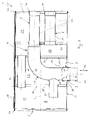
- a muffler 1 comprises two end faces 2 facing away from one another, a jacket 3 which is closed in the circumferential direction, at least one muffler insert 4, at least one inlet pipe 5 and at least one outlet pipe 6.
- the muffler 1 is provided for installation in an exhaust system, not shown, of an internal combustion engine and can be used in particular in a motor vehicle.
- the silencer 1 is a rear silencer, ie the silencer, which is within the exhaust system with respect.
- the muffler is particularly advantageously a muffler arranged transversely in the mounted state. In the transverse muffler 1, an axial direction 7 of the muffler 1 extends substantially parallel to a horizontal transverse direction of the vehicle.
- At least one of the tubes that is to say at least one inlet tube 5 and / or one outlet tube 6, extends through the jacket 3 into the silencer interior 8.
- exactly one pipe namely the inlet pipe 5, extends through the casing 3.
- more than one outlet pipe 6 may be provided.
- the example of Fig. 1 shows two outlet pipes 6.
- the inlet pipe 5 is the side of the jacket 3 penetrating pipe 5, 6, in another embodiment with opposite flow direction and the Outlet pipe 6, the laterally the jacket 3 penetrating pipe 5, 6 be.
- both at least one inlet pipe 5 and at least one outlet pipe 6 are arranged laterally and penetrate the jacket 3.
- all the inlet and outlet pipes 5, 6 can be connected laterally to the casing 3.
- the inlet pipe 5 is fixed to the jacket 3.
- at least one welded joint 9 is provided with which the inlet pipe 5 is fastened to the casing 3. This may be e.g. to act around a circular closed circumferential weld, creating a gas-tight connection is created at the same time.
- the inlet pipe 5 it is also possible e.g. in the manufacture of the muffler 1, the inlet pipe 5 to be fixed by means of at least one welding point or a staple on the jacket 3.
- a corresponding feed pipe 29 can be connected to the inlet pipe 5.
- a circumferential weld can be generated. Preference is then given to the attachment of a three-cut seam, which simultaneously three sheets, so here the inlet tube 5, the jacket 3 and the feed tube 29 connects to each other.
- the inlet pipe 5 passes through an opening 17 incorporated laterally into the casing 3.
- the respective welded connection 9 can be formed at an end face of an outwardly projecting collar 18 which surrounds the opening 17.
- the inlet pipe 5 has a cone 10, which engages with a complementary or complementarily shaped counter-cone 11, which is provided on the muffler insert 4.
- a complementary or complementarily shaped counter-cone 11 which is provided on the muffler insert 4.
- the inlet tube 5 is supported on the one hand on the jacket 3 and on the other hand, spaced over the engaging cone 11 in the cone 11 on the muffler insert 4.
- the inlet tube 5 can absorb moments and support the forces occurring during operation without further notice.
- the inlet pipe 5 is mounted in such a way that it is supported on the muffler insert 4 under an axial pretensioning with respect to the pipe longitudinal axis 12.
- This axial preload is in Fig. 1 indicated by a double arrow and denoted by 13.
- the axial prestress 13 acts between the muffler insert 4 and the jacket 3 and is transmitted via the inlet pipe 5 between the jacket 3 and the muffler insert 4.
- the inlet tube 5 engages with its cone 10 under the axial bias 13 in the counter-cone 11 a.
- the axial preload 13 is not chosen arbitrarily, but has a predetermined value.
- the axial preload 13 can be deliberately set so large that an axial minimum preload for the entire during operation of the muffler guaranteed to the expected temperature range.
- the thermal operating range can range in a vehicle application, for example. From -40 ° C to + 500 ° C, if it is a rear silencer.
- the cone 10 is expediently integrally formed on the inlet tube 5.
- the inner end of the inlet tube 5 is converted to produce the cone 10. Basically, however, a built variant is possible.
- the counter-cone 11 is formed on an intermediate tube 14 of the muffler insert 4.
- This intermediate tube 14 is attached here to an intermediate bottom 15 of the muffler insert 4, which is arranged between the two end floors 2.
- the counter-cone 11 is formed integrally on the intermediate tube 14.
- the intermediate tube 14 is configured so that it is resilient in the region of the mating cone 11 in the tube longitudinal axis 12 resiliently. This resilient compliance facilitates the generation of the axial preload 13.
- the intermediate tube 14 is tensioned like a spring to produce the bias voltage 13.
- the intermediate tube 14 is designed with a comparatively high spring rigidity or stability. This can be realized, for example, in that the intermediate tube 14 is curved as in the example shown and is supported on two intermediate floors 15 and 30.
- the jacket 3 is formed by winding a sheet metal part. Accordingly, this is a manufactured in the winding construction muffler 1.
- the jacket 3 have a longitudinal fold 16 which is parallel to the Silencer longitudinal axis 7 extends.
- the longitudinal fold 16 is positioned on a side facing away from the inlet pipe 5 side.
- At least one of the end floors 2, here in Fig. 1 right end bottom 2, may be part of the muffler insert 4.
- the muffler insert 4 is axially, that is used parallel to the muffler longitudinal axis 7 and thus the front side in the shell 3. It may be expediently provided to match the outer dimension of the insert 4 and the inner dimension of the shell 3 so that the muffler insert 4 relative to the longitudinal axis of the muffler 7 rests or is held under radial bias on the casing 3.
- the respective outlet pipe 6 extends through one of the end floors 2, here by the in Fig. 1 Right end 2 shown on the right, which belongs to the silencer insert 4 in the example.
- the respective outlet pipe 6 extends in the example by a further intermediate bottom 31, which is also provided here for positioning and stabilization of the intermediate tube 14.
- the respective outlet pipe 6 is fastened at least to the end floor 2, for example by means of a welded connection 20 in order to realize a gas-tight connection here as well.
- the end floors 2 are attached axially to the jacket 3 and inserted therein and fixedly connected to the jacket 2, z. B. with a circumferential fold joint 21st
- Corresponding Fig. 1 can the cone 10 in the circumferential direction of the inlet tube 5 annularly supported on the counter-cone 11 is supported. As a result, in each direction, a radial support of the inlet tube 5 on the muffler insert 4 is possible.
- Fig. 1 can be seen, cone 10 and counter-cone 11 are spaced from the jacket 3. This is achieved by a jacket 3 in the tube longitudinal axis 12 spaced positioning of the free pipe 5 facing the end 19 of the intermediate tube 14 relative to the shell 3. Transversely to the tube longitudinal axis 12, the intermediate tube 14 is supported on the shelves 15, 30. In particular, the intermediate tube 14 is arranged approximately centrally in the silencer interior 8, in relation to the tube longitudinal axis 12.
- the inlet pipe 5 is axially open, so that the exhaust gas through the cone 10 and through the counter-cone 11 can flow into the intermediate tube 14.
- the inlet pipe 5 protrudes through the casing 3 into a space 22 which is formed in the silencer interior 8 with the aid of the silencer insert 4.
- Said space 22 is bounded laterally by the partitions 15, 30 and by a portion of the shell 3.
- the partitions 15, 30, 31 may be designed to be gas-permeable or sound-permeable, for example by means of openings or by means of a perforation.
- one outlet pipe 6 is fluidically connected to the inlet pipe 5 via the intermediate pipe 14 and leads out of the muffler 1.
- At least one of the exit tubes 6 may have a perforation 23 to communicate with a space 24 formed between the intermediate wall 31 and the adjacent end floor 2.
- the intermediate wall 31 may, for example by means of a perforation, gas-permeable or sound permeable be designed to increase the volume of the space 24 to the intermediate floor 15, so that, for example, a space 25 formed between the shelves 15 and 31, eg can be used as adsorption.
- Fig. 1 connects the intermediate pipe 14, the inlet pipe 5 with the one outlet pipe 6.
- the exhaust gas can flow directly and thus without much pressure loss, the muffler 1.
- the intermediate tube 14 is suitably bent.
- the intermediate tube 14 has the intermediate tube 14 a bend of about 90 °. Accordingly, it generates a flow deflection of about 90 °.
- the intermediate tube 14 may according to Fig. 1 be fluidly connected to a branch pipe 26.
- the branch pipe 26 opens into a resonance chamber 32.
- the resonance chamber 32 is limited in the example by the one intermediate bottom 30 and by the adjacent end bottom 2 axially and circumferentially through the jacket 3.
- the resonance chamber 32 can now be fluidically connected to the space 25 via at least one connecting pipe 33, which is also referred to below as the additional space 25.
- a further pipe 34 is connected, which in the example is a further outlet pipe 6.
- exhaust gas from the intermediate pipe 14 via the branch pipe 26 passes through the resonance chamber 32, via the connecting pipe 33 in the additional space 25 and exits via the further outlet pipe 6 and 34 from the muffler 1.
- the space 22, which may also be referred to below as the intermediate space 22, may optionally be coupled sound-transmitting to the resonance space 32 and / or to the additional space 25 and / or to the interior of the connection pipe 33 and / or to the interior of the intermediate pipe 14.
- the respective sound-transmitting connection can be realized for example by means of a perforation 35, which is formed in the intermediate space 30 separating the intermediate space 22 from the resonance space 32.
- a perforation 35 may be formed in the intermediate space 15 separating the intermediate space 22 from the additional space 25.
- the connecting tube 33 may have such a perforation.
- the intermediate tube 14 may have such a perforation 35.
- the exhaust gas flows largely directly from the inlet pipe 5 via the intermediate pipe 14 to the outlet pipe 6 through the muffler 1.
- an increasing additional exhaust gas flow through the branch pipe 26, the connecting pipe 33 and the other outlet 6 can form.
- the cone 10 and the counter cone 11 different configurations or embodiments can be realized.
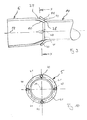
- the cone 10 according to the FIGS. 2 and 6 to 8 have a cone-segment-shaped outer contour 27.
- the outer contour 27 of the cone 10 also be designed spherical segment.
- other shapes for the outer contour 27 are conceivable.
- the counter-cone 11 have a conical-segment-shaped inner contour 28. At coordinated angles and coaxial alignment of the cone 10 and the counter-cone 11, this results in a particularly intensive planar and annularly closed support of the inlet tube 5 on the intermediate tube 14.
- the counter-cone 11 can also be a spherical segment-shaped inner contour 28 according to Fig. 4 or a funnel-shaped inner contour 28 according to Fig. 5 exhibit.
- the funnel-shaped inner contour 28 according to Fig. 5 Characterized in relation to the spherical segment-shaped inner contour 28 Fig. 4 and with respect to the cone-segment-shaped inner contour 28 of the FIGS. 2 and 6 to 8 in that the inner contour 28 has a curved profile which is convex toward the cone 10.
- FIGS. 3 to 5 meets a cone 10 with spherical segment-shaped outer contour 27 on a cone-segment-shaped inner contour 28 (FIG. Fig. 3 ) or on a spherical segment-shaped inner contour 28 (FIG. Fig. 4 ) or on a funnel-shaped inner contour 28 ( Fig. 5 ) of the counter-cone 11.
- it also comes to a circumferentially closed linear contact between cone 10 and counter-cone 11, if no exact coaxial alignment between the cone 10 and counter-cone 11 is present.
- a spherical segment-shaped outer contour 27 of the cone 10 cooperates with a conical-segment-shaped inner contour 28 of the mating cone 11.
- This embodiment can be realized comparatively inexpensively.
- the cone 10 is formed in each case at an inner end of the inlet tube 5. Furthermore, in the embodiments of the Fig. 1 to 6 the counter-cone 11 is formed in each case at an end 19 of the intermediate tube 14 facing the inlet tube 5.
- the cone 10 is formed between an inboard end portion 36 of the inlet tube 5 and a portion 37 of the inlet tube 5 fixed to the shell 3. Accordingly, in these embodiments, the cone 10 is positioned at a distance from the inner axial end of the inlet tube 5.
- the end portion 36 which projects axially beyond the cone 10, forms a plug-in portion which can be inserted into the intermediate tube 14 through the counter-cone 11.
- the outer dimension of the end portion 36 and the inner dimension of the intermediate tube 14 may be so matched to each other that sets only a little play or no play or even a press fit.
- the counter-cone 11 is arranged at a distance from the inlet tube 5 facing the end 19 of the intermediate tube 14 in these embodiments.
- the over the counter-cone 11 axially projecting end portion 38 of the intermediate tube 14 is so measured that it can be plugged onto the inlet tube 5 from the outside.
- the inlet tube 5 is inserted with its cone 10 in the end portion 38 of the intermediate tube 14 in order to come into engagement with the mating cone 11.
- the outer dimension of the inlet tube 5 and the inner dimension of the end portion 38 can be adjusted to one another in such a way that a slight radial clearance or no radial clearance or even an interference fit is formed.
- This measure also leads to a stiffening of the coupling between inlet tube 5 and intermediate tube 14, which improves the radial support of the inlet tube 5 via the intermediate tube 14 on the muffler insert 14.
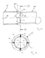
- the cone 10 may have a plurality of projections 40 distributed in the circumferential direction, which protrude outward in relation to the remaining outer contour 27.
- the cone 10 is supported at the counter cone 11 from.
- through openings 41 can thereby form in the circumferential direction between the projections 40.
- exactly four such projections 40 are provided by way of example only, which are also arranged distributed symmetrically in the circumferential direction. It will be understood that there are at least three such protrusions 40, with the number of protrusions 40 being suitably limited to fifteen or ten.
- FIGS. 11 and 12 may be formed according to another option on the cone 10 a plurality of circumferentially spaced slots 42 which each extend axially and which are each open on one side and divide the cone 10 in the circumferential direction into a plurality of cone segments 43.
- the slots 42 separate the cone segments 43 from each other in the circumferential direction.
- the mating cone 11 may also be provided with such slots distributed in the circumferential direction, extending axially, axially open on one side, and dividing the mating cone 11 in the circumferential direction into a plurality of mating cone segments.
- FIGS. 11 and 12 are formed without restriction of generality exactly four such slots 42, which are also arranged symmetrically distributed. It is clear that more or less than four such slots 42 can be realized.
- a projection 40 may be arranged in the circumferential direction between two adjacent slots 42 on the respective cone segment 43.
- the in the Fig. 9 until 12 presented measures with the in the Fig. 2 to 8 combine presented configurations.
- the projections 40 and the slots 42 simplify tolerance compensation and improve the support effect between the cone 10 and the counter-cone 11.
- the inlet tube 5 is inserted as far as through the opening 17 in the muffler interior 8 before attaching the inlet tube 5 on the jacket 3, until the inlet tube 5 via the engaging with the mating cone 11 cone 10 with the axial bias 13, in particular with the predetermined axial preload 13, is supported on the muffler insert 4.
- the attachment of the inlet pipe 5 on the jacket 3, ie in particular the attachment of the welded joint 9, then takes place with maintained axial prestress 13, that is, while the inlet pipe 5 is axially prestressed supported on the muffler insert 4.
- the previously, in particular targeted, applied bias 13 can be preserved.
Landscapes
- Engineering & Computer Science (AREA)
- Chemical & Material Sciences (AREA)
- Combustion & Propulsion (AREA)
- Mechanical Engineering (AREA)
- General Engineering & Computer Science (AREA)
- Exhaust Silencers (AREA)
Claims (13)
- Silencieux pour une installation de gaz d'échappement d'un moteur à combustion interne, notamment d'un véhicule automobile,- comportant deux fonds d'extrémité (2) frontaux de détournant l'un de l'autre,- comportant une gaine (3) circonférentielle fermée dans la direction circonférentielle,- comportant au moins un insert de silencieux (4),- comportant au moins un tuyau d'admission (5),- comportant au moins un tuyau d'échappement (6),- dans lequel au moins un des tuyaux (5,6) s'étend à travers la gaine (3) dans l'intérieur du silencieux (8) et est fixé sur la gaine (3), caractérisé en ce que- le tuyau (5,6) s'étendant à travers la gaine (3) présente un cône (10),- l'insert de silencieux (4) présente un tuyau intermédiaire (14), qui présente un cône opposé (11),- le cône (10) et le contre-cône (11) viennent en prise l'un dans l'autre.
- Silencieux selon la revendication 1, caractérisé en ce que le tuyau (5,6) s'étendant à travers la gaine (3) est monté de telle sorte qu'il soit appuyé sous une précontrainte axiale (13) sur l'insert de silencieux (4) par l'intermédiaire du cône (10) coopérant avec le cône opposé (11).
- Silencieux selon la revendication 2, caractérisé en ce que le tuyau respectif (5,6) s'appuie sous une précontrainte (13) axiale prédéterminée sur l'insert de silencieux (4), qui peut être notamment choisie de telle sorte que par l'intermédiaire de la plage de fonctionnement thermique totale à escompter du silencieux (1) une précontrainte axiale minimale reste conservée.
- Silencieux selon une des revendications 1 à 3, caractérisé en ce que- le cône (10) vient en prise dans le cône opposé (11) ou inversement, et/ou- le cône (10) présente un contour extérieur (27) ou un contour intérieur en forme de segment conique ou en forme de segment sphérique, et/ou- le cône opposé (11) présente un contour intérieur (28) ou un contour extérieur en forme de segment conique ou en forme de segment sphérique ou en forme de trémie,- le cône opposé (11) est de forme complémentaire au cône (10).
- Silencieux selon une des revendications 1 à 4, caractérisé en ce que- le cône (10) est façonné en un seul tenant sur le tuyau respectif (5,6), et/ou- le cône opposé (11) est façonné en un seul tenant sur le tuyau intermédiaire (14).
- Silencieux selon une des revendications 1 à 5, caractérisé en ce que- le tuyau intermédiaire (14) est conçu et/ou monté de telle sorte qu'il soit résilient avec ressort élastique au niveau du cône opposé (11) parallèlement à l'axe longitudinal (12) du tuyau (5,6) présentant le cône (10), et/ou- le tuyau intermédiaire (14) est arqué et génère une déviation d'écoulement de 90°.
- Silencieux selon une des revendications 1 à 6, caractérisé en ce que- le tuyau intermédiaire (14) relie fluidiquement le tuyau d'admission (5) au tuyau d'échappement (6), et/ou- le tuyau intermédiaire (14) est relié fluidiquement à un tuyau d'embranchement (26), qui débouche dans une chambre de résonance (32), et/ou- la chambre de résonance (32) est reliée fluidiquement par l'intermédiaire d'au moins un tuyau de liaison (33) à une chambre supplémentaire (25), et/ou- la chambre supplémentaire (25) est reliée fluidiquement à un autre tuyau (34), qui peut aussi être un tuyau d'échappement (6), et/ou- le tuyau intermédiaire (14) et/ou la chambre supplémentaire (25) et/ou la chambre de résonance (32) et/ou le tuyau de liaison (33) est/sont reliés de manière transmettant les sons à une chambre intermédiaire (22), à l'intérieur de laquelle saille le tuyau (5,6) traversant la gaine (3).
- Silencieux selon une des revendications 1 à 7, caractérisé en ce que- le cône (10) est réalisé sur une extrémité située à l'intérieur du tuyau (5,6) traversant la gaine (3) ou entre une portion d'extrémité située à l'intérieur (36) du tuyau (5,6)traversant la gaine (3) et une portion (37) de ce tuyau (5,6) fixée sur la gaine (3), dans lequel il peut notamment être prévu que la portion d'extrémité (36) plonge par l'intermédiaire du cône opposé (11) dans le tuyau intermédiaire (14) ou en ce que le cône opposé (11) est enfiché dans cette portion d'extrémité (36), et/ou- le cône opposé (11) est réalisé dans une extrémité (19) du tuyau intermédiaire (14) tournée vers le tuyau respectif (5,6) ou entre une portion d'extrémité (38) du tuyau intermédiaire (14) tournée vers un des tuyaux respectifs (5,6) et une portion (39) du tuyau intermédiaire (14) fixée sur l'insert de silencieux (4), dans lequel il peut notamment être prévu que le cône (10) soit enfiché dans cette portion d'extrémité (38) ou que cette portion d'extrémité (38) plonge par l'intermédiaire du cône (10) dans le tuyau respectif (5, 6) .
- Silencieux selon une des revendications 1 à 8, caractérisé en ce que- la gaine (3) est formée par enroulement d'une pièce de tôle, et/ou- la gaine (3) présente un pli longitudinal (16), qui se trouve notamment sur un côté qui se détourne du tuyau (5,6) traversant la gaine (3), et/ou- au moins un des fonds d'extrémité (2) forme une partie intégrante de l'insert de silencieux (4), et/ou- l'insert de silencieux (4) est inséré du côté frontal dans la gaine (3), et/ou- la gaine (3) vient reposer avec précontrainte sur l'insert de silencieux (4), et/ou- au moins un autre des tuyaux (5,6) s'étend à travers un des fonds d'extrémité (2) et est fixé sur le fond d'extrémité (2).
- Silencieux selon une des revendications 1 à 9, caractérisé en ce que- le cône (10) s'appuie dans la direction circonférentielle du tuyau respectif (5,6) en forme d'anneau fermé sur le cône opposé (11), et/ou- le cône (10) et le cône opposé (11) sont espacés de la gaine (3), et/ou- le tuyau respectif (5,6) est relié fluidiquement par l'intermédiaire du cône (10) et par l'intermédiaire du cône opposé (11) à l'intérieur du silencieux (8), notamment avec une chambre (22) réalisée à l'intérieur du silencieux (8) à travers l'insert de silencieux (4).
- Silencieux selon une des revendications 1 à 10, caractérisé en ce que- le cône (10) présente plusieurs protubérances (40) réparties dans la direction circonférentielle, par l'intermédiaire desquelles le cône (10) est appuyé sur le cône opposé (11), de telle sorte que notamment dans la direction circonférentielle entre les protubérances (40) des ouvertures de passage (41) entre le cône (10) et le cône opposé (11) restent découvertes, et/ou- le cône opposé (11) présente plusieurs protubérances réparties dans la direction circonférentielle, par l'intermédiaire desquelles le cône opposé (11) est appuyé sur le cône (10), de telle sorte que notamment dans la direction circonférentielle entre les protubérances des ouvertures de passage entre le cône (10) et le cône opposé (11) restent découvertes, et/ou- le cône (10) présente plusieurs fentes (42) réparties dans la direction circonférentielle, qui s'étendent axialement, qui sont ouvertes axialement d'un côté et séparent plusieurs segments coniques (43) l'un de l'autre dans la direction circonférentielle, et/ou- le cône opposé (11) présente plusieurs fentes départies dans la direction circonférentielle, qui s'étendent axialement, qui sont ouvertes axialement d'un côté et qui séparent plusieurs segments coniques opposés l'un de 'l'autre dans la direction circonférentielle.
- Procédé de fabrication d'un silencieux (1) pour une installation de gaz d'échappement d'un moteur à combustion interne, notamment d'un véhicule automobile,- dans lequel au moins un insert de silencieux (4) est glissé frontalement dans une gaine (3) circonférentielle fermée dans la direction circonférentielle,- dans lequel au moins un tuyau (5,6) est enfiché latéralement dans une ouverture (17) de la gaine (3) jusqu'au point où un cône (10) sur l'extrémité précédente du tuyau (5,6) et un cône opposé (11) réalisé sur un tuyau intermédiaire (14) de l'insert de silencieux (4) viennent en prise l'un dans l'autre,- dans lequel le tuyau respectif (5,6) est fixé sur la gaine (3).
- Procédé selon la revendication 12, caractérisé en ce que- le tuyau respectif (5,6) est enfiché jusqu'au point où le tuyau (5,6) est appuyé par l'intermédiaire du cône (10) coopérant avec le cône opposé (11) avec une précontrainte axiale (13) sur l'insert de silencieux (4),- le tuyau respectif (5,6) est fixé sur la gaine (3), pendant qu'il est appuyé axialement avec précontrainte sur l'insert de silencieux (4).
Applications Claiming Priority (1)
| Application Number | Priority Date | Filing Date | Title |
|---|---|---|---|
| DE102010019959A DE102010019959A1 (de) | 2010-05-08 | 2010-05-08 | Schalldämpfer |
Publications (2)
| Publication Number | Publication Date |
|---|---|
| EP2385225A1 EP2385225A1 (fr) | 2011-11-09 |
| EP2385225B1 true EP2385225B1 (fr) | 2014-10-29 |
Family
ID=44189197
Family Applications (1)
| Application Number | Title | Priority Date | Filing Date |
|---|---|---|---|
| EP11157294.7A Active EP2385225B1 (fr) | 2010-05-08 | 2011-03-08 | Silencieux |
Country Status (4)
| Country | Link |
|---|---|
| US (1) | US8292026B2 (fr) |
| EP (1) | EP2385225B1 (fr) |
| CN (1) | CN102235222B (fr) |
| DE (1) | DE102010019959A1 (fr) |
Families Citing this family (28)
| Publication number | Priority date | Publication date | Assignee | Title |
|---|---|---|---|---|
| DE102010062569A1 (de) * | 2010-12-07 | 2012-06-14 | J. Eberspächer GmbH & Co. KG | Gehäuse |
| DE102011077183B4 (de) * | 2011-06-08 | 2015-05-21 | Eberspächer Exhaust Technology GmbH & Co. KG | Schalldämpfer und Herstellungsverfahren |
| US8602157B2 (en) * | 2011-11-03 | 2013-12-10 | Don Emler | Q4 muffler assembly |
| KR20130073710A (ko) * | 2011-12-23 | 2013-07-03 | 삼성전자주식회사 | 연료 전지 시스템의 소음을 저감하기 위한 소음기 |
| US9188048B2 (en) * | 2012-12-20 | 2015-11-17 | Bombardier Recreational Products Inc. | Vehicle having an auxiliary exhaust pipe |
| EP2944784B1 (fr) * | 2013-01-11 | 2017-11-01 | Futaba Industrial Co. Ltd. | Procédé de montage de tube d'entrée et procédé de support de tube d'entrée |
| US8985271B1 (en) * | 2013-10-24 | 2015-03-24 | Kawasaki Jukogyo Kabushiki Kaisha | Exhaust muffler for vehicle |
| US8985272B1 (en) * | 2013-10-24 | 2015-03-24 | Kawasaki Jukogyo Kabushiki Kaisha | Exhaust muffler for vehicle |
| DE102014110098A1 (de) | 2014-07-18 | 2016-01-21 | Friedrich Boysen Gmbh & Co. Kg | Schalldämpfer |
| DE102014217058A1 (de) * | 2014-08-27 | 2016-03-03 | Eberspächer Exhaust Technology GmbH & Co. KG | Schalldämpfer |
| DE102014221151B4 (de) * | 2014-10-17 | 2022-12-08 | Purem GmbH | Komponente einer Abgasanlage |
| DE102015113159A1 (de) * | 2015-08-10 | 2017-02-16 | Faurecia Emissions Control Technologies, Germany Gmbh | Bauteil einer Abgasanlage |
| US10196947B2 (en) | 2016-02-02 | 2019-02-05 | Kohler Co. | Muffler |
| DE102016114317A1 (de) * | 2016-08-03 | 2018-02-08 | Friedrich Boysen Gmbh & Co. Kg | Baueinheit für eine Abgasanlage |
| CN106351712B (zh) * | 2016-10-14 | 2018-08-28 | 上海天纳克排气系统有限公司 | 消声器 |
| EP3431732B1 (fr) | 2017-07-21 | 2020-04-22 | Bosal Emission Control Systems NV | Procédé de formation d'un collier dans un boîtier de silencieux |
| DE102018124198A1 (de) | 2017-10-05 | 2019-04-11 | Tenneco Automotive Operating Company Inc. | Akustisch abgestimmter Schalldämpfer |
| US11365658B2 (en) | 2017-10-05 | 2022-06-21 | Tenneco Automotive Operating Company Inc. | Acoustically tuned muffler |
| US11199116B2 (en) * | 2017-12-13 | 2021-12-14 | Tenneco Automotive Operating Company Inc. | Acoustically tuned muffler |
| JP6822985B2 (ja) * | 2018-01-05 | 2021-01-27 | フタバ産業株式会社 | 消音装置 |
| US10882578B2 (en) * | 2018-06-13 | 2021-01-05 | Magnum Shielding Corporation | Increasing the internal pivot radii for angle-joined motorcycle handle bars |
| CN109057917A (zh) * | 2018-09-27 | 2018-12-21 | 上海天纳克排气系统有限公司 | 消音器 |
| US11268429B2 (en) * | 2019-01-17 | 2022-03-08 | Tenneco Automotive Operating Company Inc. | Diffusion surface alloyed metal exhaust component with inwardly turned edges |
| US11268430B2 (en) * | 2019-01-17 | 2022-03-08 | Tenneco Automotive Operating Company Inc. | Diffusion surface alloyed metal exhaust component with welded edges |
| US10975743B1 (en) | 2020-03-13 | 2021-04-13 | Tenneco Automotive Operating Company Inc. | Vehicle exhaust component |
| CN213747266U (zh) * | 2020-09-27 | 2021-07-20 | 珠海华宇金属有限公司 | 空调消音器 |
| DE102021114254A1 (de) * | 2021-06-02 | 2022-12-08 | Purem GmbH | Schalldämpfer und Verfahren zur Herstellung eines Schalldämpfers |
| DE102021115962A1 (de) * | 2021-06-21 | 2022-12-22 | Purem GmbH | Schalldämpfer und Verfahren zur Herstellung eines Schalldämpfers |
Family Cites Families (16)
| Publication number | Priority date | Publication date | Assignee | Title |
|---|---|---|---|---|
| US4076099A (en) * | 1976-04-05 | 1978-02-28 | Caterpillar Tractor Co. | Device for reducing engine exhaust noise |
| US4501341A (en) * | 1981-03-12 | 1985-02-26 | Jones Adrian D | Low frequency muffler |
| GB2303315B (en) * | 1993-01-11 | 1997-07-30 | Fuji Heavy Ind Ltd | Engine exhaust apparatus |
| DE19508217A1 (de) * | 1995-03-08 | 1996-09-12 | Emitec Emissionstechnologie | Metallischer Wabenkörper |
| US7367418B2 (en) * | 2002-11-07 | 2008-05-06 | Arctic Cat Inc. | Snowmobile air box assembly |
| CA2443427A1 (fr) * | 2003-09-30 | 2005-03-30 | Tom Tary | Silencieux |
| US7077922B2 (en) * | 2003-07-02 | 2006-07-18 | Owens Corning Composites S.P.R.L. | Technique to fill silencers |
| DE102005002857B4 (de) * | 2005-01-20 | 2007-08-30 | J. Eberspächer GmbH & Co. KG | Baukastensystem für eine Abgasbehandlungsvorrichtung |
| DE102005026376C5 (de) * | 2005-06-08 | 2019-05-02 | Faurecia Emissions Control Technologies, Germany Gmbh | Fahrzeugschalldämpfer |
| US7870930B2 (en) * | 2005-09-02 | 2011-01-18 | Emcon Technologies Llc | Exhaust system with external helmholtz resonator and associated method |
| WO2008018821A1 (fr) * | 2006-08-11 | 2008-02-14 | Volvo Construction Equipment Ab | Dispositif pour atténuer et/ou diriger le son, et machine |
| JP2008111356A (ja) * | 2006-10-30 | 2008-05-15 | Yamaha Motor Co Ltd | 自動二輪車の排気装置及び該排気装置を備えた自動二輪車 |
| DE102007011956A1 (de) * | 2007-03-09 | 2008-09-11 | J. Eberspächer GmbH & Co. KG | Abgasbehandlungseinrichtung und zugehöriges Herstellungsverfahren |
| BRPI0812314A2 (pt) * | 2007-05-30 | 2014-11-25 | Yamaha Motor Co Ltd | Dispositivo de exaustão e veículo do tipo de montar |
| US7942239B2 (en) * | 2007-07-10 | 2011-05-17 | Tmg Performance Products, Llc | Exhaust muffler |
| US8251173B2 (en) * | 2009-07-23 | 2012-08-28 | Briggs & Stratton Corporation | Muffler attachment system |
-
2010
- 2010-05-08 DE DE102010019959A patent/DE102010019959A1/de not_active Withdrawn
-
2011
- 2011-03-08 EP EP11157294.7A patent/EP2385225B1/fr active Active
- 2011-05-05 US US13/101,365 patent/US8292026B2/en active Active
- 2011-05-06 CN CN201110116664.0A patent/CN102235222B/zh active Active
Also Published As
| Publication number | Publication date |
|---|---|
| CN102235222A (zh) | 2011-11-09 |
| CN102235222B (zh) | 2015-05-13 |
| US20110272209A1 (en) | 2011-11-10 |
| EP2385225A1 (fr) | 2011-11-09 |
| US8292026B2 (en) | 2012-10-23 |
| DE102010019959A1 (de) | 2011-11-10 |
Similar Documents
| Publication | Publication Date | Title |
|---|---|---|
| EP2385225B1 (fr) | Silencieux | |
| EP2354483B1 (fr) | Silencieux | |
| DE102011077183B4 (de) | Schalldämpfer und Herstellungsverfahren | |
| DE102005026376B4 (de) | Fahrzeugschalldämpfer | |
| DE102014215084B4 (de) | Injektionseinrichtung und zugehöriges Herstellungsverfahren | |
| EP1832726B1 (fr) | Composant pour un dispositif d'échappement | |
| DE102008056350B4 (de) | Schalldämpfer und zugehöriges Herstellungsverfahren | |
| DE102009014433A1 (de) | Abgasbehandlungseinrichtung | |
| EP2075432B1 (fr) | Collecteur de gaz d'échappement et son procédé de fabrication | |
| EP1627997B1 (fr) | Silencieux d'échappement et méthode de fabrication | |
| EP2362076A2 (fr) | Amortisseur de bruit | |
| DE10360645A1 (de) | Auspuffkrümmer | |
| EP3009623B1 (fr) | Composant pour une installation de gaz d'échappement et fixation pour ce composant | |
| EP2643569B1 (fr) | Silencieux | |
| DE102012204114A1 (de) | Schalldämpfer-Einheit | |
| WO2020148129A1 (fr) | Procédé de fabrication d'un silencieux, silencieux et véhicule | |
| EP3245396B1 (fr) | Silenciux pour vehicule | |
| EP1726794A1 (fr) | Silencieux d'échappement et procédé de fabrication | |
| EP2616649A1 (fr) | Unité de traitement de gaz d'échappement pour une conduite de recyclage de gaz d'échappement | |
| DE102015223680A1 (de) | Schalldämpfer | |
| DE102017100133A1 (de) | Wärmetauschergehäuse | |
| WO2020148124A1 (fr) | Silencieux destiné à une ligne d'échappement d'un véhicule à moteur et son procédé de fabrication | |
| DE102004042110B3 (de) | Schalldämpfer für eine Abgasanlage | |
| DE102019204072A1 (de) | Geräuschdämpfer für einen Ansaugtrakt | |
| DE9417244U1 (de) | Schalldämpfer, insbesondere Resonator-Schalldämpfer, Katalysator o.dgl. |
Legal Events
| Date | Code | Title | Description |
|---|---|---|---|
| AK | Designated contracting states |
Kind code of ref document: A1 Designated state(s): AL AT BE BG CH CY CZ DE DK EE ES FI FR GB GR HR HU IE IS IT LI LT LU LV MC MK MT NL NO PL PT RO RS SE SI SK SM TR |
|
| AX | Request for extension of the european patent |
Extension state: BA ME |
|
| PUAI | Public reference made under article 153(3) epc to a published international application that has entered the european phase |
Free format text: ORIGINAL CODE: 0009012 |
|
| 17P | Request for examination filed |
Effective date: 20120509 |
|
| RAP1 | Party data changed (applicant data changed or rights of an application transferred) |
Owner name: EBERSPAECHER EXHAUST TECHNOLOGY GMBH & CO. KG |
|
| GRAP | Despatch of communication of intention to grant a patent |
Free format text: ORIGINAL CODE: EPIDOSNIGR1 |
|
| RIC1 | Information provided on ipc code assigned before grant |
Ipc: F01N 1/08 20060101AFI20140703BHEP Ipc: F01N 13/18 20100101ALI20140703BHEP |
|
| INTG | Intention to grant announced |
Effective date: 20140801 |
|
| GRAS | Grant fee paid |
Free format text: ORIGINAL CODE: EPIDOSNIGR3 |
|
| GRAA | (expected) grant |
Free format text: ORIGINAL CODE: 0009210 |
|
| AK | Designated contracting states |
Kind code of ref document: B1 Designated state(s): AL AT BE BG CH CY CZ DE DK EE ES FI FR GB GR HR HU IE IS IT LI LT LU LV MC MK MT NL NO PL PT RO RS SE SI SK SM TR |
|
| REG | Reference to a national code |
Ref country code: GB Ref legal event code: FG4D Free format text: NOT ENGLISH |
|
| REG | Reference to a national code |
Ref country code: CH Ref legal event code: EP |
|
| REG | Reference to a national code |
Ref country code: AT Ref legal event code: REF Ref document number: 693728 Country of ref document: AT Kind code of ref document: T Effective date: 20141115 |
|
| REG | Reference to a national code |
Ref country code: IE Ref legal event code: FG4D Free format text: LANGUAGE OF EP DOCUMENT: GERMAN |
|
| REG | Reference to a national code |
Ref country code: DE Ref legal event code: R096 Ref document number: 502011004799 Country of ref document: DE Effective date: 20141211 |
|
| REG | Reference to a national code |
Ref country code: NL Ref legal event code: VDEP Effective date: 20141029 |
|
| REG | Reference to a national code |
Ref country code: LT Ref legal event code: MG4D |
|
| PG25 | Lapsed in a contracting state [announced via postgrant information from national office to epo] |
Ref country code: NL Free format text: LAPSE BECAUSE OF FAILURE TO SUBMIT A TRANSLATION OF THE DESCRIPTION OR TO PAY THE FEE WITHIN THE PRESCRIBED TIME-LIMIT Effective date: 20141029 Ref country code: FI Free format text: LAPSE BECAUSE OF FAILURE TO SUBMIT A TRANSLATION OF THE DESCRIPTION OR TO PAY THE FEE WITHIN THE PRESCRIBED TIME-LIMIT Effective date: 20141029 Ref country code: IS Free format text: LAPSE BECAUSE OF FAILURE TO SUBMIT A TRANSLATION OF THE DESCRIPTION OR TO PAY THE FEE WITHIN THE PRESCRIBED TIME-LIMIT Effective date: 20150228 Ref country code: NO Free format text: LAPSE BECAUSE OF FAILURE TO SUBMIT A TRANSLATION OF THE DESCRIPTION OR TO PAY THE FEE WITHIN THE PRESCRIBED TIME-LIMIT Effective date: 20150129 Ref country code: PT Free format text: LAPSE BECAUSE OF FAILURE TO SUBMIT A TRANSLATION OF THE DESCRIPTION OR TO PAY THE FEE WITHIN THE PRESCRIBED TIME-LIMIT Effective date: 20150302 Ref country code: LT Free format text: LAPSE BECAUSE OF FAILURE TO SUBMIT A TRANSLATION OF THE DESCRIPTION OR TO PAY THE FEE WITHIN THE PRESCRIBED TIME-LIMIT Effective date: 20141029 Ref country code: ES Free format text: LAPSE BECAUSE OF FAILURE TO SUBMIT A TRANSLATION OF THE DESCRIPTION OR TO PAY THE FEE WITHIN THE PRESCRIBED TIME-LIMIT Effective date: 20141029 |
|
| PG25 | Lapsed in a contracting state [announced via postgrant information from national office to epo] |
Ref country code: HR Free format text: LAPSE BECAUSE OF FAILURE TO SUBMIT A TRANSLATION OF THE DESCRIPTION OR TO PAY THE FEE WITHIN THE PRESCRIBED TIME-LIMIT Effective date: 20141029 Ref country code: SE Free format text: LAPSE BECAUSE OF FAILURE TO SUBMIT A TRANSLATION OF THE DESCRIPTION OR TO PAY THE FEE WITHIN THE PRESCRIBED TIME-LIMIT Effective date: 20141029 Ref country code: LV Free format text: LAPSE BECAUSE OF FAILURE TO SUBMIT A TRANSLATION OF THE DESCRIPTION OR TO PAY THE FEE WITHIN THE PRESCRIBED TIME-LIMIT Effective date: 20141029 Ref country code: RS Free format text: LAPSE BECAUSE OF FAILURE TO SUBMIT A TRANSLATION OF THE DESCRIPTION OR TO PAY THE FEE WITHIN THE PRESCRIBED TIME-LIMIT Effective date: 20141029 Ref country code: CY Free format text: LAPSE BECAUSE OF FAILURE TO SUBMIT A TRANSLATION OF THE DESCRIPTION OR TO PAY THE FEE WITHIN THE PRESCRIBED TIME-LIMIT Effective date: 20141029 Ref country code: GR Free format text: LAPSE BECAUSE OF FAILURE TO SUBMIT A TRANSLATION OF THE DESCRIPTION OR TO PAY THE FEE WITHIN THE PRESCRIBED TIME-LIMIT Effective date: 20150130 Ref country code: PL Free format text: LAPSE BECAUSE OF FAILURE TO SUBMIT A TRANSLATION OF THE DESCRIPTION OR TO PAY THE FEE WITHIN THE PRESCRIBED TIME-LIMIT Effective date: 20141029 |
|
| REG | Reference to a national code |
Ref country code: DE Ref legal event code: R097 Ref document number: 502011004799 Country of ref document: DE |
|
| PG25 | Lapsed in a contracting state [announced via postgrant information from national office to epo] |
Ref country code: DK Free format text: LAPSE BECAUSE OF FAILURE TO SUBMIT A TRANSLATION OF THE DESCRIPTION OR TO PAY THE FEE WITHIN THE PRESCRIBED TIME-LIMIT Effective date: 20141029 Ref country code: SK Free format text: LAPSE BECAUSE OF FAILURE TO SUBMIT A TRANSLATION OF THE DESCRIPTION OR TO PAY THE FEE WITHIN THE PRESCRIBED TIME-LIMIT Effective date: 20141029 Ref country code: EE Free format text: LAPSE BECAUSE OF FAILURE TO SUBMIT A TRANSLATION OF THE DESCRIPTION OR TO PAY THE FEE WITHIN THE PRESCRIBED TIME-LIMIT Effective date: 20141029 Ref country code: RO Free format text: LAPSE BECAUSE OF FAILURE TO SUBMIT A TRANSLATION OF THE DESCRIPTION OR TO PAY THE FEE WITHIN THE PRESCRIBED TIME-LIMIT Effective date: 20141029 Ref country code: CZ Free format text: LAPSE BECAUSE OF FAILURE TO SUBMIT A TRANSLATION OF THE DESCRIPTION OR TO PAY THE FEE WITHIN THE PRESCRIBED TIME-LIMIT Effective date: 20141029 |
|
| PLBE | No opposition filed within time limit |
Free format text: ORIGINAL CODE: 0009261 |
|
| STAA | Information on the status of an ep patent application or granted ep patent |
Free format text: STATUS: NO OPPOSITION FILED WITHIN TIME LIMIT |
|
| 26N | No opposition filed |
Effective date: 20150730 |
|
| PG25 | Lapsed in a contracting state [announced via postgrant information from national office to epo] |
Ref country code: MC Free format text: LAPSE BECAUSE OF FAILURE TO SUBMIT A TRANSLATION OF THE DESCRIPTION OR TO PAY THE FEE WITHIN THE PRESCRIBED TIME-LIMIT Effective date: 20141029 Ref country code: LU Free format text: LAPSE BECAUSE OF FAILURE TO SUBMIT A TRANSLATION OF THE DESCRIPTION OR TO PAY THE FEE WITHIN THE PRESCRIBED TIME-LIMIT Effective date: 20150308 |
|
| REG | Reference to a national code |
Ref country code: CH Ref legal event code: PL |
|
| REG | Reference to a national code |
Ref country code: IE Ref legal event code: MM4A |
|
| PG25 | Lapsed in a contracting state [announced via postgrant information from national office to epo] |
Ref country code: LI Free format text: LAPSE BECAUSE OF NON-PAYMENT OF DUE FEES Effective date: 20150331 Ref country code: CH Free format text: LAPSE BECAUSE OF NON-PAYMENT OF DUE FEES Effective date: 20150331 Ref country code: IE Free format text: LAPSE BECAUSE OF NON-PAYMENT OF DUE FEES Effective date: 20150308 |
|
| PG25 | Lapsed in a contracting state [announced via postgrant information from national office to epo] |
Ref country code: SI Free format text: LAPSE BECAUSE OF FAILURE TO SUBMIT A TRANSLATION OF THE DESCRIPTION OR TO PAY THE FEE WITHIN THE PRESCRIBED TIME-LIMIT Effective date: 20141029 |
|
| REG | Reference to a national code |
Ref country code: FR Ref legal event code: PLFP Year of fee payment: 6 |
|
| PG25 | Lapsed in a contracting state [announced via postgrant information from national office to epo] |
Ref country code: MT Free format text: LAPSE BECAUSE OF FAILURE TO SUBMIT A TRANSLATION OF THE DESCRIPTION OR TO PAY THE FEE WITHIN THE PRESCRIBED TIME-LIMIT Effective date: 20141029 |
|
| REG | Reference to a national code |
Ref country code: FR Ref legal event code: PLFP Year of fee payment: 7 |
|
| REG | Reference to a national code |
Ref country code: AT Ref legal event code: MM01 Ref document number: 693728 Country of ref document: AT Kind code of ref document: T Effective date: 20160308 |
|
| PG25 | Lapsed in a contracting state [announced via postgrant information from national office to epo] |
Ref country code: SM Free format text: LAPSE BECAUSE OF FAILURE TO SUBMIT A TRANSLATION OF THE DESCRIPTION OR TO PAY THE FEE WITHIN THE PRESCRIBED TIME-LIMIT Effective date: 20141029 Ref country code: BG Free format text: LAPSE BECAUSE OF FAILURE TO SUBMIT A TRANSLATION OF THE DESCRIPTION OR TO PAY THE FEE WITHIN THE PRESCRIBED TIME-LIMIT Effective date: 20141029 Ref country code: HU Free format text: LAPSE BECAUSE OF FAILURE TO SUBMIT A TRANSLATION OF THE DESCRIPTION OR TO PAY THE FEE WITHIN THE PRESCRIBED TIME-LIMIT; INVALID AB INITIO Effective date: 20110308 |
|
| PG25 | Lapsed in a contracting state [announced via postgrant information from national office to epo] |
Ref country code: BE Free format text: LAPSE BECAUSE OF NON-PAYMENT OF DUE FEES Effective date: 20150331 |
|
| PG25 | Lapsed in a contracting state [announced via postgrant information from national office to epo] |
Ref country code: TR Free format text: LAPSE BECAUSE OF FAILURE TO SUBMIT A TRANSLATION OF THE DESCRIPTION OR TO PAY THE FEE WITHIN THE PRESCRIBED TIME-LIMIT Effective date: 20141029 Ref country code: AT Free format text: LAPSE BECAUSE OF NON-PAYMENT OF DUE FEES Effective date: 20160308 |
|
| REG | Reference to a national code |
Ref country code: FR Ref legal event code: PLFP Year of fee payment: 8 |
|
| PGFP | Annual fee paid to national office [announced via postgrant information from national office to epo] |
Ref country code: IT Payment date: 20180322 Year of fee payment: 8 |
|
| PG25 | Lapsed in a contracting state [announced via postgrant information from national office to epo] |
Ref country code: MK Free format text: LAPSE BECAUSE OF FAILURE TO SUBMIT A TRANSLATION OF THE DESCRIPTION OR TO PAY THE FEE WITHIN THE PRESCRIBED TIME-LIMIT Effective date: 20141029 |
|
| PG25 | Lapsed in a contracting state [announced via postgrant information from national office to epo] |
Ref country code: AL Free format text: LAPSE BECAUSE OF FAILURE TO SUBMIT A TRANSLATION OF THE DESCRIPTION OR TO PAY THE FEE WITHIN THE PRESCRIBED TIME-LIMIT Effective date: 20141029 |
|
| PG25 | Lapsed in a contracting state [announced via postgrant information from national office to epo] |
Ref country code: IT Free format text: LAPSE BECAUSE OF NON-PAYMENT OF DUE FEES Effective date: 20190308 |
|
| REG | Reference to a national code |
Ref country code: DE Ref legal event code: R081 Ref document number: 502011004799 Country of ref document: DE Owner name: PUREM GMBH, DE Free format text: FORMER OWNER: EBERSPAECHER EXHAUST TECHNOLOGY GMBH & CO. KG, 66539 NEUNKIRCHEN, DE |
|
| PGFP | Annual fee paid to national office [announced via postgrant information from national office to epo] |
Ref country code: FR Payment date: 20230320 Year of fee payment: 13 |
|
| PGFP | Annual fee paid to national office [announced via postgrant information from national office to epo] |
Ref country code: GB Payment date: 20230323 Year of fee payment: 13 Ref country code: DE Payment date: 20230320 Year of fee payment: 13 |