EP2643078B1 - Dreiwegekatalysatorsystem mit einem anströmseitigen mehrschichtkatalysator - Google Patents
Dreiwegekatalysatorsystem mit einem anströmseitigen mehrschichtkatalysator Download PDFInfo
- Publication number
- EP2643078B1 EP2643078B1 EP11790925.9A EP11790925A EP2643078B1 EP 2643078 B1 EP2643078 B1 EP 2643078B1 EP 11790925 A EP11790925 A EP 11790925A EP 2643078 B1 EP2643078 B1 EP 2643078B1
- Authority
- EP
- European Patent Office
- Prior art keywords
- layer
- catalytic
- weight
- catalyst composite
- catalytic layer
- Prior art date
- Legal status (The legal status is an assumption and is not a legal conclusion. Google has not performed a legal analysis and makes no representation as to the accuracy of the status listed.)
- Active
Links
Images

Classifications
-
- B—PERFORMING OPERATIONS; TRANSPORTING
- B01—PHYSICAL OR CHEMICAL PROCESSES OR APPARATUS IN GENERAL
- B01D—SEPARATION
- B01D53/00—Separation of gases or vapours; Recovering vapours of volatile solvents from gases; Chemical or biological purification of waste gases, e.g. engine exhaust gases, smoke, fumes, flue gases, aerosols
- B01D53/34—Chemical or biological purification of waste gases
- B01D53/92—Chemical or biological purification of waste gases of engine exhaust gases
- B01D53/94—Chemical or biological purification of waste gases of engine exhaust gases by catalytic processes
- B01D53/9445—Simultaneously removing carbon monoxide, hydrocarbons or nitrogen oxides making use of three-way catalysts [TWC] or four-way-catalysts [FWC]
- B01D53/945—Simultaneously removing carbon monoxide, hydrocarbons or nitrogen oxides making use of three-way catalysts [TWC] or four-way-catalysts [FWC] characterised by a specific catalyst
-
- B—PERFORMING OPERATIONS; TRANSPORTING
- B01—PHYSICAL OR CHEMICAL PROCESSES OR APPARATUS IN GENERAL
- B01D—SEPARATION
- B01D53/00—Separation of gases or vapours; Recovering vapours of volatile solvents from gases; Chemical or biological purification of waste gases, e.g. engine exhaust gases, smoke, fumes, flue gases, aerosols
- B01D53/34—Chemical or biological purification of waste gases
- B01D53/92—Chemical or biological purification of waste gases of engine exhaust gases
- B01D53/94—Chemical or biological purification of waste gases of engine exhaust gases by catalytic processes
- B01D53/9459—Removing one or more of nitrogen oxides, carbon monoxide, or hydrocarbons by multiple successive catalytic functions; systems with more than one different function, e.g. zone coated catalysts
- B01D53/9463—Removing one or more of nitrogen oxides, carbon monoxide, or hydrocarbons by multiple successive catalytic functions; systems with more than one different function, e.g. zone coated catalysts with catalysts positioned on one brick
- B01D53/9472—Removing one or more of nitrogen oxides, carbon monoxide, or hydrocarbons by multiple successive catalytic functions; systems with more than one different function, e.g. zone coated catalysts with catalysts positioned on one brick in different zones
-
- B—PERFORMING OPERATIONS; TRANSPORTING
- B01—PHYSICAL OR CHEMICAL PROCESSES OR APPARATUS IN GENERAL
- B01D—SEPARATION
- B01D53/00—Separation of gases or vapours; Recovering vapours of volatile solvents from gases; Chemical or biological purification of waste gases, e.g. engine exhaust gases, smoke, fumes, flue gases, aerosols
- B01D53/34—Chemical or biological purification of waste gases
- B01D53/92—Chemical or biological purification of waste gases of engine exhaust gases
- B01D53/94—Chemical or biological purification of waste gases of engine exhaust gases by catalytic processes
- B01D53/9459—Removing one or more of nitrogen oxides, carbon monoxide, or hydrocarbons by multiple successive catalytic functions; systems with more than one different function, e.g. zone coated catalysts
- B01D53/9477—Removing one or more of nitrogen oxides, carbon monoxide, or hydrocarbons by multiple successive catalytic functions; systems with more than one different function, e.g. zone coated catalysts with catalysts positioned on separate bricks, e.g. exhaust systems
-
- B—PERFORMING OPERATIONS; TRANSPORTING
- B01—PHYSICAL OR CHEMICAL PROCESSES OR APPARATUS IN GENERAL
- B01J—CHEMICAL OR PHYSICAL PROCESSES, e.g. CATALYSIS OR COLLOID CHEMISTRY; THEIR RELEVANT APPARATUS
- B01J21/00—Catalysts comprising the elements, oxides, or hydroxides of magnesium, boron, aluminium, carbon, silicon, titanium, zirconium, or hafnium
- B01J21/02—Boron or aluminium; Oxides or hydroxides thereof
- B01J21/04—Alumina
-
- B—PERFORMING OPERATIONS; TRANSPORTING
- B01—PHYSICAL OR CHEMICAL PROCESSES OR APPARATUS IN GENERAL
- B01J—CHEMICAL OR PHYSICAL PROCESSES, e.g. CATALYSIS OR COLLOID CHEMISTRY; THEIR RELEVANT APPARATUS
- B01J23/00—Catalysts comprising metals or metal oxides or hydroxides, not provided for in group B01J21/00
- B01J23/10—Catalysts comprising metals or metal oxides or hydroxides, not provided for in group B01J21/00 of rare earths
-
- B—PERFORMING OPERATIONS; TRANSPORTING
- B01—PHYSICAL OR CHEMICAL PROCESSES OR APPARATUS IN GENERAL
- B01J—CHEMICAL OR PHYSICAL PROCESSES, e.g. CATALYSIS OR COLLOID CHEMISTRY; THEIR RELEVANT APPARATUS
- B01J23/00—Catalysts comprising metals or metal oxides or hydroxides, not provided for in group B01J21/00
- B01J23/38—Catalysts comprising metals or metal oxides or hydroxides, not provided for in group B01J21/00 of noble metals
- B01J23/40—Catalysts comprising metals or metal oxides or hydroxides, not provided for in group B01J21/00 of noble metals of the platinum group metals
- B01J23/42—Platinum
-
- B—PERFORMING OPERATIONS; TRANSPORTING
- B01—PHYSICAL OR CHEMICAL PROCESSES OR APPARATUS IN GENERAL
- B01J—CHEMICAL OR PHYSICAL PROCESSES, e.g. CATALYSIS OR COLLOID CHEMISTRY; THEIR RELEVANT APPARATUS
- B01J23/00—Catalysts comprising metals or metal oxides or hydroxides, not provided for in group B01J21/00
- B01J23/38—Catalysts comprising metals or metal oxides or hydroxides, not provided for in group B01J21/00 of noble metals
- B01J23/40—Catalysts comprising metals or metal oxides or hydroxides, not provided for in group B01J21/00 of noble metals of the platinum group metals
- B01J23/46—Ruthenium, rhodium, osmium or iridium
- B01J23/464—Rhodium
-
- B—PERFORMING OPERATIONS; TRANSPORTING
- B01—PHYSICAL OR CHEMICAL PROCESSES OR APPARATUS IN GENERAL
- B01J—CHEMICAL OR PHYSICAL PROCESSES, e.g. CATALYSIS OR COLLOID CHEMISTRY; THEIR RELEVANT APPARATUS
- B01J23/00—Catalysts comprising metals or metal oxides or hydroxides, not provided for in group B01J21/00
- B01J23/38—Catalysts comprising metals or metal oxides or hydroxides, not provided for in group B01J21/00 of noble metals
- B01J23/54—Catalysts comprising metals or metal oxides or hydroxides, not provided for in group B01J21/00 of noble metals combined with metals, oxides or hydroxides provided for in groups B01J23/02 - B01J23/36
- B01J23/56—Platinum group metals
- B01J23/62—Platinum group metals with gallium, indium, thallium, germanium, tin or lead
-
- B—PERFORMING OPERATIONS; TRANSPORTING
- B01—PHYSICAL OR CHEMICAL PROCESSES OR APPARATUS IN GENERAL
- B01J—CHEMICAL OR PHYSICAL PROCESSES, e.g. CATALYSIS OR COLLOID CHEMISTRY; THEIR RELEVANT APPARATUS
- B01J23/00—Catalysts comprising metals or metal oxides or hydroxides, not provided for in group B01J21/00
- B01J23/38—Catalysts comprising metals or metal oxides or hydroxides, not provided for in group B01J21/00 of noble metals
- B01J23/54—Catalysts comprising metals or metal oxides or hydroxides, not provided for in group B01J21/00 of noble metals combined with metals, oxides or hydroxides provided for in groups B01J23/02 - B01J23/36
- B01J23/56—Platinum group metals
- B01J23/63—Platinum group metals with rare earths or actinides
-
- B—PERFORMING OPERATIONS; TRANSPORTING
- B01—PHYSICAL OR CHEMICAL PROCESSES OR APPARATUS IN GENERAL
- B01J—CHEMICAL OR PHYSICAL PROCESSES, e.g. CATALYSIS OR COLLOID CHEMISTRY; THEIR RELEVANT APPARATUS
- B01J35/00—Catalysts, in general, characterised by their form or physical properties
- B01J35/19—Catalysts containing parts with different compositions
-
- B—PERFORMING OPERATIONS; TRANSPORTING
- B01—PHYSICAL OR CHEMICAL PROCESSES OR APPARATUS IN GENERAL
- B01J—CHEMICAL OR PHYSICAL PROCESSES, e.g. CATALYSIS OR COLLOID CHEMISTRY; THEIR RELEVANT APPARATUS
- B01J35/00—Catalysts, in general, characterised by their form or physical properties
- B01J35/30—Catalysts, in general, characterised by their form or physical properties characterised by their physical properties
- B01J35/39—Photocatalytic properties
-
- B—PERFORMING OPERATIONS; TRANSPORTING
- B01—PHYSICAL OR CHEMICAL PROCESSES OR APPARATUS IN GENERAL
- B01J—CHEMICAL OR PHYSICAL PROCESSES, e.g. CATALYSIS OR COLLOID CHEMISTRY; THEIR RELEVANT APPARATUS
- B01J35/00—Catalysts, in general, characterised by their form or physical properties
- B01J35/50—Catalysts, in general, characterised by their form or physical properties characterised by their shape or configuration
- B01J35/56—Foraminous structures having flow-through passages or channels, e.g. grids or three-dimensional [3D] monoliths
-
- B—PERFORMING OPERATIONS; TRANSPORTING
- B01—PHYSICAL OR CHEMICAL PROCESSES OR APPARATUS IN GENERAL
- B01J—CHEMICAL OR PHYSICAL PROCESSES, e.g. CATALYSIS OR COLLOID CHEMISTRY; THEIR RELEVANT APPARATUS
- B01J35/00—Catalysts, in general, characterised by their form or physical properties
- B01J35/60—Catalysts, in general, characterised by their form or physical properties characterised by their surface properties or porosity
- B01J35/61—Surface area
- B01J35/613—10-100 m2/g
-
- B—PERFORMING OPERATIONS; TRANSPORTING
- B01—PHYSICAL OR CHEMICAL PROCESSES OR APPARATUS IN GENERAL
- B01J—CHEMICAL OR PHYSICAL PROCESSES, e.g. CATALYSIS OR COLLOID CHEMISTRY; THEIR RELEVANT APPARATUS
- B01J35/00—Catalysts, in general, characterised by their form or physical properties
- B01J35/60—Catalysts, in general, characterised by their form or physical properties characterised by their surface properties or porosity
- B01J35/61—Surface area
- B01J35/615—100-500 m2/g
-
- B—PERFORMING OPERATIONS; TRANSPORTING
- B01—PHYSICAL OR CHEMICAL PROCESSES OR APPARATUS IN GENERAL
- B01J—CHEMICAL OR PHYSICAL PROCESSES, e.g. CATALYSIS OR COLLOID CHEMISTRY; THEIR RELEVANT APPARATUS
- B01J37/00—Processes, in general, for preparing catalysts; Processes, in general, for activation of catalysts
- B01J37/02—Impregnation, coating or precipitation
- B01J37/024—Multiple impregnation or coating
- B01J37/0244—Coatings comprising several layers
-
- B—PERFORMING OPERATIONS; TRANSPORTING
- B01—PHYSICAL OR CHEMICAL PROCESSES OR APPARATUS IN GENERAL
- B01J—CHEMICAL OR PHYSICAL PROCESSES, e.g. CATALYSIS OR COLLOID CHEMISTRY; THEIR RELEVANT APPARATUS
- B01J37/00—Processes, in general, for preparing catalysts; Processes, in general, for activation of catalysts
- B01J37/02—Impregnation, coating or precipitation
- B01J37/024—Multiple impregnation or coating
- B01J37/0246—Coatings comprising a zeolite
-
- F—MECHANICAL ENGINEERING; LIGHTING; HEATING; WEAPONS; BLASTING
- F01—MACHINES OR ENGINES IN GENERAL; ENGINE PLANTS IN GENERAL; STEAM ENGINES
- F01N—GAS-FLOW SILENCERS OR EXHAUST APPARATUS FOR MACHINES OR ENGINES IN GENERAL; GAS-FLOW SILENCERS OR EXHAUST APPARATUS FOR INTERNAL-COMBUSTION ENGINES
- F01N3/00—Exhaust or silencing apparatus having means for purifying, rendering innocuous, or otherwise treating exhaust
- F01N3/08—Exhaust or silencing apparatus having means for purifying, rendering innocuous, or otherwise treating exhaust for rendering innocuous
- F01N3/10—Exhaust or silencing apparatus having means for purifying, rendering innocuous, or otherwise treating exhaust for rendering innocuous by thermal or catalytic conversion of noxious components of exhaust
- F01N3/24—Exhaust or silencing apparatus having means for purifying, rendering innocuous, or otherwise treating exhaust for rendering innocuous by thermal or catalytic conversion of noxious components of exhaust characterised by constructional aspects of converting apparatus
- F01N3/28—Construction of catalytic reactors
-
- B—PERFORMING OPERATIONS; TRANSPORTING
- B01—PHYSICAL OR CHEMICAL PROCESSES OR APPARATUS IN GENERAL
- B01D—SEPARATION
- B01D2255/00—Catalysts
- B01D2255/10—Noble metals or compounds thereof
- B01D2255/102—Platinum group metals
- B01D2255/1023—Palladium
-
- B—PERFORMING OPERATIONS; TRANSPORTING
- B01—PHYSICAL OR CHEMICAL PROCESSES OR APPARATUS IN GENERAL
- B01D—SEPARATION
- B01D2255/00—Catalysts
- B01D2255/10—Noble metals or compounds thereof
- B01D2255/102—Platinum group metals
- B01D2255/1025—Rhodium
-
- B—PERFORMING OPERATIONS; TRANSPORTING
- B01—PHYSICAL OR CHEMICAL PROCESSES OR APPARATUS IN GENERAL
- B01D—SEPARATION
- B01D2255/00—Catalysts
- B01D2255/90—Physical characteristics of catalysts
- B01D2255/902—Multilayered catalyst
- B01D2255/9022—Two layers
-
- B—PERFORMING OPERATIONS; TRANSPORTING
- B01—PHYSICAL OR CHEMICAL PROCESSES OR APPARATUS IN GENERAL
- B01D—SEPARATION
- B01D2255/00—Catalysts
- B01D2255/90—Physical characteristics of catalysts
- B01D2255/908—O2-storage component incorporated in the catalyst
-
- B—PERFORMING OPERATIONS; TRANSPORTING
- B01—PHYSICAL OR CHEMICAL PROCESSES OR APPARATUS IN GENERAL
- B01D—SEPARATION
- B01D2258/00—Sources of waste gases
- B01D2258/01—Engine exhaust gases
- B01D2258/014—Stoichiometric gasoline engines
-
- Y—GENERAL TAGGING OF NEW TECHNOLOGICAL DEVELOPMENTS; GENERAL TAGGING OF CROSS-SECTIONAL TECHNOLOGIES SPANNING OVER SEVERAL SECTIONS OF THE IPC; TECHNICAL SUBJECTS COVERED BY FORMER USPC CROSS-REFERENCE ART COLLECTIONS [XRACs] AND DIGESTS
- Y02—TECHNOLOGIES OR APPLICATIONS FOR MITIGATION OR ADAPTATION AGAINST CLIMATE CHANGE
- Y02T—CLIMATE CHANGE MITIGATION TECHNOLOGIES RELATED TO TRANSPORTATION
- Y02T10/00—Road transport of goods or passengers
- Y02T10/10—Internal combustion engine [ICE] based vehicles
- Y02T10/12—Improving ICE efficiencies
Definitions
- This invention pertains generally to layered catalysts used to treat gaseous streams containing hydrocarbons, carbon monoxide, and oxides of nitrogen. More specifically, this invention is directed to three-way-conversion (TWC) catalysts having more than one catalyst layer upstream and a multi-layer catalyst that is located downstream.
- TWC three-way-conversion
- TWC catalysts are used for mobile emission control from Otto engines.
- the technology is well developed with emission reduction capabilities of >99% for CO, HC (hydrocarbons) and NOx (nitrogen oxides) after heat up to operating temperatures of greater than 250°C.
- Typical TWC catalyst configurations consist of single brick or multi-brick systems in the exhaust line of the vehicle. If more than one catalyst is used, the catalysts can be located in a single converter, butted together, or separated by a defined space as in separate converters.
- a common design for large engines is to have one converter in a hot close coupled (CC) position (close to the manifold) with the second converter in the cooler underbody (UB) location.
- CC hot close coupled
- UB cooler underbody
- CC catalyst designs often consist of features that favor rapid heat up such as light, small size substrates (low thermal inertia), high cell density (improved mass & heat transfer) and high platinum group metal (PGM; e.g., platinum, palladium, rhodium, rhenium, ruthenium and iridium) loading.
- PGM platinum group metal
- the UB catalyst can be of larger volume and lower cell density (lower pressure drop) and more often contains lower PGM loading. For smaller vehicles that operate at high RPM only one converter is typically used, often located in the CC position.
- a disadvantage of locating catalysts close to the manifold is increased thermal degradation, and more rapid loss of activity, especially under high load/high speed conditions which results in loss of support surface area or pore volume and rapid sintering of the PGM.
- Modern TWC catalysts use a variety of strategies to limit or slow thermal degradation such as high surface area stable alumina supports for the PGMs, the addition of promoters and stabilizers and advanced oxygen storage components (OSCs) that both improve performance and degrade at a slower rate (see e.g. US5672557 ).
- certain design strategies have been used to balance performance with associated costs. These strategies include selection of PGM type and distribution, substrate volume, cell density, WC layering, and composition of the various WC layers.
- TWC washcoat
- Most modern TWC catalysts can have one to more WC layers, the most common being 2-layer systems. See e.g., EP1541220 , US 5981427 , WO09012348 , WO08097702 , WO9535152 , US7022646 , US5593647 .
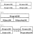
- the most common strategy is to locate the Rh and optionally the Pt component in the top or 2 nd WC layer with Pd preferably located in the bottom or 1 st WC layer (see e.g., US5593647 ).
- Separation of both the WC components and PGMs can also be achieved for single bricks by zoning whereby the front or rear zone or section of a WC layer can consist of different support components or different PGM components or more commonly different concentrations of a given PGM such as Pd.
- One advantage for separation of the PGMs in layers or zones is that more optimum supports and promoters for each PGM can be used so as to maximize overall performance.
- Rh is invariably located in the top (2 nd ) layer with optionally Pt also present while Pd is located in the 1 st or bottom layer (see e.g., US5593647 ).
- both the top (2 nd ) and bottom (1 st ) layers ideally contain a high surface area refraction oxide support such as a gamma or gamma/theta/delta alumina with further addition of promoters, stabilizers and a suitable oxygen storage component (OSC).
- OSC oxygen storage component
- the WC design is preferably free of an OSC and consists of a high surface area refractory oxide support such as a gamma or theta/delta alumina with appropriate stabilizers and additives.
- the rear catalyst, zone or UB catalyst have an OSC present in the bottom and top layers.
- the TWC catalysts according to the present invention comprise at least a front (upstream) brick or zone and a rear (downstream) brick or zone. Both the front and rear bricks or zones comprise at least two layers; however, in the rear brick or zone, the 1 st (lower) catalytic layer comprises less than 1% of an OSC.
- one or more bricks or zones may be placed between the front and rear bricks or zones.
- the zones or bricks are located in a single converter, butted together or separated by a defined space. In some embodiments, the bricks are located in separate converters.
- two or more separate converters are provided and at least one converter contains a rear zone or brick with at least two layers and the absence of OSC in the 1 st catalytic layer.
- the furthest downstream converter contains a rear zone or brick with at least two layers and the absence of OSC in the 1 st catalytic layer.
- the invention is directed to a catalyst composite for the purification of exhaust gases of a combustion engine substantially running under stoichiometric conditions comprising in sequence and in order:
- the front 2 nd catalytic layer and the rear 2 nd catalytic layer form one continuous layer.
- the continuous layer may have a gradient from the upstream end to the downstream end.
- the front 2 nd catalytic layer and the rear 2 nd catalytic layer may be made of the same materials in the same or different concentrations.
- a 1 st layer of the catalytic material is deposited on a substrate or a bottom layer already deposited on a substrate to form a lower coating.
- a 2 nd catalytic layer is deposited on and having physical contact with the 1 st layer to form the upper coating.
- the front (upstream) zone or brick that comes into contact with the exhaust first is closest to the engine and has a bottom (1 st ) catalytic layer and a top (2 nd ) catalytic layer.
- the rear (downstream) zone or brick is one that comes into contact with the exhaust after contact with a prior zone or brick.
- the rear zone or brick has a bottom (1 st ) catalytic layer and a top (2 nd ) catalytic layer.
- the front and rear zones or bricks can be in the same converter and can be touching each other or be separated by a distance, e.g. about an inch or so. Alternatively, the front and rear zones or bricks can be in separate converters which may be separated by a large distance, e.g. about 1 - 6 feet.
- the amount of OSC in the rear 1 st catalytic layer is preferably about 0.5%, more preferably about 0.25%, and most preferably about 0.1% by weight of OSC.
- an exhaust treatment system comprising the catalyst composite.
- the exhaust treatment system may further comprise one or more exhaust treatment devices selected from the group consisting of gasoline particulate filter traps (GPT), HC traps and NOx adsorber catalysts.
- GPT gasoline particulate filter traps
- the present invention provides methods for treating exhaust gases which comprises contacting a gaseous stream comprising hydrocarbons, carbon monoxide, and nitrogen oxides with a layered catalyst composite or an exhaust treatment system as described herein, wherein the catalytic material employed is effective to substantially simultaneously oxidize the carbon monoxide and the hydrocarbons and reduce the nitrogen oxides.
- the exhaust gas temperature at the catalyst inlet can vary from room temperature to as high as 1100°C, however typical catalyst operating temperatures by design fall in the range of about 300 - 900°C.
- the present invention is directed to a three-way conversion (TWC) catalyst and the compositions and locations of the catalytic layers relative to the direction of exhaust gas flow.
- the TWC catalysts according to the present invention comprise at least a front (upstream) brick or zone and a rear (downstream) brick or zone, wherein the rear brick or zone comprises at least two layers, wherein the 1 st (lower) catalytic layer comprises less than 1% of an OSC.
- TWC catalysts according to the present invention provide large performance benefits that are unexpected based on the teachings and best practices in the art prior to the instant invention.
- the present invention relates to a layered catalyst composite of the type generally referred to as a three-way conversion (TWC) catalyst having the capability to simultaneously catalyze the oxidation of hydrocarbons and carbon monoxide and the reduction of nitrogen oxides.
- the catalyst composite is divided into at least two sections either by using different zones on one substrate or using separate bricks being located in a single converter, butted together, or separated by a defined space as in separate converters.
- the platinum group metal (PGM) loading of the catalytic layers is about 0.001 - 20.0% by weight.
- each layer of the catalytic layers may comprise a different composition.
- each layer has a loading of from about 0.2 - 2.8 g/in 3 .
- each layer has a PGM loading of from about 0.01% by weight to about 20.0% by weight of the layer.
- each of the respective layers is deposited at a PGM loading of about 0.02 - 15.0% by weight.
- the catalyst composite refers to a PGM content of the layers which are as follows:
- the rear 2 nd catalytic layer always comprises rhodium as a PGM but may also comprise other PGMs as well. Rh is preferred in the rear 2 nd catalytic layer as NOx reduction based on the 2CO + 2NO ⁇ N 2 + 2CO 2 reaction is most efficient at intermediate temperatures in the range of 300 - 600°C.
- the amount of rhodium in a layer is about 0.01 - 1.0% by weight, preferably 0.02 - 0.5%, and most preferably 0.05 - 0.25% by weight.
- the front and rear 1 st catalytic layers always comprise palladium as a PGM but may also comprise other PGMs as well.
- the front and rear 1 st catalytic layers only comprise palladium as a PGM.
- Palladium is particularly effective for HC oxidation and is often concentrated in the front 1 st catalytic layer of the front brick so as to initiate HC light-off as soon as possible. This arises as the concentration of HC emitted from the engine is greater in the initial stages of vehicle operation in contrast to NOx which is emitted largely after warm-up of the vehicle.
- the amount of palladium in the front and rear 1 st catalytic layers is about 0.1 - 15.0% by weight, preferably about 0.2 - 10.0%, and most preferably about 0.5 - 5.0% by weight.
- Pt as a PGM present in the layers, especially the front and rear 2 nd catalytic layers.
- Pt has the advantage of being particularly effective for hard HC (saturated HCs) oxidation and may advantageously form alloys with Rh. Under normal stoichiometric/rich/lean exhaust gas conditions the surface of the alloy is rich in Rh which protects this PGM from negative interactions with the support.
- an amount of platinum group metal is up to about 4% by weight of the layer. In some embodiments, the amount of platinum in a layer is about 0.05 - 5% by weight, preferably about 0.1 - 2.0%, and most preferably about 0.3 - 1.0% by weight. In some embodiments, the platinum content of the layers is as follows:
- Reference to OSC oxygen storage component refers to an entity that has multi-valence state and can actively react with oxidants such as oxygen or nitrogen oxides under oxidative conditions, or reacts with reductants such as carbon monoxide (CO), hydrocarbons (HCs) or hydrogen under reduction conditions.
- Suitable oxygen storage components may include one or more oxides of one or more rare earth or transition metals selected from the group consisting of cerium, zirconium, terbium, iron, copper, manganese, cobalt, praseodymium, lanthanum, yttrium, samarium, gadolinium, dysprosium, ytterbium, niobium, neodymium, and mixtures of two or more thereof.
- suitable oxygen storage components include ceria, praseodymia, or combinations thereof.
- Delivery of an OSC to the layer can be achieved by the use of, for example, mixed oxides.
- ceria can be delivered by a mixed oxide of cerium and zirconium, and/or a mixed oxide of cerium, zirconium and neodymium with optionally other rare earths such as lanthanum or yttrium also present.
- praseodymia may be delivered by a mixed oxide of praseodymium and zirconium, and/or a mixed oxide of praseodymium, cerium, lanthanum, yttrium, zirconium, and neodymium.
- Suitable compositions can be found in US6387338 and US6585944 .
- the OSC can be present up to about 80% by weight of the layer, preferably about 20 - 70%, and most preferably about 30 - 60%.
- the ceria or praseodymia content in the range of about 3 - 98%, preferably about 10 - 60%, most preferably about 20 - 40% by weight of OSC.
- Suitable oxygen storage components may include one or more oxides of one or more rare earth or transition metals selected from the group consisting of cerium, zirconium, terbium, iron, copper, manganese, cobalt, praseodymium, lanthanum, yttrium, samarium, gadolinium, dysprosium, ytterbium, niobium, neodymium, and mixtures of two or more thereof.
- the catalyst composite according to the invention comprises a content of oxygen storage component (OSC) by weight of the layer as follows:
- the catalyst composite further comprises exhaust treatment materials selected from the group consisting of hydrocarbon storage components, NOx storage components as the current design may have particular applicability for exhaust treatment systems comprising HC traps and/or NOx adsorber functionalities.
- Current state-of-the-art catalyzed HC trap designs utilize an undercoat (UC - see later) consisting of HC trapping materials inclusive of various zeolites with a TWC overcoat (OC) of one or two layers as described in Japanese patents JP7124468 and JP7124467 and US7442346 .
- Optimum performance is achieved for designs whereby the rear 1 st layer does not contain OSC and where the rear 2 nd catalytic layer does contain an OSC as described in the current invention for optimum configuration of the WC composition in 1 st and 2 nd catalytic layers of the front and rear technology.
- the newest design for HC trap location is in the cooler rear or underbody (UB) location ( US7442346 ) as distinct from earlier strategies of placing the HC trap in the CC position ( US 5772972 ; Silver R. G., Dou D., Kirby C. W., Richmond R. P., Balland J., and Dunne S.; SAE 972843, and references therein) again in line with the current configuration of WC layers.
- a preferred location of the adsorber is again in the cooler UB location with an active TWC also present to both generate H 2 and to complete HC/CO combustion during the rich/lean transients.
- a suitable support according to some embodiments of the present invention is a refractory oxide support.
- Reference to a "support" in a catalyst layer refers to a material onto or into which platinum group metals, stabilizers, promoters, binders or other additives and the like are dispersed or impregnated, respectively.
- a support can be activated and/or stabilized as desired. Examples of supports include, but are not limited to, high surface area refractory metal oxides, composites containing oxygen storage components, and molecular sieves as is well known in the art.
- the support of each layer independently comprises a compound that is activated, stabilized, or both selected from the group consisting of, but not limited to, alumina, silica, silica-alumina, alumino-silicates, alumina-zirconia, lanthana-alumina, lanthana-zirconia-alumina, baria-alumina, baria lanthana-alumina, alumina-chromia, and alumina-ceria.
- the support may comprise any suitable material, for example, a metal oxide comprising gamma-alumina or promoter-stabilized gamma-alumina having a specific surface area of about 50 - 350 m 2 /g, preferably about 75 - 250 m 2 /g, and most preferably about 100 - 200 m 2 /g.
- the alumina present in any of the layers comprises, optionally zirconia- and lanthana-stabilized (gamma-) alumina in a loading of about 5 - 90% by weight of the layer, preferably about 20 - 70%, and most preferably about 30 - 60%.
- a suitable stabilized alumina may comprise about 0.1 - 15% by weight of lanthana (preferably as a stabilizer), preferably about 0.5 - 10%, and most preferably about 1 - 7%; and/or about 0.5 - 15%, preferably about 0.5 - 10%, and most preferably about 1 - 7% zirconia (preferably as a stabilizer in gamma-alumina).
- the alumina comprises gamma-alumina stabilized by barium oxide, neodymia, lanthana and combinations thereof.
- the stabilizer loading on a suitable alumina is about 0 - 4% by weight of support, preferably about 1 - 3%, and most preferably about 2% barium oxide.
- lanthana, zirconia and neodymia are stabilizers and that, in some embodiments, one or more can be at the same loading range, i.e. lanthana, zirconia, neodymia, or a combination thereof can be present at 0.1 - 15% by weight.
- a molecular sieve material can be selected from the group consisting of faujasite, chabazite, silicalite, zeolite X, zeolite Y, ultrastable zeolite Y, offretite, Beta, ferrierite and ZSM/MFI zeolites.
- ion-exchanged Beta zeolites may be used, such as Fe/Beta zeolite, or preferably, H/Beta zeolite.
- the zeolites preferably Beta zeolites may have a silica/alumina molar ratio of from at least about 25/1 or at least about 50/1, with useful ranges of from about 25/1 to 1000/1, 50/1 to 500/1 as well as about 25/1 to 300/1, for example.
- the layers provided are the 1 st front and/or 1 st rear catalytic layer comprising a stabilized alumina, such as gamma-alumina, which can be present in an amount in the range of about 10 - 90% by weight of the layer, preferably about 20 - 70%, and most preferably about 30 - 60%, substantially only palladium, which can be present in an amount in the range of about 0.1 - 10.0% by weight of the layer, preferably about 0.1 - 5.0%, and most preferably about 0.2 - 2.0%.
- a stabilized alumina such as gamma-alumina
- the front and rear 2 nd catalytic layers comprise a stabilized alumina, such as gamma-alumina, which can be present in an amount in the range of about 10 - 90% by weight of the layer, preferably about 20 - 70%, and most preferably about 30 - 60%; rhodium, which can be present in an amount in the range of about 0.01 - 1.0% by weight of the layer, preferably about 0.05 - 0.5%, and most preferably about 0.1 - 0.25%.
- a stabilized alumina such as gamma-alumina, which can be present in an amount in the range of about 10 - 90% by weight of the layer, preferably about 20 - 70%, and most preferably about 30 - 60%
- rhodium which can be present in an amount in the range of about 0.01 - 1.0% by weight of the layer, preferably about 0.05 - 0.5%, and most preferably about 0.1 - 0.25%.
- the front and rear 2 nd catalytic layers comprise a stabilized alumina, such as lanthana stabilized gamma-alumina, which can be present in an amount in the range of about 10 - 90% by weight of the layer, preferably about 20 - 70%, and most preferably about 30 - 60%, platinum, which can be present in an amount in the range of up to about 4.0% by weight of the layer, preferably about 0.05 - 2.0%, and most preferably about 0.1 - 1.0%, whereby rhodium, which can be present in an amount in the range of about 0.01 - 1.0% by weight of the layer, preferably about 0.05 - 0.5%, and most preferably about 0.1 - 0.25%.
- a stabilized alumina such as lanthana stabilized gamma-alumina
- a given layer further comprises up to about 40%, preferably about 5 - 30%, and most preferably about 10 - 20% of a stabilizer comprising one or more non-reducible metal oxides wherein the metal is selected from the group consisting of barium, calcium, magnesium, strontium, and mixtures thereof.
- a layer may further comprise, according to one embodiment, 0 to about 40%, preferably about 5 - 30%, and most preferably about 10 - 30% of one or more promoters comprising one or more rare earth or transition metals selected from the group consisting of lanthanum, praseodymium, yttrium, zirconium, samarium, gadolinium, dysprosium, ytterbium, niobium, neodymium, and mixtures thereof.
- a layer may further comprise, according to one embodiment, 0 to about 20%, preferably about 2 - 20%, and most preferably about 5 - 10% of one or more binders comprising one or more alumina boehmites, zirconia hydroxites or silica sols, and mixtures thereof.
- a layer may further comprise, according to one embodiment, 0 to about 20%, preferably about 0 - 12%, more preferably about 0 - 6% of one or more of further additives comprising hydrogen sulfide (H 2 S) control agents such as nickel, iron, zinc, boron, manganese, strontium and mixtures thereof.
- H 2 S hydrogen sulfide
- Segregated washcoats that address certain catalytic functionalities can be used.
- the use of at least two layers on a substrate can lead to more efficient use of and/or to a decrease in overall amount of, for example, platinum group metals due to their separation from one another.
- compositions of each layer are tailored to address a particular function of the TWC catalyst.
- overcoat layers that are substantially free of platinum group metals and that comprise alumina and one or more base metal oxides are, for example, effective to trap poisons such as sulfur, nitrogen, magnesium, calcium, zinc and phosphorous-containing components.
- base metal oxides include, but are not limited to SrO, La 2 0 3 , Nd 2 0 3 , or BaO.
- the catalyst composite in its zoned embodiment comprises a substrate comprising an inlet axial end, an outlet axial end, wall elements having a length extending between the inlet axial end to the outlet axial end and a plurality of axially enclosed channels defined by the wall elements; and a front part of the composite catalyst deposited on the wall elements adjacent the inlet axial end and having a length extending less than the wall length of the wall elements, wherein the inlet catalyst composite comprises the catalyst composite described above.
- This catalyst composite further comprises a rear part of the catalyst composite adjacent to the outlet axial end and having a length extending for less than the length of the wall elements.
- the front part of the catalyst composite may comprise (a) a substrate; (b) a 1 st catalytic layer deposited on the substrate, the 1 st catalytic layer comprising palladium deposited on a support; (c) a 2 nd catalytic layer deposited on the 1 st catalytic layer, the 2 nd catalytic layer comprising rhodium deposited on a support; and for example, the rear part of the catalyst composite may comprise (a) a substrate; (b) a 1 st catalytic layer deposited on the substrate, the 1 st catalytic layer comprising palladium deposited on a support; (c) a 2 nd catalytic layer deposited on the 1 st catalytic layer, the 2 nd catalytic layer comprising rhodium deposited on a support.
- the front part of the catalyst composite overlaps the rear part of the catalyst composite.
- the front part of the catalyst composite comprises between about 10 - 90%, more preferably about 20 - 60%, and most preferably about 25 - 50% of the total length (e.g., 1 - 15 cm of total length) of the substrate, such as a honeycomb substrate.
- the rear part of the catalyst composite comprises between about 10 - 90%, more preferably about 40 - 80%, and most preferably about 50 - 75% of the total length of the substrate, such as a honeycomb substrate.
- one or more catalyst composites of the invention are disposed on a substrate.
- the substrate may be any of those materials typically used for preparing catalysts, and will preferably comprise a ceramic or metal honeycomb structure.
- Any suitable substrate may be employed, such as a monolithic substrate of the type having fine, parallel gas flow passages extending there through from an inlet or an outlet face of the substrate, such that passages are open to fluid flow there through (referred to as honeycomb flow through substrates).
- honeycomb flow through substrates The passages, which are essentially straight paths from their fluid inlet to their fluid outlet, are defined by walls on which the catalytic material is coated as a washcoat so that the gases flowing through the passages contact the catalytic material.
- the flow passages of the monolithic substrate are thin-walled channels, which can be of any suitable cross-sectional shape and size such as trapezoidal, rectangular, square, sinusoidal, hexagonal, oval, circular, etc.
- Such structures may contain from about 60 - 900 or more gas inlet openings (i.e., cells) per square inch of cross section.
- the substrate can also be a wall-flow filter substrate, where the channels are alternately blocked, allowing a gaseous stream entering the channels from one direction (inlet direction), to flow through the channel walls and exit from the channels from the other direction (outlet direction).
- a dual oxidation catalyst composition can be coated on the wall-flow filter. If such a substrate is utilized, the resulting system will be able to remove particulate matter along with gaseous pollutants.
- the wall-flow filter substrate can be made from materials commonly known in the art, such as cordierite or silicon carbide.
- the catalyst composite of the present invention shows a front zone comprising the 1 st and 2 nd catalytic layers deposited on the inlet channels of a wall-flow filter, and the rear zone comprising the 1 st and 2 nd catalytic layers deposited on the outlet channels of a wall-flow filter.
- the front zone can be a wall-flow filter substrate and the rear zone can be a flow-through honeycomb substrate. In some embodiments, the front zone is a flow-through honeycomb substrate and the rear zone is coated on a wall-flow filter element.
- the ceramic substrate may be made of any suitable refractory material, e.g., cordierite, cordierite-alumina, silicon nitride, zircon mullite, spodumene, alumina-silica magnesia, zircon silicate, sillimanite, a magnesium silicate, zircon, petalite, alumina, an aluminosilicate and the like.
- suitable refractory material e.g., cordierite, cordierite-alumina, silicon nitride, zircon mullite, spodumene, alumina-silica magnesia, zircon silicate, sillimanite, a magnesium silicate, zircon, petalite, alumina, an aluminosilicate and the like.
- the substrates useful for the catalyst composite of the present invention may also be metallic in nature and be composed of one or more metals or metal alloys.
- the metallic substrates may be employed in various shapes such as corrugated sheet or monolithic form.
- Preferred metallic supports include the heat resistant metals and metal alloys such as titanium and stainless steel as well as other alloys in which iron is a substantial or major component.
- Such alloys may contain one or more of nickel, chromium, and/or aluminum, and the total amount of these metals may advantageously comprise at least about 15 wt % of the alloy, e.g., about 10 - 25 wt % of chromium, about 3 - 8 wt % of aluminum and up to about 20 wt % of nickel.
- the alloys may also contain small or trace amounts of one or more other metals such as manganese, copper, vanadium, titanium and the like.
- the surface of the metal substrates may be oxidized at high temperatures, e.g., about 1000°C and higher, to improve the resistance to corrosion of the alloys by forming an oxide layer on the surfaces of the substrates. Such high temperature-induced oxidation may enhance the adherence of the refractory metal oxide support and catalytically promoting metal components to the substrate.
- one or more catalyst compositions may be deposited on an open cell foam substrate. Such substrates are well known in the art, and are typically formed of refractory ceramic or metallic materials.
- the WC composition configuration of the present invention is not taught or recognized as having favorable performance or other beneficial features.
- the prior art specifically teaches against this configuration as outlined in detail in the Hu et al. patent and references therein.
- the layered catalyst composite of the present invention may be readily prepared by processes known in the art. See, for example, US6478874 and EP0441173 . A representative process is set forth below.
- washcoat has its usual meaning in the art of a thin, adherent coating of a catalytic or other material applied to a substrate material, such as a honeycomb-type substrate member, which is sufficiently porous to permit the passage there through of the gas stream being treated.
- the catalyst composite can be readily prepared in layers on a monolithic substrate.
- a first layer of a specific washcoat finely divided particles of a high surface area refractory metal oxide such as gamma-alumina are slurried in an appropriate solvent, e.g., water.
- the substrate may then be dipped one or more times in such slurry or the slurry may be coated on the substrate such that there will be deposited on the substrate the desired loading of the metal oxide, e.g., about 0.5 - 2.5 g/in 3 .
- the coated substrate is calcined by heating, e.g., at about 300 - 800°C for about 1 - 3 hours.
- the palladium component is utilized in the form of a compound or complex to achieve high dispersion of the component on the refractory metal oxide support, e.g., activated alumina.
- the term "palladium component” means any compound, complex, or the like which, upon calcination or use thereof, decomposes or otherwise converts to a catalytically active form, usually the metal or the metal oxide.
- Watersoluble compounds or water-dispersible compounds or complexes of the metal component may be used as long as the liquid medium used to impregnate or deposit the metal component onto the refractory metal oxide support particles does not adversely react with the metal or its compound or its complex or other components which may be present in the catalyst composite and is capable of being removed from the metal component by volatilization or decomposition upon heating and/or application of a vacuum.
- aqueous solutions of soluble compounds or complexes of the precious metals are utilized.
- suitable compounds are palladium nitrate or rhodium nitrate.
- the slurry is thereafter milled to result in substantially all of the solids having particle sizes of less than about 20 microns, i.e., between about 0.1 - 15 microns, in an average diameter.
- the combination may be accomplished in a ball mill or other similar equipment, and the solids content of the slurry may be, e.g., about 15 - 60 wt %, more particularly about 25 - 40 wt %.
- Additional layers may be prepared and deposited upon the first (1 st ) catalytic layer in the same manner as described above for deposition of the first (1 st ) catalytic layer upon the substrate.
- the first layer which is deposited upon, i.e., coated upon and adhered to, the substrate comprises palladium deposited on a support.
- a suitable support is a high surface area refractory metal oxide.
- the loading of the first layer upon the substrate is between about 0.2 - 2.8 g/in 3 .
- high surface area refractory metal oxides include, but are not limited to, alumina, silica, titania and zirconia and mixtures thereof.
- the refractory metal oxide may consist of or contain a mixed oxide such as silica-alumina, alumino-silicates which may be amorphous or crystalline, alumina-zirconia, alumina-lanthana, alumina-baria-lanthana-neodymia, alumina-chromia, alumina-baria, alumina-ceria, and the like.
- An exemplary refractory metal oxide comprises gamma-alumina having a specific surface area of about 50 - 350 m 2 /g and which is present in a loading of about 10 - 90% by weight of the washcoat.
- the first layer will have oxygen storage components in the range of about 10 - 80% by weight with ceria content ranging form about 3 - 98% by weight of the layer material.
- Examples of palladium loading in the first layer include up to about 15% by weight, alternatively, between about 0.05 and about 10% by weight, of palladium.
- This layer may also contain up to about 40% of stabilizers/promoters/binders/additives.
- Suitable stabilizers include one or more non-reducible metal oxides wherein the metal is selected from the group consisting of barium, calcium, magnesium, strontium, and mixtures thereof.
- the stabilizer comprises one or more oxides of barium and/or strontium.
- Suitable promoters include one or more non-reducible oxides, or rare earth and transition metals selected from the group consisting of lanthanum, neodymium, praseodymium, yttrium, zirconium, samarium, gadolinium, dysprosium, ytterbium, niobium, and mixtures thereof.
- a 2 nd catalytic layer which is deposited upon, i.e., coated upon and adhered to, the front 1 st catalytic layer, comprises rhodium or rhodium and platinum deposited on a high surface area refractory metal oxide and/or oxygen storage component which may be any of those mentioned above with respect to the 1 st catalytic layer.
- the 2 nd catalytic layer will be present in a loading of about 0.2 - 2.8 g/in 3 , alternatively, between about 1 - 1.6 g/in 3 and will have substantially an amount of oxygen storage component at a loading of about 20 - 80% by weight.
- Oxygen storage components can be ceria containing ceria/zirconia composite with ceria in the range of from about 3 - 90 as weight percent. Preferably, about 5 - 55% of ceria by weight is in the composite.
- the 2 nd catalytic layer also can comprise gamma-alumina or stabilized gamma-alumina having a specific surface area of about 50 - 350 m 2 /g and which is present in a loading of about 10 - 90% by weight.
- rhodium will be present in the 2 nd catalytic layer in a loading of about 0.01 - 1.0% by weight, alternatively about 0.05 - 0.5% by weight of rhodium, preferably about 0.1 - 0.25% by weight of rhodium.
- palladium will be present in the 2 nd catalytic layer in a loading of about 0.1 - 10% by weight, alternatively about 0.1 - 5.0% by weight of palladium, preferably about 0.2 - 2.0% by weight of palladium.
- platinum will be present in the 2 nd catalytic layer in a loading of about 0.01 - 2.0% by weight, alternatively about 0.05 - 1.0% by weight of platinum, preferably about 0.1 - 0.5% by weight of platinum.
- the 2 nd catalytic layer may also contain about 0 - 40% by weight of a promoter(s).
- Suitable promoters include one or more base metal oxides wherein the metal is selected from the group consisting of barium, calcium, magnesium, strontium, one or more rare earth and transition metals selected from the group consisting of zirconium, lanthanum, praseodymium, yttrium, samarium, gadolinium, dysprosium, ytterbium, niobium, neodynium, and mixtures thereof.
- the rear 1 st catalytic layer which is deposited upon, i.e., coated upon and adhered to, the substrate comprises palladium deposited on a support.
- a suitable support may be a high surface area refractory metal oxide.
- the loading of the first layer upon the substrate is between about 0.2 - 2.8 g/in 3 .
- high surface refractory metal oxides include, but are not limited to, a high surface area refractory metal oxide such as alumina, silica, titania and zirconia and mixtures thereof.
- the refractory metal oxide may consist of or comprise a mixed oxide such as silica-alumina, alumo-silicates which may be amorphous or crystalline, alumina-zirconia, alumina-lanthana, alumina-baria-lanthana-neodymia, alumina-chromia, alumina-baria, and the like.
- An exemplary refractory metal oxide comprises gamma-alumina having a specific surface area of about 50 - 350 m 2 /g and which is present in a loading of about 0.5 - 2.8 g/in 3 .
- the first layer which is applied in the rear zone comprises less than 1% of oxygen storage materials by weight of the layer.
- Examples of palladium loading in the first layer include up to about 15% by weight, alternatively, between about 0.05 - 10% by weight of palladium, This layer may also contain up to about 40% by weight of stabilizers/promoters/binders/additives.
- Suitable stabilizers include one or more non-reducible metal oxides wherein the metal is selected from the group consisting of barium, calcium, magnesium, strontium, and mixtures thereof. In some embodiments, the stabilizer comprises one or more oxides of barium and/or strontium.
- Suitable promoters include one or more non-reducible oxides, or rare earth and transition metals selected from the group consisting of lanthanum, neodymium, praseodymium, yttrium, zirconium, samarium, gadolinium, dysprosium, ytterbium, niobium, and mixtures thereof.
- washcoats and coating has previously been described in US7041622 , Column 9, Lines 20 - 40; Column 10, lines 1 - 15, which is herein incorporated by reference in its entirety.
- Alumina stabilized with 4% by weight of lanthanum oxide, barium sulfate and a mixed oxide oxygen storage material with a composition of 42% ZrO 2 +HfO 2 , 43% CeO 2 , 5% Pr 6 O 11 and 10% La 2 O 3 by weight were used in the preparation of the slurry.
- a slurry was prepared by first adding nitric acid to water at 1 wt % based on the total solids in the slurry. BaSO 4 was then added with stirring followed by the OSC.
- the slurry was stirred for 15 minutes and then the alumina was added slowly and stirred for 30 minutes.
- the slurry was then milled (using a Sweco type mill) such that the d 50 was 4.5 - 5.5 microns; the d 90 was 17 - 21 microns, and 100% pass was less than 65 microns (i.e., 100% of the particles had a size less than 65 micrometers).
- the slurry was then weighed and the LOI (loss on ignition) was measured at 540°C to determine the total calcined solids content. Based on this value the weight of Pd solution need was calculated.
- Pd nitrate solution was then added to the slurry dropwise while stirring.
- the slurry specific gravity was in the range of 1.49 to 1.52
- parts were coated by dipping one end of a honeycomb ceramic monolith into the washcoat slurry, followed by drawing the slurry up into the channels using a vacuum. The part was then removed from the slurry and the channels cleared by applying a vacuum to the other end of the part.
- Washcoat loading was controlled by varying specific gravity, and other coating parameters such as vacuum time and the amount of slurry drawn into the honeycomb channels. After applying the washcoat, the parts were calcined at 540°C for 2 hours. After calcination the composition of the 1 st catalytic layer was as follows:
- the 2 nd catalytic layer of the conventional reference catalyst consisted of alumina stabilized with 4% by weight of lanthanum oxide, barium sulfate and a mixed oxide oxygen storage material with a composition of 58% ZrO 2 +HfO 2 , 32% CeO 2 , 8% Y 2 O 3 and 2% La 2 O 3 .
- the slurry was prepared as described above for the front 1 st catalytic layer. Rh was added drop-wise to the slurry over a period of 30 minutes while stirring. After coating and calcination at 540°C for 2 hours the composition of the front 2 nd catalytic layer of the catalyst was as follows:
- composition and manufacture of the rear 2 nd catalytic layer was identical with the conventional reference catalyst.
- the rear 1 st catalytic layer consisted of alumina stabilized with 4% by weight of lanthanum oxide and barium sulfate.
- the slurry was prepared as described above for the front 1 st catalytic layer. After calcination at 540°C for 2 hours the composition of the rear 1 st catalytic layer was as follows:
- the same oxygen storage material was used in the Rh layer of both the reference conventional uniform design and the zoned design according to the invention where the rear 1 st catalytic layer of the rear zone or brick does not contain an oxygen storage material.
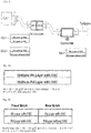
- the reference catalyst in the current case consisted of a 6" long monolith while the test system consisted of a 3" front brick of identical WC design and composition.
- the 3" rear brick was identical to the front catalyst except the OSC was removed from the rear 1 st catalytic layer and some extra alumina/promoter was added in its place to give a total WC load for the 1 st layer of 1.8 g/in 3 . Both front and rear 3" bricks were butted together in the converter to represent a zoned configuration.
- Aging consisted of 50 or 100 hours of a 4-mode thermal aging protocol.
- the cycle consisted of four modes within a period of 60 seconds.
- the first mode consisted of a stoichiometric cruise, followed by a rich condition, a rich condition with secondary air injection and finally a stoichiometric condition with secondary air injection.
- Mode 1 lasted for 40 seconds with a catalyst inlet bed T (thermocouple placed 1" from the catalyst inlet face) of 904 ⁇ 2°C.
- Mode 2 lasted for 6 seconds with a catalyst inlet CO concentration at 4.0 ⁇ 0.1%.
- Mode 3 lasted for 10 seconds with a catalyst inlet bed T of 980°C ⁇ 2°C; the engine out CO concentration was 4.0 ⁇ 0.1 vol% and a secondary air injection at the catalyst inlet was used to give an O 2 concentration of 2.5 ⁇ 0.1 vol%.
- Mode 4 lasted for 4 seconds with an engine out stoichiometric exhaust gas composition and secondary air injection to give an O 2 concentration of 4.5 ⁇ 0.1 vol% at the catalyst inlet.
- the engine used for the aging was a 7.4L V-8 equipped with sequential multi-port fuel injection.
Landscapes
- Chemical & Material Sciences (AREA)
- Engineering & Computer Science (AREA)
- Chemical Kinetics & Catalysis (AREA)
- Materials Engineering (AREA)
- Organic Chemistry (AREA)
- Combustion & Propulsion (AREA)
- Health & Medical Sciences (AREA)
- Environmental & Geological Engineering (AREA)
- Biomedical Technology (AREA)
- Analytical Chemistry (AREA)
- General Chemical & Material Sciences (AREA)
- Oil, Petroleum & Natural Gas (AREA)
- Toxicology (AREA)
- Mechanical Engineering (AREA)
- General Engineering & Computer Science (AREA)
- Catalysts (AREA)
- Exhaust Gas After Treatment (AREA)
- Processes For Solid Components From Exhaust (AREA)
- Exhaust Gas Treatment By Means Of Catalyst (AREA)
Claims (14)
- Katalysator-Verbundstoff zur Reinigung von Abgasen eines Verbrennungsmotors, der im Wesentlichen unter stöchiometrischen Bedingungen läuft, nacheinander in folgender Reihenfolge Folgendes umfassend:eine vordere Doppelschicht auf einem Substrat, die eine 1. (untere) katalytische Schicht und eine 2. (obere) katalytische Schicht aufweist; undeine hintere Doppelschicht auf einem Substrat, die eine hintere 1. (untere) katalytische Schicht und eine hintere 2. (obere) katalytische Schicht aufweist;wobei die vordere 2. katalytische Schicht und die hintere 2. katalytische Schicht Rhodium als Platingruppenmetallverbindung umfassen;wobei die vordere 1. katalytische Schicht und die hintere 1. katalytische Schicht Palladium als Platingruppenmetallverbindung umfassen;wobei die hintere 1. katalytische Schicht zu weniger als 1 Gew.-% der Schicht ein Material eines Sauerstoffspeicherbestandteils (OSC) umfasst; undwobei die vordere Doppelschicht eine vordere Zone bildet und die hintere Doppelschicht eine hintere Zone bildet, wobei der Katalysator-Verbundstoff ein Einzelbausteinsystem ist oder die vordere Doppelschicht in einem vorderen Baustein angeordnet ist und die hintere Doppelschicht in einem hinteren Baustein angeordnet ist, wobei der Katalysator-Verbundstoff ein Mehrbausteinsystem ist, wobei der Gehalt an Sauerstoffspeicherbestandteil (OSC) bezogen auf das Gewicht der Schichten wie folgt ist:vordere 1. katalytische Schicht - 10-80 Gew.-% der Schicht;vordere 2. katalytische Schicht - 20-80 Gew.-% der Schicht; undhintere 2. katalytische Schicht - 20-80 Gew.-% der Schicht.
- Katalysator-Verbundstoff gemäß Anspruch 1, wobei die vordere 2. katalytische Schicht und die hintere 2. katalytische Schicht eine kontinuierliche Schicht bilden.
- Katalysator-Verbundstoff gemäß Anspruch 1, wobei der PGM-Gehalt der Schichten wie folgt ist:vordere 1. katalytische Schicht- 0,1-12,0 Gew.-% der Schicht;hintere 1. katalytische Schicht - 0,01-6,0 Gew.-% der Schicht;vordere 2. katalytische Schicht - 0,01-2 Gew.-% der Schicht;hintere 2. katalytische Schicht - 0,01-2 Gew.-% der Schicht.
- Katalysator-Verbundstoff gemäß Anspruch 1, wobei die vordere 2. und/oder hintere 2. katalytische Schicht Platin umfasst.
- Katalysator-Verbundstoff gemäß Anspruch 4, wobei der Platingehalt der Schichten wie folgt ist:vordere 2. katalytische Schicht - 0,01-12,0 Gew.-% der Schicht; undhintere 2. katalytische Schicht - 0,01-5,0 Gew.-% der Schicht.
- Katalysator-Verbundstoff gemäß Anspruch 1, ferner umfassend Abgasbehandlungsmaterialien, ausgewählt aus der Gruppe bestehend aus Kohlenwasserstoffspeicher- (HC-) und NOx-Speicherkatalysatoren, wobei die HC-Speicher- und NOx-Speicherschicht als Grundierungs-WC-Schicht auf dem Substrat angeordnet sind, um die vordere Zone oder den vorderen Baustein und/oder die hintere Zone oder den hinteren Baustein zu bilden.
- Katalysator-Verbundstoff gemäß Anspruch 1, ferner umfassend Abgasbehandlungsmaterialien, ausgewählt aus der Gruppe bestehend aus Kohlenwasserstoffspeicher- (HC-) und NOx-Speicherkatalysatoren, wodurch die HC-Speicher- und NOx-Speicherschicht als obere oder Mantel-WC-Schicht angeordnet sind, um die vordere Zone oder den vorderen Baustein und/oder die hintere Zone oder den hinteren Baustein zu bilden.
- Katalysator-Verbundstoff gemäß Anspruch 1, wobei der Katalysator-Verbundstoff mindestens teilweise auf einer Grundierungsschicht (UC) angelagert ist, die Material umfasst, das ausgewählt ist aus der Gruppe bestehend aus HC-Speichermaterial oder NOx-Speichermaterial.
- Katalysator-Verbundstoff gemäß Anspruch 1, wobei der Katalysator-Verbundstoff ein Einlass-Axialende, ein Auslass-Axialende, Wandelemente aufweisend eine Länge, die sich zwischen dem Einlass-Axialende zum Auslass-Axialende erstreckt und eine Vielzahl von axial umschlossenen Kanälen, die von den Wandelementen definiert werden, umfasst; wobei die vordere 1. und 2. katalytische Schicht an den Wandelementen angrenzend an das Einlass-Axialende und aufweisend eine Länge, die sich weniger als die Wandlänge der Wandelemente erstreckt, angelagert sind, um die vordere Zone zu bilden; und
die hintere 1. und 2. katalytische Schicht an den Wandelementen angrenzend an das Auslass-Axialende und aufweisend eine Länge, die sich weniger als die Länge der Wandelemente erstreckt, angelagert sind, um die hintere Zone zu bilden. - Katalysator-Verbundstoff gemäß Anspruch 1, wobei die vordere 1. und 2. katalytische Schicht an den Einlasskanälen eines Wandstromfilters angelagert sind, um die vordere Zone zu bilden, und die hintere 1. und 2. katalytische Schicht an den Auslasskanälen des Wandstromfilters angelagert sind, um die hintere Zone zu bilden.
- Katalysator-Verbundstoff gemäß Anspruch 1, wobei die vordere 1. und 2. katalytische Schicht an den Kanälen eines Durchflusswabensubstrats angelagert sind, um die vordere Zone zu bilden, und die hintere 1. und 2. katalytische Schicht an den Einlass- und/oder Auslasskanälen eines Wandstromfilters angelagert sind, um die hintere Zone zu bilden.
- Abgasbehandlungssystem zur Reinigung von Abgasen eines Verbrennungsmotors, der im Wesentlichen unter stöchiometrischen Bedingungen läuft, umfassend den Katalysator-Verbundstoff gemäß Anspruch 1.
- Abgasbehandlungssystem gemäß Anspruch 12, ferner umfassend ein oder mehrere Abgasbehandlungsvorrichtungen, ausgewählt aus der Gruppe bestehend aus HC-Sperr- und NOx-Speicherkatalysator.
- Verfahren zum Behandeln der Abgase eines Verbrennungsmotors, der im Wesentlichen unter stöchiometrischen Bedingungen läuft, wobei das Verfahren Folgendes umfasst:Inkontaktbringen eines gasförmigen Stroms, der Kohlenwasserstoffe, Kohlenmonoxid und Stickoxide umfasst, mit einem Katalysator-Verbundstoff gemäß Anspruch 1, wobei der Katalysator-Verbundstoff dazu dient, um im Wesentlichen gleichzeitig das Kohlenmonoxid und die Kohlenwasserstoffe zu oxidieren und die Stickoxide zu reduzieren.
Applications Claiming Priority (2)
| Application Number | Priority Date | Filing Date | Title |
|---|---|---|---|
| US12/951,311 US8323599B2 (en) | 2010-11-22 | 2010-11-22 | Three-way catalyst having an upstream multi-layer catalyst |
| PCT/EP2011/070541 WO2012069405A1 (en) | 2010-11-22 | 2011-11-21 | Three-way catalytic system having an upstream multi - layer catalyst |
Publications (2)
| Publication Number | Publication Date |
|---|---|
| EP2643078A1 EP2643078A1 (de) | 2013-10-02 |
| EP2643078B1 true EP2643078B1 (de) | 2017-06-21 |
Family
ID=45093726
Family Applications (1)
| Application Number | Title | Priority Date | Filing Date |
|---|---|---|---|
| EP11790925.9A Active EP2643078B1 (de) | 2010-11-22 | 2011-11-21 | Dreiwegekatalysatorsystem mit einem anströmseitigen mehrschichtkatalysator |
Country Status (8)
| Country | Link |
|---|---|
| US (2) | US8323599B2 (de) |
| EP (1) | EP2643078B1 (de) |
| JP (1) | JP5841161B2 (de) |
| KR (1) | KR101913664B1 (de) |
| CN (1) | CN103201018B (de) |
| BR (1) | BR112013011920B1 (de) |
| RU (1) | RU2013128390A (de) |
| WO (1) | WO2012069405A1 (de) |
Cited By (2)
| Publication number | Priority date | Publication date | Assignee | Title |
|---|---|---|---|---|
| WO2020021511A1 (en) * | 2018-07-27 | 2020-01-30 | Johnson Matthey Public Limited Company | Improved twc catalysts containing high dopant support |
| RU2789587C2 (ru) * | 2018-07-27 | 2023-02-06 | Джонсон Мэттей Паблик Лимитед Компани | Улучшенные катализаторы twc, содержащие высокоэффективную подложку с допирующей добавкой |
Families Citing this family (89)
| Publication number | Priority date | Publication date | Assignee | Title |
|---|---|---|---|---|
| US8323599B2 (en) | 2010-11-22 | 2012-12-04 | Umicore Ag & Co. Kg | Three-way catalyst having an upstream multi-layer catalyst |
| JP5376261B2 (ja) * | 2011-03-10 | 2013-12-25 | トヨタ自動車株式会社 | 排ガス浄化用触媒 |
| EP3178552A1 (de) * | 2011-03-24 | 2017-06-14 | Umicore Shokubai Japan Co., Ltd. | Oxidationskatalysator zur abgasreinigung, verfahren zur herstellung davon und abgasreinigungsverfahren damit |
| MX2014001678A (es) * | 2011-08-10 | 2015-01-26 | Clean Diesel Tech Inc | Catalizador de solucion de paladio solido y metodos de elaboracion. |
| JP5938819B2 (ja) | 2011-10-06 | 2016-06-22 | ジョンソン、マッセイ、パブリック、リミテッド、カンパニーJohnson Matthey Public Limited Company | 排気ガス処理用酸化触媒 |
| GB201200784D0 (en) | 2011-12-12 | 2012-02-29 | Johnson Matthey Plc | Exhaust system for a lean-burn internal combustion engine including SCR catalyst |
| GB201200781D0 (en) | 2011-12-12 | 2012-02-29 | Johnson Matthey Plc | Exhaust system for a lean-burn ic engine comprising a pgm component and a scr catalyst |
| GB2497597A (en) | 2011-12-12 | 2013-06-19 | Johnson Matthey Plc | A Catalysed Substrate Monolith with Two Wash-Coats |
| GB201200783D0 (en) | 2011-12-12 | 2012-02-29 | Johnson Matthey Plc | Substrate monolith comprising SCR catalyst |
| CN104039425B (zh) * | 2011-12-22 | 2016-08-24 | 庄信万丰股份有限公司 | 改进的NOx捕集阱 |
| JP5807782B2 (ja) * | 2011-12-28 | 2015-11-10 | トヨタ自動車株式会社 | 排ガス浄化用触媒 |
| EP2650042B2 (de) | 2012-04-13 | 2020-09-02 | Umicore AG & Co. KG | Schadstoffminderungssystem für Benzinfahrzeuge |
| GB201207313D0 (en) * | 2012-04-24 | 2012-06-13 | Johnson Matthey Plc | Filter substrate comprising three-way catalyst |
| GB2513364B (en) | 2013-04-24 | 2019-06-19 | Johnson Matthey Plc | Positive ignition engine and exhaust system comprising catalysed zone-coated filter substrate |
| EP2858751B1 (de) * | 2012-06-06 | 2020-02-19 | Umicore Ag & Co. Kg | Startkatalysator zur vorgelagerten verwendung eines benzinpartikelfilters |
| US9522360B2 (en) * | 2012-06-06 | 2016-12-20 | Umicore Ag & Co. Kg | Three-way-catalyst system |
| US9512793B2 (en) * | 2012-10-16 | 2016-12-06 | GM Global Technology Operations LLC | Combustion driven ammonia generation strategies for passive ammonia SCR system |
| WO2014119749A1 (ja) * | 2013-01-31 | 2014-08-07 | ユミコア日本触媒株式会社 | 排ガス浄化用触媒及び該触媒を用いた排ガス浄化方法 |
| US9511350B2 (en) | 2013-05-10 | 2016-12-06 | Clean Diesel Technologies, Inc. (Cdti) | ZPGM Diesel Oxidation Catalysts and methods of making and using same |
| US9511355B2 (en) | 2013-11-26 | 2016-12-06 | Clean Diesel Technologies, Inc. (Cdti) | System and methods for using synergized PGM as a three-way catalyst |
| US20140274662A1 (en) | 2013-03-15 | 2014-09-18 | Cdti | Systems and Methods for Variations of ZPGM Oxidation Catalysts Compositions |
| GB2512648B (en) | 2013-04-05 | 2018-06-20 | Johnson Matthey Plc | Filter substrate comprising three-way catalyst |
| US20140357479A1 (en) * | 2013-05-29 | 2014-12-04 | Cdti | Variations for Synthesizing Zero Platinum Group Metal Catalyst Systems |
| DE102013210270A1 (de) | 2013-06-03 | 2014-12-04 | Umicore Ag & Co. Kg | Dreiwegkatalysator |
| US9545626B2 (en) | 2013-07-12 | 2017-01-17 | Clean Diesel Technologies, Inc. | Optimization of Zero-PGM washcoat and overcoat loadings on metallic substrate |
| GB201315892D0 (en) | 2013-07-31 | 2013-10-23 | Johnson Matthey Plc | Zoned diesel oxidation catalyst |
| KR102271951B1 (ko) * | 2013-10-03 | 2021-07-02 | 우미코레 아게 운트 코 카게 | 배기 후처리 시스템 |
| US20150148224A1 (en) * | 2013-11-26 | 2015-05-28 | Clean Diesel Technologies Inc. (CDTI) | Oxygen Storage Capacity and Thermal Stability of Synergized PGM Catalyst Systems |
| US9511358B2 (en) | 2013-11-26 | 2016-12-06 | Clean Diesel Technologies, Inc. | Spinel compositions and applications thereof |
| US9694348B2 (en) * | 2013-12-13 | 2017-07-04 | Cataler Corporation | Exhaust cleaning catalyst |
| JP6611611B2 (ja) * | 2013-12-13 | 2019-11-27 | 株式会社キャタラー | 排ガス浄化用触媒 |
| JP6632988B2 (ja) * | 2014-03-12 | 2020-01-22 | ビーエーエスエフ ソシエタス・ヨーロピアBasf Se | 改良された触媒化スートフィルター |
| DE102014204682A1 (de) | 2014-03-13 | 2015-10-01 | Umicore Ag & Co. Kg | Katalysatorsystem zur Reduzierung von Schadgasen aus Benzinverbrennungsmotoren |
| EP3151949A1 (de) * | 2014-06-06 | 2017-04-12 | Clean Diesel Technologies, Inc. | Rhodium-eisen-katalysatoren |
| US9764286B2 (en) | 2014-12-03 | 2017-09-19 | Ford Global Technologies, Llc | Zoned catalyst system for reducing N2O emissions |
| DE102016102027A1 (de) * | 2015-02-05 | 2016-08-11 | Johnson Matthey Public Limited Company | Drei-Wege-Katalysator |
| WO2016127012A1 (en) * | 2015-02-06 | 2016-08-11 | Johnson Matthey Public Limited Company | Three-way catalyst and its use in exhaust systems |
| JP6472677B2 (ja) | 2015-02-17 | 2019-02-20 | 株式会社キャタラー | 排ガス浄化用触媒 |
| EP3254759B1 (de) * | 2015-02-17 | 2019-04-03 | Cataler Corporation | Abgasreinigungskatalysator |
| JP6699113B2 (ja) * | 2015-08-28 | 2020-05-27 | 三菱自動車工業株式会社 | 内燃機関の排ガス浄化システム及び排ガス浄化触媒 |
| GB2546164A (en) | 2015-09-30 | 2017-07-12 | Johnson Matthey Plc | Gasoline particulate filter |
| DE102017100518A1 (de) | 2016-02-04 | 2017-08-10 | Umicore Ag & Co. Kg | System und Verfahren zur Abgasreinigung unter Vermeidung von Lachgas |
| EP3427824A4 (de) * | 2016-03-18 | 2019-02-27 | Cataler Corporation | Katalysator zur abgasreinigung |
| US10737219B2 (en) | 2016-03-22 | 2020-08-11 | Cataler Corporation | Exhaust gas purifying catalyst |
| US9919294B2 (en) * | 2016-04-27 | 2018-03-20 | Ford Global Technologies, Llc | Phosphorus tolerant catalyst washcoat structure |
| JP6724532B2 (ja) * | 2016-05-02 | 2020-07-15 | 三菱自動車工業株式会社 | 排ガス浄化触媒の製造方法及び排ガス浄化触媒 |
| JP6724531B2 (ja) * | 2016-05-02 | 2020-07-15 | 三菱自動車工業株式会社 | 内燃機関の排ガス浄化触媒 |
| EP3466541B1 (de) * | 2016-05-24 | 2020-09-16 | Cataler Corporation | Abgasreinigungskatalysator |
| JP7043398B2 (ja) * | 2016-06-07 | 2022-03-29 | 株式会社キャタラー | 排ガス浄化用触媒 |
| JP6533873B2 (ja) * | 2016-07-20 | 2019-06-19 | ユミコア日本触媒株式会社 | 内燃機関の排気ガスの浄化用触媒および該触媒を用いた排気ガスの浄化方法 |
| WO2018159556A1 (ja) * | 2017-02-28 | 2018-09-07 | 新日鉄住金マテリアルズ株式会社 | 触媒担持用ハニカム基材、排ガス浄化用触媒コンバータ |
| CN110709591A (zh) * | 2017-04-04 | 2020-01-17 | 巴斯夫公司 | 用于催化性污染治理的氢气还原剂 |
| WO2019043557A1 (en) * | 2017-08-28 | 2019-03-07 | Basf Corporation | THREE-WAY PHOSPHORUS-RESISTANT CATALYST |
| US11439987B2 (en) * | 2017-12-08 | 2022-09-13 | Johonson Matthey (Shanghai) Chemicals Co., Ltd | Multi-region TWC for treatment of exhaust gas from gasoline engine |
| JP7026530B2 (ja) * | 2018-02-22 | 2022-02-28 | エヌ・イーケムキャット株式会社 | 排ガス浄化用三元触媒 |
| US10781735B2 (en) | 2018-05-18 | 2020-09-22 | Umicore Ag & Co Kg | Exhaust emission reduction system having an HC-trap and NOx-trap combination designed for operating under strategic lean conditions |
| US11123720B2 (en) * | 2018-05-18 | 2021-09-21 | Umicore Ag & Co. Kg | Hydrocarbon trap catalyst |
| EP3806985A1 (de) * | 2018-06-12 | 2021-04-21 | BASF Corporation | Twc-system zur nox-steuerung bei brennstoffreduktion |
| JP7142705B2 (ja) * | 2018-08-22 | 2022-09-27 | 三井金属鉱業株式会社 | 排ガス浄化用触媒 |
| US11073061B2 (en) * | 2018-09-26 | 2021-07-27 | Ford Global Technologies, Llc | Multicomponent exhaust treatment system including an oxygen storage catalyst |
| CN109261220A (zh) * | 2018-09-28 | 2019-01-25 | 昆明贵研催化剂有限责任公司 | 一种非均匀涂覆尾气净化催化剂的制备方法及应用 |
| WO2020128786A1 (en) * | 2018-12-19 | 2020-06-25 | Basf Corporation | Layered catalyst composition and catalytic article and methods of manufacturing and using the same |
| US20220062869A1 (en) * | 2018-12-28 | 2022-03-03 | Umicore Shokubai Japan Co., Ltd. | Catalyst for exhaust gas purification, method for producing same, and exhaust gas purification method using same |
| DE102019100097B4 (de) | 2019-01-04 | 2021-12-16 | Umicore Ag & Co. Kg | Verfahren zur Herstellung von katalytisch aktiven Wandflussfiltern |
| DE102019100107A1 (de) | 2019-01-04 | 2020-07-09 | Umicore Ag & Co. Kg | Katalytisch aktives Filtersubstrat und Verfahren zur Herstellung sowie deren Verwendung |
| DE102019100099B4 (de) | 2019-01-04 | 2022-09-08 | Umicore Ag & Co. Kg | Verfahren zur Herstellung von katalytisch aktiven Wandflussfiltern, katalytisch aktiver Wandflussfilter und dessen Verwendung |
| EP3915680A4 (de) * | 2019-01-22 | 2022-03-09 | Mitsui Mining & Smelting Co., Ltd. | Katalysator zur reinigung von abgas |
| EP3942162A4 (de) * | 2019-03-18 | 2022-12-28 | BASF Corporation | Geschichteter tri-metallischer katalytischer artikel und verfahren zur herstellung des katalytischen artikels |
| JP7195995B2 (ja) | 2019-03-27 | 2022-12-26 | 株式会社キャタラー | 排ガス浄化用触媒 |
| KR102211944B1 (ko) * | 2019-04-04 | 2021-02-03 | 희성촉매 주식회사 | 귀금속 박층을 최상층으로 포함하는 다층구조의 배기가스 정화용 촉매 및 이의 제조방법 |
| CN109985624A (zh) * | 2019-04-29 | 2019-07-09 | 无锡威孚环保催化剂有限公司 | 三次涂覆的摩托车催化剂及其制备方法 |
| US11015503B2 (en) | 2019-05-29 | 2021-05-25 | Faurecia Emissions Control Technologies, Usa, Llc | Exhaust component assembly with heating element and carved substrate |
| CN113905819B (zh) * | 2019-05-31 | 2025-06-06 | 三井金属矿业株式会社 | 废气净化用催化剂和使用该废气净化用催化剂的废气净化系统 |
| JP7386651B2 (ja) * | 2019-09-02 | 2023-11-27 | 株式会社キャタラー | 排ガス浄化用触媒 |
| CN110801833B (zh) * | 2019-10-24 | 2022-11-11 | 浙江达峰汽车技术有限公司 | 一种汽车尾气净化催化剂定域化涂层及其制备方法 |
| KR20220102619A (ko) * | 2019-11-22 | 2022-07-20 | 바스프 코포레이션 | 농축된 pgm 영역을 갖는 배출 제어 촉매 물품 |
| EP3889404A1 (de) * | 2020-03-30 | 2021-10-06 | Johnson Matthey Public Limited Company | Mehrbereichs-twc-katalysatoren für die abgasbehandlung von benzinmotoren mit verbesserter h2s-dämpfung |
| US20230330638A1 (en) * | 2020-09-11 | 2023-10-19 | Basf Corporation | Layered catalytic article and process for preparing the catalytic article |
| JP2023547301A (ja) * | 2020-10-30 | 2023-11-10 | ジョンソン、マッセイ、パブリック、リミテッド、カンパニー | ガソリンエンジン排気ガス処理のための新規トリメタル白金族金属(pgm、platinum group metal)触媒 |
| JP7061655B1 (ja) * | 2020-11-06 | 2022-04-28 | 株式会社キャタラー | 排ガス浄化触媒装置 |
| EP4243965A4 (de) * | 2020-11-13 | 2024-10-09 | BASF Mobile Emissions Catalysts LLC | In zonen unterteilter katalytischer artikel |
| DE102021102926A1 (de) | 2021-02-09 | 2022-08-11 | Volkswagen Aktiengesellschaft | Katalysatorsystem mit radial inhomogener Sauerstoffspeicherkapazität |
| DE102021107129A1 (de) | 2021-03-23 | 2022-09-29 | Umicore Ag & Co. Kg | Partikelfilter für Benzinmotorenabgas |
| DE102021112955A1 (de) | 2021-05-19 | 2022-11-24 | Umicore Ag & Co. Kg | Beschichtungsprozess für einen Wandflussfilter |
| CN113304745B (zh) * | 2021-06-04 | 2022-08-12 | 中自环保科技股份有限公司 | 一种Pt-Pd-Rh三元催化剂及其制备方法 |
| CN117651608A (zh) | 2021-08-13 | 2024-03-05 | 庄信万丰股份有限公司 | 用于三效催化应用的含硫有机化合物辅助的金属纳米粒子合成 |
| JP2024067951A (ja) * | 2022-11-07 | 2024-05-17 | トヨタ自動車株式会社 | 排ガス浄化装置 |
| DE202023103234U1 (de) | 2023-06-13 | 2023-06-26 | Umicore Ag & Co. Kg | Beschichtungsvorrichtung |
| WO2025217014A1 (en) * | 2024-04-09 | 2025-10-16 | Basf Mobile Emissions Catalysts Llc | Low ammonia-emmiting mobile exhaust aftertreatment system |
Family Cites Families (33)
| Publication number | Priority date | Publication date | Assignee | Title |
|---|---|---|---|---|
| JPH03202154A (ja) * | 1989-12-27 | 1991-09-03 | Mazda Motor Corp | エンジンの排気ガス浄化用触媒 |
| DE4003939A1 (de) | 1990-02-09 | 1991-08-14 | Degussa | Katalysator fuer die reinigung der abgase von brennkraftmaschinen |
| EP0662862B1 (de) | 1992-09-28 | 1998-05-13 | ASEC Manufacturing Company | Palladium enthaltender dreiwegekatalysator für kraftwagen mit einem einzelnen träger |
| JP2682404B2 (ja) | 1993-11-01 | 1997-11-26 | 日産自動車株式会社 | 炭化水素吸着材および触媒の製造方法 |
| JPH07124468A (ja) | 1993-11-01 | 1995-05-16 | Nissan Motor Co Ltd | 炭化水素吸着材および吸着触媒の製造方法 |
| JP3052710B2 (ja) | 1993-12-20 | 2000-06-19 | 日産自動車株式会社 | 排ガス浄化装置 |
| WO1995035152A1 (en) | 1994-06-17 | 1995-12-28 | Engelhard Corporation | Layered catalyst composite |
| US6497851B1 (en) | 1994-12-06 | 2002-12-24 | Englehard Corporation | Engine exhaust treatment apparatus and method of use |
| US5772972A (en) | 1995-01-09 | 1998-06-30 | Ford Global Technologies, Inc. | Catalyst/hydrocarbon trap hybrid system |
| US5593647A (en) | 1995-03-31 | 1997-01-14 | General Motors Corporation | Catalytic converter having tri precious metal catalysts |
| US6087298A (en) | 1996-05-14 | 2000-07-11 | Engelhard Corporation | Exhaust gas treatment system |
| US5981427A (en) | 1996-09-04 | 1999-11-09 | Engelhard Corporation | Catalyst composition |
| US6478874B1 (en) | 1999-08-06 | 2002-11-12 | Engelhard Corporation | System for catalytic coating of a substrate |
| US6387338B1 (en) | 2000-03-15 | 2002-05-14 | Delphi Technologies, Inc. | Preparation of multi-component Ce, Zr, Mox high oxygen-ion-conduct/oxygen-storage-capacity materials |
| JP4642978B2 (ja) * | 2000-08-08 | 2011-03-02 | 株式会社キャタラー | 排ガス浄化用触媒 |
| JP2002045702A (ja) | 2000-08-08 | 2002-02-12 | Cataler Corp | 排ガス浄化用触媒 |
| US6585944B1 (en) | 2000-10-17 | 2003-07-01 | Delphi Technologies, Inc. | Enhancement of the OSC properties of Ce-Zr based solid solutions |
| US7041622B2 (en) | 2002-02-06 | 2006-05-09 | Delphi Technologies, Inc. | Catalyst, an exhaust emission control device and a method of using the same |
| US7022646B2 (en) | 2003-01-31 | 2006-04-04 | Engelhard Corporation | Layered catalyst composite |
| US7875250B2 (en) | 2003-12-11 | 2011-01-25 | Umicore Ag & Co. Kg | Exhaust treatment device, and methods of making the same |
| US7374729B2 (en) * | 2004-03-30 | 2008-05-20 | Basf Catalysts Llc | Exhaust gas treatment catalyst |
| JP4696546B2 (ja) * | 2004-12-10 | 2011-06-08 | マツダ株式会社 | 排気ガス浄化用触媒 |
| JP4654746B2 (ja) * | 2005-04-14 | 2011-03-23 | マツダ株式会社 | 排気ガス浄化触媒装置 |
| JP4760625B2 (ja) | 2006-09-06 | 2011-08-31 | マツダ株式会社 | 排ガス浄化用触媒装置 |
| JP5037888B2 (ja) | 2006-09-26 | 2012-10-03 | 株式会社キャタラー | 排ガス浄化用触媒 |
| US7754171B2 (en) | 2007-02-02 | 2010-07-13 | Basf Corporation | Multilayered catalyst compositions |
| JP2009019537A (ja) | 2007-07-11 | 2009-01-29 | Mazda Motor Corp | 排気ガス浄化装置 |
| US8007750B2 (en) | 2007-07-19 | 2011-08-30 | Basf Corporation | Multilayered catalyst compositions |
| US7622096B2 (en) * | 2007-08-09 | 2009-11-24 | Basf Catalysts Llc | Multilayered catalyst compositions |
| US7922988B2 (en) | 2007-08-09 | 2011-04-12 | Michel Deeba | Multilayered catalyst compositions |
| DE102007046158B4 (de) * | 2007-09-27 | 2014-02-13 | Umicore Ag & Co. Kg | Verwendung eines katalytisch aktiven Partikelfilters zur Entfernung von Partikeln aus dem Abgas von mit überwiegend stöchiometrischem Luft/Kraftstoff-Gemisch betriebenen Verbrennungsmotoren |
| US20090175773A1 (en) * | 2008-01-08 | 2009-07-09 | Chen Shau-Lin F | Multilayered Catalyst Compositions |
| US8323599B2 (en) * | 2010-11-22 | 2012-12-04 | Umicore Ag & Co. Kg | Three-way catalyst having an upstream multi-layer catalyst |
-
2010
- 2010-11-22 US US12/951,311 patent/US8323599B2/en active Active
-
2011
- 2011-11-21 BR BR112013011920-9A patent/BR112013011920B1/pt active IP Right Grant
- 2011-11-21 EP EP11790925.9A patent/EP2643078B1/de active Active
- 2011-11-21 RU RU2013128390/04A patent/RU2013128390A/ru not_active Application Discontinuation
- 2011-11-21 WO PCT/EP2011/070541 patent/WO2012069405A1/en not_active Ceased
- 2011-11-21 KR KR1020137013019A patent/KR101913664B1/ko active Active
- 2011-11-21 JP JP2013539292A patent/JP5841161B2/ja active Active
- 2011-11-21 CN CN201180054456.0A patent/CN103201018B/zh active Active
-
2012
- 2012-10-31 US US13/665,291 patent/US8394348B1/en active Active
Non-Patent Citations (1)
| Title |
|---|
| None * |
Cited By (2)
| Publication number | Priority date | Publication date | Assignee | Title |
|---|---|---|---|---|
| WO2020021511A1 (en) * | 2018-07-27 | 2020-01-30 | Johnson Matthey Public Limited Company | Improved twc catalysts containing high dopant support |
| RU2789587C2 (ru) * | 2018-07-27 | 2023-02-06 | Джонсон Мэттей Паблик Лимитед Компани | Улучшенные катализаторы twc, содержащие высокоэффективную подложку с допирующей добавкой |
Also Published As
| Publication number | Publication date |
|---|---|
| US8394348B1 (en) | 2013-03-12 |
| JP2014509242A (ja) | 2014-04-17 |
| WO2012069405A1 (en) | 2012-05-31 |
| US8323599B2 (en) | 2012-12-04 |
| EP2643078A1 (de) | 2013-10-02 |
| US20120128558A1 (en) | 2012-05-24 |
| KR101913664B1 (ko) | 2018-11-01 |
| US20130058848A1 (en) | 2013-03-07 |
| JP5841161B2 (ja) | 2016-01-13 |
| CN103201018B (zh) | 2016-01-20 |
| CN103201018A (zh) | 2013-07-10 |
| BR112013011920A2 (pt) | 2017-11-14 |
| BR112013011920B1 (pt) | 2020-06-30 |
| KR20130141540A (ko) | 2013-12-26 |
| RU2013128390A (ru) | 2014-12-27 |
Similar Documents
| Publication | Publication Date | Title |
|---|---|---|
| EP2643078B1 (de) | Dreiwegekatalysatorsystem mit einem anströmseitigen mehrschichtkatalysator | |
| EP2643077B1 (de) | Dreiwegekatalysatorsystem mit einem vorgeschalteten einschichtkatalysator | |
| EP2969205B1 (de) | In zonen unterteilter katalysator für dieselanwendungen | |
| US10137414B2 (en) | Diesel oxidation catalyst and use thereof in diesel and advanced combustion diesel engine systems | |
| EP2611535B1 (de) | Katalysator für benzin-magerverbrennungsmotoren mit verbesserter nichtoxidationswirkung | |
| KR101800028B1 (ko) | 개선된 탄화수소 변환을 위한 층 구조를 갖는 디젤 산화 촉매 | |
| US8906330B2 (en) | Lean HC conversion of TWC for lean burn gasoline engines | |
| CN102355950B (zh) | 用于一氧化碳和烃转化的具有层结构的柴油机氧化催化剂复合材料 | |
| EP2419212B1 (de) | Mehrzonige katalysatorzusammensetzungen | |
| WO2009020957A1 (en) | Multilayered catalyst compositions | |
| CN102387856A (zh) | 用于柴油应用的分区催化剂 | |
| US20180318805A1 (en) | Diesel oxidation catalyst combining platinum group metal with base metal oxide | |
| JP2013536757A (ja) | Nh3−形成活性が改良された、ガソリンリーンバーンエンジンのための触媒 | |
| JP2004181430A (ja) | 排気ガス浄化触媒及びその製造方法 |
Legal Events
| Date | Code | Title | Description |
|---|---|---|---|
| PUAI | Public reference made under article 153(3) epc to a published international application that has entered the european phase |
Free format text: ORIGINAL CODE: 0009012 |
|
| 17P | Request for examination filed |
Effective date: 20130624 |
|
| AK | Designated contracting states |
Kind code of ref document: A1 Designated state(s): AL AT BE BG CH CY CZ DE DK EE ES FI FR GB GR HR HU IE IS IT LI LT LU LV MC MK MT NL NO PL PT RO RS SE SI SK SM TR |
|
| DAX | Request for extension of the european patent (deleted) | ||
| 17Q | First examination report despatched |
Effective date: 20170210 |
|
| GRAP | Despatch of communication of intention to grant a patent |
Free format text: ORIGINAL CODE: EPIDOSNIGR1 |
|
| RIC1 | Information provided on ipc code assigned before grant |
Ipc: B01J 23/63 20060101ALI20170317BHEP Ipc: B01J 21/04 20060101ALI20170317BHEP Ipc: B01J 23/62 20060101ALN20170317BHEP Ipc: B01J 23/42 20060101ALI20170317BHEP Ipc: B01J 35/00 20060101ALI20170317BHEP Ipc: B01D 53/94 20060101AFI20170317BHEP Ipc: B01J 35/04 20060101ALI20170317BHEP Ipc: B01J 23/46 20060101ALI20170317BHEP Ipc: B01J 23/10 20060101ALI20170317BHEP Ipc: B01J 37/02 20060101ALI20170317BHEP Ipc: B01J 35/10 20060101ALI20170317BHEP |
|
| INTG | Intention to grant announced |
Effective date: 20170404 |
|
| GRAS | Grant fee paid |
Free format text: ORIGINAL CODE: EPIDOSNIGR3 |
|
| GRAA | (expected) grant |
Free format text: ORIGINAL CODE: 0009210 |
|
| AK | Designated contracting states |
Kind code of ref document: B1 Designated state(s): AL AT BE BG CH CY CZ DE DK EE ES FI FR GB GR HR HU IE IS IT LI LT LU LV MC MK MT NL NO PL PT RO RS SE SI SK SM TR |
|
| REG | Reference to a national code |
Ref country code: GB Ref legal event code: FG4D |
|
| RIN1 | Information on inventor provided before grant (corrected) |
Inventor name: NUNAN, JOHN, G. Inventor name: ANDERSEN, RYAN, J. Inventor name: MOSER, DAVID, HENRY Inventor name: KLINGMANN, RAOUL Inventor name: CLARK, DAVION, ONUGA |
|
| REG | Reference to a national code |
Ref country code: CH Ref legal event code: EP |
|
| REG | Reference to a national code |
Ref country code: IE Ref legal event code: FG4D |
|
| REG | Reference to a national code |
Ref country code: AT Ref legal event code: REF Ref document number: 902425 Country of ref document: AT Kind code of ref document: T Effective date: 20170715 |
|
| REG | Reference to a national code |
Ref country code: DE Ref legal event code: R096 Ref document number: 602011038965 Country of ref document: DE |
|
| REG | Reference to a national code |
Ref country code: FR Ref legal event code: PLFP Year of fee payment: 7 |
|
| REG | Reference to a national code |
Ref country code: NL Ref legal event code: MP Effective date: 20170621 |
|
| PG25 | Lapsed in a contracting state [announced via postgrant information from national office to epo] |
Ref country code: HR Free format text: LAPSE BECAUSE OF FAILURE TO SUBMIT A TRANSLATION OF THE DESCRIPTION OR TO PAY THE FEE WITHIN THE PRESCRIBED TIME-LIMIT Effective date: 20170621 Ref country code: NO Free format text: LAPSE BECAUSE OF FAILURE TO SUBMIT A TRANSLATION OF THE DESCRIPTION OR TO PAY THE FEE WITHIN THE PRESCRIBED TIME-LIMIT Effective date: 20170921 Ref country code: LT Free format text: LAPSE BECAUSE OF FAILURE TO SUBMIT A TRANSLATION OF THE DESCRIPTION OR TO PAY THE FEE WITHIN THE PRESCRIBED TIME-LIMIT Effective date: 20170621 Ref country code: FI Free format text: LAPSE BECAUSE OF FAILURE TO SUBMIT A TRANSLATION OF THE DESCRIPTION OR TO PAY THE FEE WITHIN THE PRESCRIBED TIME-LIMIT Effective date: 20170621 Ref country code: GR Free format text: LAPSE BECAUSE OF FAILURE TO SUBMIT A TRANSLATION OF THE DESCRIPTION OR TO PAY THE FEE WITHIN THE PRESCRIBED TIME-LIMIT Effective date: 20170922 |
|
| REG | Reference to a national code |
Ref country code: LT Ref legal event code: MG4D |
|
| REG | Reference to a national code |
Ref country code: AT Ref legal event code: MK05 Ref document number: 902425 Country of ref document: AT Kind code of ref document: T Effective date: 20170621 |
|
| PG25 | Lapsed in a contracting state [announced via postgrant information from national office to epo] |
Ref country code: LV Free format text: LAPSE BECAUSE OF FAILURE TO SUBMIT A TRANSLATION OF THE DESCRIPTION OR TO PAY THE FEE WITHIN THE PRESCRIBED TIME-LIMIT Effective date: 20170621 Ref country code: RS Free format text: LAPSE BECAUSE OF FAILURE TO SUBMIT A TRANSLATION OF THE DESCRIPTION OR TO PAY THE FEE WITHIN THE PRESCRIBED TIME-LIMIT Effective date: 20170621 Ref country code: NL Free format text: LAPSE BECAUSE OF FAILURE TO SUBMIT A TRANSLATION OF THE DESCRIPTION OR TO PAY THE FEE WITHIN THE PRESCRIBED TIME-LIMIT Effective date: 20170621 Ref country code: BG Free format text: LAPSE BECAUSE OF FAILURE TO SUBMIT A TRANSLATION OF THE DESCRIPTION OR TO PAY THE FEE WITHIN THE PRESCRIBED TIME-LIMIT Effective date: 20170921 Ref country code: SE Free format text: LAPSE BECAUSE OF FAILURE TO SUBMIT A TRANSLATION OF THE DESCRIPTION OR TO PAY THE FEE WITHIN THE PRESCRIBED TIME-LIMIT Effective date: 20170621 |
|
| PG25 | Lapsed in a contracting state [announced via postgrant information from national office to epo] |
Ref country code: RO Free format text: LAPSE BECAUSE OF FAILURE TO SUBMIT A TRANSLATION OF THE DESCRIPTION OR TO PAY THE FEE WITHIN THE PRESCRIBED TIME-LIMIT Effective date: 20170621 Ref country code: CZ Free format text: LAPSE BECAUSE OF FAILURE TO SUBMIT A TRANSLATION OF THE DESCRIPTION OR TO PAY THE FEE WITHIN THE PRESCRIBED TIME-LIMIT Effective date: 20170621 Ref country code: EE Free format text: LAPSE BECAUSE OF FAILURE TO SUBMIT A TRANSLATION OF THE DESCRIPTION OR TO PAY THE FEE WITHIN THE PRESCRIBED TIME-LIMIT Effective date: 20170621 Ref country code: SK Free format text: LAPSE BECAUSE OF FAILURE TO SUBMIT A TRANSLATION OF THE DESCRIPTION OR TO PAY THE FEE WITHIN THE PRESCRIBED TIME-LIMIT Effective date: 20170621 Ref country code: AT Free format text: LAPSE BECAUSE OF FAILURE TO SUBMIT A TRANSLATION OF THE DESCRIPTION OR TO PAY THE FEE WITHIN THE PRESCRIBED TIME-LIMIT Effective date: 20170621 |
|
| PG25 | Lapsed in a contracting state [announced via postgrant information from national office to epo] |
Ref country code: IS Free format text: LAPSE BECAUSE OF FAILURE TO SUBMIT A TRANSLATION OF THE DESCRIPTION OR TO PAY THE FEE WITHIN THE PRESCRIBED TIME-LIMIT Effective date: 20171021 Ref country code: PL Free format text: LAPSE BECAUSE OF FAILURE TO SUBMIT A TRANSLATION OF THE DESCRIPTION OR TO PAY THE FEE WITHIN THE PRESCRIBED TIME-LIMIT Effective date: 20170621 Ref country code: ES Free format text: LAPSE BECAUSE OF FAILURE TO SUBMIT A TRANSLATION OF THE DESCRIPTION OR TO PAY THE FEE WITHIN THE PRESCRIBED TIME-LIMIT Effective date: 20170621 Ref country code: SM Free format text: LAPSE BECAUSE OF FAILURE TO SUBMIT A TRANSLATION OF THE DESCRIPTION OR TO PAY THE FEE WITHIN THE PRESCRIBED TIME-LIMIT Effective date: 20170621 Ref country code: IT Free format text: LAPSE BECAUSE OF FAILURE TO SUBMIT A TRANSLATION OF THE DESCRIPTION OR TO PAY THE FEE WITHIN THE PRESCRIBED TIME-LIMIT Effective date: 20170621 |
|
| REG | Reference to a national code |
Ref country code: DE Ref legal event code: R097 Ref document number: 602011038965 Country of ref document: DE |
|
| PLBE | No opposition filed within time limit |
Free format text: ORIGINAL CODE: 0009261 |
|
| STAA | Information on the status of an ep patent application or granted ep patent |
Free format text: STATUS: NO OPPOSITION FILED WITHIN TIME LIMIT |
|
| PG25 | Lapsed in a contracting state [announced via postgrant information from national office to epo] |
Ref country code: DK Free format text: LAPSE BECAUSE OF FAILURE TO SUBMIT A TRANSLATION OF THE DESCRIPTION OR TO PAY THE FEE WITHIN THE PRESCRIBED TIME-LIMIT Effective date: 20170621 |
|
| 26N | No opposition filed |
Effective date: 20180322 |
|
| PG25 | Lapsed in a contracting state [announced via postgrant information from national office to epo] |
Ref country code: MC Free format text: LAPSE BECAUSE OF FAILURE TO SUBMIT A TRANSLATION OF THE DESCRIPTION OR TO PAY THE FEE WITHIN THE PRESCRIBED TIME-LIMIT Effective date: 20170621 |
|
| PG25 | Lapsed in a contracting state [announced via postgrant information from national office to epo] |
Ref country code: CH Free format text: LAPSE BECAUSE OF NON-PAYMENT OF DUE FEES Effective date: 20171130 Ref country code: LI Free format text: LAPSE BECAUSE OF NON-PAYMENT OF DUE FEES Effective date: 20171130 |
|
| PG25 | Lapsed in a contracting state [announced via postgrant information from national office to epo] |
Ref country code: LU Free format text: LAPSE BECAUSE OF NON-PAYMENT OF DUE FEES Effective date: 20171121 Ref country code: SI Free format text: LAPSE BECAUSE OF FAILURE TO SUBMIT A TRANSLATION OF THE DESCRIPTION OR TO PAY THE FEE WITHIN THE PRESCRIBED TIME-LIMIT Effective date: 20170621 |
|
| REG | Reference to a national code |
Ref country code: BE Ref legal event code: MM Effective date: 20171130 |
|
| REG | Reference to a national code |
Ref country code: IE Ref legal event code: MM4A |
|
| PG25 | Lapsed in a contracting state [announced via postgrant information from national office to epo] |
Ref country code: MT Free format text: LAPSE BECAUSE OF NON-PAYMENT OF DUE FEES Effective date: 20171121 |
|
| REG | Reference to a national code |
Ref country code: FR Ref legal event code: PLFP Year of fee payment: 8 |
|
| PG25 | Lapsed in a contracting state [announced via postgrant information from national office to epo] |
Ref country code: IE Free format text: LAPSE BECAUSE OF NON-PAYMENT OF DUE FEES Effective date: 20171121 |
|
| PG25 | Lapsed in a contracting state [announced via postgrant information from national office to epo] |
Ref country code: BE Free format text: LAPSE BECAUSE OF NON-PAYMENT OF DUE FEES Effective date: 20171130 |
|
| PG25 | Lapsed in a contracting state [announced via postgrant information from national office to epo] |
Ref country code: HU Free format text: LAPSE BECAUSE OF FAILURE TO SUBMIT A TRANSLATION OF THE DESCRIPTION OR TO PAY THE FEE WITHIN THE PRESCRIBED TIME-LIMIT; INVALID AB INITIO Effective date: 20111121 |
|
| PG25 | Lapsed in a contracting state [announced via postgrant information from national office to epo] |
Ref country code: CY Free format text: LAPSE BECAUSE OF NON-PAYMENT OF DUE FEES Effective date: 20170621 |
|
| PG25 | Lapsed in a contracting state [announced via postgrant information from national office to epo] |
Ref country code: MK Free format text: LAPSE BECAUSE OF FAILURE TO SUBMIT A TRANSLATION OF THE DESCRIPTION OR TO PAY THE FEE WITHIN THE PRESCRIBED TIME-LIMIT Effective date: 20170621 |
|
| PG25 | Lapsed in a contracting state [announced via postgrant information from national office to epo] |
Ref country code: TR Free format text: LAPSE BECAUSE OF FAILURE TO SUBMIT A TRANSLATION OF THE DESCRIPTION OR TO PAY THE FEE WITHIN THE PRESCRIBED TIME-LIMIT Effective date: 20170621 |
|
| PG25 | Lapsed in a contracting state [announced via postgrant information from national office to epo] |
Ref country code: PT Free format text: LAPSE BECAUSE OF FAILURE TO SUBMIT A TRANSLATION OF THE DESCRIPTION OR TO PAY THE FEE WITHIN THE PRESCRIBED TIME-LIMIT Effective date: 20170621 |
|
| PG25 | Lapsed in a contracting state [announced via postgrant information from national office to epo] |
Ref country code: AL Free format text: LAPSE BECAUSE OF FAILURE TO SUBMIT A TRANSLATION OF THE DESCRIPTION OR TO PAY THE FEE WITHIN THE PRESCRIBED TIME-LIMIT Effective date: 20170621 |
|
| PGFP | Annual fee paid to national office [announced via postgrant information from national office to epo] |
Ref country code: FR Payment date: 20250908 Year of fee payment: 15 |
|
| PGFP | Annual fee paid to national office [announced via postgrant information from national office to epo] |
Ref country code: DE Payment date: 20250923 Year of fee payment: 15 |
|
| PGFP | Annual fee paid to national office [announced via postgrant information from national office to epo] |
Ref country code: GB Payment date: 20251001 Year of fee payment: 15 |