EP2641718B1 - Spritzgiessmaschine mit einer auswerfereinheit - Google Patents
Spritzgiessmaschine mit einer auswerfereinheit Download PDFInfo
- Publication number
- EP2641718B1 EP2641718B1 EP13159922.7A EP13159922A EP2641718B1 EP 2641718 B1 EP2641718 B1 EP 2641718B1 EP 13159922 A EP13159922 A EP 13159922A EP 2641718 B1 EP2641718 B1 EP 2641718B1
- Authority
- EP
- European Patent Office
- Prior art keywords
- toggle
- ejection
- slide base
- mold
- motor
- Prior art date
- Legal status (The legal status is an assumption and is not a legal conclusion. Google has not performed a legal analysis and makes no representation as to the accuracy of the status listed.)
- Active
Links
Images



Classifications
-
- B—PERFORMING OPERATIONS; TRANSPORTING
- B29—WORKING OF PLASTICS; WORKING OF SUBSTANCES IN A PLASTIC STATE IN GENERAL
- B29C—SHAPING OR JOINING OF PLASTICS; SHAPING OF MATERIAL IN A PLASTIC STATE, NOT OTHERWISE PROVIDED FOR; AFTER-TREATMENT OF THE SHAPED PRODUCTS, e.g. REPAIRING
- B29C45/00—Injection moulding, i.e. forcing the required volume of moulding material through a nozzle into a closed mould; Apparatus therefor
- B29C45/17—Component parts, details or accessories; Auxiliary operations
- B29C45/40—Removing or ejecting moulded articles
- B29C45/4005—Ejector constructions; Ejector operating mechanisms
-
- B—PERFORMING OPERATIONS; TRANSPORTING
- B29—WORKING OF PLASTICS; WORKING OF SUBSTANCES IN A PLASTIC STATE IN GENERAL
- B29C—SHAPING OR JOINING OF PLASTICS; SHAPING OF MATERIAL IN A PLASTIC STATE, NOT OTHERWISE PROVIDED FOR; AFTER-TREATMENT OF THE SHAPED PRODUCTS, e.g. REPAIRING
- B29C45/00—Injection moulding, i.e. forcing the required volume of moulding material through a nozzle into a closed mould; Apparatus therefor
- B29C45/17—Component parts, details or accessories; Auxiliary operations
- B29C45/76—Measuring, controlling or regulating
- B29C45/7626—Measuring, controlling or regulating the ejection or removal of moulded articles
-
- B—PERFORMING OPERATIONS; TRANSPORTING
- B29—WORKING OF PLASTICS; WORKING OF SUBSTANCES IN A PLASTIC STATE IN GENERAL
- B29C—SHAPING OR JOINING OF PLASTICS; SHAPING OF MATERIAL IN A PLASTIC STATE, NOT OTHERWISE PROVIDED FOR; AFTER-TREATMENT OF THE SHAPED PRODUCTS, e.g. REPAIRING
- B29C45/00—Injection moulding, i.e. forcing the required volume of moulding material through a nozzle into a closed mould; Apparatus therefor
- B29C45/17—Component parts, details or accessories; Auxiliary operations
- B29C45/76—Measuring, controlling or regulating
- B29C45/7626—Measuring, controlling or regulating the ejection or removal of moulded articles
- B29C2045/764—Measuring, controlling or regulating the ejection or removal of moulded articles detecting or preventing overload of an ejector
-
- B—PERFORMING OPERATIONS; TRANSPORTING
- B29—WORKING OF PLASTICS; WORKING OF SUBSTANCES IN A PLASTIC STATE IN GENERAL
- B29C—SHAPING OR JOINING OF PLASTICS; SHAPING OF MATERIAL IN A PLASTIC STATE, NOT OTHERWISE PROVIDED FOR; AFTER-TREATMENT OF THE SHAPED PRODUCTS, e.g. REPAIRING
- B29C2945/00—Indexing scheme relating to injection moulding, i.e. forcing the required volume of moulding material through a nozzle into a closed mould
- B29C2945/76—Measuring, controlling or regulating
- B29C2945/76003—Measured parameter
- B29C2945/76013—Force
-
- B—PERFORMING OPERATIONS; TRANSPORTING
- B29—WORKING OF PLASTICS; WORKING OF SUBSTANCES IN A PLASTIC STATE IN GENERAL
- B29C—SHAPING OR JOINING OF PLASTICS; SHAPING OF MATERIAL IN A PLASTIC STATE, NOT OTHERWISE PROVIDED FOR; AFTER-TREATMENT OF THE SHAPED PRODUCTS, e.g. REPAIRING
- B29C2945/00—Indexing scheme relating to injection moulding, i.e. forcing the required volume of moulding material through a nozzle into a closed mould
- B29C2945/76—Measuring, controlling or regulating
- B29C2945/76003—Measured parameter
- B29C2945/7602—Torque
-
- B—PERFORMING OPERATIONS; TRANSPORTING
- B29—WORKING OF PLASTICS; WORKING OF SUBSTANCES IN A PLASTIC STATE IN GENERAL
- B29C—SHAPING OR JOINING OF PLASTICS; SHAPING OF MATERIAL IN A PLASTIC STATE, NOT OTHERWISE PROVIDED FOR; AFTER-TREATMENT OF THE SHAPED PRODUCTS, e.g. REPAIRING
- B29C2945/00—Indexing scheme relating to injection moulding, i.e. forcing the required volume of moulding material through a nozzle into a closed mould
- B29C2945/76—Measuring, controlling or regulating
- B29C2945/76003—Measured parameter
- B29C2945/76066—Time
- B29C2945/76076—Time duration
-
- B—PERFORMING OPERATIONS; TRANSPORTING
- B29—WORKING OF PLASTICS; WORKING OF SUBSTANCES IN A PLASTIC STATE IN GENERAL
- B29C—SHAPING OR JOINING OF PLASTICS; SHAPING OF MATERIAL IN A PLASTIC STATE, NOT OTHERWISE PROVIDED FOR; AFTER-TREATMENT OF THE SHAPED PRODUCTS, e.g. REPAIRING
- B29C2945/00—Indexing scheme relating to injection moulding, i.e. forcing the required volume of moulding material through a nozzle into a closed mould
- B29C2945/76—Measuring, controlling or regulating
- B29C2945/76003—Measured parameter
- B29C2945/76083—Position
- B29C2945/76096—Distance
-
- B—PERFORMING OPERATIONS; TRANSPORTING
- B29—WORKING OF PLASTICS; WORKING OF SUBSTANCES IN A PLASTIC STATE IN GENERAL
- B29C—SHAPING OR JOINING OF PLASTICS; SHAPING OF MATERIAL IN A PLASTIC STATE, NOT OTHERWISE PROVIDED FOR; AFTER-TREATMENT OF THE SHAPED PRODUCTS, e.g. REPAIRING
- B29C2945/00—Indexing scheme relating to injection moulding, i.e. forcing the required volume of moulding material through a nozzle into a closed mould
- B29C2945/76—Measuring, controlling or regulating
- B29C2945/76177—Location of measurement
- B29C2945/7624—Ejection unit
-
- B—PERFORMING OPERATIONS; TRANSPORTING
- B29—WORKING OF PLASTICS; WORKING OF SUBSTANCES IN A PLASTIC STATE IN GENERAL
- B29C—SHAPING OR JOINING OF PLASTICS; SHAPING OF MATERIAL IN A PLASTIC STATE, NOT OTHERWISE PROVIDED FOR; AFTER-TREATMENT OF THE SHAPED PRODUCTS, e.g. REPAIRING
- B29C2945/00—Indexing scheme relating to injection moulding, i.e. forcing the required volume of moulding material through a nozzle into a closed mould
- B29C2945/76—Measuring, controlling or regulating
- B29C2945/76344—Phase or stage of measurement
- B29C2945/76418—Ejection
-
- B—PERFORMING OPERATIONS; TRANSPORTING
- B29—WORKING OF PLASTICS; WORKING OF SUBSTANCES IN A PLASTIC STATE IN GENERAL
- B29C—SHAPING OR JOINING OF PLASTICS; SHAPING OF MATERIAL IN A PLASTIC STATE, NOT OTHERWISE PROVIDED FOR; AFTER-TREATMENT OF THE SHAPED PRODUCTS, e.g. REPAIRING
- B29C2945/00—Indexing scheme relating to injection moulding, i.e. forcing the required volume of moulding material through a nozzle into a closed mould
- B29C2945/76—Measuring, controlling or regulating
- B29C2945/76822—Phase or stage of control
- B29C2945/76896—Ejection
-
- B—PERFORMING OPERATIONS; TRANSPORTING
- B29—WORKING OF PLASTICS; WORKING OF SUBSTANCES IN A PLASTIC STATE IN GENERAL
- B29C—SHAPING OR JOINING OF PLASTICS; SHAPING OF MATERIAL IN A PLASTIC STATE, NOT OTHERWISE PROVIDED FOR; AFTER-TREATMENT OF THE SHAPED PRODUCTS, e.g. REPAIRING
- B29C2945/00—Indexing scheme relating to injection moulding, i.e. forcing the required volume of moulding material through a nozzle into a closed mould
- B29C2945/76—Measuring, controlling or regulating
- B29C2945/76929—Controlling method
- B29C2945/76939—Using stored or historical data sets
- B29C2945/76943—Using stored or historical data sets compare with thresholds
Definitions
- the disclosures herein generally relate to an injection molding machine.
- An injection molding machine produces a molding product by filling melted resin into a cavity space of a molding unit, then solidifying the resin.
- the molding unit is configured with a stationary mold and a movable mold, between which the cavity space is formed when the molding unit is clamped.
- An article molded in the cavity space is ejected from the movable mold after opening the molding unit.
- An ejector unit is used for ejection (see, for example, WO 2 005/0 68155 ).
- the molding product ejected from the movable mold is taken out from the injection molding machine by a take-out robot.
- US 3,726,625 A1 refers to an ejector mechanism for molded articles.
- the molding machine comprises a fixed plate and a movable plate supporting respective mold portions. Each cavity is served by an ejector pin whose front end is withdrawn from the cavity when the mold is closed, and whose rear end is fixedly secured to a support plate parallel to the movable plate.
- DE 10 2010 034 451 A1 refers to an ejector device for a molding machine comprising a movable plate and a drive device attached thereto.
- the drive device may move pins for ejecting the molded parts from a cavity of the molding tool.
- an injection molding machine with the features of claim 1 is provided.
- a driving source of an ejector unit may be set in a fixed way, with which it is not possible to control ejection characteristics such as ejection force or ejection speed.
- FIG. 1 is a general schematic view of an injection molding machine according to the first embodiment of the present invention.
- FIG. 1 shows a state of the injection molding machine when the molding unit is clamped.
- the injection molding machine 10 shown in the FIG. 1 is a horizontally-oriented injection molding machine in which the molding unit is clamped horizontally.
- the injection molding machine 10 includes a frame 11, a stationary platen 12 fixed to the frame 11, a toggle support 15 disposed at a prescribed distance apart from the stationary platen 12 and movable freely relative to the frame 11. Between the stationary platen 12 and the toggle support 15, multiple tie bars, for example, four tie bars, are provided.
- the injection molding machine 10 also has a movable platen 13 movable in the forward/backward direction (the horizontal direction in FIG. 1 ) along the tie bars 16.
- a movable mold 33 is attached to a surface of the movable platen 13 facing to a stationary platen 12, and a stationary mold 32 is attached to a surface of the stationary platen 12 facing to the movable platen 13.
- a molding unit 30 is configured with the stationary mold 32 and the movable mold 33.
- the injection molding machine 10 also has a toggle mechanism 20 disposed between the movable platen 13 and the toggle support 15, a mold clamping motor 26 to operate the toggle mechanism 20, a ball screw mechanism 27 as a transmission mechanism to convert rotational motion generated by the mold clamping motor 26 into linear motion to transmit to the toggle mechanism 20.
- a mold clamping unit is configured with the stationary platen 12, the movable platen 13, the toggle support 15, the toggle mechanism 20, the mold clamping motor 26, and the like.
- the toggle mechanism 20 has a crosshead 24 movable in the forward/backward direction parallel to the mold opening/closing direction, the second toggle links 23 attached to the crosshead 24 so that they can rotate about an axis, the first toggle links 21 attached to the toggle support 15 so that they can rotate about an axis, and the toggle arms 22 attached to the movable platen 13 so that they can rotate about an axis.
- the first toggle links 21 and the second toggle links 23, and the first toggle links 21 and the toggle arms 22, are link-connected, respectively.
- the toggle mechanism 20 is a so-called "involute five-articulation double-toggle mechanism", with a vertically symmetrical configuration.
- the ball screw mechanism 27 is configured with, for example, the ball screw nut 27a fixed to the crosshead 24, and the ball screw shaft 27b screwed into the ball screw nut 27a.
- the ball screw shaft 27b is supported by the toggle support 15 in a freely rotatable way. When the output shaft of the mold clamping motor 26 rotates, the ball screw shaft 27b rotates, which moves the ball screw nut 27a forward/backward, to move the crosshead 24 forward/backward.
- the toggle mechanism 20 By driving the mold clamping motor 26 with forward rotation to move the crosshead 24 forward, the toggle mechanism 20 operates to move the movable platen 13 forward to close the molding unit 30.
- the toggle mechanism 20 By driving the mold clamping motor 26 further forward, the toggle mechanism 20 generates mold clamping force obtained from propelling force multiplied by the toggle factor.
- the mold clamping force clamps the molding unit 30.
- a cavity space (not shown) is formed between the stationary mold 32 and the movable mold 33 in a clamped state. Melted resin discharged from an injection unit 40 is filled into the cavity space to be solidified to make a molding product.
- the toggle mechanism 20 operates to move the movable platen 13 backward, the molding unit 30 is opened. After that, by operating an ejector unit 50, the molding product is ejected from the movable mold 33.
- the mold clamping unit generates mold clamping force by using the toggle mechanism 20.
- the toggle mechanism 20 may not be used.
- propelling force generated by the mold clamping motor 26 may be directly transmitted to the movable platen 13.
- propelling force generated by a mold clamping cylinder may be directly transmitted to the movable platen 13, a linear motor may open/close the molding unit 30, or an electromagnet may clamp the molding unit 30.
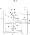
- FIG. 2 is a schematic view showing a state of the ejector unit 50 when starting ejection according to the first embodiment.
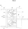
- FIG. 3 is a schematic view showing a state of the ejector unit 50 when completing ejection according to the first embodiment.
- an "ejector” is abbreviated as an "EJ”.
- EJ motor denotes an "ejector motor”.
- the injection molding machine 10 includes the ejector unit 50 used for ejecting a molding product from the movable mold 33.
- the ejector unit 50 is attached to the movable platen 13.
- the ejector unit 50 has a slide base 52 movable freely in a direction moving toward or away from an EJ toggle support 51 disposed at the movable platen 13.
- the EJ toggle support 51 may be provided as a part of the movable platen 13.
- the slide base 52 can move freely in the mold opening/closing direction (the horizontal direction in FIG. 2 ) along multiple guide rods 54, for example, four rods protruding backward from the movable platen 13.
- the ejector unit 50 also has an EJ toggle mechanism 60 disposed between the EJ toggle support 51 and the slide base 52, an EJ motor 66 as a driving source to operate the EJ toggle mechanism 60, and an EJ ball screw mechanism 67.
- the EJ ball screw mechanism 67 is a transmission mechanism to convert rotational motion generated by the EJ motor 66 into linear motion to transmit to the EJ toggle mechanism 20.
- the EJ toggle mechanism 60 also has EJ toggle arms 61 attached to the slide base 52 so that they can rotate about an axis, the first EJ toggle links 62 attached to the EJ toggle support 51 so that they can rotate about an axis. An end of the EJ toggle arm 61 and an end of the first EJ toggle link 62 are connected to each other movable rotationally. When the EJ toggle arms 61 and the first EJ toggle links 62 are extended or contracted around the connection point, the slide base 52 moves forward/backward relative to the EJ to support 51.
- EJ toggle arms 61 and the first EJ toggle links 62 may be interchanged. Namely, the EJ toggle arms 61 may be attached to the EJ toggle support 51 so that they can rotate about an axis, and the first EJ toggle links 62 may be attached to the slide base 52 so that they can rotate about an axis.
- the EJ toggle mechanism 60 also has an EJ crosshead 63 movable in a direction moving toward or away from the EJ toggle support 51, the second EJ toggle links 64 attached to the EJ crosshead 53 and the first EJ toggle links 62 so that they can rotate about an axis.
- the EJ toggle mechanism 60 is a so-called "involute five-articulation double-toggle mechanism", with a vertically symmetrical configuration. Other toggle mechanisms may be adopted.
- the EJ toggle mechanism 60 may be an evolute toggle, a single toggle, or a four-articulation toggle.
- the EJ ball screw mechanism 67 is configured with, for example, the EJ ball screw nut 67a fixed to the EJ crosshead 63, and the EJ ball screw shaft 67b screwed into the ball screw nut 67a.
- the output shaft of the EJ motor 66 and the EJ ball screw shaft 67b may be directly connected coaxially. When the output shaft of the EJ motor 66 rotates, the EJ ball screw shaft 67b rotates, which moves the EJ ball screw nut 67a forward/backward, to move the EJ crosshead 63 forward/backward.
- the output shaft of the EJ motor 66 and the EJ ball screw shaft 67b are directly connected coaxially. These may be connected, however, via a deceleration mechanism configured with multiple gears, or via a timing belt or the like.
- the EJ motor 66 may be an electric servomotor, and may have an encoder section to detect the number of rotations of the output shaft of the EJ motor 66.
- the EJ motor 66 may be feed-back-controlled based on a result detected by the encoder section.
- the EJ motor 66 may be attached to either of the EJ toggle support 51 or the slide base 52, or may be attached to the one having a shorter distance between the EJ motor 66 and the EJ crosshead 63.
- the EJ motor 66 may be attached to the EJ toggle support 51.
- the EJ motor 66 may be attached to the slide base 52. Then, the EJ ball screw shaft 67b becomes shorter, which can prevent the EJ ball screw shaft 67b from being deformed unintentionally.
- the ejector unit 50 also has an ejector rod 68 as an ejection member moving in conjunction with the slide base 52.
- the ejector rod 68 is fixed to the slide base 52, movably inserted into a through hole formed in the movable platen 13.
- the tip of the ejector rod 68 may be connected to a molding product ejection member (not shown) disposed at the movable mold 33 (see FIG. 1 ).
- the toggle mechanism 60 By driving the EJ motor 66 with forward rotation to move the EJ crosshead 63 forward, the toggle mechanism 60 operates to move the slide base 52 and the ejector rod 68 forward. As the ejector rod 68 moves forward, the mold article ejection member is ejected from the movable mold 33 to separate the molding product from the movable mold 33. After that, the ejector rod 68 further moves forward, to convey the molding product to a pick-up position.
- the toggle mechanism 60 operates to move the slide base 52 and the ejector rod 68 backward. As the ejector rod 68 moves backward, the molding product ejection member moves back to the original position.
- the ejector rod 68 can wait at an ejection start position (the position in FIG. 2 ) while the molding unit 30 is closing or clamping.
- the ejector rod 68 moves forward from the ejection start position to an ejection completion position (the position in FIG. 3 ) after the molding unit 30 opened.
- the ejector rod 68 moves back to the ejection start position.
- the ejector rod 68 may start to move forward while the molding unit 30 is opening to shorten the cycle time of molding.
- the slide base 52 is disposed at a greater distance apart from the movable mold 33 than the EJ toggle support 51. Therefore, when the ejector rod 68 moves forward from the ejection start position, the distance between 52 and the EJ toggle support 51 becomes short, and an angle ⁇ between the EJ toggle arm 61 and the first EJ toggle link 62 becomes small.
- the angle ⁇ between the EJ toggle arm 61 and the first EJ toggle link 62 becomes small. Therefore, when starting an ejection process, the ejection speed is slow and the ejection force is strong, which makes it easier to separate a molding product. After separating the molding product, the ejector rod 68 moves further forward to make the ejection speed become faster, which conveys the molding product to the pick-up position faster.
- the ejector rod 68 is fixed to the slide base 52.
- the ejector rod 68 may be fixed to, however, a middle plate (not shown) which is fixed to the slide base 52 via a connecting rod. Either of these or the like may be adopted as long as the slide base 52 and the ejector rod 68 can move together.
- the EJ rod 68 is fixed to the slide base.
- an EJ rod 168 (see FIG. 4 ) is fixed to a middle plate, which is fixed to a slide base, via connecting rods.
- the ejection member is configured with the EJ rod, the middle plate, and the connecting rods.
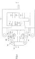
- FIG. 4 is a schematic view showing a state of an ejector unit 150 when starting ejection according to the second embodiment.
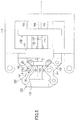
- FIG. 5 is a schematic view showing a state of the ejector unit 150 when completing ejection according to the second embodiment.
- FIG. 6 is a cross-sectional view of the ejector unit 150 taken along the line VI-VI of FIG. 4 .
- the ejector unit 150 is used for ejecting a molding product from the movable mold 33, disposed at a movable platen 113.
- the ejector unit 150 includes an EJ toggle support 151, an EJ movable platen 152 as a slide base, an EJ toggle support 160, an EJ motor 166 (see FIG. 6 ) as a driving source, and an ejection member 170.
- the EJ toggle support 151 is formed separately from the movable platen 113, fixed to the movable platen 113 with bolts or the like. Alternatively, the EJ toggle support 151 may be formed as a part of the movable platen 113. The EJ toggle support 151 has an attachment section to attach the EJ toggle support 160.
- the EJ movable platen 152 can move forward/backward relative to the EJ toggle support 151.
- the EJ movable platen 152 is disposed at a greater distance apart from the movable mold 33 (see FIG. 1 ) than the EJ toggle support 151.
- the EJ movable platen 152 has an attachment section to be attached with the EJ toggle support 160.
- the EJ toggle support 160 converts input force (propelling force generated by the EJ motor 166, specifically axial force of an EJ ball screw mechanism 167 to output force (ejection force) to transmit to the EJ movable platen 152.
- the EJ toggle support 160 is disposed between the EJ toggle support 151 and the EJ movable platen 152.
- the EJ toggle support 160 has, as shown in FIGS. 4 and 5 , EJ toggle arms 161 attached to the EJ movable platen 152 so that they can rotate about an axis and the first EJ toggle links 162 attached to the EJ toggle support 151 so that they can rotate about an axis.
- the EJ toggle arms 161 and the first EJ toggle links 162 are connected to make rotational motion relative to each other around the position point.
- the positions of the EJ toggle arms 161 the first EJ toggle links 162 may be interchanged. Namely, the EJ toggle arms 161 may be attached to the EJ toggle support 151 so that they can rotate about an axis, and the first EJ toggle links 162 may be attached to the slide base 152 so that they can rotate about an axis.
- the EJ toggle mechanism 160 also has an EJ crosshead 163 movable in the direction moving toward or away from the EJ toggle support 151, the second EJ toggle links 164 attached to the EJ crosshead 163 and the first EJ toggle links 162 so that they can rotate about an axis.
- the EJ toggle mechanism 160 is a so-called "involute five-articulation double-toggle mechanism", with a vertically symmetrical configuration. Other toggle mechanisms may be adopted.
- the EJ toggle mechanism 160 may be an evolute toggle, a single toggle, or a four-articulation toggle.
- the EJ motor 166 is a driving source to operate the EJ toggle mechanism 160.
- the EJ motor 166 is disposed, for example, at the movable platen 113.
- the position of the EJ motor 166 is not restricted specifically. Therefore it can be disposed at the EJ toggle support 151, the EJ movable platen 152, etc.
- the EJ motor 166 may have an encoder section 166a to detect the number of rotations of the output shaft of the EJ motor 166. Also, the EJ motor 166 may be connected with a current sensor 175 to detect a current supplying to the EJ motor 166.
- Rotational motion of the EJ motor 166 is converted to linear motion by the EJ ball screw mechanism 167, to transmit to the EJ toggle support 160.
- the EJ ball screw mechanism 167 is configured with, for example, the EJ ball screw nut 167a fixed to the EJ crosshead 163, the EJ ball screw shaft 167b screwed into the EJ ball screw nut 167a.
- a rotation shaft 157 (see FIG. 6 ) extended forward coaxially from the EJ ball screw mechanism 167 is attached to the EJ toggle support 151 via bearings Br or the like to be rotative. The rotation shaft 157 cannot move forward or backward relative to the EJ toggle support 151.
- the rotation shaft 157 is connected to the output shaft of the EJ motor 166 via connection members 156 such as a belt or a pulley.
- the rotation shaft 157 is connected to the output shaft of the EJ motor 166 via the connection members 156.
- the rotation shaft 157 may be connected to the output shaft of the EJ motor 166 directly.
- the toggle mechanism 160 By driving the EJ motor 166 with forward rotation to move the EJ crosshead 163 forward relative to the movable platen 33, the toggle mechanism 160 operates to move the EJ movable platen 152 forward. On the other hand, by driving the EJ motor 166 with backward rotation to move the EJ crosshead 163 backward relative to the movable platen 33, the toggle mechanism 160 operates to move the EJ movable platen 152 backward.
- the ejection member 170 is a member moving in conjunction with the EJ movable platen 152.
- the ejection member 170 is configured with, for example, an EJ plate 171 as a middle plate, EJ tie bars 172 as connection rods, and an EJ rod 168.
- the EJ plate 171 may be disposed closer to the movable mold 33 than the EJ toggle support 151, for example, at the inside of the movable platen 113.
- the EJ plate 171 is formed with a guide hole to be inserted with guide bars 153, along which the EJ plate 171 can move forward/backward.
- the rear ends of the guide bars 153 are fixed to the EJ toggle support 151, and the front ends of the guide bars 153 are fixed to the movable platen 113. Alternatively, only one of the ends may be fixed to the respective member.
- the EJ tie bars 172 are members to connect the EJ movable platen 152 and the EJ plate 171 with a certain amount of distance in-between.
- a separating force sensor 177 is provided to detect separating force of a molding product by detecting distortion of the EJ tie bar 172 generated when the molding product is separated from the movable mold 33.
- the separating force is force needed to separate a molding product from the movable mold 33, which is generated when the molding product adhering to the movable mold 33 is pushed in the ejection direction. Until the molding product is pushed in the ejection direction, the separation force is not generated while driving the EJ motor 166. If the movable mold 33 is divided into parts to make it easier to pick up a molding product, the separation force includes force to slide some parts of the movable mold 33 relative to the rest of parts of the movable mold 33.
- the separation force is detected by the separating force sensor 177 to monitor the status of mold separation.
- the separation force sensor 177 may be provided for each of the multiple EJ tie bars 172 to detect force working on the multiple EJ tie bars 172 at the same time while driving the EJ motor 166. Balance between the multiple EJ tie bars 172 can be monitored. The balance can be determined as appropriate or not, for example, whether a difference between the maximum force and the minimum force applied to the multiple EJ tie bars 172 is within a prescribed range.
- the separation force sensor 177 is configured with the distortion sensors provided at the outer circumference of the EJ tie bars 172.
- the separation force sensor 177 may be disposed between the EJ tie bar 172 and the EJ plate 171, configured with a load cell compressed when the molding product is separated from the movable mold 33.
- Type and position of the sensor is not restricted. A position of the sensor is not restricted as long as the disposed position is on a member driven by the EJ motor 166, for example, the EJ toggle support 160, the EJ ball screw mechanism 167, the EJ movable platen 152, the EJ rod 168, etc.
- the EJ tie bars 172 are inserted into the guide holes 155 at the EJ toggle support 151 to freely move forward/backward through the guide holes 155.
- Multiple guide holes 155 may be provided corresponding to the multiple EJ tie bars 172, for example, two bars, which prevents the EJ movable platen 152 from rotating forward/backward.
- the EJ tie bars 172 are also inserted into the guide holes 165 at the EJ crosshead 163 to freely move forward/backward through the guide holes 165.
- Multiple guide holes 165 may be provided corresponding to the multiple EJ tie bars 172, for example, two bars, which prevents the crosshead 163 from rotating forward/backward.
- the rear end of the EJ rod 168 is fixed to the EJ plate 171, and the front end of the EJ rod 168 may be connected to a molding product ejection member (not shown) disposed at the movable platen 33 (see FIG. 1 ).
- a molding product ejection member (not shown) disposed at the movable platen 33 (see FIG. 1 ).
- the molding product ejection member separates a molding product from the movable platen 33.
- the molding product ejection member conveys the molding product to a pick-up position. After that, by moving the EJ rod 168 backward, the molding product ejection member returns to the original position.
- the EJ plate 171 may be attached with multiple EJ rods 168.
- the ejection member 170 can wait at an ejection start position (the position in FIG. 4 ) while the molding unit 30 is closing or clamping.
- the ejection member 170 moves forward from the ejection start position to an ejection completion position (the position in FIG. 5 ) after the molding unit 30 opened. After the molding product is picked up by a take-out robot, the ejection member 170 moves back to the ejection start position.
- the ejection member 170 may start to move forward while the molding unit 30 is opening to shorten the cycle time of molding.
- the controller 190 monitors the position of the ejection member 170 relative to the movable mold 33 to supply current to the EJ motor 166 in response to the monitored result.
- the position of the ejection member 170 relative to the movable mold 33 can be calculated from a detected result by the encoder section 166a of the EJ motor 166.
- the torque of the EJ motor 166 can be calculated, for example, from a detected result by the current sensor 175.
- FIG. 7 is a graph showing a relationship between ejection force of the ejector unit 150 and the position of the ejection member 170 relative to the movable mold 33 according to the second embodiment.
- the ejection force is propelling force to move the EJ movable platen 152 and the ejection member 170 forward.
- driving force of the EJ motor 166 is unchanged, and the applied current to the EJ motor 166 is unchanged.
- FIG. 8 is a graph showing a relationship between ejection speed of the ejector unit 150 and the position of the ejection member relative to the movable mold 33 according to the second embodiment.
- the ejection speed is velocity to move the ejection member 170 forward.
- the number of rotations of the EJ motor 166 is unchanged.
- the EJ movable platen 152 is disposed at a longer distance part from the movable mold 33 than the EJ toggle support 151. Therefore, when the ejector member 170 moves forward from the ejection start position, the distance between the EJ movable platen 152 and the EJ toggle support 151 becomes short, and an angle ⁇ 100 between the centerline of the EJ toggle arm 161 and the centerline of the first EJ toggle link 162 becomes small. Therefore, in response to the forward movement of the ejection member 170, ejection characteristics changes as shown in FIGS. 7-8 .
- ejection characteristics of the ejection member 170 changes in response to the distance between the EJ toggle support and the EJ movable platen 152.
- an angle ⁇ 100 between the centerline of the EJ toggle arm 161 and the centerline of the first EJ toggle link 162 becomes small. Therefore, when starting ejection, the ejection speed is slow and the ejection force is strong, which makes it easier to separate a molding product. After separating the molding product, the ejector member 170 moves further forward to make the ejection speed become faster, which conveys the molding product to the pick-up position faster.
- the operation of the ejector unit 150 is controlled by the controller 190 (see FIG. 6 ).
- the controller 190 is configured with a CPU 191, a ROM 192, a RAM 193, a storing section 194 such as a hard disk, input interfaces, output interfaces, a timer, a counter, and the like.
- the controller 190 implements various functions by having the CPU 191 execute programs stored in the ROM 192 or the storing section 194.
- FIG. 9 is a graph showing another relationship between ejection force of the ejector unit and the position of the ejection member 170 relative to the movable mold 33 according to the second embodiment.
- driving force or the EJ motor 166 is controlled by the monitored result of the position of the ejection member 170 relative to the movable mold 33.
- the solid line shows a relationship when a restriction applied to the driving force of the EJ motor 66 is released, and the dashed line shows when a restriction is applied to the driving force of the EJ motor 66.
- the controller 190 restricts the driving force of the EJ motor 166 in the ejection direction if a prescribed condition is not met, the controller 190 releases the restriction if the prescribed condition is met.
- the driving force of the EJ motor 166 in the ejection direction may be set to a value below a restriction value set in response to the position of the ejection member 170 relative to the movable mold 33.
- the restriction value may be a value corresponding to the upper limit of the ejection force F0, for example. If the prescribed condition is not met, the driving force may be set to a value below the upper limit of the ejection force F0.
- the driving force of the EJ motor 166 in the ejection direction may be set to a value over the restriction value.
- the restriction value is set according to the position of the ejection member 170 relative to the movable mold 33. Alternatively, it may be a fixed value regardless of the position of the ejection member 170 relative to the movable mold 33.
- the prescribed range to be monitored within whether the prescribed condition is met is not restricted, but it may be, for example, the range between the ejection start position P0 and a position P1 advanced from the ejection start position P0 with a prescribed distance. Alternatively, the range may be a whole range between the ejection start position P0 and the ejection completion position, or a range around the ejection start position P0, or the like.
- the prescribed condition is not restricted, but a possible condition may be, for example, a stoppage of the ejection member 170 when the EJ motor 166 drives it in the ejection direction (the forward direction).
- a stoppage of the ejection member 170 may be determined by:
- the stoppage of the ejection member 170 may be determined by a combination of the above four criteria to improve precision of a determination. Elements and numbers of a combination are not restricted.
- the driving force of the EJ motor 166 in the ejection direction is restricted if a prescribed condition is not met, the restriction is released if the prescribed condition is met.
- the restriction is released if the prescribed condition is met.
- the molding machine 10 in the above embodiments is a horizontally oriented type in which molds are opened/closed horizontally.
- the molding unit 30 may be opened/closed vertically.
- the ejector unit 50 or 150 may be disposed at the stationary platen to be used for ejection of a molding product from the stationary mold.
- the ejector unit 50 or 150 has an electric motor as a driving source.
- the driving source is not restricted to that.
- a hydraulic motor may be used as a driving source.
- a hydraulic cylinder may be used. In the latter case, propelling force of the hydraulic cylinder may be directly transmitted to the EJ toggle mechanism 60 or 160, instead of using the EJ ball screw mechanism 67 or 167.
- the slide base 52 or 152 is disposed at a longer distance part from the movable mold 33 than the EJ toggle support 51 or 151.
- the slide base 52 or 152 may be disposed closer to the movable mold 33 than the EJ toggle support 51 or 151.
- the distance between the EJ toggle support 51 or 151 and the slide base 52 and 152 becomes longer, and the angle ⁇ or ⁇ 100 between the centerline of the EJ toggle arm 61 or 161 and the centerline of the first EJ toggle link 62 are 162 becomes larger. Therefore, compared to the above embodiments, the ejection speed becomes faster while the ejection force becomes weaker when the ejection starts.
- the EJ rod 68 or 168 is connected to the molding product ejection member disposed at the movable mold 33. Alternatively, it may not be connected to the molding product ejection member. In this case, after the ejector rod 68 or 168 has moved forward to touch the molding product ejection member, then the ejector rod 68 or 168 can move further forward to move the molding product ejection member forward. Afterwards, the molding product ejection member can move backward with a return spring disposed at the movable mold 33, which has been energized during the forward movement.
- the EJ plate 171 and the EJ rod 168 may be disposed at the movable mold 33 as parts of the molding product ejection member.
- the ejection member 170 is configured only with the EJ tie bars 172.
Landscapes
- Engineering & Computer Science (AREA)
- Manufacturing & Machinery (AREA)
- Mechanical Engineering (AREA)
- Moulds For Moulding Plastics Or The Like (AREA)
Claims (6)
- Spritzgussmaschine (10), umfassend: eine Auswurfeinheit (50, 150), eingerichtet, um ein Spritzgussprodukt aus einer Gussform (33) auszuwerfen, wobei die Auswurfeinheit (50, 150) folgendes einschließt
einen Gleitfuß (52, 152), eingerichtet, um sich relativ zu einer Kniehebelstütze (51, 151) zu bewegen, angeordnet an einem Drucktiegel (13, 130), der die Gussform (33) stützt,
einen Kniehebelmechanismus (60, 160), eingerichtet, um zwischen der Kniehebelstütze (51, 151) und dem Gleitfuß (52, 152) angeordnet zu werden,
eine Antriebsquelle (66, 166), eingerichtet, um den Kniehebelmechanismus (60, 160) zu betreiben,
ein Auswurfelement (170), bewegbar in Verbindung mit dem Gleitfuß (52, 152), dadurch gekennzeichnet, dass
die Auswurfeinheit (50, 150) weiter einen Übertragungsmechanismus (67) einschließt, um Rotationsbewegung, erzeugt durch einen elektrischen Motor (66) als der Antriebsquelle, in lineare Bewegung an den Kniehebelmechanismus (60, 160) zu übertragen. - Spritzgussmaschine (10) nach Anspruch 1,
wobei der Gleitfuß (52, 152) in einer größeren Entfernung von der Gussform angeordnet ist als die Kniehebelstütze. - Spritzgussmaschine (10) nach Anspruch 1 oder 2,
wobei das Auswurfelement (170) folgendes einschließt
eine Mittelplatte (171), angeordnet in einer bestimmten Entfernung von dem Gleitfuß,
eine Verbindungsstange (172), um den Gleitfuß (152) und die Mittelplatte (171) zu verbinden,
eine Auswurfstange (168), die mit einer Bewegung der Mittelplatte in Richtung der Gussform ausgeworfen werden soll. - Spritzgussmaschine (10) nach einem der Ansprüche 1 bis 3,
weiter umfassend eine Steuerung (190), eingerichtet, um die Antriebsquelle zu steuern,
wobei die Steuerung (190) Antriebskraft in eine Auswurfrichtung beschränkt, falls eine vorgeschriebene Bedingung nicht erfüllt ist, wohingegen die Steuerung die Beschränkung freigibt, falls die vorgeschriebene Bedingung erfüllt ist, wenn eine Position des Auswurfelements relativ zu der Gussform innerhalb eines vorgeschriebenen Bereichs ist, wobei
die vorgeschriebene Bedingung ein Stillstand des Auswurfelements (170) ist, wenn die Antriebsquelle (66, 166) das Auswurfelement in die Auswurfsrichtung antreibt. - Spritzgussmaschine (10) nach einem der Ansprüche 1 bis 4,
wobei der Kniehebelmechanismus (60, 160) einen Kniehebelarm (61, 161) einschließt, der an einem aus dem Gleitfuß (52, 152) und der Kniehebelstütze angebracht ist, sodass der Kniehebelarm um eine Achse rotieren kann, wobei ein erstes Kniehebelglied (62, 162) so an einem von dem Gleitfuß und der Kniehebelstütze angebracht ist, dass das erste Kniehebelglied um eine Achse rotieren kann, und ein Ende des Kniehebelarms und eine Ende des ersten Kniehebelglieds miteinander rotierbar beweglich verbunden sind. - Spritzgussmaschine (10) nach Anspruch 5,
wobei der Kniehebelmechanismus (60, 160) einen Kreuzkopf (63, 163), der in einer Richtung beweglich ist, die sich auf die Kniehebelstütze (51, 151) zu oder von ihr weg bewegt, ein zweites Kniehebelglied (64, 164), angebracht an dem Kreuzkopf und dem ersten Kniehebelglied (62, 162), einschließt, so dass das zweite Kniehebelglied um eine Achse rotieren kann.
Applications Claiming Priority (1)
| Application Number | Priority Date | Filing Date | Title |
|---|---|---|---|
| JP2012064512 | 2012-03-21 |
Publications (2)
| Publication Number | Publication Date |
|---|---|
| EP2641718A1 EP2641718A1 (de) | 2013-09-25 |
| EP2641718B1 true EP2641718B1 (de) | 2019-02-20 |
Family
ID=47913104
Family Applications (1)
| Application Number | Title | Priority Date | Filing Date |
|---|---|---|---|
| EP13159922.7A Active EP2641718B1 (de) | 2012-03-21 | 2013-03-19 | Spritzgiessmaschine mit einer auswerfereinheit |
Country Status (5)
| Country | Link |
|---|---|
| US (1) | US9227352B2 (de) |
| EP (1) | EP2641718B1 (de) |
| JP (1) | JP5882189B2 (de) |
| CN (1) | CN103317685B (de) |
| CA (1) | CA2810101C (de) |
Families Citing this family (8)
| Publication number | Priority date | Publication date | Assignee | Title |
|---|---|---|---|---|
| JP6125405B2 (ja) * | 2012-12-25 | 2017-05-10 | 住友重機械工業株式会社 | 射出成形機 |
| JP6117080B2 (ja) * | 2012-12-25 | 2017-04-19 | 住友重機械工業株式会社 | 射出成形機 |
| WO2018064750A1 (en) | 2016-10-05 | 2018-04-12 | Husky Injection Molding Systems Ltd. | Molding apparatus and method of controlling same |
| TWI865481B (zh) * | 2019-01-30 | 2024-12-11 | 日商京洛股份有限公司 | 成型裝置、以及成型品的製造系統 |
| JP7368187B2 (ja) * | 2019-10-31 | 2023-10-24 | ファナック株式会社 | 射出成形機 |
| JP6967638B1 (ja) * | 2020-08-27 | 2021-11-17 | 株式会社ソディック | 射出成形機の型締装置 |
| JP7757867B2 (ja) * | 2022-04-25 | 2025-10-22 | トヨタ自動車株式会社 | 金型装置 |
| JP2024006517A (ja) * | 2022-07-04 | 2024-01-17 | 株式会社日本製鋼所 | 型締装置および射出成形機、ならびに型締方法 |
Family Cites Families (9)
| Publication number | Priority date | Publication date | Assignee | Title |
|---|---|---|---|---|
| US3726625A (en) * | 1971-02-16 | 1973-04-10 | Husky Mfg Tool Works Ltd | Ejector mechanism for molded articles |
| IT976729B (it) * | 1973-02-16 | 1974-09-10 | Mainetti Spa | Dispositivo per ottenere l estra zione anticipata del pezzo in una pressa per stampaggio ad iniezio ne di materie plastiche e presso fusione |
| JPH04168018A (ja) | 1990-11-01 | 1992-06-16 | Fanuc Ltd | エジェクト装置 |
| JP3586483B2 (ja) * | 1994-10-26 | 2004-11-10 | ファナック株式会社 | 射出成形機のエジェクト装置 |
| JP3232510B2 (ja) * | 1999-03-16 | 2001-11-26 | 住友重機械工業株式会社 | 電動式竪型射出成形機のエジェクタ装置 |
| KR100642880B1 (ko) * | 1999-05-03 | 2006-11-10 | 밀라크론 인코포레이티드 | 사출 성형된 부분을 추출하기 위한 전기적으로 구동되는장치 |
| JP4139335B2 (ja) | 2004-01-13 | 2008-08-27 | 住友重機械工業株式会社 | 射出成形機 |
| US20080211126A1 (en) * | 2005-03-16 | 2008-09-04 | Sumitomo Heavy Industries, Ltd. | Molding Condition Setting Method and Control Method of Injection Molding Machine |
| DE102010034451B4 (de) | 2009-08-25 | 2013-07-04 | Engel Austria Gmbh | Auswerfervorrichtung mit Zusatz-Auswerferkraft |
-
2012
- 2012-12-25 JP JP2012281564A patent/JP5882189B2/ja active Active
-
2013
- 2013-01-29 CN CN201310033832.9A patent/CN103317685B/zh active Active
- 2013-03-15 US US13/834,255 patent/US9227352B2/en not_active Expired - Fee Related
- 2013-03-19 EP EP13159922.7A patent/EP2641718B1/de active Active
- 2013-03-19 CA CA2810101A patent/CA2810101C/en active Active
Non-Patent Citations (1)
| Title |
|---|
| None * |
Also Published As
| Publication number | Publication date |
|---|---|
| US20130251837A1 (en) | 2013-09-26 |
| JP2013224011A (ja) | 2013-10-31 |
| US9227352B2 (en) | 2016-01-05 |
| CA2810101A1 (en) | 2013-09-21 |
| JP5882189B2 (ja) | 2016-03-09 |
| CN103317685A (zh) | 2013-09-25 |
| CA2810101C (en) | 2015-06-30 |
| CN103317685B (zh) | 2016-04-27 |
| EP2641718A1 (de) | 2013-09-25 |
Similar Documents
| Publication | Publication Date | Title |
|---|---|---|
| EP2641718B1 (de) | Spritzgiessmaschine mit einer auswerfereinheit | |
| EP2749392B1 (de) | Spritzgiessmaschine mit einer auswerfereinheit | |
| CN108068282B (zh) | 成型机 | |
| EP3135455B1 (de) | Einspritzeinheit | |
| CN101111359A (zh) | 成形条件设定方法以及射出成形机的控制方法 | |
| EP2749391B1 (de) | Spritzgiessmaschine | |
| JP2018140610A (ja) | 射出成形機 | |
| JP2001349407A (ja) | ボールねじの異常検出装置 | |
| JP5723676B2 (ja) | 型締装置、成形機、型締装置の制御方法 | |
| JP6385831B2 (ja) | 射出成形機 | |
| EP3173209B1 (de) | Einspritzeinheit | |
| JP6696863B2 (ja) | 射出成形機 | |
| CN113459442B (zh) | 注塑成型机 | |
| US20090026644A1 (en) | Control Device for Molding Machine, Control Method for Molding Machine, and Molding Machine | |
| CN114953372B (zh) | 注射成型机 | |
| JP6751134B2 (ja) | 射出成形機 | |
| JP4153466B2 (ja) | 電動射出成形機の射出装置 | |
| JP2018069316A (ja) | 電動ダイカストマシンおよびその制御方法 | |
| JP5226191B2 (ja) | 成形機及びその制御方法 | |
| JP6716154B2 (ja) | 射出成形機 | |
| KR20170001019A (ko) | 사출 성형기 | |
| JP2018164921A (ja) | 電動ダイカストマシンおよびその制御方法 | |
| JP2004106279A (ja) | エジェクタピンの突出し方法 |
Legal Events
| Date | Code | Title | Description |
|---|---|---|---|
| PUAI | Public reference made under article 153(3) epc to a published international application that has entered the european phase |
Free format text: ORIGINAL CODE: 0009012 |
|
| AK | Designated contracting states |
Kind code of ref document: A1 Designated state(s): AL AT BE BG CH CY CZ DE DK EE ES FI FR GB GR HR HU IE IS IT LI LT LU LV MC MK MT NL NO PL PT RO RS SE SI SK SM TR |
|
| AX | Request for extension of the european patent |
Extension state: BA ME |
|
| 17P | Request for examination filed |
Effective date: 20140206 |
|
| RBV | Designated contracting states (corrected) |
Designated state(s): AL AT BE BG CH CY CZ DE DK EE ES FI FR GB GR HR HU IE IS IT LI LT LU LV MC MK MT NL NO PL PT RO RS SE SI SK SM TR |
|
| GRAP | Despatch of communication of intention to grant a patent |
Free format text: ORIGINAL CODE: EPIDOSNIGR1 |
|
| STAA | Information on the status of an ep patent application or granted ep patent |
Free format text: STATUS: GRANT OF PATENT IS INTENDED |
|
| INTG | Intention to grant announced |
Effective date: 20181001 |
|
| GRAS | Grant fee paid |
Free format text: ORIGINAL CODE: EPIDOSNIGR3 |
|
| GRAA | (expected) grant |
Free format text: ORIGINAL CODE: 0009210 |
|
| STAA | Information on the status of an ep patent application or granted ep patent |
Free format text: STATUS: THE PATENT HAS BEEN GRANTED |
|
| AK | Designated contracting states |
Kind code of ref document: B1 Designated state(s): AL AT BE BG CH CY CZ DE DK EE ES FI FR GB GR HR HU IE IS IT LI LT LU LV MC MK MT NL NO PL PT RO RS SE SI SK SM TR |
|
| REG | Reference to a national code |
Ref country code: GB Ref legal event code: FG4D |
|
| REG | Reference to a national code |
Ref country code: CH Ref legal event code: EP |
|
| REG | Reference to a national code |
Ref country code: DE Ref legal event code: R096 Ref document number: 602013050889 Country of ref document: DE |
|
| REG | Reference to a national code |
Ref country code: AT Ref legal event code: REF Ref document number: 1097608 Country of ref document: AT Kind code of ref document: T Effective date: 20190315 |
|
| REG | Reference to a national code |
Ref country code: IE Ref legal event code: FG4D |
|
| REG | Reference to a national code |
Ref country code: CH Ref legal event code: NV Representative=s name: NOVAGRAAF INTERNATIONAL SA, CH |
|
| REG | Reference to a national code |
Ref country code: NL Ref legal event code: MP Effective date: 20190220 |
|
| REG | Reference to a national code |
Ref country code: LT Ref legal event code: MG4D |
|
| PG25 | Lapsed in a contracting state [announced via postgrant information from national office to epo] |
Ref country code: FI Free format text: LAPSE BECAUSE OF FAILURE TO SUBMIT A TRANSLATION OF THE DESCRIPTION OR TO PAY THE FEE WITHIN THE PRESCRIBED TIME-LIMIT Effective date: 20190220 Ref country code: PT Free format text: LAPSE BECAUSE OF FAILURE TO SUBMIT A TRANSLATION OF THE DESCRIPTION OR TO PAY THE FEE WITHIN THE PRESCRIBED TIME-LIMIT Effective date: 20190620 Ref country code: NO Free format text: LAPSE BECAUSE OF FAILURE TO SUBMIT A TRANSLATION OF THE DESCRIPTION OR TO PAY THE FEE WITHIN THE PRESCRIBED TIME-LIMIT Effective date: 20190520 Ref country code: NL Free format text: LAPSE BECAUSE OF FAILURE TO SUBMIT A TRANSLATION OF THE DESCRIPTION OR TO PAY THE FEE WITHIN THE PRESCRIBED TIME-LIMIT Effective date: 20190220 Ref country code: SE Free format text: LAPSE BECAUSE OF FAILURE TO SUBMIT A TRANSLATION OF THE DESCRIPTION OR TO PAY THE FEE WITHIN THE PRESCRIBED TIME-LIMIT Effective date: 20190220 Ref country code: LT Free format text: LAPSE BECAUSE OF FAILURE TO SUBMIT A TRANSLATION OF THE DESCRIPTION OR TO PAY THE FEE WITHIN THE PRESCRIBED TIME-LIMIT Effective date: 20190220 |
|
| PG25 | Lapsed in a contracting state [announced via postgrant information from national office to epo] |
Ref country code: HR Free format text: LAPSE BECAUSE OF FAILURE TO SUBMIT A TRANSLATION OF THE DESCRIPTION OR TO PAY THE FEE WITHIN THE PRESCRIBED TIME-LIMIT Effective date: 20190220 Ref country code: GR Free format text: LAPSE BECAUSE OF FAILURE TO SUBMIT A TRANSLATION OF THE DESCRIPTION OR TO PAY THE FEE WITHIN THE PRESCRIBED TIME-LIMIT Effective date: 20190521 Ref country code: LV Free format text: LAPSE BECAUSE OF FAILURE TO SUBMIT A TRANSLATION OF THE DESCRIPTION OR TO PAY THE FEE WITHIN THE PRESCRIBED TIME-LIMIT Effective date: 20190220 Ref country code: IS Free format text: LAPSE BECAUSE OF FAILURE TO SUBMIT A TRANSLATION OF THE DESCRIPTION OR TO PAY THE FEE WITHIN THE PRESCRIBED TIME-LIMIT Effective date: 20190620 Ref country code: RS Free format text: LAPSE BECAUSE OF FAILURE TO SUBMIT A TRANSLATION OF THE DESCRIPTION OR TO PAY THE FEE WITHIN THE PRESCRIBED TIME-LIMIT Effective date: 20190220 Ref country code: BG Free format text: LAPSE BECAUSE OF FAILURE TO SUBMIT A TRANSLATION OF THE DESCRIPTION OR TO PAY THE FEE WITHIN THE PRESCRIBED TIME-LIMIT Effective date: 20190520 |
|
| PG25 | Lapsed in a contracting state [announced via postgrant information from national office to epo] |
Ref country code: DK Free format text: LAPSE BECAUSE OF FAILURE TO SUBMIT A TRANSLATION OF THE DESCRIPTION OR TO PAY THE FEE WITHIN THE PRESCRIBED TIME-LIMIT Effective date: 20190220 Ref country code: IT Free format text: LAPSE BECAUSE OF FAILURE TO SUBMIT A TRANSLATION OF THE DESCRIPTION OR TO PAY THE FEE WITHIN THE PRESCRIBED TIME-LIMIT Effective date: 20190220 Ref country code: RO Free format text: LAPSE BECAUSE OF FAILURE TO SUBMIT A TRANSLATION OF THE DESCRIPTION OR TO PAY THE FEE WITHIN THE PRESCRIBED TIME-LIMIT Effective date: 20190220 Ref country code: CZ Free format text: LAPSE BECAUSE OF FAILURE TO SUBMIT A TRANSLATION OF THE DESCRIPTION OR TO PAY THE FEE WITHIN THE PRESCRIBED TIME-LIMIT Effective date: 20190220 Ref country code: EE Free format text: LAPSE BECAUSE OF FAILURE TO SUBMIT A TRANSLATION OF THE DESCRIPTION OR TO PAY THE FEE WITHIN THE PRESCRIBED TIME-LIMIT Effective date: 20190220 Ref country code: AL Free format text: LAPSE BECAUSE OF FAILURE TO SUBMIT A TRANSLATION OF THE DESCRIPTION OR TO PAY THE FEE WITHIN THE PRESCRIBED TIME-LIMIT Effective date: 20190220 Ref country code: ES Free format text: LAPSE BECAUSE OF FAILURE TO SUBMIT A TRANSLATION OF THE DESCRIPTION OR TO PAY THE FEE WITHIN THE PRESCRIBED TIME-LIMIT Effective date: 20190220 Ref country code: SK Free format text: LAPSE BECAUSE OF FAILURE TO SUBMIT A TRANSLATION OF THE DESCRIPTION OR TO PAY THE FEE WITHIN THE PRESCRIBED TIME-LIMIT Effective date: 20190220 |
|
| REG | Reference to a national code |
Ref country code: DE Ref legal event code: R097 Ref document number: 602013050889 Country of ref document: DE |
|
| PG25 | Lapsed in a contracting state [announced via postgrant information from national office to epo] |
Ref country code: LU Free format text: LAPSE BECAUSE OF NON-PAYMENT OF DUE FEES Effective date: 20190319 Ref country code: PL Free format text: LAPSE BECAUSE OF FAILURE TO SUBMIT A TRANSLATION OF THE DESCRIPTION OR TO PAY THE FEE WITHIN THE PRESCRIBED TIME-LIMIT Effective date: 20190220 Ref country code: SM Free format text: LAPSE BECAUSE OF FAILURE TO SUBMIT A TRANSLATION OF THE DESCRIPTION OR TO PAY THE FEE WITHIN THE PRESCRIBED TIME-LIMIT Effective date: 20190220 |
|
| REG | Reference to a national code |
Ref country code: BE Ref legal event code: MM Effective date: 20190331 |
|
| PLBE | No opposition filed within time limit |
Free format text: ORIGINAL CODE: 0009261 |
|
| STAA | Information on the status of an ep patent application or granted ep patent |
Free format text: STATUS: NO OPPOSITION FILED WITHIN TIME LIMIT |
|
| PG25 | Lapsed in a contracting state [announced via postgrant information from national office to epo] |
Ref country code: MC Free format text: LAPSE BECAUSE OF FAILURE TO SUBMIT A TRANSLATION OF THE DESCRIPTION OR TO PAY THE FEE WITHIN THE PRESCRIBED TIME-LIMIT Effective date: 20190220 |
|
| 26N | No opposition filed |
Effective date: 20191121 |
|
| GBPC | Gb: european patent ceased through non-payment of renewal fee |
Effective date: 20190520 |
|
| PG25 | Lapsed in a contracting state [announced via postgrant information from national office to epo] |
Ref country code: IE Free format text: LAPSE BECAUSE OF NON-PAYMENT OF DUE FEES Effective date: 20190319 |
|
| PG25 | Lapsed in a contracting state [announced via postgrant information from national office to epo] |
Ref country code: FR Free format text: LAPSE BECAUSE OF NON-PAYMENT OF DUE FEES Effective date: 20190420 Ref country code: SI Free format text: LAPSE BECAUSE OF FAILURE TO SUBMIT A TRANSLATION OF THE DESCRIPTION OR TO PAY THE FEE WITHIN THE PRESCRIBED TIME-LIMIT Effective date: 20190220 Ref country code: BE Free format text: LAPSE BECAUSE OF NON-PAYMENT OF DUE FEES Effective date: 20190331 |
|
| PG25 | Lapsed in a contracting state [announced via postgrant information from national office to epo] |
Ref country code: TR Free format text: LAPSE BECAUSE OF FAILURE TO SUBMIT A TRANSLATION OF THE DESCRIPTION OR TO PAY THE FEE WITHIN THE PRESCRIBED TIME-LIMIT Effective date: 20190220 |
|
| PG25 | Lapsed in a contracting state [announced via postgrant information from national office to epo] |
Ref country code: GB Free format text: LAPSE BECAUSE OF NON-PAYMENT OF DUE FEES Effective date: 20190520 |
|
| PG25 | Lapsed in a contracting state [announced via postgrant information from national office to epo] |
Ref country code: MT Free format text: LAPSE BECAUSE OF NON-PAYMENT OF DUE FEES Effective date: 20190319 |
|
| REG | Reference to a national code |
Ref country code: AT Ref legal event code: UEP Ref document number: 1097608 Country of ref document: AT Kind code of ref document: T Effective date: 20190220 |
|
| PG25 | Lapsed in a contracting state [announced via postgrant information from national office to epo] |
Ref country code: CY Free format text: LAPSE BECAUSE OF FAILURE TO SUBMIT A TRANSLATION OF THE DESCRIPTION OR TO PAY THE FEE WITHIN THE PRESCRIBED TIME-LIMIT Effective date: 20190220 |
|
| PG25 | Lapsed in a contracting state [announced via postgrant information from national office to epo] |
Ref country code: HU Free format text: LAPSE BECAUSE OF FAILURE TO SUBMIT A TRANSLATION OF THE DESCRIPTION OR TO PAY THE FEE WITHIN THE PRESCRIBED TIME-LIMIT; INVALID AB INITIO Effective date: 20130319 |
|
| PGFP | Annual fee paid to national office [announced via postgrant information from national office to epo] |
Ref country code: CH Payment date: 20220215 Year of fee payment: 10 Ref country code: AT Payment date: 20220225 Year of fee payment: 10 |
|
| PG25 | Lapsed in a contracting state [announced via postgrant information from national office to epo] |
Ref country code: MK Free format text: LAPSE BECAUSE OF FAILURE TO SUBMIT A TRANSLATION OF THE DESCRIPTION OR TO PAY THE FEE WITHIN THE PRESCRIBED TIME-LIMIT Effective date: 20190220 |
|
| REG | Reference to a national code |
Ref country code: CH Ref legal event code: PL |
|
| REG | Reference to a national code |
Ref country code: AT Ref legal event code: MM01 Ref document number: 1097608 Country of ref document: AT Kind code of ref document: T Effective date: 20230319 |
|
| PG25 | Lapsed in a contracting state [announced via postgrant information from national office to epo] |
Ref country code: LI Free format text: LAPSE BECAUSE OF NON-PAYMENT OF DUE FEES Effective date: 20230331 Ref country code: CH Free format text: LAPSE BECAUSE OF NON-PAYMENT OF DUE FEES Effective date: 20230331 Ref country code: AT Free format text: LAPSE BECAUSE OF NON-PAYMENT OF DUE FEES Effective date: 20230319 |
|
| PGFP | Annual fee paid to national office [announced via postgrant information from national office to epo] |
Ref country code: DE Payment date: 20260128 Year of fee payment: 14 |