EP2641713A2 - Betongussformsystem - Google Patents
Betongussformsystem Download PDFInfo
- Publication number
- EP2641713A2 EP2641713A2 EP13160300.3A EP13160300A EP2641713A2 EP 2641713 A2 EP2641713 A2 EP 2641713A2 EP 13160300 A EP13160300 A EP 13160300A EP 2641713 A2 EP2641713 A2 EP 2641713A2
- Authority
- EP
- European Patent Office
- Prior art keywords
- support
- base plate
- edge
- casting mold
- concrete casting
- Prior art date
- Legal status (The legal status is an assumption and is not a legal conclusion. Google has not performed a legal analysis and makes no representation as to the accuracy of the status listed.)
- Granted
Links
Images


Classifications
-
- B—PERFORMING OPERATIONS; TRANSPORTING
- B28—WORKING CEMENT, CLAY, OR STONE
- B28B—SHAPING CLAY OR OTHER CERAMIC COMPOSITIONS; SHAPING SLAG; SHAPING MIXTURES CONTAINING CEMENTITIOUS MATERIAL, e.g. PLASTER
- B28B7/00—Moulds; Cores; Mandrels
- B28B7/0002—Auxiliary parts or elements of the mould
- B28B7/0014—Fastening means for mould parts, e.g. for attaching mould walls on mould tables; Mould clamps
- B28B7/0017—Fastening means for mould parts, e.g. for attaching mould walls on mould tables; Mould clamps for attaching mould walls on mould tables
-
- B—PERFORMING OPERATIONS; TRANSPORTING
- B28—WORKING CEMENT, CLAY, OR STONE
- B28B—SHAPING CLAY OR OTHER CERAMIC COMPOSITIONS; SHAPING SLAG; SHAPING MIXTURES CONTAINING CEMENTITIOUS MATERIAL, e.g. PLASTER
- B28B7/00—Moulds; Cores; Mandrels
- B28B7/0002—Auxiliary parts or elements of the mould
- B28B7/0014—Fastening means for mould parts, e.g. for attaching mould walls on mould tables; Mould clamps
- B28B7/002—Fastening means for mould parts, e.g. for attaching mould walls on mould tables; Mould clamps using magnets
-
- E—FIXED CONSTRUCTIONS
- E04—BUILDING
- E04G—SCAFFOLDING; FORMS; SHUTTERING; BUILDING IMPLEMENTS OR AIDS, OR THEIR USE; HANDLING BUILDING MATERIALS ON THE SITE; REPAIRING, BREAKING-UP OR OTHER WORK ON EXISTING BUILDINGS
- E04G17/00—Connecting or other auxiliary members for forms, falsework structures, or shutterings
Definitions
- the invention relates to the concrete casting mold system defined in the preamble of claim 1.
- patent publication EP1075917 One example of prior art is disclosed in patent publication EP1075917 .
- the mold is supported by a magnet to a lower metal plate.
- the lower part of the outer surface of the mold is provided with an upwardly directed projection and the magnetic piece has a downwardly directed complementary projection.
- the projections can be locked to one another in such a way that the magnet supports and presses down the mold and keeps it in place when locked onto the metal plate.
- the projection being used for locking may be provided in the mold itself or it is possible to fasten a rail or other profile over the length of the outer surface of the mold to provide said projection.
- the system according to the publication is functional and easy to use.
- it has certain defects and drawbacks.
- Casting molds of different sizes are continuously made and disassembled at the production plant, so the same parts of the mold are always reused with appropriate sizing.
- the molds must be made of suitable machineable material, such as strong plywood plate.
- the locking projection must extend over the entire width of the mold so as always to provide the support to the appropriate location. If the locking projection is made in the mold, the mold becomes relatively expensive, particularly as the molds constitute in any case wearable articles that must always be sawn to suit new casting projects.
- the locking projections are made for example in a separate aluminum profile fastened to the outer surface of the mold, the profiles must also be cut.
- the objective of the invention is to remedy the above-mentioned defects of the prior art.
- the objective of the invention is to disclose a novel casting mold structure system to speed up the mold building work and the assembly and disassembly work and allow reuse of the mold structures.
- the concrete casting mold system includes a base plate and a number of edge plates that are perpendicular to the base plate and delimit the mold being cast on the base plate.
- the mold includes a number of support members being fastened on the base plate and supported to the edge plates outside the mold to be cast for supporting the edge plates and keeping them in place for the duration of the casting and curing.
- the concrete casting mold system includes an angular support, constituting a rigid body, in connection with each support member.
- the angular support has a fastening part that is perpendicular to the base plate and fastened to the outer surface of the edge plate in the direction thereof and a support part that is perpendicular to the base plate and to the fastening part and supported by the lower edge on the base plate.
- a support shoulder is provided to the lower part of the angular support, i.e. close to the lower edge thereof, for supporting the support member.
- the position of the support shoulder in the angular support is determined by a complementary shoulder provided in the support member and by the position thereof, such that the support member would tightly lock the angular support in place while the support member itself is fastened in place on the base plate.
- the base plate is made of metal of suitable magnetic material, in which case the support member includes a strong magnet for fastening the support member in place in an immobile fashion.
- the base plate is made of a wood-based plate, such as strong plywood, in which case the support member can be screwed, nailed, bolted or fastened in any other manner known per se in place to the base plate in such a way as to hold the angular support in place, which in turn will hold the edge plate of the mold in place and in an upright position.
- a wood-based plate such as strong plywood
- the support member can be screwed, nailed, bolted or fastened in any other manner known per se in place to the base plate in such a way as to hold the angular support in place, which in turn will hold the edge plate of the mold in place and in an upright position.
- other base plate materials that allow screwing, nailing, bolting and any suchlike fastening may be considered, such as different plastic-based plates.
- the support shoulder is provided to the lower edge of the fastening part of the angular support.
- the magnet or other support member locks the fastening part of the angular support being fastened to the edge plate of the mold in place while the support member may give, depending on its structure, also vertical support for the edge plate.
- the support shoulder is provided to the lower edge of the support part.
- the angular support is fastened to the edge plate by the fastening part and the support part of the angular support gives vertical support for the edge plate as it is supported to the base plate.
- the support member thus locks and presses the support part of the angular support in place against the base plate, preventing it from moving.
- the support shoulder is provided to the lower edge of the fastening part and the support part both.
- the fastening part and the support part are identical plates.
- the angular support is formed by two identical plates that are perpendicular to one another.
- a magnet or other support member can always be fastened alternatively to either one of the parts as required by the existing space and support needed.
- either one of the plates can be freely selected as the support part and as the fastening part in the angular support, meaning that the angular support can be fastened to the edge plate of the mold by either one of the parts, while the other part acts as the support part that is perpendicular thereto.
- the angular support is made by bending a straight steel sheet into a rectangular shape in such a way that the fastening part and the support part are provided perpendicular to one another and consist of straight and uniformly thick plates.
- the thickness of the steel plate being used preferably ranges from 5 to 10 mm but of course may vary according to the need for support.
- a simple, secure and easy to use way of fastening the angular support to the edge plate of the mold is screwing.
- a number of holes are preferably provided to the fastening part of the angular support, for example with suitable spacing over the entire area thereof. This way, it is always possible to select a sufficient number of holes for fastening in suitable positions for screwing.
- the best material for the edge plate of the mold is plywood.
- the sufficient density for the angular supports is approximately 1m.
- Plywood is rigid and allows cleaning and washing as well as several times of screwing so that the same plywood can be used a number of times in different molds just by sizing and sawing it to the dimensions of the new mold.
- the lower edges of the fastening part and the support part of the angular support that has been bent out of a single plate or welded together out of two plates are aligned straight edges so as to have the angular support supported tightly and without play for the entire length of the lower edge thereof directly on the base plate. This way, it provides the best support for the edge of the mold.
- the support member has a complementary shoulder that corresponds to the support shoulder of the angular support.
- their shapes correspond to one another in such a way that the complementary shoulder of the support member can be installed on the support shoulder of the angular support provided in place on the base plate.
- the support shoulder and the complementary shoulder tightly lock to one another, so that in fastening the support member to the base plate, the angular support is also fastened in place rigidly.
- the angular supports may have different heights and widths as required by the dimensions of the mold being used.
- the height of the angular support is appropriately at least half of the height of a corresponding edge plate, preferably substantially equally high as the corresponding edge plate. Accordingly, its length extending out of the mold being supported becomes appropriately greater as the mold becomes higher.
- the concrete casting mold system according to the invention provides considerable advantages as compared with the prior art.
- the angular support of the concrete casting mold is very simple to fasten and use. Likewise, it can be quickly disassembled. It can be fastened to a freely selected place and with a freely selected density.
- the angular support provides effective support for the edge plate of a casting mold in the length direction, transverse direction and circular direction of the mold. For example, when molding window openings in the middle of the mold, the saving of time achieved by the invention is approximately 80% in comparison to the traditional mold-making.
- the structure permits to support the inner corners of the mold simply by a single angular support.
- the structure practically entirely eliminates the production of waste material in disassembling the molds because the angular supports, support members and any fastening screws or the like needed are completely reusable and, when cleaned and washed, the edge plates of the molds constitute plate material that is as good as new when the new molds are made.
- Fig. 1 illustrates one angular support 4 according to the invention that is applicable for the concrete casting mold system according to the invention. It has been bent out of a single steel plate into a rectangular shape in such a way as to consist of a fastening part 5 and a support part 6.
- the fastening part and the support part are identical plates in terms of their shape and size.
- the fastening part 5 has a number of holes 8 for screwing the angular support onto the edge plate of the mold.
- a wide opening 9 extends into both of the parts of the angular support over the angle so as to act as a gripping handle for facilitating the handling of the angular support and also to have a structurally lightening effect.
- a rail having an upwardly sloping angle is fastened to the lower edge of both of the parts 5 and 6 of the angular support so as to form a support shoulder 7 to the upper edge thereof, allowing the downward fastening in place of the support shoulder by a permanent magnet and by a complementary shoulder provided therein.
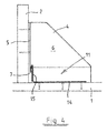
- Fig. 2 illustrates a more detailed view of the use of the angular support 4 according to Fig. 1 in a concrete casting mold.
- the concrete casting mold includes a steel base plate 1 on which the shape of a piece to be cast is delimited by edge plates 2.
- edge plates 2 In order to hold the edge plates 2 in place and straight during the casting, they are supported vertically by angular supports 4.
- the angular support 4 is placed on the base plate 1 in such a way that a plate-type fastening part 5 is provided against the edge plate 2.
- a plate-type support part 6 of the angular support extends perpendicularly outward from the edge plate while being supported on the base plate.
- the fastening part 5 is screwed by screws through holes 8 provided therein onto the plywood edge plate.
- a fastening magnet 3 equipped with a permanent magnet is provided and raised against the fastening part 5 of the angular support 4 in such a way that a complementary shoulder 10 in the magnet is disposed on a support shoulder 7 in the fastening part 5.
- They have been sized in such a way as to tightly fit against one another while the base of the magnet 3 stably rests on the base plate 1.
- Fig. 3 illustrates one preferred embodiment of the invention.
- wall molds often have, in the middle of the mold that is delimited by edge plates, auxiliary molds for windows or doors that must be supported from the inside, unlike the edge plates that are supported from the outside.
- the angular supports 4 be screwed onto the corners of the mold and then fastened to the base plate 1 with a magnet by the support shoulder 7 at the lower edge.
- Such a mold with openings is extremely simple to manufacture, to lock in place and to remove after curing of the cast.
- Fig. 4 and 5 illustrate an embodiment of the invention wherein a metal plate is not used as the base plate 1, in which case a magnet cannot be used as a support member.
- the base plate 1 may be plywood, particle board, any other wood-based plate, a plate based on plastic material etc.
- the angular support 4 according to Fig. 1 is fastened by the fastening part 5 to the edge plate 2 supported to the base plate 1, while the support part 6 extends perpendicularly away from the edge plate 2.
- the support member 11 used for the angular support is a structure bent out of a metal plate, wherein a straight plate-type part 14 provided with a number of fastening sockets, i.e. holes 12, is screwed or nailed to the base plate 1.
- One edge 15 of the plate-type part is upwardly bent at a right angle so that the edge extends over the support shoulder 7 of the angular support 4.
- the edge is slopingly bent down in such a way that a slopingly down extending tongue, i.e. a complementary shoulder 13, is formed to the upper part of the edge 15.
- the complementary shoulder 13 suitably corresponds to the support shoulder in shape in such a way that, when set against one another, the angular support 4 is locked in place while the support member 11 is fastened to the base 1.
- Sufficient rigidity and locking is achieved by selecting a sufficiently rigid and thick metal plate as manufacturing material for the support member 11.
- the base plate 1 is for example a wood-based plate. It is very simple and easy to make and gives good support for the angular support.
- the support member used may be, in terms of shape and material, a piece or structure of even great variation with the common feature of having a complementary shoulder that corresponds to the support shoulder 7 and can be attached thereto, and being able to be fastened, such as screwed, nailed, bolted, stably in place to the base plate next to the angular support.
- Fig. 6 illustrates one embodiment of the invention wherein, for example, the edges of a window opening in an element being made are provided on a slight slant.
- an adjustment piece i.e. for example a small piece of plywood, close to the upper edge of the angular support between the fastening part 5 of the angular support and the edge plate 2 of the mold.
- the adjustment piece suitably turns the edge plate to a slightly slanted angle.
- the fastening part 5 is further screwed to the edge plate 2 through the adjustment piece, the adjustment piece will stay in place for the duration of casting.
Landscapes
- Engineering & Computer Science (AREA)
- Mechanical Engineering (AREA)
- Manufacturing & Machinery (AREA)
- Chemical & Material Sciences (AREA)
- Ceramic Engineering (AREA)
- Architecture (AREA)
- Civil Engineering (AREA)
- Structural Engineering (AREA)
- Forms Removed On Construction Sites Or Auxiliary Members Thereof (AREA)
- On-Site Construction Work That Accompanies The Preparation And Application Of Concrete (AREA)
Applications Claiming Priority (1)
| Application Number | Priority Date | Filing Date | Title |
|---|---|---|---|
| FI20125325A FI123795B (fi) | 2012-03-22 | 2012-03-22 | Betonivalumuottijärjestelmä |
Publications (3)
| Publication Number | Publication Date |
|---|---|
| EP2641713A2 true EP2641713A2 (de) | 2013-09-25 |
| EP2641713A3 EP2641713A3 (de) | 2014-09-03 |
| EP2641713B1 EP2641713B1 (de) | 2017-06-07 |
Family
ID=47901851
Family Applications (1)
| Application Number | Title | Priority Date | Filing Date |
|---|---|---|---|
| EP13160300.3A Not-in-force EP2641713B1 (de) | 2012-03-22 | 2013-03-21 | Betongussformsystem |
Country Status (2)
| Country | Link |
|---|---|
| EP (1) | EP2641713B1 (de) |
| FI (1) | FI123795B (de) |
Cited By (2)
| Publication number | Priority date | Publication date | Assignee | Title |
|---|---|---|---|---|
| CN114033174A (zh) * | 2021-09-24 | 2022-02-11 | 上海建工建材科技集团股份有限公司 | 一种口字形混凝土浇筑模具及其浇筑方法 |
| US20230203827A1 (en) * | 2021-12-28 | 2023-06-29 | OCM, Inc. | Tilt-form bracket for concrete wall construction |
Citations (1)
| Publication number | Priority date | Publication date | Assignee | Title |
|---|---|---|---|---|
| EP1075917A2 (de) | 1999-08-09 | 2001-02-14 | Addtek Research & Development Oy Ab | Abnehmbare Seitenwandanordnung für eine Form zum Giessen von Beton |
Family Cites Families (5)
| Publication number | Priority date | Publication date | Assignee | Title |
|---|---|---|---|---|
| DE7305104U (de) * | 1973-02-10 | 1973-05-30 | Mannesmann Leichtbau Gmbh | Gießform zur Herstellung von Fertigbauteilen |
| NO954164L (no) * | 1994-11-11 | 1996-05-13 | Atle Laland | Forskalingsramme |
| US5766645A (en) * | 1996-10-16 | 1998-06-16 | Sci Sitecast International, Inc. | Concrete forming system for stack construction |
| US7828263B2 (en) * | 2004-07-22 | 2010-11-09 | Dayton Superior Corporation | Concrete form brace and battering wedge |
| NZ581895A (en) * | 2006-11-14 | 2012-07-27 | Itw Australia Pty Ltd | Magnetic mounting bracket for precast concrete sideforms |
-
2012
- 2012-03-22 FI FI20125325A patent/FI123795B/fi not_active IP Right Cessation
-
2013
- 2013-03-21 EP EP13160300.3A patent/EP2641713B1/de not_active Not-in-force
Patent Citations (1)
| Publication number | Priority date | Publication date | Assignee | Title |
|---|---|---|---|---|
| EP1075917A2 (de) | 1999-08-09 | 2001-02-14 | Addtek Research & Development Oy Ab | Abnehmbare Seitenwandanordnung für eine Form zum Giessen von Beton |
Cited By (3)
| Publication number | Priority date | Publication date | Assignee | Title |
|---|---|---|---|---|
| CN114033174A (zh) * | 2021-09-24 | 2022-02-11 | 上海建工建材科技集团股份有限公司 | 一种口字形混凝土浇筑模具及其浇筑方法 |
| US20230203827A1 (en) * | 2021-12-28 | 2023-06-29 | OCM, Inc. | Tilt-form bracket for concrete wall construction |
| US11988000B2 (en) * | 2021-12-28 | 2024-05-21 | OCM, Inc. | Tilt-form bracket for concrete wall construction |
Also Published As
| Publication number | Publication date |
|---|---|
| EP2641713B1 (de) | 2017-06-07 |
| FI123795B (fi) | 2013-10-31 |
| EP2641713A3 (de) | 2014-09-03 |
| FI20125325L (fi) | 2013-09-23 |
Similar Documents
| Publication | Publication Date | Title |
|---|---|---|
| AU2007214294A1 (en) | Sidewall construction of a casting mold | |
| US10829945B2 (en) | Construction assembly | |
| CA3126003A1 (en) | Configurable steel form system for fabricating precast panels | |
| EP2641713B1 (de) | Betongussformsystem | |
| AU2019100345A4 (en) | Formwork element and formwork system | |
| US20050061948A1 (en) | Method and apparatus for forming construction panels and structures | |
| KR100788742B1 (ko) | 협소한 공간을 마무리하기 위한 데크의 결합구조 | |
| NZ541528A (en) | Apparatus and method for forming concrete panels | |
| KR100889338B1 (ko) | 거푸집용 조립식 패널 | |
| AU2020255346A1 (en) | Panel for formwork for vertical castings | |
| KR100336713B1 (ko) | 철근콘크리트 교각의 피.씨빔을 연결하는 크로스빔 구축용 스틸폼 | |
| JP2009144387A (ja) | コンクリート型枠用の付属部材 | |
| US20160060885A1 (en) | Support bracket and method for temporary guard railing | |
| JP2001012077A (ja) | 階段構築用型枠 | |
| KR200414945Y1 (ko) | 유러폼의 슬라브 타설용 데크패널 | |
| JP2555352Y2 (ja) | 平板状補強リブを有するコンクリート型枠 | |
| AU2010100929B4 (en) | Bevel arrangement for a casting mold | |
| KR200420881Y1 (ko) | 벽체 시공용 거푸집 어셈블리 | |
| KR102242175B1 (ko) | 조립식 더블 월 pc 제조 금형 | |
| KR200163444Y1 (ko) | 거푸집용수평지지장치 | |
| JPH0453405Y2 (de) | ||
| KR101834629B1 (ko) | 슬래브거푸집 | |
| KR200198986Y1 (ko) | 콘크리트 타설용 유로폼 | |
| KR200441943Y1 (ko) | 슬래브 거푸집 패널 | |
| JP3776914B2 (ja) | 型枠ユニット及び該型枠ユニットを使用した立体構築物におけるコンクリートスラブ形成用型枠構造 |
Legal Events
| Date | Code | Title | Description |
|---|---|---|---|
| PUAI | Public reference made under article 153(3) epc to a published international application that has entered the european phase |
Free format text: ORIGINAL CODE: 0009012 |
|
| AK | Designated contracting states |
Kind code of ref document: A2 Designated state(s): AL AT BE BG CH CY CZ DE DK EE ES FI FR GB GR HR HU IE IS IT LI LT LU LV MC MK MT NL NO PL PT RO RS SE SI SK SM TR |
|
| AX | Request for extension of the european patent |
Extension state: BA ME |
|
| PUAL | Search report despatched |
Free format text: ORIGINAL CODE: 0009013 |
|
| AK | Designated contracting states |
Kind code of ref document: A3 Designated state(s): AL AT BE BG CH CY CZ DE DK EE ES FI FR GB GR HR HU IE IS IT LI LT LU LV MC MK MT NL NO PL PT RO RS SE SI SK SM TR |
|
| AX | Request for extension of the european patent |
Extension state: BA ME |
|
| RIC1 | Information provided on ipc code assigned before grant |
Ipc: B28B 7/00 20060101AFI20140725BHEP |
|
| 17P | Request for examination filed |
Effective date: 20150303 |
|
| RBV | Designated contracting states (corrected) |
Designated state(s): AL AT BE BG CH CY CZ DE DK EE ES FI FR GB GR HR HU IE IS IT LI LT LU LV MC MK MT NL NO PL PT RO RS SE SI SK SM TR |
|
| GRAP | Despatch of communication of intention to grant a patent |
Free format text: ORIGINAL CODE: EPIDOSNIGR1 |
|
| INTG | Intention to grant announced |
Effective date: 20170120 |
|
| GRAS | Grant fee paid |
Free format text: ORIGINAL CODE: EPIDOSNIGR3 |
|
| AK | Designated contracting states |
Kind code of ref document: B1 Designated state(s): AL AT BE BG CH CY CZ DE DK EE ES FI FR GB GR HR HU IE IS IT LI LT LU LV MC MK MT NL NO PL PT RO RS SE SI SK SM TR |
|
| REG | Reference to a national code |
Ref country code: GB Ref legal event code: FG4D |
|
| GRAA | (expected) grant |
Free format text: ORIGINAL CODE: 0009210 |
|
| REG | Reference to a national code |
Ref country code: CH Ref legal event code: EP Ref country code: AT Ref legal event code: REF Ref document number: 898888 Country of ref document: AT Kind code of ref document: T Effective date: 20170615 |
|
| REG | Reference to a national code |
Ref country code: IE Ref legal event code: FG4D |
|
| REG | Reference to a national code |
Ref country code: DE Ref legal event code: R096 Ref document number: 602013021885 Country of ref document: DE |
|
| REG | Reference to a national code |
Ref country code: NL Ref legal event code: MP Effective date: 20170607 |
|
| REG | Reference to a national code |
Ref country code: LT Ref legal event code: MG4D |
|
| PG25 | Lapsed in a contracting state [announced via postgrant information from national office to epo] |
Ref country code: GR Free format text: LAPSE BECAUSE OF FAILURE TO SUBMIT A TRANSLATION OF THE DESCRIPTION OR TO PAY THE FEE WITHIN THE PRESCRIBED TIME-LIMIT Effective date: 20170908 Ref country code: FI Free format text: LAPSE BECAUSE OF FAILURE TO SUBMIT A TRANSLATION OF THE DESCRIPTION OR TO PAY THE FEE WITHIN THE PRESCRIBED TIME-LIMIT Effective date: 20170607 Ref country code: LT Free format text: LAPSE BECAUSE OF FAILURE TO SUBMIT A TRANSLATION OF THE DESCRIPTION OR TO PAY THE FEE WITHIN THE PRESCRIBED TIME-LIMIT Effective date: 20170607 Ref country code: NO Free format text: LAPSE BECAUSE OF FAILURE TO SUBMIT A TRANSLATION OF THE DESCRIPTION OR TO PAY THE FEE WITHIN THE PRESCRIBED TIME-LIMIT Effective date: 20170907 Ref country code: ES Free format text: LAPSE BECAUSE OF FAILURE TO SUBMIT A TRANSLATION OF THE DESCRIPTION OR TO PAY THE FEE WITHIN THE PRESCRIBED TIME-LIMIT Effective date: 20170607 Ref country code: HR Free format text: LAPSE BECAUSE OF FAILURE TO SUBMIT A TRANSLATION OF THE DESCRIPTION OR TO PAY THE FEE WITHIN THE PRESCRIBED TIME-LIMIT Effective date: 20170607 |
|
| REG | Reference to a national code |
Ref country code: AT Ref legal event code: MK05 Ref document number: 898888 Country of ref document: AT Kind code of ref document: T Effective date: 20170607 |
|
| PG25 | Lapsed in a contracting state [announced via postgrant information from national office to epo] |
Ref country code: RS Free format text: LAPSE BECAUSE OF FAILURE TO SUBMIT A TRANSLATION OF THE DESCRIPTION OR TO PAY THE FEE WITHIN THE PRESCRIBED TIME-LIMIT Effective date: 20170607 Ref country code: SE Free format text: LAPSE BECAUSE OF FAILURE TO SUBMIT A TRANSLATION OF THE DESCRIPTION OR TO PAY THE FEE WITHIN THE PRESCRIBED TIME-LIMIT Effective date: 20170607 Ref country code: LV Free format text: LAPSE BECAUSE OF FAILURE TO SUBMIT A TRANSLATION OF THE DESCRIPTION OR TO PAY THE FEE WITHIN THE PRESCRIBED TIME-LIMIT Effective date: 20170607 Ref country code: NL Free format text: LAPSE BECAUSE OF FAILURE TO SUBMIT A TRANSLATION OF THE DESCRIPTION OR TO PAY THE FEE WITHIN THE PRESCRIBED TIME-LIMIT Effective date: 20170607 Ref country code: BG Free format text: LAPSE BECAUSE OF FAILURE TO SUBMIT A TRANSLATION OF THE DESCRIPTION OR TO PAY THE FEE WITHIN THE PRESCRIBED TIME-LIMIT Effective date: 20170907 |
|
| PG25 | Lapsed in a contracting state [announced via postgrant information from national office to epo] |
Ref country code: SK Free format text: LAPSE BECAUSE OF FAILURE TO SUBMIT A TRANSLATION OF THE DESCRIPTION OR TO PAY THE FEE WITHIN THE PRESCRIBED TIME-LIMIT Effective date: 20170607 Ref country code: EE Free format text: LAPSE BECAUSE OF FAILURE TO SUBMIT A TRANSLATION OF THE DESCRIPTION OR TO PAY THE FEE WITHIN THE PRESCRIBED TIME-LIMIT Effective date: 20170607 Ref country code: RO Free format text: LAPSE BECAUSE OF FAILURE TO SUBMIT A TRANSLATION OF THE DESCRIPTION OR TO PAY THE FEE WITHIN THE PRESCRIBED TIME-LIMIT Effective date: 20170607 Ref country code: CZ Free format text: LAPSE BECAUSE OF FAILURE TO SUBMIT A TRANSLATION OF THE DESCRIPTION OR TO PAY THE FEE WITHIN THE PRESCRIBED TIME-LIMIT Effective date: 20170607 Ref country code: AT Free format text: LAPSE BECAUSE OF FAILURE TO SUBMIT A TRANSLATION OF THE DESCRIPTION OR TO PAY THE FEE WITHIN THE PRESCRIBED TIME-LIMIT Effective date: 20170607 |
|
| PG25 | Lapsed in a contracting state [announced via postgrant information from national office to epo] |
Ref country code: IS Free format text: LAPSE BECAUSE OF FAILURE TO SUBMIT A TRANSLATION OF THE DESCRIPTION OR TO PAY THE FEE WITHIN THE PRESCRIBED TIME-LIMIT Effective date: 20171007 Ref country code: SM Free format text: LAPSE BECAUSE OF FAILURE TO SUBMIT A TRANSLATION OF THE DESCRIPTION OR TO PAY THE FEE WITHIN THE PRESCRIBED TIME-LIMIT Effective date: 20170607 Ref country code: PL Free format text: LAPSE BECAUSE OF FAILURE TO SUBMIT A TRANSLATION OF THE DESCRIPTION OR TO PAY THE FEE WITHIN THE PRESCRIBED TIME-LIMIT Effective date: 20170607 Ref country code: IT Free format text: LAPSE BECAUSE OF FAILURE TO SUBMIT A TRANSLATION OF THE DESCRIPTION OR TO PAY THE FEE WITHIN THE PRESCRIBED TIME-LIMIT Effective date: 20170607 |
|
| REG | Reference to a national code |
Ref country code: DE Ref legal event code: R097 Ref document number: 602013021885 Country of ref document: DE |
|
| PLBE | No opposition filed within time limit |
Free format text: ORIGINAL CODE: 0009261 |
|
| STAA | Information on the status of an ep patent application or granted ep patent |
Free format text: STATUS: NO OPPOSITION FILED WITHIN TIME LIMIT |
|
| PG25 | Lapsed in a contracting state [announced via postgrant information from national office to epo] |
Ref country code: DK Free format text: LAPSE BECAUSE OF FAILURE TO SUBMIT A TRANSLATION OF THE DESCRIPTION OR TO PAY THE FEE WITHIN THE PRESCRIBED TIME-LIMIT Effective date: 20170607 |
|
| 26N | No opposition filed |
Effective date: 20180308 |
|
| PG25 | Lapsed in a contracting state [announced via postgrant information from national office to epo] |
Ref country code: SI Free format text: LAPSE BECAUSE OF FAILURE TO SUBMIT A TRANSLATION OF THE DESCRIPTION OR TO PAY THE FEE WITHIN THE PRESCRIBED TIME-LIMIT Effective date: 20170607 |
|
| REG | Reference to a national code |
Ref country code: DE Ref legal event code: R119 Ref document number: 602013021885 Country of ref document: DE |
|
| REG | Reference to a national code |
Ref country code: CH Ref legal event code: PL |
|
| GBPC | Gb: european patent ceased through non-payment of renewal fee |
Effective date: 20180321 |
|
| PG25 | Lapsed in a contracting state [announced via postgrant information from national office to epo] |
Ref country code: MC Free format text: LAPSE BECAUSE OF FAILURE TO SUBMIT A TRANSLATION OF THE DESCRIPTION OR TO PAY THE FEE WITHIN THE PRESCRIBED TIME-LIMIT Effective date: 20170607 |
|
| REG | Reference to a national code |
Ref country code: BE Ref legal event code: MM Effective date: 20180331 |
|
| REG | Reference to a national code |
Ref country code: IE Ref legal event code: MM4A |
|
| PG25 | Lapsed in a contracting state [announced via postgrant information from national office to epo] |
Ref country code: LU Free format text: LAPSE BECAUSE OF NON-PAYMENT OF DUE FEES Effective date: 20180321 |
|
| PG25 | Lapsed in a contracting state [announced via postgrant information from national office to epo] |
Ref country code: IE Free format text: LAPSE BECAUSE OF NON-PAYMENT OF DUE FEES Effective date: 20180321 Ref country code: DE Free format text: LAPSE BECAUSE OF NON-PAYMENT OF DUE FEES Effective date: 20181002 |
|
| PG25 | Lapsed in a contracting state [announced via postgrant information from national office to epo] |
Ref country code: LI Free format text: LAPSE BECAUSE OF NON-PAYMENT OF DUE FEES Effective date: 20180331 Ref country code: BE Free format text: LAPSE BECAUSE OF NON-PAYMENT OF DUE FEES Effective date: 20180331 Ref country code: CH Free format text: LAPSE BECAUSE OF NON-PAYMENT OF DUE FEES Effective date: 20180331 Ref country code: GB Free format text: LAPSE BECAUSE OF NON-PAYMENT OF DUE FEES Effective date: 20180321 |
|
| PG25 | Lapsed in a contracting state [announced via postgrant information from national office to epo] |
Ref country code: FR Free format text: LAPSE BECAUSE OF NON-PAYMENT OF DUE FEES Effective date: 20180331 |
|
| PG25 | Lapsed in a contracting state [announced via postgrant information from national office to epo] |
Ref country code: MT Free format text: LAPSE BECAUSE OF NON-PAYMENT OF DUE FEES Effective date: 20180321 |
|
| PG25 | Lapsed in a contracting state [announced via postgrant information from national office to epo] |
Ref country code: TR Free format text: LAPSE BECAUSE OF FAILURE TO SUBMIT A TRANSLATION OF THE DESCRIPTION OR TO PAY THE FEE WITHIN THE PRESCRIBED TIME-LIMIT Effective date: 20170607 |
|
| PG25 | Lapsed in a contracting state [announced via postgrant information from national office to epo] |
Ref country code: HU Free format text: LAPSE BECAUSE OF FAILURE TO SUBMIT A TRANSLATION OF THE DESCRIPTION OR TO PAY THE FEE WITHIN THE PRESCRIBED TIME-LIMIT; INVALID AB INITIO Effective date: 20130321 Ref country code: PT Free format text: LAPSE BECAUSE OF FAILURE TO SUBMIT A TRANSLATION OF THE DESCRIPTION OR TO PAY THE FEE WITHIN THE PRESCRIBED TIME-LIMIT Effective date: 20170607 |
|
| PG25 | Lapsed in a contracting state [announced via postgrant information from national office to epo] |
Ref country code: MK Free format text: LAPSE BECAUSE OF NON-PAYMENT OF DUE FEES Effective date: 20170607 Ref country code: CY Free format text: LAPSE BECAUSE OF FAILURE TO SUBMIT A TRANSLATION OF THE DESCRIPTION OR TO PAY THE FEE WITHIN THE PRESCRIBED TIME-LIMIT Effective date: 20170607 |
|
| PG25 | Lapsed in a contracting state [announced via postgrant information from national office to epo] |
Ref country code: AL Free format text: LAPSE BECAUSE OF FAILURE TO SUBMIT A TRANSLATION OF THE DESCRIPTION OR TO PAY THE FEE WITHIN THE PRESCRIBED TIME-LIMIT Effective date: 20170607 |