EP2641709A1 - Schneidevorrichtung - Google Patents
Schneidevorrichtung Download PDFInfo
- Publication number
- EP2641709A1 EP2641709A1 EP20130157345 EP13157345A EP2641709A1 EP 2641709 A1 EP2641709 A1 EP 2641709A1 EP 20130157345 EP20130157345 EP 20130157345 EP 13157345 A EP13157345 A EP 13157345A EP 2641709 A1 EP2641709 A1 EP 2641709A1
- Authority
- EP
- European Patent Office
- Prior art keywords
- head
- drives
- foot
- transport
- drive
- Prior art date
- Legal status (The legal status is an assumption and is not a legal conclusion. Google has not performed a legal analysis and makes no representation as to the accuracy of the status listed.)
- Granted
Links
Images


Classifications
-
- B—PERFORMING OPERATIONS; TRANSPORTING
- B65—CONVEYING; PACKING; STORING; HANDLING THIN OR FILAMENTARY MATERIAL
- B65H—HANDLING THIN OR FILAMENTARY MATERIAL, e.g. SHEETS, WEBS, CABLES
- B65H35/00—Delivering articles from cutting or line-perforating machines; Article or web delivery apparatus incorporating cutting or line-perforating devices, e.g. adhesive tape dispensers
- B65H35/0006—Article or web delivery apparatus incorporating cutting or line-perforating devices
- B65H35/0073—Details
- B65H35/008—Arrangements or adaptations of cutting devices
- B65H35/0086—Arrangements or adaptations of cutting devices using movable cutting elements
-
- B—PERFORMING OPERATIONS; TRANSPORTING
- B26—HAND CUTTING TOOLS; CUTTING; SEVERING
- B26D—CUTTING; DETAILS COMMON TO MACHINES FOR PERFORATING, PUNCHING, CUTTING-OUT, STAMPING-OUT OR SEVERING
- B26D5/00—Arrangements for operating and controlling machines or devices for cutting, cutting-out, stamping-out, punching, perforating, or severing by means other than cutting
-
- B—PERFORMING OPERATIONS; TRANSPORTING
- B26—HAND CUTTING TOOLS; CUTTING; SEVERING
- B26D—CUTTING; DETAILS COMMON TO MACHINES FOR PERFORATING, PUNCHING, CUTTING-OUT, STAMPING-OUT OR SEVERING
- B26D7/00—Details of apparatus for cutting, cutting-out, stamping-out, punching, perforating, or severing by means other than cutting
- B26D7/01—Means for holding or positioning work
- B26D7/015—Means for holding or positioning work for sheet material or piles of sheets
-
- B—PERFORMING OPERATIONS; TRANSPORTING
- B26—HAND CUTTING TOOLS; CUTTING; SEVERING
- B26D—CUTTING; DETAILS COMMON TO MACHINES FOR PERFORATING, PUNCHING, CUTTING-OUT, STAMPING-OUT OR SEVERING
- B26D7/00—Details of apparatus for cutting, cutting-out, stamping-out, punching, perforating, or severing by means other than cutting
- B26D2007/0012—Details, accessories or auxiliary or special operations not otherwise provided for
- B26D2007/0081—Cutting on three sides, e.g. trilateral trimming
-
- B—PERFORMING OPERATIONS; TRANSPORTING
- B26—HAND CUTTING TOOLS; CUTTING; SEVERING
- B26D—CUTTING; DETAILS COMMON TO MACHINES FOR PERFORATING, PUNCHING, CUTTING-OUT, STAMPING-OUT OR SEVERING
- B26D7/00—Details of apparatus for cutting, cutting-out, stamping-out, punching, perforating, or severing by means other than cutting
- B26D7/27—Means for performing other operations combined with cutting
- B26D7/32—Means for performing other operations combined with cutting for conveying or stacking cut product
- B26D2007/322—Means for performing other operations combined with cutting for conveying or stacking cut product the cut products being sheets, e.g. sheets of paper
-
- Y—GENERAL TAGGING OF NEW TECHNOLOGICAL DEVELOPMENTS; GENERAL TAGGING OF CROSS-SECTIONAL TECHNOLOGIES SPANNING OVER SEVERAL SECTIONS OF THE IPC; TECHNICAL SUBJECTS COVERED BY FORMER USPC CROSS-REFERENCE ART COLLECTIONS [XRACs] AND DIGESTS
- Y10—TECHNICAL SUBJECTS COVERED BY FORMER USPC
- Y10T—TECHNICAL SUBJECTS COVERED BY FORMER US CLASSIFICATION
- Y10T83/00—Cutting
- Y10T83/647—With means to convey work relative to tool station
Definitions
- the invention relates to a device and a method for simultaneous, three-sided trimming of products according to the preamble of claim 1.
- staplers are used to cut the collected and stapled products in a three-sided trimming device such as a trimmer. This is done in the cutting stations for the leading edge trim and the head orforberough by moving upper blade against fixed lower blade or cutting strips.
- trimmer From the EP 1 152 310 A1 Such a trimmer is known.
- the trimmer has a common upper blade bridge, which is operable by a servo motor in a lifting movement.
- the upper knives for the front edge trim and for the head andmodeberough are attached.
- the leading edge trimming takes place here in a first cutting station and the head and complicatberough in a second cutting station.
- the trimmer has a transport device for the products.
- the implementation of the three-sided trimming takes place here in individual steps.
- the transport system transports the product to the first cutting station and brings the product to a precise stop position. Then the Vorderkantenbeites takes place.
- the product is then transported by the transport system to a second cutting station and brought to a standstill with exact position. Then the head and statisticsberough done. Subsequently, the three-sided trimmed product is transported into the delivery.
- That from the EP 1 152 310 A1 known transport system consists of head and foot side pairs of bands between which the product is clamped non-positively. The pairs of belts are driven by continuous drive shafts of an independent drive, such as a servo motor.
- the distance between the two pairs of strips is also set to the respective product format.
- displaceable positive connections provided between drive shafts and pulleys the conveyor belts.
- the positive connections are designed as polygonal or splined shafts and are subject to high loads due to the alternating loads when accelerating and braking the products. This can make them unusable and cause costly repairs.
- Even the conveyor belts themselves are subject to wear and must be replaced regularly. Changing the conveyor belts is associated with a high workload due to the continuous waves, which drive both pairs of bands.
- an additional processing facility eg. B. a center cutting device, associated with a lot of work.
- the object of the present invention is to provide a device which avoids the disadvantages of the prior art and ensures a safe transport of the products while simultaneously adapting the device to different product formats.
- An inventive embodiment of a device for simultaneous three-sided trimming of products has a plurality of cutting stations. Furthermore, the device has a common upper knife bridge, which extends through the cutting stations. The upper knife bridge can be operated via a first drive in one stroke movement. At the upper knife bridge, at least the knives are attached to the leading edge trimming and the head and criticallyberough.
- the products are transported by means of a transport device with head-side and foot-side conveyor belt pairs through the cutting stations of the device.
- the drives for the lifting device and the transport device are each designed as independent, independent drives and connected to each other via control devices.
- the drive for the head and foot conveyor belt pairs of the transport device each has independent, independent, position-controlled drives for each of the two conveyor belt pairs.
- the drives of the head and foot side are acted upon by the control units or via a central machine control with motion profiles.
- the motion profiles for the two pairs of bands can be the same or different. This makes it possible to control the transport of the product from cutting station to cutting station so that deliberately different transport paths are selected at the top and bottom of the product to achieve the desired cutting result.
- a representative example of a cutting device 19 for edge trimming with separate drive devices according to the prior art is disclosed in US Pat Fig. 1A shown.
- a first drive motor 1 realizes the movement of the upper blade bridge 2, to which the upper blades are attached.
- the product running direction is indicated by arrows T.
- a second drive motor 4 drives the belts 7, 8 of the transport system 9 via a first and second respectively continuous drive shaft 5, 6.
- 4 control units 10, 11 are provided, which can communicate with each other by means of a connection for exchanging data and / or control signals 12. Furthermore, the connection 12 can also lead to a central machine control unit 18.
- the essential elements of the two movements implementing drives are in the Fig. 1B recognizable.
- the first drive motor 1 realized by means of the toothed belt 15, the toothed belt pulley 16 and the gear 17, the vertical inharmonic oscillation movement of the upper blade bridge 2.
- the upper blade 3 are pressed during the cutting operation against lower blade 13.
- the second drive motor 4 drives the shafts 5, 6 by means of a mechanical transmission 14, so that the belts 7, 8 of the transport system are moved.
- the arrows T indicate the product running direction.
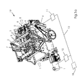
- FIG. 3 a cutting device 20 according to the invention is shown, wherein in FIG. 3 For better clarity, only the head-side transport device is shown and the control units and the connections have been omitted.
- the cutting device 20 has an upper knife bridge 25, which is offset by a drive motor 21 in strokes.
- the upper knife bridge 25 extends through all the cutting stations, in the present example, there are three: the station 26 for the leading edge trimming, the station 27 for the head and Briefberough and another processing station 28 for special punches or for Depanelization.
- the station 26 for the leading edge trimming
- the station 27 for the head and
- Another processing station 28 for special punches or for Depanelization.
- At the upper knife bridge corresponding upper blade 29, 30, 31, 32 are mounted, which are moved against lower blade 33 and thus perform the edge trim or special punches orsocitrennung the product 40.
- the product 40 is transported by a transport device 34 through the individual cutting stations 26, 27, 28 of the device 20.
- the transport device 34 has head-side 35, 36 and foot-side conveyor belt pairs 37, 38, between which the product 40 is clamped.
- the head-side conveyor belt pairs 35, 36 are driven by an independent drive motor 23 and the foot-side conveyor belt pairs by an independent drive motor 22nd
- the individual independent drives 21, 22, 23 are coupled to one another via their associated control units 47, 48, 49 via a connection 50 for the exchange of data and / or control signals. Furthermore, they may additionally be connected to the central machine controller 51. By way of this it is possible to act on the respective drives 22 and 23 with a defined movement profile and thus to accelerate and transport the product 40 individually on its head and foot.
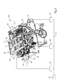
- FIG. 4 the essential components of the transport device 34 are shown.
- the transport direction of the products 40, 40 ', 40 " is represented by the arrows T.
- the transport device 34 extends through three cutting stations In the first station, the leading edge trimming is effected by means of the upper blade 29 and lower blade 33 Head andmodeberough by means of upper blades 31, 30 and lower blade 33.
- In the third station is a gravis means separating knife 32 and lower blade 33.
- the second or third station can also special punches are made by means of appropriate punching tools 41.
- the product is 40.
- the product 40 is transported to the next cutting station
- the products are transported by means of two pairs of conveyor belts 35, 36, 37, 38, which face each other in pairs and clamp the product non-positively on the top and bottom sides.
- the product 40 is accelerated by the transport device 34 within the device 20, transported in the correct position in the respective cutting station and then braked to a standstill. This process is repeated for further processing steps and finally for the transport of the product out of the device 20 to a device 20 downstream transport device, a processing device or display.
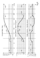
- FIG. 5 shows by way of example a possible movement profile of a pair of transport belts during an entire working cycle (0-360 °) of the cutting device. Shown in FIG. 5 in the upper diagram is the path of a cam in degrees of rotation, in the middle diagram the first derivative as normalized velocity (ds / dPhi) and in the lower diagram the second derivative as normalized acceleration (dv / dPhi), respectively over 0 ° - 360 ° ( x-axis), which correspond to one machine cycle. With 100, 105 respectively the bottom dead center of the upper knife bridge at 0 ° or 360 ° is designated. At this point, the cutting process is complete but the product is not yet released. As a result, the transport belt pair is not moving yet.
- the product is released and transport can begin. Consequently, at point 101, the cam path is still zero; as well as the speed.
- the acceleration of the Transport belt starts at point 101, as shown in the lower diagram of the FIG. 5 to recognize.
- the acceleration of the conveyor belt takes place to the point 102 (about 164 °).
- the cam has covered a distance of about 130 degrees rotation angle and the conveyor belts move at a standardized speed of 3.2. Up to point 103 there is no further acceleration, so that the conveyor belts continue to move at the same speed.
- the product is placed in the next cutting station or a new product is placed in the first cutting station. As a result, the conveyor belts are braked accordingly to a standstill. From point 104 to 105 the ribbons stop. It takes place in the respective cutting station, the pressing of the product by means not shown pressing beam and the lowering of the upper blade bridge to the bottom dead center and thus the edge trim of the product 40th
Abstract
Description
- Die Erfindung betrifft eine Vorrichtung und ein Verfahren zum gleichzeitigen, dreiseitigen Beschnitt von Produkten gemäß dem Oberbegriff von Anspruch 1.
- Bei der Herstellung von Broschuren werden an Sammelheftern die zusammengetragenen und gehefteten Produkte in einer Vorrichtung zum dreiseitigen Beschnitt, etwa einem Trimmer, geschnitten. Dies erfolgt in den Schneidestationen für den Vorderkantenbeschnitt und den Kopf- bzw. Fußbeschnitt durch bewegte Obermesser gegen feststehende Untermesser oder Schneidleisten.
- Aus der
EP 1 152 310 A1 ist ein solcher Trimmer bekannt. Der Trimmer weist eine gemeinsame Obermesserbrücke auf, die über einen Servomotor in einer Hubbewegung betreibbar ist. An der Obermesserbrücke sind die Obermesser für den Vorderkantenbeschnitt und für den Kopf- und Fußbeschnitt befestigt. Der Vorderkantenbeschnitt erfolgt hierbei in einer ersten Schneidstation und der Kopf- und Fußbeschnitt in einer zweiten Schneidstation. Zum Transport der Produkte in die Schneidstationen und aus diesen heraus weist der Trimmer eine Transportvorrichtung für die Produkte auf. Die Durchführung des dreiseitigen Beschnitts erfolgt hierbei in einzelnen Schritten. Das Transportsystem transportiert das Produkt in die erste Schneidstation und bringt das Produkt positionsgenau zum Stillstand. Dann erfolgt der Vorderkantenbeschnitt. Anschließend wird das Produkt durch das Transportsystem in eine zweite Schneidestation transportiert und positionsgenau zum Stillstand gebracht. Dann erfolgt der Kopf- und Fußbeschnitt. Anschließend wird das dreiseitige beschnittene Produkt in die Auslage transportiert. Das aus derEP 1 152 310 A1 bekannte Transportsystem besteht aus kopf- und fußseitigen Bänderpaaren, zwischen denen das Produkt kraftschlüssig geklemmt wird. Die Bänderpaare werden hierbei über durchgehende Antriebswellen von einem unabhängigen Antrieb, beispielsweise einem Servomotor, angetrieben. - Zum Einstellen der Schneideinrichtung auf unterschiedliche Produktformate wird der Abstand der beiden Bänderpaare zueinander ebenfalls auf das jeweilige Produktformat eingestellt. Um das zu ermöglichen, sind verschiebbare formschlüssige Verbindungen zwischen Antriebswellen und Zahnriemenscheiben der Transportbänder vorgesehen. Die formschlüssigen Verbindungen sind als Polygonwellen oder Vielkeilwellen ausgebildet und unterliegen durch die Wechsellasten beim Beschleunigen und Bremsen der Produkte einem hohen Verschleiß. Dadurch können sie unbrauchbar werden und verursachen kostspielige Reparaturen. Auch die Transportbänder selbst unterliegen einem Verschleiß und müssen regelmäßig ausgewechselt werden. Das Wechseln der Transportbänder ist aufgrund der durchgehenden Wellen, welche beide Bänderpaare antreiben, mit einem hohen Arbeitsaufwand verbunden. Darüber hinaus ist auch der Einbau und Ausbau einer zusätzlichen Bearbeitungseinrichtung, z. B. einer Mittelschnitteinrichtung, mit einem hohen Arbeitsaufwand verbunden.
- Aufgabe der vorliegenden Erfindung ist es, eine Vorrichtung zu schaffen, die die Nachteile des Standes der Technik vermeidet und einen sicheren Transport der Produkte gewährleistet bei gleichzeitiger einfacher Anpassung der Vorrichtung auf unterschiedliche Produktformate.
- Gelöst wird diese Aufgabe durch eine Vorrichtung gemäß dem kennzeichnenden Teil von Anspruch 1.
- Vorteilhafte Weiterbildungen der Erfindung ergeben sich aus den Unteransprüchen sowie aus der Beschreibung der Ausführungsbeispiele und den zugehörigen Zeichnungen.
- Eine erfindungsgemäße Ausführungsform einer Vorrichtung zum gleichzeitigen dreiseitigen Beschnitt von Produkten weist mehrere Schneidstationen auf. Weiterhin weist die Vorrichtung eine gemeinsame Obermesserbrücke auf, die sich durch die Schneidstationen erstreckt. Die Obermesserbrücke ist über einen ersten Antrieb in einer Hubbewegung betreibbar. An der Obermesserbrücke sind wenigstens die Messer zum Vorderkantenbeschnitt sowie zum Kopf- und Fußbeschnitt befestigt. Die Produkte werden mittels einer Transporteinrichtung mit kopfseitigen und fußseitigen Transportriemenpaaren durch die Schneidstationen der Vorrichtung transportiert. Die Antriebe für die Hubeinrichtung und die Transporteinrichtung sind jeweils als eigenständige, voneinander unabhängige Antriebe ausgeführt und über Steuereinrichtungen miteinander verbunden. Der Antrieb für die kopf- und fußseitigigen Transportriemenpaare der Transporteinrichtung weist jeweils eigenständige, voneinander unabhängige, positionsgeregelte Antriebe für jedes der beiden Transportriemenpaare auf. Dadurch sind keine verschleißanfälligen, formschlüssigen, durchgehenden Verbindungen im Antriebsstrang erforderlich. Das Auswechseln der Transportriemen wird wesentlich vereinfacht; ebenso das Einbauen und Ausbauen zusätzlicher Bearbeitungseinrichtungen, wie beispielsweise für Nutzentrennung oder Sonderstanzungen.
- In einer vorteilhaften Ausgestaltung werden die Antriebe der kopf- und fußseitigen über die Steuereinheiten bzw. über eine zentrale Maschinensteuerung mit Bewegungsprofilen beaufschlagt. Hierbei können die Bewegungsprofile für die beiden Bänderpaare jeweils gleich oder unterschiedlich sein. Dadurch ist es möglich, den Transport des Produktes von Schneidstation zu Schneidstation so zu steuern, dass bewusst unterschiedliche Transportwege an der Kopf- und Fußseite des Produktes gewählt werden, um das gewünschte Schneidergebnis zu erzielen.
- Weitere vorteilhafte Ausführungen der Erfindung werden anhand der nachfolgenden Figuren dargestellt.
- Es zeigen im Einzelnen:
- Figur 1A
- eine Schneidevorrichtung mit Transportvorrichtung gemäß dem Stand der Technik
- Figur 1B
- eine Ansicht der Antriebe einer Vorrichtung gemäß
Figur 1A - Figur 2
- eine erfindungsgemäße Schneidevorrichtung
- Figur 3
- Teile der Transportvorrichtungen innerhalb einer erfindungsgemäßen Vorrichtung von
Figur 2 - Figur 4
- die Transportvorrichtung
- Figur 5
- ein Bewegungsprofil der Transporteinrichtung.
- Ein repräsentatives Beispiel für eine Schneidvorrichtung 19 zum Randbeschneiden mit getrennten Antriebsvorrichtungen gemäß dem Stand der Technik wird in
Fig. 1A gezeigt. Ein erster Antriebsmotor 1 realisiert die Bewegung der Obermesserbrücke 2, an welcher die Obermesser befestigt sind. Die Produktlaufrichtung ist durch Pfeile T gekennzeichnet. Ein zweiter Antriebsmotor 4 treibt über eine erste und zweite jeweils durchgehende Antriebswelle 5, 6 die Bänder 7, 8 des Transportsystems 9 an. Für beide Antriebsmotoren 1, 4 sind Steuereinheiten 10, 11 vorgesehen, welche mittels einer Verbindung zum Austausch von Daten und / oder Steuersignalen 12 miteinander kommunizieren können. Weiterhin kann die Verbindung 12 auch zu einer zentralen Maschinensteuereinheit 18 führen. - Die wesentlichen Elemente der die zwei Bewegungsabläufe realisierenden Antriebe sind in der
Fig. 1B erkennbar. Der erste Antriebsmotor 1 realisiert vermittels des Zahnriemens 15, der Zahnriemenscheibe 16 und des Getriebes 17 die vertikale unharmonische Oszillationsbewegung der Obermesserbrücke 2. Die Obermesser 3 werden während des Schneidevorgangs gegen Untermesser 13 gedrückt. Der zweite Antriebsmotor 4 treibt vermittels eines mechanischen Getriebes 14 die Wellen 5, 6, so dass die Bänder 7, 8 des Transportsystems bewegt werde. Die Pfeile T geben die Produktlaufrichtung an. - In den
Figuren 2 und3 ist eine erfindungsgemäße Schneideeinrichtung 20 dargestellt, wobei inFigur 3 der besseren Übersichtlichkeit wegen nur die kopfseitige Transportvorrichtung dargestellt ist und die Steuereinheiten sowie die Verbindungen weggelassen wurden. Die Schneideeinrichtung 20 weist eine Obermesserbrücke 25 auf, die durch einen Antriebsmotor 21 in Hubbewegungen versetzt wird. Die Obermesserbrücke 25 erstreckt sich durch alle Schneidstationen, im vorliegenden Beispiel sind es drei: die Station 26 für den Vorderkantenbeschnitt, die Station 27 für den Kopf- und Fußbeschnitt und eine weitere Bearbeitungsstation 28 für spezielle Stanzungen oder für die Nutzentrennung. An der Obermesserbrücke sind entsprechende Obermesser 29, 30, 31, 32 angebracht, die gegen Untermesser 33 bewegt werden und so den Randbeschnitt oder Sonderstanzungen bzw. Nutzentrennung des Produktes 40 durchführen. Das Produkt 40 wird von einer Transporteinrichtung 34 durch die einzelnen Schneidstationen 26, 27, 28 der Vorrichtung 20 transportiert. Die Transporteinrichtung 34 weist hierzu kopfseitige 35, 36 und fußseitige Transportriemenpaare 37, 38 auf, zwischen denen das Produkt 40 geklemmt wird. Angetrieben werden die kopfseitigen Transportriemenpaare 35, 36 durch einen unabhängigen Antriebsmotor 23 und die fußseitigen Transportriemenpaare durch einen unabhängigen Antriebsmotor 22. - Die einzelnen unabhängigen Antriebe 21, 22, 23 sind über ihre zugehörigen Steuereinheiten 47, 48, 49 über eine Verbindung 50 zum Austausch von Daten und / oder Steuersignalen miteinander gekoppelt. Des Weiteren können sie zusätzlich noch mit der zentralen Maschinensteuerung 51 verbunden sein. Hierüber ist es möglich, die jeweiligen Antriebe 22 und 23 mit einem definierten Bewegungsprofil zu beaufschlagen und so das Produkt 40 individuell an seiner Kopf- und Fußseite zu beschleunigen und zu transportieren.
- In
Figur 4 sind die wesentlichen Bauteile der Transportvorrichtung 34 dargestellt. Die Transportrichtung der Produkte 40, 40', 40" ist durch die Pfeile T dargestellt. Die Transportvorrichtung 34 erstreckt sich im vorliegenden Ausführungsbeispiel durch drei Schneidestationen. In der ersten Station erfolgt der Vorderkantenbeschnitt mittels Obermesser 29 und Untermesser 33. In der zweiten Station erfolgt der Kopf- und Fußbeschnitt mittels Obermessern 31, 30 und Untermesser 33. In der dritten Station erfolgt eine Nutzentrennung mittels Trennmesser 32 und Untermesser 33. In der zweiten oder dritten Station können zusätzlich auch Sonderstanzungen mittels entsprechender Stanzwerkzeuge 41 vorgenommen werden. Während der Schneidvorgänge steht das Produkt 40 still. Nach Beendigung des jeweiligen Schneidvorgangs wird das Produkt 40 zur nächsten Schneidstation transportiert. Der Transport der Produkte erfolgt mittels zweier Transportriemenpaare 35, 36, 37, 38, die sich paarweise gegenüberstehen und das Produkt jeweils an der Kopf- und Fußseite kraftschlüssig klemmen. - Die kopf- 35, 36 und fußseitigen 37, 38 Transportriemenpaare werden jeweils durch unabhängige Antriebsmotoren 22, 23 mit den zugehörigen Komponenten der Antriebsstränge 42, 43 angetrieben. Jeder der beiden Antriebsstränge 42, 43 wird jeweils gebildet aus den Komponenten:
- Zahnriemenscheibe 60, 61 auf der Motorwelle (wobei in
Fig. 4 die Zahnriemenscheibe 61 verdeckt ist); - Zahnriemenscheibe 63, 64 zum Antrieb der Welle 65, 66 für den oberen Riemen 35, 37;
- Zahnriemenscheibe 67, 68 zum Antrieb der Welle 69, 70 für den unteren Riemen 36, 38 (wobei in
Fig. 4 die Welle 70 verdeckt ist); - Zahnriemenscheibe 71, 72 als Umlenk- und Spanneinrichtung (wobei die Zahnriemenscheibe 71 in
Fig. 4 verdeckt ist); - Doppelseitig verzahnte Zahnriemen 73, 74
- Das Produkt 40 wird von der Transportvorrichtung 34 innerhalb der Vorrichtung 20 beschleunigt, positionsgerecht in die jeweilige Schneidstation transportiert und dann bis zum Stillstand abgebremst. Dieser Vorgang wiederholt sich für weitere Bearbeitungsschritte und schließlich zum Transport des Produktes aus der Vorrichtung 20 heraus zu einer der Vorrichtung 20 nachgelagerten Transportvorrichtung, einer Bearbeitungsvorrichtung oder Auslage.
-
Figur 5 zeigt beispielhaft ein mögliches Bewegungsprofil eines Transportriemenpaares während eines gesamten Arbeitstaktes (0 - 360°) der Schneidvorrichtung. Dargestellt inFigur 5 ist im oberen Diagramm der Weg einer Kurvenscheibe in Grad Drehwinkel, im mittleren Diagramm die erste Ableitung als normierte Geschwindigkeit (ds/dPhi) und im unteren Diagramm die zweite Ableitung als normierte Beschleunigung (dv/dPhi), jeweils über 0° - 360° (x-Achse), die einem Maschinentakt entsprechen. Mit 100, 105 ist jeweils der untere Totpunkt der Obermesserbrücke bei 0° bzw. 360° bezeichnet. An diesem Punkt ist der Schneidvorgang abgeschlossen aber das Produkt noch nicht frei. Demzufolge bewegt sich das Transportriemenpaar noch nicht. Beim Punkt 101 ist das Produkt freigegeben und der Transport kann beginnen. Folglich ist am Punkt 101 der Weg der Kurvenscheibe noch Null; ebenso die Geschwindigkeit. Die Beschleunigung der Transportriemen beginnt am Punkt 101, wie aus dem unteren Diagramm derFigur 5 zu erkennen. Die Beschleunigung der Transportriemen erfolgt bis zum Punkt 102 (etwa 164°). Die Kurvenscheibe hat bis hier einen Weg von etwa 130 Grad Drehwinkel zurückgelegt und die Transportriemen bewegen sich mit einer normierten Geschwindigkeit von 3,2. Bis zum Punkt 103 erfolgt keine weitere Beschleunigung, so dass sich die Transportriemen mit gleicher Geschwindigkeit weiter bewegen. Von Punkt 103 bis 104 erfolgt die Anlage des Produktes in der nächsten Schneidestation bzw. die Anlage eines neuen Produktes in der ersten Schneidestation. Demzufolge werden die Transportriemen entsprechend abgebremst bis zum Stillstand. Von Punkt 104 bis 105 stehen die Bänder still. Es erfolgt in der jeweiligen Schneidestation das Abpressen des Produktes mittels nicht näher dargestellter Pressbalken und die Absenkung der Obermesserbrücke bis zum unteren Totpunkt und damit der Randbeschnitt des Produktes 40. -
1 Antriebsmotor für Obermesserbrücke 2 Obermesserbrücke 3 Obermesser für Kopf- und Fußbeschnitt 4 Antriebsmotor für Transporteinrichtung 5 Antriebswelle 6 Antriebswelle 7 obere Transportbänder 8 untere Transportbänder 9 Transportsystem 10 Steuereinheit 11 Steuereinheit 12 Verbindung zum Austausch von Daten und / oder Steuersignalen 13 Untermesser 14 Getriebe 15 Zahnriemen 16 Zahnriemenscheibe 17 Getriebe 18 zentrale Maschinensteuerung 19 Schneidevorrichtung gemäß Stand der Technik 20 erfindungsgemäße Schneideeinrichtung 21 Antriebsmotor für Obermesserbrücke 22 Antriebsmotor für fußseitiges Transportbänderpaar 23 Antriebsmotor für kopfseitiges Transportbänderpaar 25 Obermesserbrücke 26 Schneidstation für Vorderkantenbeschnitt 27 Schneidstation für Kopf- und Fußbeschnitt 28 weitere Bearbeitungsstation 29 Obermesser für Vorderkantenbeschnitt 30 Obermesser für Fußbeschnitt 31 Obermesser für Kopfbeschnitt 32 Obermesser für Nutzentrennung 33 Untermesser 34 Transporteinrichtung 35 oberer kopfseitiger Transportriemen 36 unterer kopfseitiger Transportriemen 37 oberer fußseitiger Transportriemen 38 unterer fußseitiger Transportriemen 40, 40', 40" Produkt 41 Stanzwerkzeug 42 kopfseitiger Antriebsstrang 43 fußseitiger Antriebsstrang 47 Steuereinheit 48 Steuereinheit 49 Steuereinheit 50 Verbindung zum Austausch von Daten und / oder Steuersignalen 51 zentrale Maschinensteuerung 60 Zahnriemenscheibe auf der Motorwelle 61 Zahnriemenscheibe auf der Motorwelle 63 Zahnriemenscheibe 64 Zahnriemenscheibe 65 Welle 66 Welle 67 Zahnriemenscheibe 68 Zahnriemenscheibe 69 Welle 70 Welle 71 Zahnriemenscheibe 72 Zahnriemenscheibe 73 Zahnriemen 74 Zahnriemen 100 Punkt eines Bewegungsprofils 101 Punkt eines Bewegungsprofils 102 Punkt eines Bewegungsprofils 103 Punkt eines Bewegungsprofils 104 Punkt eines Bewegungsprofils 105 Punkt eines Bewegungsprofils T Transportrichtung
Claims (5)
- Vorrichtung (20) zum gleichzeitigen, dreiseitigen Beschnitt von Produkten (40) in mehreren Schneidstationen (26, 27, 28), mit einer gemeinsamen Obermesserbrücke (25), die in einer Hubbewegung betreibbar ist, wobei an der Obermesserbrücke wenigstens Messer zum Vorderkantenbeschnitt (29) sowie Kopf- und Fußbeschnitt (30, 31) der Produkte (40) anbringbar sind, mit einem ersten, die Obermesserbrücke (25) antreibenden Antrieb (21) sowie mit einer Transporteinrichtung (34) mit kopfseitigen und fußseitigen Transportriemenpaaren (35, 36, 37, 38) zum Transportieren der Produkte (40) durch die Schneidstationen (26, 27, 28) der Vorrichtung (20), mit einem zweiten, die Transporteinrichtung antreibenden Antrieb (22, 23), wobei der erste (21) und zweite (22, 23) Antrieb als eigenständige, voneinander unabhängige Antriebe ausgeführt sind, die über Steuereinheiten (47, 48, 49, 51) miteinander verbunden sind,
dadurch gekennzeichnet,
dass die kopfseitigen und fußseitigen Transportriemenpaare der Transporteinrichtung jeweils durch eigenständige voneinander unabhängige, positionsgeregelte Antriebe angetrieben werden. - Vorrichtung nach Anspruch 1 ,
dadurch gekennzeichnet,
dass die Antriebe (22, 23) der kopf- und fußseitigen Transportriemenpaare über die Steuereinheiten (48, 49) mit einem Bewegungsprofil beaufschlagt werden. - Vorrichtung nach Anspruch 2 ,
dadurch gekennzeichnet,
dass das Bewegungsprofil für die Antriebe der kopf- und fußseitigen Transportriemen jeweils gleich ist. - Vorrichtung nach Anspruch 2 ,
dadurch gekennzeichnet,
dass das Bewegungsprofil für die Antriebe der kopf- und fußseitigen Transportriemen jeweils unterschiedlich ist. - Vorrichtung nach einem der vorhergehenden Ansprüche ,
dadurch gekennzeichnet,
dass die Antriebe (22, 23) der kopf- und fußseitigen Transportriemenpaare mit einer zentralen Maschinensteuerung (51) verbunden sind.
Applications Claiming Priority (1)
| Application Number | Priority Date | Filing Date | Title |
|---|---|---|---|
| DE201210005462 DE102012005462A1 (de) | 2012-03-20 | 2012-03-20 | Schneidevorrichtung |
Publications (2)
| Publication Number | Publication Date |
|---|---|
| EP2641709A1 true EP2641709A1 (de) | 2013-09-25 |
| EP2641709B1 EP2641709B1 (de) | 2018-12-12 |
Family
ID=47790058
Family Applications (1)
| Application Number | Title | Priority Date | Filing Date |
|---|---|---|---|
| EP13157345.3A Not-in-force EP2641709B1 (de) | 2012-03-20 | 2013-03-01 | Schneidevorrichtung |
Country Status (5)
| Country | Link |
|---|---|
| US (1) | US10005638B2 (de) |
| EP (1) | EP2641709B1 (de) |
| JP (1) | JP6161351B2 (de) |
| CN (1) | CN103317544B (de) |
| DE (1) | DE102012005462A1 (de) |
Families Citing this family (5)
| Publication number | Priority date | Publication date | Assignee | Title |
|---|---|---|---|---|
| CN105562812B (zh) * | 2016-02-25 | 2018-03-02 | 江阴市北国包装设备有限公司 | 百叶端部间隔剪切机 |
| CN106698065A (zh) * | 2017-01-23 | 2017-05-24 | 苏州工业园区明扬彩色包装印刷有限公司 | 一种高效自动折纸轧形机 |
| CN107599004B (zh) * | 2017-10-17 | 2019-04-05 | 北京喜逢春雨农业科技发展有限公司 | 一种自动蔬菜切块装置 |
| EP3599103B1 (de) * | 2018-07-25 | 2020-10-14 | Müller Martini Holding AG | Sammelhefter für druckprodukte |
| CN114348749A (zh) * | 2020-10-13 | 2022-04-15 | 江苏闳业机械股份有限公司 | 一种不停机复合材料切割装置 |
Citations (2)
| Publication number | Priority date | Publication date | Assignee | Title |
|---|---|---|---|---|
| EP1152310A1 (de) | 2000-05-03 | 2001-11-07 | Heidelberger Druckmaschinen Aktiengesellschaft | Schneideeinrichtung |
| US20030145700A1 (en) * | 2002-02-07 | 2003-08-07 | Formax, Inc. | Conveyor system for slicer apparatus |
Family Cites Families (13)
| Publication number | Priority date | Publication date | Assignee | Title |
|---|---|---|---|---|
| US4776451A (en) * | 1986-09-26 | 1988-10-11 | Gaddis Donald L | Conveyor system for particulate material |
| JP3297164B2 (ja) * | 1993-02-12 | 2002-07-02 | 株式会社東芝 | 紙葉類搬送装置 |
| IT1278730B1 (it) * | 1995-07-12 | 1997-11-27 | Meschi Ind Grafica | Metodo e dispositivo per l'inizializzazione di un nastro di carta con fori di trascinamento laterali su una macchina di lavorazione e/o |
| US6721060B1 (en) * | 1996-05-01 | 2004-04-13 | Canon Finetech Inc. | Recording medium cutter image forming device using same |
| DE19911173C2 (de) * | 1999-03-12 | 2002-01-31 | Leica Microsystems | Mikrotom mit einem motorischen Zustellantrieb |
| CN2407907Y (zh) * | 1999-04-20 | 2000-11-29 | 无锡市北人协民印刷机械厂 | 一种分切机 |
| CN1226116C (zh) * | 1999-05-31 | 2005-11-09 | 比特林制造传播有限公司 | 切割机 |
| KR100412273B1 (ko) * | 2001-11-22 | 2003-12-31 | 미래산업 주식회사 | 인쇄회로기판 이송장치 |
| DE102005040799A1 (de) | 2005-08-29 | 2007-03-01 | Heidelberger Druckmaschinen Ag | Vorrichtung zum dreiseitigen Beschnitt von Produkten |
| US20070044616A1 (en) | 2005-08-29 | 2007-03-01 | Heidelberger Druckmaschinen Ag | Device for three-sided cropping of products |
| US7942398B1 (en) * | 2009-12-07 | 2011-05-17 | Pitney Bowes Inc. | Buffering apparatus for collations |
| US8584832B2 (en) * | 2009-12-07 | 2013-11-19 | Pitney Bowes Inc. | System and method for mailpiece skew correction |
| DE102010024771A1 (de) * | 2009-12-17 | 2011-06-22 | Heidelberger Druckmaschinen AG, 69115 | Schneide- und Stanzeinrichtung |
-
2012
- 2012-03-20 DE DE201210005462 patent/DE102012005462A1/de not_active Withdrawn
-
2013
- 2013-03-01 EP EP13157345.3A patent/EP2641709B1/de not_active Not-in-force
- 2013-03-20 US US13/847,829 patent/US10005638B2/en not_active Expired - Fee Related
- 2013-03-20 CN CN201310089455.0A patent/CN103317544B/zh not_active Expired - Fee Related
- 2013-03-21 JP JP2013058582A patent/JP6161351B2/ja not_active Expired - Fee Related
Patent Citations (2)
| Publication number | Priority date | Publication date | Assignee | Title |
|---|---|---|---|---|
| EP1152310A1 (de) | 2000-05-03 | 2001-11-07 | Heidelberger Druckmaschinen Aktiengesellschaft | Schneideeinrichtung |
| US20030145700A1 (en) * | 2002-02-07 | 2003-08-07 | Formax, Inc. | Conveyor system for slicer apparatus |
Non-Patent Citations (1)
| Title |
|---|
| GEORGE W. YOUNKIN: "Industrial Servo Control Systems", 31 December 2002, CRC PRESS, ISBN: 978-0-203-90945-4, article "I Basics of Industrial Servo Drives", pages: 1 - 9, XP002699814, DOI: 10.1201/9780203909454.pt1 * |
Also Published As
| Publication number | Publication date |
|---|---|
| EP2641709B1 (de) | 2018-12-12 |
| CN103317544B (zh) | 2017-04-12 |
| JP6161351B2 (ja) | 2017-07-12 |
| US20130247735A1 (en) | 2013-09-26 |
| DE102012005462A1 (de) | 2013-09-26 |
| US10005638B2 (en) | 2018-06-26 |
| CN103317544A (zh) | 2013-09-25 |
| JP2013193207A (ja) | 2013-09-30 |
Similar Documents
| Publication | Publication Date | Title |
|---|---|---|
| EP2641709B1 (de) | Schneidevorrichtung | |
| EP0401161B1 (de) | Verfahren und Anlage zur Bearbeitung von Glasscheiben | |
| EP1832399B1 (de) | Verfahren und Vorrichtung zum selbsttätigen Beschneiden von Druckerzeugnissen | |
| DE102009033649B4 (de) | Plattenaufteilanlage | |
| DE102012018024A1 (de) | Vorrichtung und Verfahren zum Nuten von Pappenzuschnitten | |
| EP2163376B1 (de) | Faltschachtelklebemaschine zur herstellung von faltschachteln aus zuschnitten | |
| EP1166977B1 (de) | Schneidmaschine zum selbsttätigen Beschneiden von Druckerzeugnissen | |
| EP1593485A1 (de) | Faltschachtelklebemaschine zur Herstellung von Faltschachteln aus Zuschnitten | |
| EP2641708B1 (de) | Schneidevorrichtung | |
| EP1152310B1 (de) | Schneideeinrichtung | |
| DE102004022209A1 (de) | Sammel- und Presseinrichtung einer Faltschachtelklebemaschine | |
| EP2764963B1 (de) | Vorrichtung zum dreiseitigen Beschnitt von Produkten | |
| DE102014006544A1 (de) | Verfahren und Vorrichtung eines Plattentrennautomaten | |
| DE3832215A1 (de) | Trennschneidvorrichtung | |
| EP1745895B1 (de) | Vorrichtung zum dreiseitigen Beschnitt von Produkten | |
| EP3141122B1 (de) | Vorrichtung und verfahren zur seitlichen beaufschlagung eines teigbandes | |
| EP0362833A2 (de) | Holzbearbeitungsmaschine, insbesondere Kehlmaschine | |
| EP1074324B1 (de) | Vorrichtung zur Dünnblech-Bearbeitung | |
| EP1674222B1 (de) | Vorschubraupe | |
| DE19547193A1 (de) | Verfahren und Vorrichtung zum Einschneiden eines Baumstammes | |
| EP0620072A1 (de) | Vorrichtung und Verfahren zur Dünnblechbearbeitung | |
| EP0988963A2 (de) | Verfahren zum kontinuierlichen Formgeben von flachen Zuschnitten in Schachteln | |
| DE2320053C3 (de) | Arbeitsverfahren und Vorrichtung zum Herstellen von Profilleisten | |
| DD283781A5 (de) | Vorschubeinrichtung zum zufuehren von blechtafeln zu einem stanzwerkzeug | |
| DE3124142A1 (de) | "vorschubeinrichtung fuer bogenbearbeitungsmaschinen" |
Legal Events
| Date | Code | Title | Description |
|---|---|---|---|
| PUAI | Public reference made under article 153(3) epc to a published international application that has entered the european phase |
Free format text: ORIGINAL CODE: 0009012 |
|
| AK | Designated contracting states |
Kind code of ref document: A1 Designated state(s): AL AT BE BG CH CY CZ DE DK EE ES FI FR GB GR HR HU IE IS IT LI LT LU LV MC MK MT NL NO PL PT RO RS SE SI SK SM TR |
|
| AX | Request for extension of the european patent |
Extension state: BA ME |
|
| 17P | Request for examination filed |
Effective date: 20140325 |
|
| RBV | Designated contracting states (corrected) |
Designated state(s): AL AT BE BG CH CY CZ DE DK EE ES FI FR GB GR HR HU IE IS IT LI LT LU LV MC MK MT NL NO PL PT RO RS SE SI SK SM TR |
|
| RAP1 | Party data changed (applicant data changed or rights of an application transferred) |
Owner name: MUELLER MARTINI HOLDING AG |
|
| GRAP | Despatch of communication of intention to grant a patent |
Free format text: ORIGINAL CODE: EPIDOSNIGR1 |
|
| STAA | Information on the status of an ep patent application or granted ep patent |
Free format text: STATUS: GRANT OF PATENT IS INTENDED |
|
| RIC1 | Information provided on ipc code assigned before grant |
Ipc: B65G 15/10 20060101ALI20180601BHEP Ipc: B26D 7/01 20060101ALI20180601BHEP Ipc: B26D 7/00 20060101ALN20180601BHEP Ipc: B26D 5/00 20060101AFI20180601BHEP Ipc: B26D 7/32 20060101ALN20180601BHEP Ipc: B65H 35/00 20060101ALI20180601BHEP |
|
| INTG | Intention to grant announced |
Effective date: 20180706 |
|
| GRAS | Grant fee paid |
Free format text: ORIGINAL CODE: EPIDOSNIGR3 |
|
| GRAA | (expected) grant |
Free format text: ORIGINAL CODE: 0009210 |
|
| STAA | Information on the status of an ep patent application or granted ep patent |
Free format text: STATUS: THE PATENT HAS BEEN GRANTED |
|
| AK | Designated contracting states |
Kind code of ref document: B1 Designated state(s): AL AT BE BG CH CY CZ DE DK EE ES FI FR GB GR HR HU IE IS IT LI LT LU LV MC MK MT NL NO PL PT RO RS SE SI SK SM TR |
|
| REG | Reference to a national code |
Ref country code: GB Ref legal event code: FG4D Free format text: NOT ENGLISH |
|
| REG | Reference to a national code |
Ref country code: CH Ref legal event code: EP |
|
| REG | Reference to a national code |
Ref country code: AT Ref legal event code: REF Ref document number: 1075337 Country of ref document: AT Kind code of ref document: T Effective date: 20181215 |
|
| REG | Reference to a national code |
Ref country code: DE Ref legal event code: R096 Ref document number: 502013011784 Country of ref document: DE |
|
| REG | Reference to a national code |
Ref country code: IE Ref legal event code: FG4D Free format text: LANGUAGE OF EP DOCUMENT: GERMAN |
|
| REG | Reference to a national code |
Ref country code: NL Ref legal event code: MP Effective date: 20181212 |
|
| REG | Reference to a national code |
Ref country code: LT Ref legal event code: MG4D |
|
| PG25 | Lapsed in a contracting state [announced via postgrant information from national office to epo] |
Ref country code: LT Free format text: LAPSE BECAUSE OF FAILURE TO SUBMIT A TRANSLATION OF THE DESCRIPTION OR TO PAY THE FEE WITHIN THE PRESCRIBED TIME-LIMIT Effective date: 20181212 Ref country code: NO Free format text: LAPSE BECAUSE OF FAILURE TO SUBMIT A TRANSLATION OF THE DESCRIPTION OR TO PAY THE FEE WITHIN THE PRESCRIBED TIME-LIMIT Effective date: 20190312 Ref country code: HR Free format text: LAPSE BECAUSE OF FAILURE TO SUBMIT A TRANSLATION OF THE DESCRIPTION OR TO PAY THE FEE WITHIN THE PRESCRIBED TIME-LIMIT Effective date: 20181212 Ref country code: BG Free format text: LAPSE BECAUSE OF FAILURE TO SUBMIT A TRANSLATION OF THE DESCRIPTION OR TO PAY THE FEE WITHIN THE PRESCRIBED TIME-LIMIT Effective date: 20190312 Ref country code: ES Free format text: LAPSE BECAUSE OF FAILURE TO SUBMIT A TRANSLATION OF THE DESCRIPTION OR TO PAY THE FEE WITHIN THE PRESCRIBED TIME-LIMIT Effective date: 20181212 Ref country code: LV Free format text: LAPSE BECAUSE OF FAILURE TO SUBMIT A TRANSLATION OF THE DESCRIPTION OR TO PAY THE FEE WITHIN THE PRESCRIBED TIME-LIMIT Effective date: 20181212 Ref country code: FI Free format text: LAPSE BECAUSE OF FAILURE TO SUBMIT A TRANSLATION OF THE DESCRIPTION OR TO PAY THE FEE WITHIN THE PRESCRIBED TIME-LIMIT Effective date: 20181212 |
|
| PGFP | Annual fee paid to national office [announced via postgrant information from national office to epo] |
Ref country code: DE Payment date: 20190315 Year of fee payment: 7 Ref country code: GB Payment date: 20190322 Year of fee payment: 7 Ref country code: FR Payment date: 20190322 Year of fee payment: 7 |
|
| PG25 | Lapsed in a contracting state [announced via postgrant information from national office to epo] |
Ref country code: AL Free format text: LAPSE BECAUSE OF FAILURE TO SUBMIT A TRANSLATION OF THE DESCRIPTION OR TO PAY THE FEE WITHIN THE PRESCRIBED TIME-LIMIT Effective date: 20181212 Ref country code: SE Free format text: LAPSE BECAUSE OF FAILURE TO SUBMIT A TRANSLATION OF THE DESCRIPTION OR TO PAY THE FEE WITHIN THE PRESCRIBED TIME-LIMIT Effective date: 20181212 Ref country code: RS Free format text: LAPSE BECAUSE OF FAILURE TO SUBMIT A TRANSLATION OF THE DESCRIPTION OR TO PAY THE FEE WITHIN THE PRESCRIBED TIME-LIMIT Effective date: 20181212 Ref country code: GR Free format text: LAPSE BECAUSE OF FAILURE TO SUBMIT A TRANSLATION OF THE DESCRIPTION OR TO PAY THE FEE WITHIN THE PRESCRIBED TIME-LIMIT Effective date: 20190313 |
|
| PG25 | Lapsed in a contracting state [announced via postgrant information from national office to epo] |
Ref country code: NL Free format text: LAPSE BECAUSE OF FAILURE TO SUBMIT A TRANSLATION OF THE DESCRIPTION OR TO PAY THE FEE WITHIN THE PRESCRIBED TIME-LIMIT Effective date: 20181212 |
|
| PG25 | Lapsed in a contracting state [announced via postgrant information from national office to epo] |
Ref country code: CZ Free format text: LAPSE BECAUSE OF FAILURE TO SUBMIT A TRANSLATION OF THE DESCRIPTION OR TO PAY THE FEE WITHIN THE PRESCRIBED TIME-LIMIT Effective date: 20181212 Ref country code: IT Free format text: LAPSE BECAUSE OF FAILURE TO SUBMIT A TRANSLATION OF THE DESCRIPTION OR TO PAY THE FEE WITHIN THE PRESCRIBED TIME-LIMIT Effective date: 20181212 Ref country code: PT Free format text: LAPSE BECAUSE OF FAILURE TO SUBMIT A TRANSLATION OF THE DESCRIPTION OR TO PAY THE FEE WITHIN THE PRESCRIBED TIME-LIMIT Effective date: 20190412 Ref country code: PL Free format text: LAPSE BECAUSE OF FAILURE TO SUBMIT A TRANSLATION OF THE DESCRIPTION OR TO PAY THE FEE WITHIN THE PRESCRIBED TIME-LIMIT Effective date: 20181212 |
|
| PG25 | Lapsed in a contracting state [announced via postgrant information from national office to epo] |
Ref country code: SK Free format text: LAPSE BECAUSE OF FAILURE TO SUBMIT A TRANSLATION OF THE DESCRIPTION OR TO PAY THE FEE WITHIN THE PRESCRIBED TIME-LIMIT Effective date: 20181212 Ref country code: IS Free format text: LAPSE BECAUSE OF FAILURE TO SUBMIT A TRANSLATION OF THE DESCRIPTION OR TO PAY THE FEE WITHIN THE PRESCRIBED TIME-LIMIT Effective date: 20190412 Ref country code: RO Free format text: LAPSE BECAUSE OF FAILURE TO SUBMIT A TRANSLATION OF THE DESCRIPTION OR TO PAY THE FEE WITHIN THE PRESCRIBED TIME-LIMIT Effective date: 20181212 Ref country code: SM Free format text: LAPSE BECAUSE OF FAILURE TO SUBMIT A TRANSLATION OF THE DESCRIPTION OR TO PAY THE FEE WITHIN THE PRESCRIBED TIME-LIMIT Effective date: 20181212 Ref country code: EE Free format text: LAPSE BECAUSE OF FAILURE TO SUBMIT A TRANSLATION OF THE DESCRIPTION OR TO PAY THE FEE WITHIN THE PRESCRIBED TIME-LIMIT Effective date: 20181212 |
|
| REG | Reference to a national code |
Ref country code: DE Ref legal event code: R097 Ref document number: 502013011784 Country of ref document: DE |
|
| PGFP | Annual fee paid to national office [announced via postgrant information from national office to epo] |
Ref country code: CH Payment date: 20190621 Year of fee payment: 7 |
|
| PLBE | No opposition filed within time limit |
Free format text: ORIGINAL CODE: 0009261 |
|
| STAA | Information on the status of an ep patent application or granted ep patent |
Free format text: STATUS: NO OPPOSITION FILED WITHIN TIME LIMIT |
|
| PG25 | Lapsed in a contracting state [announced via postgrant information from national office to epo] |
Ref country code: DK Free format text: LAPSE BECAUSE OF FAILURE TO SUBMIT A TRANSLATION OF THE DESCRIPTION OR TO PAY THE FEE WITHIN THE PRESCRIBED TIME-LIMIT Effective date: 20181212 Ref country code: SI Free format text: LAPSE BECAUSE OF FAILURE TO SUBMIT A TRANSLATION OF THE DESCRIPTION OR TO PAY THE FEE WITHIN THE PRESCRIBED TIME-LIMIT Effective date: 20181212 Ref country code: MC Free format text: LAPSE BECAUSE OF FAILURE TO SUBMIT A TRANSLATION OF THE DESCRIPTION OR TO PAY THE FEE WITHIN THE PRESCRIBED TIME-LIMIT Effective date: 20181212 |
|
| 26N | No opposition filed |
Effective date: 20190913 |
|
| PG25 | Lapsed in a contracting state [announced via postgrant information from national office to epo] |
Ref country code: LU Free format text: LAPSE BECAUSE OF NON-PAYMENT OF DUE FEES Effective date: 20190301 |
|
| REG | Reference to a national code |
Ref country code: BE Ref legal event code: MM Effective date: 20190331 |
|
| PG25 | Lapsed in a contracting state [announced via postgrant information from national office to epo] |
Ref country code: IE Free format text: LAPSE BECAUSE OF NON-PAYMENT OF DUE FEES Effective date: 20190301 |
|
| PG25 | Lapsed in a contracting state [announced via postgrant information from national office to epo] |
Ref country code: BE Free format text: LAPSE BECAUSE OF NON-PAYMENT OF DUE FEES Effective date: 20190331 |
|
| PG25 | Lapsed in a contracting state [announced via postgrant information from national office to epo] |
Ref country code: TR Free format text: LAPSE BECAUSE OF FAILURE TO SUBMIT A TRANSLATION OF THE DESCRIPTION OR TO PAY THE FEE WITHIN THE PRESCRIBED TIME-LIMIT Effective date: 20181212 |
|
| PG25 | Lapsed in a contracting state [announced via postgrant information from national office to epo] |
Ref country code: MT Free format text: LAPSE BECAUSE OF FAILURE TO SUBMIT A TRANSLATION OF THE DESCRIPTION OR TO PAY THE FEE WITHIN THE PRESCRIBED TIME-LIMIT Effective date: 20181212 |
|
| REG | Reference to a national code |
Ref country code: AT Ref legal event code: MM01 Ref document number: 1075337 Country of ref document: AT Kind code of ref document: T Effective date: 20190301 |
|
| REG | Reference to a national code |
Ref country code: DE Ref legal event code: R119 Ref document number: 502013011784 Country of ref document: DE |
|
| REG | Reference to a national code |
Ref country code: CH Ref legal event code: PL |
|
| PG25 | Lapsed in a contracting state [announced via postgrant information from national office to epo] |
Ref country code: AT Free format text: LAPSE BECAUSE OF NON-PAYMENT OF DUE FEES Effective date: 20190301 |
|
| PG25 | Lapsed in a contracting state [announced via postgrant information from national office to epo] |
Ref country code: FR Free format text: LAPSE BECAUSE OF NON-PAYMENT OF DUE FEES Effective date: 20200331 Ref country code: CH Free format text: LAPSE BECAUSE OF NON-PAYMENT OF DUE FEES Effective date: 20200331 Ref country code: LI Free format text: LAPSE BECAUSE OF NON-PAYMENT OF DUE FEES Effective date: 20200331 Ref country code: DE Free format text: LAPSE BECAUSE OF NON-PAYMENT OF DUE FEES Effective date: 20201001 |
|
| GBPC | Gb: european patent ceased through non-payment of renewal fee |
Effective date: 20200301 |
|
| PG25 | Lapsed in a contracting state [announced via postgrant information from national office to epo] |
Ref country code: GB Free format text: LAPSE BECAUSE OF NON-PAYMENT OF DUE FEES Effective date: 20200301 |
|
| PG25 | Lapsed in a contracting state [announced via postgrant information from national office to epo] |
Ref country code: CY Free format text: LAPSE BECAUSE OF FAILURE TO SUBMIT A TRANSLATION OF THE DESCRIPTION OR TO PAY THE FEE WITHIN THE PRESCRIBED TIME-LIMIT Effective date: 20181212 |
|
| PG25 | Lapsed in a contracting state [announced via postgrant information from national office to epo] |
Ref country code: HU Free format text: LAPSE BECAUSE OF FAILURE TO SUBMIT A TRANSLATION OF THE DESCRIPTION OR TO PAY THE FEE WITHIN THE PRESCRIBED TIME-LIMIT; INVALID AB INITIO Effective date: 20130301 |
|
| PG25 | Lapsed in a contracting state [announced via postgrant information from national office to epo] |
Ref country code: MK Free format text: LAPSE BECAUSE OF FAILURE TO SUBMIT A TRANSLATION OF THE DESCRIPTION OR TO PAY THE FEE WITHIN THE PRESCRIBED TIME-LIMIT Effective date: 20181212 |