EP2764963B1 - Vorrichtung zum dreiseitigen Beschnitt von Produkten - Google Patents
Vorrichtung zum dreiseitigen Beschnitt von Produkten Download PDFInfo
- Publication number
- EP2764963B1 EP2764963B1 EP14152045.2A EP14152045A EP2764963B1 EP 2764963 B1 EP2764963 B1 EP 2764963B1 EP 14152045 A EP14152045 A EP 14152045A EP 2764963 B1 EP2764963 B1 EP 2764963B1
- Authority
- EP
- European Patent Office
- Prior art keywords
- movement
- drive
- product
- pushing
- trimming
- Prior art date
- Legal status (The legal status is an assumption and is not a legal conclusion. Google has not performed a legal analysis and makes no representation as to the accuracy of the status listed.)
- Active
Links
Images

Classifications
-
- B—PERFORMING OPERATIONS; TRANSPORTING
- B26—HAND CUTTING TOOLS; CUTTING; SEVERING
- B26D—CUTTING; DETAILS COMMON TO MACHINES FOR PERFORATING, PUNCHING, CUTTING-OUT, STAMPING-OUT OR SEVERING
- B26D5/00—Arrangements for operating and controlling machines or devices for cutting, cutting-out, stamping-out, punching, perforating, or severing by means other than cutting
- B26D5/08—Means for actuating the cutting member to effect the cut
-
- B—PERFORMING OPERATIONS; TRANSPORTING
- B26—HAND CUTTING TOOLS; CUTTING; SEVERING
- B26D—CUTTING; DETAILS COMMON TO MACHINES FOR PERFORATING, PUNCHING, CUTTING-OUT, STAMPING-OUT OR SEVERING
- B26D7/00—Details of apparatus for cutting, cutting-out, stamping-out, punching, perforating, or severing by means other than cutting
- B26D7/01—Means for holding or positioning work
- B26D7/015—Means for holding or positioning work for sheet material or piles of sheets
-
- B—PERFORMING OPERATIONS; TRANSPORTING
- B26—HAND CUTTING TOOLS; CUTTING; SEVERING
- B26D—CUTTING; DETAILS COMMON TO MACHINES FOR PERFORATING, PUNCHING, CUTTING-OUT, STAMPING-OUT OR SEVERING
- B26D7/00—Details of apparatus for cutting, cutting-out, stamping-out, punching, perforating, or severing by means other than cutting
- B26D7/06—Arrangements for feeding or delivering work of other than sheet, web, or filamentary form
- B26D7/0608—Arrangements for feeding or delivering work of other than sheet, web, or filamentary form by pushers
-
- B—PERFORMING OPERATIONS; TRANSPORTING
- B65—CONVEYING; PACKING; STORING; HANDLING THIN OR FILAMENTARY MATERIAL
- B65H—HANDLING THIN OR FILAMENTARY MATERIAL, e.g. SHEETS, WEBS, CABLES
- B65H35/00—Delivering articles from cutting or line-perforating machines; Article or web delivery apparatus incorporating cutting or line-perforating devices, e.g. adhesive tape dispensers
- B65H35/04—Delivering articles from cutting or line-perforating machines; Article or web delivery apparatus incorporating cutting or line-perforating devices, e.g. adhesive tape dispensers from or with transverse cutters or perforators
- B65H35/06—Delivering articles from cutting or line-perforating machines; Article or web delivery apparatus incorporating cutting or line-perforating devices, e.g. adhesive tape dispensers from or with transverse cutters or perforators from or with blade, e.g. shear-blade, cutters or perforators
-
- B—PERFORMING OPERATIONS; TRANSPORTING
- B65—CONVEYING; PACKING; STORING; HANDLING THIN OR FILAMENTARY MATERIAL
- B65H—HANDLING THIN OR FILAMENTARY MATERIAL, e.g. SHEETS, WEBS, CABLES
- B65H9/00—Registering, e.g. orientating, articles; Devices therefor
- B65H9/10—Pusher and like movable registers; Pusher or gripper devices which move articles into registered position
- B65H9/101—Pusher and like movable registers; Pusher or gripper devices which move articles into registered position acting on the edge of the article
-
- B—PERFORMING OPERATIONS; TRANSPORTING
- B26—HAND CUTTING TOOLS; CUTTING; SEVERING
- B26D—CUTTING; DETAILS COMMON TO MACHINES FOR PERFORATING, PUNCHING, CUTTING-OUT, STAMPING-OUT OR SEVERING
- B26D7/00—Details of apparatus for cutting, cutting-out, stamping-out, punching, perforating, or severing by means other than cutting
- B26D2007/0012—Details, accessories or auxiliary or special operations not otherwise provided for
- B26D2007/0081—Cutting on three sides, e.g. trilateral trimming
-
- B—PERFORMING OPERATIONS; TRANSPORTING
- B65—CONVEYING; PACKING; STORING; HANDLING THIN OR FILAMENTARY MATERIAL
- B65H—HANDLING THIN OR FILAMENTARY MATERIAL, e.g. SHEETS, WEBS, CABLES
- B65H2701/00—Handled material; Storage means
- B65H2701/10—Handled articles or webs
- B65H2701/19—Specific article or web
- B65H2701/1932—Signatures, folded printed matter, newspapers or parts thereof and books
Definitions
- the invention relates to a device for three-sided trimming of products, in particular brochures, according to the preamble of claim 1.
- the collected and stapled products are cut in saddle stitchers in a device for three-sided trimming, such as a trimmer. This is done in the cutting stations for the front cut and the head trimming or foot trimming by a moving upper knife against a fixed lower knife. Trimming the brochure is a particularly important step, since this opens the folded sheets on the side and has a significant influence on the appearance of the brochure. It is important that the brochures are cut precisely. The correct positioning of the brochures is ensured on the one hand by the trimmer feed. On the other hand, the product is transported against the front edge stops and trimmed laterally in order to precisely set the section width for the head trimming or foot trimming. It is known from the prior art that the mechanism for the lateral alignment (side thruster) is driven by the lifting movement of the upper knife carrier and is thus directly coupled to the movement sequence of the cutting movement. Such a trimmer is known.
- a trimmer is known in which the movement of the side pusher is decoupled from the movement sequence of the cutting movement.
- a separate drive is assigned to the side pusher, which can be controlled via a control independently of the lifting movement of the knife lifting device.
- such a three-sided trimming device comprises means for initiating and / or terminating the pushing movement of the alignment device, such that the time of initiation and / or the pushing duration of the pushing movement within the cycle time of the device is independent of the lifting movement of the lifting device.
- This decoupling of the cutting movement from the impact movement makes it possible to make better use of the total time available for trimming the product on three sides.
- a separate drive is assigned to the alignment device, the device advantageously comprising a control which controls the drive of the alignment device independently of the lifting movement of the lifting device.
- the alignment device in this case comprises at least one bumper, which is mounted in the knife block via a holder and guide rods.
- the knife block also has a threaded spindle with a spindle nut.
- the holder is connected to the spindle nut.
- the alignment device can be driven directly by a linear motor.
- the spindle and the spindle nut would be omitted.
- the holder would be mounted directly on the so-called rotor of the linear motor.
- the drive would have a motor and a toothed belt drive or a chain drive or a spur gear stage.
- the drive would have a motor which is arranged in a direct axial extension of the threaded spindle.
- FIG. 1 A representative example of a device for trilateral trimming of products is shown in Fig. 1 shown.
- a first drive motor 1 realizes the movement of the knife lifting device 2, to which the knives 3 are fastened. The direction of product travel is indicated by arrows.
- a second drive motor 4 drives the conveyor belts 7, 8 of the transport device 9 via a first and second drive shaft 5, 6.
- Control units 10, 11 are provided for both drive motors 1, 4, which can communicate with one another by means of a connection for exchanging data and / or control signals 12. Furthermore, the connection 12 can also lead to a machine control unit and to the control 42 of the alignment device 30.
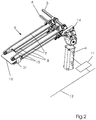
- the transport device is shown for itself.
- the drive motor 4 drives the drive shafts 5 and 6 and the conveyor belts 7, 8 of the transport device by means of a mechanical transmission 14.
- the control unit 11 and the connection for the exchange of data and / or control signals 12 can be seen.
- the products, coming from the delivery of a stapling machine from another transport system, not shown, are braked at the front edge stops 15.
- the electronic control by means of the control unit 11 makes it possible to gently bring the product 16 to the front edge stops 15 even at high speeds.
- the leading edge stops 15 are only provided in a first cutting position for the leading edge trimming.
- the product 16 is transported to the second cutting position by the transport device 9 without further alignment.
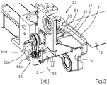
- FIG. 3 the lateral alignment device 30 is shown.
- the product 16 is aligned by the bumper strip 31, which detects the product 16 laterally.
- Figure 3 shows schematically the alignment device 30 according to the invention for the top side of the products 16.
- the bumper strip 31 of the alignment device 30 is mounted in the knife block 37 via the holder 51 and the guide rods 52.
- the threaded spindle 53 with the Spindle nut 54 is also mounted in the knife block 37.
- the holder 51 is connected to the spindle nut 54, so that when the threaded spindle 53 rotates, the spindle nut 54 is moved axially with the holder 51 and the bumper strip 31.
- the product 16 is aligned by this movement.
- the threaded spindle 53 is driven by means of a drive 35, for example consisting of a toothed belt drive 56a, 56b, 56c, a motor 55, preferably a servo motor or a stepper motor.
- the sequence of movements of the device is as follows: the machine control turns the motor during the format setting of the machine - from a fixed zero position - a certain number of revolutions and thus brings the push bar 31 into a certain position via the spindle drive, which corresponds to the required head trimming .
- the oscillating movement of the bumper strip 31 and thus the lifting movement for aligning the product 16 is achieved by rotating the motor to the left and to the right. Since the motor is controlled by the machine control, external influences are possible while the machine is running and also a separation of the side thruster movement from the knife movement. By storing different motion profiles for the motor in the machine control, it is possible to move the alignment device z. B. to adapt to different machine speeds.
- the front edge trimming of a product 16 is carried out simultaneously in a first cutting position and the head or foot trimming of a second product 16 is carried out in a second cutting position.
- the other components of the device according to the invention must be within the stroke of the knife lifting device 2 50 thus sometimes transport the second product 16 out of the device 50 from the second cutting position, transport the first product 16 from the first cutting position into the second cutting position and bring a new product 16 into the first cutting position.
- the transport device 9 must bring the product to the front edge stops 15 and also ensure that the product is aligned laterally before trimming.
- the conveyor belts 7, 8 of the transport device 9 also during the lateral Impact movement operated by the alignment device 30 so that the product 16 is driven against the front edge stops 15 until it is fully aligned. If the machine cycle of the device 50 is now increased, it is not enough to increase all other movements of the device to the same extent. Rather, the transport duration of the product 16 within the device 50 must not be less than a minimum transport duration, since otherwise the gentle and safe transport of the product 16 cannot be guaranteed.
- the time of the start of the shock movement and its duration can now be adapted in such a way that for the transport of the product, thanks to the separate drive of the push movement and the associated alignment control 42 16 the same amount of time remains within the device 50.
- the device has been described above in particular in connection with the three-sided trimming of brochures which are produced in a saddle stitcher. However, it is also conceivable to use the device for trimming other products on three sides. In addition, it is conceivable to provide a corresponding device which only carries out one or two trims on a product, or correspondingly more than three, for example in the so-called trio cut.
Landscapes
- Life Sciences & Earth Sciences (AREA)
- Forests & Forestry (AREA)
- Engineering & Computer Science (AREA)
- Mechanical Engineering (AREA)
- Details Of Cutting Devices (AREA)
- Folding Of Thin Sheet-Like Materials, Special Discharging Devices, And Others (AREA)
- Perforating, Stamping-Out Or Severing By Means Other Than Cutting (AREA)
Description
- Die Erfindung betrifft eine Vorrichtung zum dreiseitigen Beschnitt von Produkten, insbesondere Broschuren gemäß dem Oberbegriff des Anspruchs 1.
- Bei der Herstellung von Broschuren werden an Sammelheftern die zusammengetragenen und gehefteten Produkte in einer Vorrichtung zum dreiseitigen Beschnitt, etwa einem Trimmer geschnitten. Dies erfolgt in den Schneidstationen für den Vorderschnitt und den Kopfbeschnitt bzw. Fußbeschnitt durch ein bewegtes Obermesser gegen ein feststehendes Untermesser. Der Beschnitt der Broschur stellt dabei einen besonders wichtigen Schritt dar, da hierdurch die Falzbogen seitlich geöffnet werden und das äußere Erscheinungsbild der Broschur maßgeblich beeinflusst wird. Dazu ist es wichtig, dass die Broschuren positionsgenau geschnitten werden. Die korrekte Positionierung der Broschüren wird zum einen durch die Trimmerzuführung gewährleistet. Zum anderen wird das Produkt vor dem Beschnitt gegen Vorderkantenanschläge transportiert und seitlich ausgerichtet, um die Abschnittsbreite für den Kopfbeschnitt bzw. Fußbeschnitt exakt einzustellen. Aus dem Stand der Technik ist es bekannt, dass der Mechanismus für die seitliche Ausrichtung (Seitenstoßer) dabei durch die Hubbewegung des Obermesserträgers angetrieben wird und somit direkt an den Bewegungsablauf der Schneidbewegung gekoppelt ist. Ein derartiger Trimmer ist bekannt.
- Im Hinblick auf eine Optimierung der Bewegungsabläufe im Trimmer ist eine solche Vorrichtung nachteilig. Es wäre wünschenswert, den Seitenstoßer zu einem früheren Zeitpunkt vom Produkt weg zu bewegen, damit das Produkt bei Transportbeginn frei liegt und nicht durch den Seitenstoßer behindert wird.
- Aus der
US 2007/0028456 A1 ist ein Trimmer bekannt bei dem die Bewegung des Seitenstoßers von dem Bewegungsablauf der Schneidebewegung entkoppelt ist. Dem Seitenstoßer ist ein separater Antrieb zugeordnet, der über eine Steuerung unabhängig von der Hubbewegung der Messerhubeinrichtung ansteuerbar ist. - Wie bereits erwähnt, ist es weiterhin notwendig den Seitenstoßer auf die genaue Abschnittsbereite für den Kopfbeschnitt bzw. Fußbeschnitt exakt einzustellen. Diese Einstellung wird bei den bekannten Sammelheftern durch Verstellmechanismen bewerkstelligt, die nur im Stillstand der Maschine und nur bei geöffnetem Schutz zu bedienen sind. Hierzu ist es aus der
EP 1 837 135 A1 bekannt den Seitenschieber von außerhalb der Verkleidung zugänglicher Betätigungsorgane zu verstellen. Bei der bekannten Vorrichtung ist es nachteilig, dass die Hubbewegung des Seitenstoßers durch die Messerbewegung eingeleitet wird und somit zeitlich an die Messerbewegung gekoppelt ist. - Es ist deshalb Aufgabe der vorliegenden Erfindung eine Vorrichtung zu schaffen, die über einen von außen gesteuerten Antrieb sowohl die Hubbewegung des Seitenstoßers unabhängig von der Messerbewegung realisiert, als auch eine Verstellung des Seitenstoßeres bei geschlossenem Schutz während des Maschinenlaufs ermöglicht.
- Diese Aufgabe wird mit einer Vorrichtung zum dreiseitigen Beschnitt mit den kennzeichnenden Merkmalen von Anspruch 1 gelöst. Weitere Merkmale ergeben sich aus den Unteransprüchen.
- Dementsprechend umfasst eine derartige Vorrichtung zum dreiseitigen Beschnitt Mittel zum Einleiten und / oder Beenden der Stoßbewegung der Ausrichtungseinrichtung, derart, dass der Zeitpunkt des Einleitens und / oder die Stoßdauer der Stoßbewegung innerhalb der Taktdauer der Vorrichtung unabhängig von der Hubbewegung der Hubeinrichtung ist. Durch diese Entkopplung der Schneidbewegung von der Stoßbewegung kann die insgesamt für den dreiseitigen Beschnitt des Produktes zur Verfügung stehende Zeit besser genutzt werden. Zudem ist eine Anpassung beispielsweise der Stoßdauer auf unterschiedliche Produkteigenschaften, wie dessen Gewicht oder Abmessungen, möglich.
- In einer vorteilhaften Ausgestaltung der erfinderischen Vorrichtung ist der Ausrichtungseinrichtung ein separater Antrieb zugeordnet, wobei vorteilhafterweise die Vorrichtung eine Steuerung umfasst, die den Antrieb der Ausrichtungseinrichtung unabhängig von der der Hubbewegung der Hubeinrichtung ansteuert. Dadurch entfällt das aufwendige Ableiten der Stoßbewegung von der Hubbewegung der Hubeinrichtung, etwa durch ein mechanisches Kurvengetriebe. Außerdem können in der Steuerung für den Antrieb der Ausrichtungseinrichtung produktabhängig optimierte elektronische Steuerungskurven hinterlegt werden. Die Ausrichtungseinrichtung umfasst hierbei mindestens eine Stoßleiste, die über einen Halter und Führungsstangen im Messerblock gelagert ist. Der Messerblock weist weiterhin eine Gewindespindel mit einer Spindelmutter auf. Der Halter ist mit der Spindelmutter verbunden. Durch Drehung der Gewindespindel über den Antrieb wird die Spindelmutter mit dem Halter und der Leiste axial bewegt. Durch diese Anordnung ist eine vorteilhafte, stufenlose Einstellung des Pendelhubs unabhängig von der Messerbewegung möglich.
- In einer alternativen Ausführung kann die Ausrichtungseinrichtung durch einen Linearmotor direkt angetrieben werden. Bei dieser Variante würden die Spindel und die Spindelmutter entfallen. Der Halter wäre direkt auf dem sogenannten Läufer des Linearmotors montiert.
- In weiteren vorteilhaften Ausgestaltungen würde der Antrieb einen Motor und einen Zahnriementrieb oder einen Kettentrieb oder eine Stirnradstufe aufweisen.
- In einer weiteren vorteilhaften Ausgestaltung würde der Antrieb einen Motor aufweisen, der in direkter axialer Verlängerung der Gewindespindel angeordnet ist.
- Bevorzugte Ausführungsformen der erfindungsgemäßen Vorrichtung werden im Folgenden unter Bezugnahme auf die Zeichnungen im Einzelnen näher beschrieben.
- Es zeigen in schematischer Darstellung
- Fig. 1
- eine Ansicht der Vorrichtung zum Randbeschneiden von Produkten,
- Fig. 2
- eine detaillierte Ansicht der Transporteinrichtung und
- Fig. 3
- eine detaillierte Ansicht der Ausrichtungseinrichtung
- Ein repräsentatives Beispiel für eine Vorrichtung zum dreiseitigen Beschnitt von Produkten wird in
Fig. 1 gezeigt. Ein erster Antriebsmotor 1 realisiert die Bewegung der Messerhubeinrichtung 2, an welcher die Messer 3 befestigt sind. Die Produktlaufrichtung ist durch Pfeile gekennzeichnet. Ein zweiter Antriebsmotor 4 treibt über eine erste und zweite Antriebswelle 5, 6 die Transportbänder 7, 8 der Transporteinrichtung 9 an. Für beide Antriebsmotoren 1, 4, sind Steuereinheiten 10, 11 vorgesehen, welche mittels einer Verbindung zum Austausch von Daten und / oder Steuersignalen 12 miteinander kommunizieren können. Weiterhin kann die Verbindung 12 auch zu einer Maschinensteuereinheit führen sowie zur Steuerung 42 der Ausrichtungseinrichtung 30. - In der
Fig. 2 ist die Transporteinrichtung für sich dargestellt. Der Antriebsmotor 4 treibt vermittels eines mechanischen Getriebes 14 die Antriebswellen 5 und 6 und die Transportbänder 7, 8 der Transporteinrichtung an. Weiterhin ist die Steuereinheit 11 und die Verbindung zum Austausch von Daten und / oder Steuersignalen 12 zu sehen. Die Produkte werden, von einem weiteren, nicht gezeigten Transportsystem aus der Auslage einer Heftmaschine kommend, an den Vorderkantenanschlägen 15 abgebremst. Durch die elektronische Steuerung vermittels der Steuereinheit 11 ist es möglich, das Produkt 16 auch bei hohen Geschwindigkeiten sanft an die Vorderkantenanschläge 15 heranzuführen. Typischerweise sind die Vorderkantenanschläge 15 nur in einer ersten Schneidposition für den Vorderkantenbeschnitt vorgesehen. Der Transport des Produktes 16 zur zweiten Schneidposition durch die Transporteinrichtung 9 erfolgt ohne weitere Ausrichtung. - In
Fig. 3 ist die seitliche Ausrichtungseinrichtung 30 dargestellt. Die Ausrichtung des Produkts 16 erfolgt durch die Stoßleiste 31, die das Produkt 16 seitlich erfasst. Je nach Ausführungsform kann es vorgesehen sein, lediglich auf einer Seite des Produktes 16 eine erfindungsgemäße Ausrichtungseinrichtung 30 vorzusehen. Eine bevorzugte Ausführungsform weist aber beidseitig des Produktes 16 jeweils eine Ausrichtungseinrichtung 30 auf. Diese können getrennt oder gemeinsam durch eine Steuerung 42 angesteuert werden.Figur 3 zeigt schematisch die erfindungsgemäße Ausrichtungseinrichtung 30 für die Kopfseite der Produkte 16.
Die Stoßleiste 31 der Ausrichtungseinrichtung 30 ist über den Halter 51 und den Führungsstangen 52 im Messerblock 37 gelagert. Die Gewindespindel 53 mit der Spindelmutter 54 ist ebenfalls im Messerblock 37 gelagert. Der Halter 51 ist mit der Spindelmutter 54 verbunden, so dass bei Drehung der Gewindespindel 53 die Spindelmutter 54 mit dem Halter 51 und der Stoßleiste 31 axial bewegt wird. Durch diese Bewegung wird das Produkt 16 ausgerichtet.
Die Gewindespindel 53 wird mittels eines Antriebs 35 beispielsweise bestehend aus einem Zahnriementrieb 56a, 56b, 56c, einem Motor 55, vorzugsweise einem Servomotor oder einem Schrittmotor, angetrieben.
Der Bewegungsablauf der Vorrichtung ist wie folgt: Durch die Maschinensteuerung dreht der Motor während der Formateinstellung der Maschine - von einer festgelegten Nullposition aus - eine bestimmte Anzahl von Umdrehungen und bringt damit über den Spindeltrieb die Stoßleiste 31 in eine bestimmte Position, die dem erforderlichen Kopfbeschnitt entspricht. Ausgehend von dieser Position wird im Maschinenlauf durch Links-Rechtsdrehung des Motors die oszillierende Bewegung der Stoßleiste 31 erreicht und damit die Hubbewegung zur Ausrichtung des Produktes 16.
Da der Motor über die Maschinensteuerung geregelt wird, ist eine Beeinflussung von außen während des Maschinenlaufs möglich und ebenfalls eine Trennung der Seitenstoßerbewegung von der Messerbewegung. Durch die Hinterlegung unterschiedlicher Bewegungsprofile für den Motor in der Maschinensteuerung ist es möglich, die Bewegung der Ausrichtungseinrichtung z. B. an unterschiedliche Maschinengeschwindigkeiten anzupassen. - Im laufenden Betrieb der erfindungsgemäßen Vorrichtung 50 wird gleichzeitig in einer ersten Schneidposition der Vorderkantenbeschnitt eines Produktes 16 durchgeführt sowie in einer zweiten Schneidposition der Kopf- bzw. Fußbeschnitt eines zweiten Produktes 16. Innerhalb des Taktes der Hubbewegung der Messerhubeinrichtung 2 müssen die übrigen Komponenten der erfindungsgemäßen Vorrichtung 50 also mitunter das zweite Produkt 16, aus der zweiten Schneidposition aus der Vorrichtung 50 heraustransportieren, das erste Produkt 16 aus der ersten Schneidposition in die zweite Schneidposition transportieren und ein neues Produkt 16 in die erste Schneidposition bringen. Dazu muss die Transporteinrichtung 9 das Produkt bis zu den Vorderkantenanschlägen 15 bringen und ebenfalls eine seitliche Ausrichtung des Produktes vor dem Beschnitt gewährleisten. Dazu werden die Transportbänder 7, 8 der Transporteinrichtung 9 auch während der seitlichen Stoßbewegung durch die Ausrichtungseinrichtung 30 betrieben, so dass das Produkt 16 gegen die Vorderkantenanschläge 15 getrieben wird bis es vollständig ausgerichtet ist. Wird nun der Maschinentakt der Vorrichtung 50 erhöht, ist es nicht damit getan, alle übrigen Bewegungen der Vorrichtung in gleichem Maße zu erhöhen. Vielmehr darf die Transportdauer des Produkts 16 innerhalb der Vorrichtung 50 eine Mindesttransportdauer nicht unterschreiten, da sonst der schonende und sichere Transport des Produkts 16 nicht gewährleistet werden kann. Um dennoch die Vorrichtung 50 mit höheren Produktionsgeschwindigkeiten und damit mit einem kürzeren Takt betreiben zu können, kann nun dank des gesonderten Antriebs der Stoßbewegung und der zugeordneten Ausrichtungssteuerung 42 der Zeitpunkt des Beginns der Stoßbewegung sowie dessen Dauer derart angepasst werden, dass für den Transport des Produkts 16 innerhalb der Vorrichtung 50 gleich viel Zeit bleibt.
- Bei der erfindungsgemäßen Vorrichtung ist es weiterhin möglich den Pendelhub stufenlos auf unterschiedliche Formate während des laufenden Maschinenbetriebs einzustellen.
- Die Vorrichtung wurde vorgehend insbesondere im Zusammenhang mit dem dreiseitigen Beschnitt von Broschuren, die in einem Sammelhefter erzeugt werden, beschrieben. Es ist aber ohne weiteres denkbar, die Vorrichtung auch zum dreiseitigen Beschneiden von anderen Produkten zu verwenden. Außerdem ist es denkbar, eine entsprechende Vorrichtung vorzusehen, die lediglich eine oder zwei Beschnitte an einem Produkt vornimmt, oder entsprechend mehr als drei, etwa beim so genannten Trioschnitt.
Bezugszeichenliste 1 Antriebsmotor für Messer 2 Messerhubeinrichtung 3 Messer 4 Antriebsmotor für Transporteinrichtung 5 Antriebswelle 6 Antriebswelle 7 Obere Transportbänder 8 Untere Transportbänder 9 Transporteinrichtung 10 Steuereinheit 11 Steuereinheit 12 Verbindung zum Austausch von Daten und / oder Steuersignalen 14 mechanisches Getriebe 15 Vorderkantenanschlag 16 Produkt 30 seitliche Ausrichtungseinrichtung 31 Stoßleiste 35 Antrieb 37 Messerblock 42 Ausrichtungssteuerung 50 Vorrichtung 51 Halter 52 Führungsstange 53 Gewindespindel 54 Spindelmutter 55 Motor 56a 
Zahnriementrieb 56b 56c
Claims (8)
- Vorrichtung zum dreiseitigen Beschnitt von Produkten (16) mit einer Messerhubeinrichtung (2), die in einer Hubbewegung betreibbar ausgestaltet ist, wobei die Hubbewegung einen Maschinentakt der Vorrichtung (50) bestimmt, wobei an der Hubeinrichtung (2) wenigstens Messer (3) zum Kopfbeschnitt, Fussbeschnitt und Vorderkantenbeschnitt der Produkte (16) anbringbar sind, und wobei die Vorrichtung eine wenigstens einseitig bewegliche seitliche Ausrichtungseinrichtung (30) zur Ausführung einer Stossbewegung gegen das Produkt (16) aufweist, vermittels der das Produkt (16) in eine Schneidposition bringbar ist, wobei die Vorrichtung Mittel (35, 42) zum Einleiten und / oder Beenden der Stossbewegung der Ausrichtungseinrichtung (30) umfasst, derart, dass der Zeitpunkt des Einleitens und / oder die Stossdauer der Stossbewegung innerhalb der Taktdauer der Vorrichtung (50) unabhängig von der Hubbewegung der Messerhubeinrichtung (2) ist, wobei die Ausrichtungseinrichtung (30) mindestens eine Stossleiste (31) umfasst, welche in Wirkverbindung steht mit einem Halter (51) und mit Führungsstangen (52) wobei die Stossleiste (31), der Halter (51) und die Führungsstangen (52) Bestandteile eines Messerblocks (37) sind und in diesem gelagert sind, dadurch gekennzeichnet, dass der Messerblock (37) zusätzlich eine Gewindespindel (53) mit einer Spindelmutter (54) aufweist, welche im Messerblock (37) gelagert sind, der Halter (51) mit der Spindelmutter (54) verbunden ist und dass die Gewindespindel (53) mit einem Antrieb (35) verbunden ist, mit dem die Stossleiste (31) während einer Formateinstellung in eine Position bringbar ist, die dem erforderlichen Kopfbeschnitt entspricht und dass im Maschinenlauf von dieser Position aus mit dem Antrieb (35) eine Hubbewegung der Stossleiste (31) zur Ausrichtung des Produktes (16) erzeugbar ist.
- Vorrichtung nach Anspruch 1, dadurch gekennzeichnet, dass der Antrieb (35) einen Motor (55) und einen Zahnriemenantrieb (56a, 56b, 56c) aufweist
- Vorrichtung nach Anspruch 1, dadurch gekennzeichnet, dass der Antrieb (35) einen Motor (55) und einen Kettenantrieb oder eine Stirnradstufe aufweist.
- Vorrichtung nach Anspruch 1, dadurch gekennzeichnet, dass der Antrieb (35) als Motor (55) ausgebildet ist, der in direkter axialer Verlängerung der Gewindespindel (53) angeordnet ist.
- Vorrichtung nach einem der vorhergehenden Ansprüche, dadurch gekennzeichnet, dass der Antrieb (35) mit einer Ausrichtungssteuerung (42) verbunden ist.
- Verfahren zum Betrieb einer Vorrichtung zum dreiseitigen Beschnitt von Produkten (16) mit einer Messerhubeinrichtung (2), deren Hubbewegung einen Maschinentakt bestimmt und mit einer Ausrichtungseinrichtung (30) zur Ausführung einer Stossbewegung gegen das Produkt (16), mit der das Produkt (16) in eine Schneidposition gebracht wird, wobei das Einleiten und / oder Beenden der Stossbewegung der Ausrichtungseinrichtung (30) innerhalb der Taktdauer der Vorrichtung (50) unabhängig von der Hubbewegung der Messerhubeinrichtung (2) erfolgt, wobei eine Stossleiste (31) der Ausrichtungseinrichtung (30), die das Produkt seitlich erfasst, mit einem Halter (51) und mit Führungsstangen (52) in Wirkverbindung steht und wobei die Stossleiste (31), der Halter (51) und die Führungsstangen (52) Bestandteile eines Messerblocks (37) sind und in diesem gelagert sind dadurch gekennzeichnet, dass die Stossleiste (31) während einer Formateinstellung von einem Antrieb (35) über eine im Messerblock (37) gelagerte Gewindespindel (53) und eine mit dem Halter (51) verbundene Spindelmutter (54) in eine Position gebracht wird, die dem erforderlichen Kopfbeschnitt entspricht und dass im Maschinenlauf von dieser Position aus mit dem Antrieb (35) eine Hubbewegung der Stossleiste (31) zur Ausrichtung des Produktes (16) erzeugt wird.
- Verfahren nach Anspruch 6, dadurch gekennzeichnet, dass die Bewegung der Ausrichtungseinrichtung (30) durch Hinterlegung unterschiedlicher Bewegungsprofile für den Antrieb (35) in einer mit dem Antrieb (35) verbundenen Ausrichtungssteuerung (42) der Ausrichtungseinrichtung (30) angepasst wird.
- Verfahren nach Anspruch 7, dadurch gekennzeichnet, dass die Bewegung der Ausrichtungseinrichtung (30) mit den hinterlegten unterschiedlichen Bewegungsprofilen an unterschiedliche Maschinengeschwindigkeiten angepasst wird.
Applications Claiming Priority (1)
| Application Number | Priority Date | Filing Date | Title |
|---|---|---|---|
| DE102013002410.2A DE102013002410A1 (de) | 2013-02-11 | 2013-02-11 | Vorrichtung zum dreiseitigen Beschnitt von Produkten |
Publications (3)
| Publication Number | Publication Date |
|---|---|
| EP2764963A2 EP2764963A2 (de) | 2014-08-13 |
| EP2764963A3 EP2764963A3 (de) | 2015-03-04 |
| EP2764963B1 true EP2764963B1 (de) | 2020-04-01 |
Family
ID=49958355
Family Applications (1)
| Application Number | Title | Priority Date | Filing Date |
|---|---|---|---|
| EP14152045.2A Active EP2764963B1 (de) | 2013-02-11 | 2014-01-22 | Vorrichtung zum dreiseitigen Beschnitt von Produkten |
Country Status (3)
| Country | Link |
|---|---|
| EP (1) | EP2764963B1 (de) |
| CN (1) | CN103978512B (de) |
| DE (1) | DE102013002410A1 (de) |
Families Citing this family (3)
| Publication number | Priority date | Publication date | Assignee | Title |
|---|---|---|---|---|
| CN105984168A (zh) * | 2015-02-16 | 2016-10-05 | 苏州英派克印刷包装设备有限公司 | 一种包装盒切割装置 |
| DE102019120421A1 (de) * | 2019-07-29 | 2021-02-04 | Müller Martini Holding AG | Vorrichtung zum dreiseitigen Beschnitt der Kanten eines Druckprodukts |
| CN111958675A (zh) * | 2020-08-28 | 2020-11-20 | 李君� | 一种书本裁边机 |
Family Cites Families (10)
| Publication number | Priority date | Publication date | Assignee | Title |
|---|---|---|---|---|
| US4922773A (en) * | 1988-01-05 | 1990-05-08 | Itoh Iron Works Co., Ltd. | Three-side cutting apparatus |
| WO1991016181A1 (de) * | 1990-04-26 | 1991-10-31 | Am Wohlenberg Gmbh | Verfahren und vorrichtung zum einrichten eines dreischneiders |
| GB2307679B (en) * | 1995-11-30 | 1999-10-06 | Heidelberger Druckmasch Ag | Apparatus for forming a sheet pile e.g. in a delivery of a sheet-fed printing machine |
| EP1593467B1 (de) * | 2004-04-29 | 2007-08-22 | Senator Technology GmbH | Vorrichtung zum Handhaben eines Stapels |
| CN2782337Y (zh) * | 2005-03-17 | 2006-05-24 | 上海紫光机械有限公司 | 三面切书机两侧边裁切压紧装置 |
| DE102005033614A1 (de) * | 2005-07-19 | 2007-01-25 | Heidelberger Druckmaschinen Ag | Vorrichtung zum dreiseitigen Beschnitt von Produkten |
| US8656818B2 (en) | 2005-07-18 | 2014-02-25 | Heidelberger Druckmaschinen Ag | Device for three-sided trimming of products |
| DE102005040799A1 (de) * | 2005-08-29 | 2007-03-01 | Heidelberger Druckmaschinen Ag | Vorrichtung zum dreiseitigen Beschnitt von Produkten |
| DE102006013324A1 (de) | 2006-03-21 | 2007-09-27 | Hohner Maschinenbau Gmbh | Schneidvorrichtung für Druckbogenstapel |
| CN202241421U (zh) * | 2011-08-27 | 2012-05-30 | 杭州惠宝机电有限公司 | 三面切书器的书本理齐装置 |
-
2013
- 2013-02-11 DE DE102013002410.2A patent/DE102013002410A1/de not_active Withdrawn
-
2014
- 2014-01-22 EP EP14152045.2A patent/EP2764963B1/de active Active
- 2014-02-11 CN CN201410047359.4A patent/CN103978512B/zh active Active
Non-Patent Citations (1)
| Title |
|---|
| None * |
Also Published As
| Publication number | Publication date |
|---|---|
| EP2764963A3 (de) | 2015-03-04 |
| CN103978512B (zh) | 2018-05-22 |
| CN103978512A (zh) | 2014-08-13 |
| DE102013002410A1 (de) | 2014-08-14 |
| EP2764963A2 (de) | 2014-08-13 |
Similar Documents
| Publication | Publication Date | Title |
|---|---|---|
| DE19543860B4 (de) | Verfahren und Vorrichtung zum Formen geschlitzter und gefalzter Kartonformteile | |
| EP2258494B1 (de) | Biegevorrichtung für stabförmige Werkstücke | |
| DE102010017462B4 (de) | Drahtformungsvorrichtung mit radial angeordnetem Schneidwerkzeug | |
| EP1832399B2 (de) | Verfahren und Vorrichtung zum selbsttätigen Beschneiden von Druckerzeugnissen | |
| EP3515624A1 (de) | Verfahren; werkzeugmaschine und schlitzwerkzeug zum mehrhubig fortschreitenden schlitzen von plattenförmigen werkstücken | |
| DE3334263A1 (de) | Automatischer laengsschneider | |
| EP2764963B1 (de) | Vorrichtung zum dreiseitigen Beschnitt von Produkten | |
| EP1629992B1 (de) | Verfahren zum Heften von Druckprodukten und Heftmaschine | |
| EP2641709B1 (de) | Schneidevorrichtung | |
| EP1419898B1 (de) | Hefteinrichtung zur Herstellung von Druckerzeugnissen aus heftklammergebundenen Druckprodukten | |
| DE10021449A1 (de) | Schneideeinrichtung | |
| EP1759820B1 (de) | Vorrichtung zum dreiseitigen Beschnitt von Produkten | |
| EP2361785A1 (de) | Verfahren zum Heften von Druckprodukten mit einer Heftmaschine und Heftmaschine zum Durchführen des Verfahrens | |
| EP0234548A2 (de) | Werkzeugmaschine zum Ablängen und Lochen von Profilleisten | |
| EP2641708B1 (de) | Schneidevorrichtung | |
| EP1745895B1 (de) | Vorrichtung zum dreiseitigen Beschnitt von Produkten | |
| DE102016120139B4 (de) | Verfahren, Werkzeugmaschine und Schlitzwerkzeug zum mehrhubig fortschreitenden Schlitzen von plattenförmigen Werkstücken | |
| DE19756622B4 (de) | Doppelprofilschnittmaschine mit Längsverschiebung der Profile | |
| EP3369685A1 (de) | Vorrichtung zum transport länglicher stücke an eine aufnahmestelle und zu deren ablage an dieser | |
| EP2786823B1 (de) | Vorrichtung zum wahlweisen Schärfbearbeiten von Band- und Gattersägeblättern | |
| EP3025803B1 (de) | Antriebsvorrichtung für eine Werkzeugmaschine sowie Werkzeugmaschine mit einer derartigen Antriebsvorrichtung | |
| DE102019120421A1 (de) | Vorrichtung zum dreiseitigen Beschnitt der Kanten eines Druckprodukts | |
| DE69405964T2 (de) | Maschine für das Zusammensetzen von Pappschachteln | |
| DE102017202571A1 (de) | Heftkopf und Verfahren zum Heften von Druckprodukten | |
| EP2119568B1 (de) | Sammelhefter |
Legal Events
| Date | Code | Title | Description |
|---|---|---|---|
| PUAI | Public reference made under article 153(3) epc to a published international application that has entered the european phase |
Free format text: ORIGINAL CODE: 0009012 |
|
| 17P | Request for examination filed |
Effective date: 20140122 |
|
| AK | Designated contracting states |
Kind code of ref document: A2 Designated state(s): AL AT BE BG CH CY CZ DE DK EE ES FI FR GB GR HR HU IE IS IT LI LT LU LV MC MK MT NL NO PL PT RO RS SE SI SK SM TR |
|
| AX | Request for extension of the european patent |
Extension state: BA ME |
|
| RAP1 | Party data changed (applicant data changed or rights of an application transferred) |
Owner name: MUELLER MARTINI HOLDING AG |
|
| PUAL | Search report despatched |
Free format text: ORIGINAL CODE: 0009013 |
|
| AK | Designated contracting states |
Kind code of ref document: A3 Designated state(s): AL AT BE BG CH CY CZ DE DK EE ES FI FR GB GR HR HU IE IS IT LI LT LU LV MC MK MT NL NO PL PT RO RS SE SI SK SM TR |
|
| AX | Request for extension of the european patent |
Extension state: BA ME |
|
| RIC1 | Information provided on ipc code assigned before grant |
Ipc: B26D 7/06 20060101ALI20150128BHEP Ipc: B26D 5/00 20060101AFI20150128BHEP Ipc: B26D 5/08 20060101ALI20150128BHEP Ipc: B26D 7/00 20060101ALN20150128BHEP |
|
| R17P | Request for examination filed (corrected) |
Effective date: 20150702 |
|
| RBV | Designated contracting states (corrected) |
Designated state(s): AL AT BE BG CH CY CZ DE DK EE ES FI FR GB GR HR HU IE IS IT LI LT LU LV MC MK MT NL NO PL PT RO RS SE SI SK SM TR |
|
| RIC1 | Information provided on ipc code assigned before grant |
Ipc: B65H 35/06 20060101ALI20191008BHEP Ipc: B26D 5/00 20060101AFI20191008BHEP Ipc: B65H 9/10 20060101ALI20191008BHEP Ipc: B26D 5/08 20060101ALI20191008BHEP Ipc: B26D 7/00 20060101ALN20191008BHEP Ipc: B26D 7/01 20060101ALI20191008BHEP Ipc: B26D 7/06 20060101ALI20191008BHEP |
|
| GRAP | Despatch of communication of intention to grant a patent |
Free format text: ORIGINAL CODE: EPIDOSNIGR1 |
|
| STAA | Information on the status of an ep patent application or granted ep patent |
Free format text: STATUS: GRANT OF PATENT IS INTENDED |
|
| INTG | Intention to grant announced |
Effective date: 20191121 |
|
| GRAJ | Information related to disapproval of communication of intention to grant by the applicant or resumption of examination proceedings by the epo deleted |
Free format text: ORIGINAL CODE: EPIDOSDIGR1 |
|
| STAA | Information on the status of an ep patent application or granted ep patent |
Free format text: STATUS: REQUEST FOR EXAMINATION WAS MADE |
|
| GRAR | Information related to intention to grant a patent recorded |
Free format text: ORIGINAL CODE: EPIDOSNIGR71 |
|
| GRAS | Grant fee paid |
Free format text: ORIGINAL CODE: EPIDOSNIGR3 |
|
| STAA | Information on the status of an ep patent application or granted ep patent |
Free format text: STATUS: GRANT OF PATENT IS INTENDED |
|
| GRAJ | Information related to disapproval of communication of intention to grant by the applicant or resumption of examination proceedings by the epo deleted |
Free format text: ORIGINAL CODE: EPIDOSDIGR1 |
|
| GRAR | Information related to intention to grant a patent recorded |
Free format text: ORIGINAL CODE: EPIDOSNIGR71 |
|
| GRAS | Grant fee paid |
Free format text: ORIGINAL CODE: EPIDOSNIGR3 |
|
| GRAA | (expected) grant |
Free format text: ORIGINAL CODE: 0009210 |
|
| STAA | Information on the status of an ep patent application or granted ep patent |
Free format text: STATUS: THE PATENT HAS BEEN GRANTED |
|
| INTC | Intention to grant announced (deleted) | ||
| RIC1 | Information provided on ipc code assigned before grant |
Ipc: B26D 5/08 20060101ALI20200206BHEP Ipc: B65H 9/10 20060101ALI20200206BHEP Ipc: B26D 7/00 20060101ALN20200206BHEP Ipc: B26D 7/06 20060101ALI20200206BHEP Ipc: B26D 5/00 20060101AFI20200206BHEP Ipc: B65H 35/06 20060101ALI20200206BHEP Ipc: B26D 7/01 20060101ALI20200206BHEP |
|
| INTG | Intention to grant announced |
Effective date: 20200220 |
|
| AK | Designated contracting states |
Kind code of ref document: B1 Designated state(s): AL AT BE BG CH CY CZ DE DK EE ES FI FR GB GR HR HU IE IS IT LI LT LU LV MC MK MT NL NO PL PT RO RS SE SI SK SM TR |
|
| INTG | Intention to grant announced |
Effective date: 20200221 |
|
| REG | Reference to a national code |
Ref country code: GB Ref legal event code: FG4D Free format text: NOT ENGLISH |
|
| RIC1 | Information provided on ipc code assigned before grant |
Ipc: B26D 7/06 20060101ALI20200221BHEP Ipc: B65H 35/06 20060101ALI20200221BHEP Ipc: B26D 7/00 20060101ALN20200221BHEP Ipc: B65H 9/10 20060101ALI20200221BHEP Ipc: B26D 5/08 20060101ALI20200221BHEP Ipc: B26D 7/01 20060101ALI20200221BHEP Ipc: B26D 5/00 20060101AFI20200221BHEP |
|
| REG | Reference to a national code |
Ref country code: AT Ref legal event code: REF Ref document number: 1250787 Country of ref document: AT Kind code of ref document: T Effective date: 20200415 Ref country code: CH Ref legal event code: EP |
|
| REG | Reference to a national code |
Ref country code: DE Ref legal event code: R096 Ref document number: 502014013875 Country of ref document: DE |
|
| REG | Reference to a national code |
Ref country code: IE Ref legal event code: FG4D Free format text: LANGUAGE OF EP DOCUMENT: GERMAN |
|
| PG25 | Lapsed in a contracting state [announced via postgrant information from national office to epo] |
Ref country code: BG Free format text: LAPSE BECAUSE OF FAILURE TO SUBMIT A TRANSLATION OF THE DESCRIPTION OR TO PAY THE FEE WITHIN THE PRESCRIBED TIME-LIMIT Effective date: 20200701 |
|
| REG | Reference to a national code |
Ref country code: NL Ref legal event code: MP Effective date: 20200401 |
|
| REG | Reference to a national code |
Ref country code: LT Ref legal event code: MG4D |
|
| PG25 | Lapsed in a contracting state [announced via postgrant information from national office to epo] |
Ref country code: FI Free format text: LAPSE BECAUSE OF FAILURE TO SUBMIT A TRANSLATION OF THE DESCRIPTION OR TO PAY THE FEE WITHIN THE PRESCRIBED TIME-LIMIT Effective date: 20200401 Ref country code: NO Free format text: LAPSE BECAUSE OF FAILURE TO SUBMIT A TRANSLATION OF THE DESCRIPTION OR TO PAY THE FEE WITHIN THE PRESCRIBED TIME-LIMIT Effective date: 20200701 Ref country code: GR Free format text: LAPSE BECAUSE OF FAILURE TO SUBMIT A TRANSLATION OF THE DESCRIPTION OR TO PAY THE FEE WITHIN THE PRESCRIBED TIME-LIMIT Effective date: 20200702 Ref country code: SE Free format text: LAPSE BECAUSE OF FAILURE TO SUBMIT A TRANSLATION OF THE DESCRIPTION OR TO PAY THE FEE WITHIN THE PRESCRIBED TIME-LIMIT Effective date: 20200401 Ref country code: PT Free format text: LAPSE BECAUSE OF FAILURE TO SUBMIT A TRANSLATION OF THE DESCRIPTION OR TO PAY THE FEE WITHIN THE PRESCRIBED TIME-LIMIT Effective date: 20200817 Ref country code: LT Free format text: LAPSE BECAUSE OF FAILURE TO SUBMIT A TRANSLATION OF THE DESCRIPTION OR TO PAY THE FEE WITHIN THE PRESCRIBED TIME-LIMIT Effective date: 20200401 Ref country code: NL Free format text: LAPSE BECAUSE OF FAILURE TO SUBMIT A TRANSLATION OF THE DESCRIPTION OR TO PAY THE FEE WITHIN THE PRESCRIBED TIME-LIMIT Effective date: 20200401 Ref country code: IS Free format text: LAPSE BECAUSE OF FAILURE TO SUBMIT A TRANSLATION OF THE DESCRIPTION OR TO PAY THE FEE WITHIN THE PRESCRIBED TIME-LIMIT Effective date: 20200801 Ref country code: CZ Free format text: LAPSE BECAUSE OF FAILURE TO SUBMIT A TRANSLATION OF THE DESCRIPTION OR TO PAY THE FEE WITHIN THE PRESCRIBED TIME-LIMIT Effective date: 20200401 |
|
| PG25 | Lapsed in a contracting state [announced via postgrant information from national office to epo] |
Ref country code: RS Free format text: LAPSE BECAUSE OF FAILURE TO SUBMIT A TRANSLATION OF THE DESCRIPTION OR TO PAY THE FEE WITHIN THE PRESCRIBED TIME-LIMIT Effective date: 20200401 Ref country code: LV Free format text: LAPSE BECAUSE OF FAILURE TO SUBMIT A TRANSLATION OF THE DESCRIPTION OR TO PAY THE FEE WITHIN THE PRESCRIBED TIME-LIMIT Effective date: 20200401 Ref country code: HR Free format text: LAPSE BECAUSE OF FAILURE TO SUBMIT A TRANSLATION OF THE DESCRIPTION OR TO PAY THE FEE WITHIN THE PRESCRIBED TIME-LIMIT Effective date: 20200401 |
|
| PG25 | Lapsed in a contracting state [announced via postgrant information from national office to epo] |
Ref country code: AL Free format text: LAPSE BECAUSE OF FAILURE TO SUBMIT A TRANSLATION OF THE DESCRIPTION OR TO PAY THE FEE WITHIN THE PRESCRIBED TIME-LIMIT Effective date: 20200401 |
|
| REG | Reference to a national code |
Ref country code: DE Ref legal event code: R097 Ref document number: 502014013875 Country of ref document: DE |
|
| PG25 | Lapsed in a contracting state [announced via postgrant information from national office to epo] |
Ref country code: SM Free format text: LAPSE BECAUSE OF FAILURE TO SUBMIT A TRANSLATION OF THE DESCRIPTION OR TO PAY THE FEE WITHIN THE PRESCRIBED TIME-LIMIT Effective date: 20200401 Ref country code: IT Free format text: LAPSE BECAUSE OF FAILURE TO SUBMIT A TRANSLATION OF THE DESCRIPTION OR TO PAY THE FEE WITHIN THE PRESCRIBED TIME-LIMIT Effective date: 20200401 Ref country code: DK Free format text: LAPSE BECAUSE OF FAILURE TO SUBMIT A TRANSLATION OF THE DESCRIPTION OR TO PAY THE FEE WITHIN THE PRESCRIBED TIME-LIMIT Effective date: 20200401 Ref country code: RO Free format text: LAPSE BECAUSE OF FAILURE TO SUBMIT A TRANSLATION OF THE DESCRIPTION OR TO PAY THE FEE WITHIN THE PRESCRIBED TIME-LIMIT Effective date: 20200401 Ref country code: ES Free format text: LAPSE BECAUSE OF FAILURE TO SUBMIT A TRANSLATION OF THE DESCRIPTION OR TO PAY THE FEE WITHIN THE PRESCRIBED TIME-LIMIT Effective date: 20200401 Ref country code: EE Free format text: LAPSE BECAUSE OF FAILURE TO SUBMIT A TRANSLATION OF THE DESCRIPTION OR TO PAY THE FEE WITHIN THE PRESCRIBED TIME-LIMIT Effective date: 20200401 |
|
| PLBE | No opposition filed within time limit |
Free format text: ORIGINAL CODE: 0009261 |
|
| STAA | Information on the status of an ep patent application or granted ep patent |
Free format text: STATUS: NO OPPOSITION FILED WITHIN TIME LIMIT |
|
| PG25 | Lapsed in a contracting state [announced via postgrant information from national office to epo] |
Ref country code: PL Free format text: LAPSE BECAUSE OF FAILURE TO SUBMIT A TRANSLATION OF THE DESCRIPTION OR TO PAY THE FEE WITHIN THE PRESCRIBED TIME-LIMIT Effective date: 20200401 Ref country code: SK Free format text: LAPSE BECAUSE OF FAILURE TO SUBMIT A TRANSLATION OF THE DESCRIPTION OR TO PAY THE FEE WITHIN THE PRESCRIBED TIME-LIMIT Effective date: 20200401 |
|
| 26N | No opposition filed |
Effective date: 20210112 |
|
| PG25 | Lapsed in a contracting state [announced via postgrant information from national office to epo] |
Ref country code: SI Free format text: LAPSE BECAUSE OF FAILURE TO SUBMIT A TRANSLATION OF THE DESCRIPTION OR TO PAY THE FEE WITHIN THE PRESCRIBED TIME-LIMIT Effective date: 20200401 |
|
| PG25 | Lapsed in a contracting state [announced via postgrant information from national office to epo] |
Ref country code: MC Free format text: LAPSE BECAUSE OF FAILURE TO SUBMIT A TRANSLATION OF THE DESCRIPTION OR TO PAY THE FEE WITHIN THE PRESCRIBED TIME-LIMIT Effective date: 20200401 |
|
| REG | Reference to a national code |
Ref country code: CH Ref legal event code: PL |
|
| GBPC | Gb: european patent ceased through non-payment of renewal fee |
Effective date: 20210122 |
|
| PG25 | Lapsed in a contracting state [announced via postgrant information from national office to epo] |
Ref country code: LU Free format text: LAPSE BECAUSE OF NON-PAYMENT OF DUE FEES Effective date: 20210122 |
|
| REG | Reference to a national code |
Ref country code: BE Ref legal event code: MM Effective date: 20210131 |
|
| PG25 | Lapsed in a contracting state [announced via postgrant information from national office to epo] |
Ref country code: FR Free format text: LAPSE BECAUSE OF NON-PAYMENT OF DUE FEES Effective date: 20210131 |
|
| PG25 | Lapsed in a contracting state [announced via postgrant information from national office to epo] |
Ref country code: LI Free format text: LAPSE BECAUSE OF NON-PAYMENT OF DUE FEES Effective date: 20210131 Ref country code: GB Free format text: LAPSE BECAUSE OF NON-PAYMENT OF DUE FEES Effective date: 20210122 Ref country code: CH Free format text: LAPSE BECAUSE OF NON-PAYMENT OF DUE FEES Effective date: 20210131 |
|
| PG25 | Lapsed in a contracting state [announced via postgrant information from national office to epo] |
Ref country code: IE Free format text: LAPSE BECAUSE OF NON-PAYMENT OF DUE FEES Effective date: 20210122 |
|
| REG | Reference to a national code |
Ref country code: AT Ref legal event code: MM01 Ref document number: 1250787 Country of ref document: AT Kind code of ref document: T Effective date: 20210122 |
|
| PG25 | Lapsed in a contracting state [announced via postgrant information from national office to epo] |
Ref country code: AT Free format text: LAPSE BECAUSE OF NON-PAYMENT OF DUE FEES Effective date: 20210122 |
|
| PG25 | Lapsed in a contracting state [announced via postgrant information from national office to epo] |
Ref country code: BE Free format text: LAPSE BECAUSE OF NON-PAYMENT OF DUE FEES Effective date: 20210131 |
|
| PG25 | Lapsed in a contracting state [announced via postgrant information from national office to epo] |
Ref country code: HU Free format text: LAPSE BECAUSE OF FAILURE TO SUBMIT A TRANSLATION OF THE DESCRIPTION OR TO PAY THE FEE WITHIN THE PRESCRIBED TIME-LIMIT; INVALID AB INITIO Effective date: 20140122 |
|
| PG25 | Lapsed in a contracting state [announced via postgrant information from national office to epo] |
Ref country code: CY Free format text: LAPSE BECAUSE OF FAILURE TO SUBMIT A TRANSLATION OF THE DESCRIPTION OR TO PAY THE FEE WITHIN THE PRESCRIBED TIME-LIMIT Effective date: 20200401 |
|
| PG25 | Lapsed in a contracting state [announced via postgrant information from national office to epo] |
Ref country code: MK Free format text: LAPSE BECAUSE OF FAILURE TO SUBMIT A TRANSLATION OF THE DESCRIPTION OR TO PAY THE FEE WITHIN THE PRESCRIBED TIME-LIMIT Effective date: 20200401 |
|
| PG25 | Lapsed in a contracting state [announced via postgrant information from national office to epo] |
Ref country code: MT Free format text: LAPSE BECAUSE OF FAILURE TO SUBMIT A TRANSLATION OF THE DESCRIPTION OR TO PAY THE FEE WITHIN THE PRESCRIBED TIME-LIMIT Effective date: 20200401 |
|
| PGFP | Annual fee paid to national office [announced via postgrant information from national office to epo] |
Ref country code: DE Payment date: 20250130 Year of fee payment: 12 |