EP2641652B1 - Filtration avec contrôle de colmatage interne - Google Patents
Filtration avec contrôle de colmatage interne Download PDFInfo
- Publication number
- EP2641652B1 EP2641652B1 EP13172548.3A EP13172548A EP2641652B1 EP 2641652 B1 EP2641652 B1 EP 2641652B1 EP 13172548 A EP13172548 A EP 13172548A EP 2641652 B1 EP2641652 B1 EP 2641652B1
- Authority
- EP
- European Patent Office
- Prior art keywords
- permeate
- membrane
- pressure
- retentate
- flow
- Prior art date
- Legal status (The legal status is an assumption and is not a legal conclusion. Google has not performed a legal analysis and makes no representation as to the accuracy of the status listed.)
- Active
Links
- 238000001914 filtration Methods 0.000 title claims description 143
- 239000012466 permeate Substances 0.000 claims description 521
- 239000012528 membrane Substances 0.000 claims description 399
- 239000012465 retentate Substances 0.000 claims description 149
- 238000000034 method Methods 0.000 claims description 114
- 230000008569 process Effects 0.000 claims description 97
- 239000012530 fluid Substances 0.000 claims description 51
- 238000000926 separation method Methods 0.000 claims description 37
- 239000000047 product Substances 0.000 claims description 35
- 230000002829 reductive effect Effects 0.000 claims description 30
- 238000004519 manufacturing process Methods 0.000 claims description 25
- 229920002492 poly(sulfone) Polymers 0.000 claims description 22
- 239000011148 porous material Substances 0.000 claims description 22
- 108091005804 Peptidases Proteins 0.000 claims description 21
- 238000000855 fermentation Methods 0.000 claims description 21
- 230000004151 fermentation Effects 0.000 claims description 21
- 230000001965 increasing effect Effects 0.000 claims description 20
- 238000007789 sealing Methods 0.000 claims description 18
- 239000004695 Polyether sulfone Substances 0.000 claims description 14
- 229920006393 polyether sulfone Polymers 0.000 claims description 14
- 239000004365 Protease Substances 0.000 claims description 12
- 230000003247 decreasing effect Effects 0.000 claims description 11
- 230000001580 bacterial effect Effects 0.000 claims description 10
- 230000002538 fungal effect Effects 0.000 claims description 10
- 241000223259 Trichoderma Species 0.000 claims description 9
- 230000000717 retained effect Effects 0.000 claims description 9
- 230000003068 static effect Effects 0.000 claims description 9
- 238000002156 mixing Methods 0.000 claims description 8
- 238000012354 overpressurization Methods 0.000 claims description 8
- 108010065511 Amylases Proteins 0.000 claims description 7
- 102000013142 Amylases Human genes 0.000 claims description 7
- 241000228212 Aspergillus Species 0.000 claims description 7
- 241000228143 Penicillium Species 0.000 claims description 7
- 235000019418 amylase Nutrition 0.000 claims description 7
- 229920002981 polyvinylidene fluoride Polymers 0.000 claims description 7
- 229920001222 biopolymer Polymers 0.000 claims description 6
- 229920001184 polypeptide Polymers 0.000 claims description 6
- 102000004196 processed proteins & peptides Human genes 0.000 claims description 6
- 108090000765 processed proteins & peptides Proteins 0.000 claims description 6
- 241000223198 Humicola Species 0.000 claims description 5
- 150000007523 nucleic acids Chemical class 0.000 claims description 5
- 102000039446 nucleic acids Human genes 0.000 claims description 5
- 108020004707 nucleic acids Proteins 0.000 claims description 5
- UHPMCKVQTMMPCG-UHFFFAOYSA-N 5,8-dihydroxy-2-methoxy-6-methyl-7-(2-oxopropyl)naphthalene-1,4-dione Chemical compound CC1=C(CC(C)=O)C(O)=C2C(=O)C(OC)=CC(=O)C2=C1O UHPMCKVQTMMPCG-UHFFFAOYSA-N 0.000 claims description 4
- 241001019659 Acremonium <Plectosphaerellaceae> Species 0.000 claims description 4
- 241000223218 Fusarium Species 0.000 claims description 4
- 102000003886 Glycoproteins Human genes 0.000 claims description 4
- 108090000288 Glycoproteins Proteins 0.000 claims description 4
- 241000235649 Kluyveromyces Species 0.000 claims description 4
- 241000235395 Mucor Species 0.000 claims description 4
- 241000226677 Myceliophthora Species 0.000 claims description 4
- 241000221960 Neurospora Species 0.000 claims description 4
- 241000187747 Streptomyces Species 0.000 claims description 4
- 241000088438 Thielavia sp. Species 0.000 claims description 4
- 241000235013 Yarrowia Species 0.000 claims description 4
- 239000004382 Amylase Substances 0.000 claims description 3
- 241000194110 Bacillus sp. (in: Bacteria) Species 0.000 claims description 3
- 241000588722 Escherichia Species 0.000 claims description 3
- 241000520272 Pantoea Species 0.000 claims description 3
- 241000589774 Pseudomonas sp. Species 0.000 claims description 3
- 241000235070 Saccharomyces Species 0.000 claims description 3
- 241000235346 Schizosaccharomyces Species 0.000 claims description 3
- 239000002033 PVDF binder Substances 0.000 claims 1
- 102100037486 Reverse transcriptase/ribonuclease H Human genes 0.000 claims 1
- 230000004907 flux Effects 0.000 description 77
- 235000010633 broth Nutrition 0.000 description 51
- 238000001471 micro-filtration Methods 0.000 description 47
- 238000002474 experimental method Methods 0.000 description 43
- 239000007787 solid Substances 0.000 description 40
- 210000004027 cell Anatomy 0.000 description 35
- 102000004190 Enzymes Human genes 0.000 description 29
- 108090000790 Enzymes Proteins 0.000 description 29
- 229940088598 enzyme Drugs 0.000 description 29
- XLYOFNOQVPJJNP-UHFFFAOYSA-N water Substances O XLYOFNOQVPJJNP-UHFFFAOYSA-N 0.000 description 29
- 230000002441 reversible effect Effects 0.000 description 27
- 239000007788 liquid Substances 0.000 description 22
- 102000035195 Peptidases Human genes 0.000 description 20
- 238000012545 processing Methods 0.000 description 20
- 239000000919 ceramic Substances 0.000 description 18
- 150000001875 compounds Chemical class 0.000 description 18
- 239000000463 material Substances 0.000 description 18
- 235000014469 Bacillus subtilis Nutrition 0.000 description 17
- 238000011001 backwashing Methods 0.000 description 16
- 108090000623 proteins and genes Proteins 0.000 description 15
- 238000000108 ultra-filtration Methods 0.000 description 14
- 244000063299 Bacillus subtilis Species 0.000 description 13
- 238000004140 cleaning Methods 0.000 description 13
- -1 for example Substances 0.000 description 12
- 102000004169 proteins and genes Human genes 0.000 description 12
- 230000001186 cumulative effect Effects 0.000 description 11
- 235000018102 proteins Nutrition 0.000 description 11
- 235000013336 milk Nutrition 0.000 description 10
- 239000008267 milk Substances 0.000 description 10
- 210000004080 milk Anatomy 0.000 description 10
- 239000000203 mixture Substances 0.000 description 10
- 230000004323 axial length Effects 0.000 description 9
- 238000004891 communication Methods 0.000 description 9
- 238000011026 diafiltration Methods 0.000 description 9
- 241000196324 Embryophyta Species 0.000 description 8
- 230000008901 benefit Effects 0.000 description 8
- 235000013365 dairy product Nutrition 0.000 description 8
- 230000036961 partial effect Effects 0.000 description 8
- 235000020183 skimmed milk Nutrition 0.000 description 8
- 125000006850 spacer group Chemical group 0.000 description 8
- 239000000126 substance Substances 0.000 description 8
- 108010046377 Whey Proteins Proteins 0.000 description 7
- 239000012141 concentrate Substances 0.000 description 7
- 230000000694 effects Effects 0.000 description 7
- 230000000670 limiting effect Effects 0.000 description 7
- 239000000523 sample Substances 0.000 description 7
- 241000894007 species Species 0.000 description 7
- 238000011144 upstream manufacturing Methods 0.000 description 7
- 108010011619 6-Phytase Proteins 0.000 description 6
- 241000193830 Bacillus <bacterium> Species 0.000 description 6
- 108010084185 Cellulases Proteins 0.000 description 6
- 102000005575 Cellulases Human genes 0.000 description 6
- HEMHJVSKTPXQMS-UHFFFAOYSA-M Sodium hydroxide Chemical compound [OH-].[Na+] HEMHJVSKTPXQMS-UHFFFAOYSA-M 0.000 description 6
- 241001125929 Trisopterus luscus Species 0.000 description 6
- 238000013461 design Methods 0.000 description 6
- 239000004033 plastic Substances 0.000 description 6
- 229920003023 plastic Polymers 0.000 description 6
- 235000019419 proteases Nutrition 0.000 description 6
- 238000000746 purification Methods 0.000 description 6
- 238000012360 testing method Methods 0.000 description 6
- 108091005658 Basic proteases Proteins 0.000 description 5
- 101710121765 Endo-1,4-beta-xylanase Proteins 0.000 description 5
- 102000007544 Whey Proteins Human genes 0.000 description 5
- 239000002253 acid Substances 0.000 description 5
- 239000011324 bead Substances 0.000 description 5
- 230000007423 decrease Effects 0.000 description 5
- 239000012510 hollow fiber Substances 0.000 description 5
- 239000002184 metal Substances 0.000 description 5
- 229910052751 metal Inorganic materials 0.000 description 5
- 229920000642 polymer Polymers 0.000 description 5
- 238000011084 recovery Methods 0.000 description 5
- 230000001105 regulatory effect Effects 0.000 description 5
- 239000000243 solution Substances 0.000 description 5
- 241000194108 Bacillus licheniformis Species 0.000 description 4
- 108010059892 Cellulase Proteins 0.000 description 4
- 241000238631 Hexapoda Species 0.000 description 4
- 241001465754 Metazoa Species 0.000 description 4
- 229920012266 Poly(ether sulfone) PES Polymers 0.000 description 4
- 108010022999 Serine Proteases Proteins 0.000 description 4
- 241000499912 Trichoderma reesei Species 0.000 description 4
- 239000005862 Whey Substances 0.000 description 4
- 229940025131 amylases Drugs 0.000 description 4
- 238000009295 crossflow filtration Methods 0.000 description 4
- 239000003814 drug Substances 0.000 description 4
- 239000002245 particle Substances 0.000 description 4
- 238000002360 preparation method Methods 0.000 description 4
- 101710112672 Probable tape measure protein Proteins 0.000 description 3
- 102000012479 Serine Proteases Human genes 0.000 description 3
- 101710204224 Tape measure protein Proteins 0.000 description 3
- 101710107653 Uterine milk protein Proteins 0.000 description 3
- 239000002299 complementary DNA Substances 0.000 description 3
- 238000010276 construction Methods 0.000 description 3
- 239000013078 crystal Substances 0.000 description 3
- 238000011161 development Methods 0.000 description 3
- 230000018109 developmental process Effects 0.000 description 3
- 239000000706 filtrate Substances 0.000 description 3
- 235000013305 food Nutrition 0.000 description 3
- 230000006870 function Effects 0.000 description 3
- 229940088597 hormone Drugs 0.000 description 3
- 239000005556 hormone Substances 0.000 description 3
- 230000006872 improvement Effects 0.000 description 3
- 230000001939 inductive effect Effects 0.000 description 3
- 238000002347 injection Methods 0.000 description 3
- 239000007924 injection Substances 0.000 description 3
- 230000001788 irregular Effects 0.000 description 3
- 238000012423 maintenance Methods 0.000 description 3
- 238000009285 membrane fouling Methods 0.000 description 3
- 230000004048 modification Effects 0.000 description 3
- 238000012986 modification Methods 0.000 description 3
- 238000001728 nano-filtration Methods 0.000 description 3
- 230000000737 periodic effect Effects 0.000 description 3
- 239000002244 precipitate Substances 0.000 description 3
- 230000009467 reduction Effects 0.000 description 3
- 238000009991 scouring Methods 0.000 description 3
- 239000000725 suspension Substances 0.000 description 3
- 230000009261 transgenic effect Effects 0.000 description 3
- 238000011282 treatment Methods 0.000 description 3
- 235000021119 whey protein Nutrition 0.000 description 3
- CIWBSHSKHKDKBQ-JLAZNSOCSA-N Ascorbic acid Chemical compound OC[C@H](O)[C@H]1OC(=O)C(O)=C1O CIWBSHSKHKDKBQ-JLAZNSOCSA-N 0.000 description 2
- 241000228215 Aspergillus aculeatus Species 0.000 description 2
- 241000228245 Aspergillus niger Species 0.000 description 2
- 241000271566 Aves Species 0.000 description 2
- 241000193744 Bacillus amyloliquefaciens Species 0.000 description 2
- 241000193422 Bacillus lentus Species 0.000 description 2
- 241000894006 Bacteria Species 0.000 description 2
- ULGZDMOVFRHVEP-RWJQBGPGSA-N Erythromycin Chemical compound O([C@@H]1[C@@H](C)C(=O)O[C@@H]([C@@]([C@H](O)[C@@H](C)C(=O)[C@H](C)C[C@@](C)(O)[C@H](O[C@H]2[C@@H]([C@H](C[C@@H](C)O2)N(C)C)O)[C@H]1C)(C)O)CC)[C@H]1C[C@@](C)(OC)[C@@H](O)[C@H](C)O1 ULGZDMOVFRHVEP-RWJQBGPGSA-N 0.000 description 2
- 241000588724 Escherichia coli Species 0.000 description 2
- LFQSCWFLJHTTHZ-UHFFFAOYSA-N Ethanol Chemical compound CCO LFQSCWFLJHTTHZ-UHFFFAOYSA-N 0.000 description 2
- LYCAIKOWRPUZTN-UHFFFAOYSA-N Ethylene glycol Chemical compound OCCO LYCAIKOWRPUZTN-UHFFFAOYSA-N 0.000 description 2
- 101710112457 Exoglucanase Proteins 0.000 description 2
- 238000005033 Fourier transform infrared spectroscopy Methods 0.000 description 2
- 241000233866 Fungi Species 0.000 description 2
- 108090001060 Lipase Proteins 0.000 description 2
- 102000004882 Lipase Human genes 0.000 description 2
- 239000004367 Lipase Substances 0.000 description 2
- 241000124008 Mammalia Species 0.000 description 2
- 108090000854 Oxidoreductases Proteins 0.000 description 2
- 102000004316 Oxidoreductases Human genes 0.000 description 2
- 239000004952 Polyamide Substances 0.000 description 2
- 241000187398 Streptomyces lividans Species 0.000 description 2
- 101710172711 Structural protein Proteins 0.000 description 2
- 241000700605 Viruses Species 0.000 description 2
- 238000002835 absorbance Methods 0.000 description 2
- 230000004913 activation Effects 0.000 description 2
- 150000001413 amino acids Chemical class 0.000 description 2
- 238000013459 approach Methods 0.000 description 2
- 239000013060 biological fluid Substances 0.000 description 2
- 230000015572 biosynthetic process Effects 0.000 description 2
- XUPYJHCZDLZNFP-UHFFFAOYSA-N butyl butanoate Chemical compound CCCCOC(=O)CCC XUPYJHCZDLZNFP-UHFFFAOYSA-N 0.000 description 2
- 238000004364 calculation method Methods 0.000 description 2
- 239000005018 casein Substances 0.000 description 2
- BECPQYXYKAMYBN-UHFFFAOYSA-N casein, tech. Chemical compound NCCCCC(C(O)=O)N=C(O)C(CC(O)=O)N=C(O)C(CCC(O)=N)N=C(O)C(CC(C)C)N=C(O)C(CCC(O)=O)N=C(O)C(CC(O)=O)N=C(O)C(CCC(O)=O)N=C(O)C(C(C)O)N=C(O)C(CCC(O)=N)N=C(O)C(CCC(O)=N)N=C(O)C(CCC(O)=N)N=C(O)C(CCC(O)=O)N=C(O)C(CCC(O)=O)N=C(O)C(COP(O)(O)=O)N=C(O)C(CCC(O)=N)N=C(O)C(N)CC1=CC=CC=C1 BECPQYXYKAMYBN-UHFFFAOYSA-N 0.000 description 2
- 235000021240 caseins Nutrition 0.000 description 2
- 229920002678 cellulose Polymers 0.000 description 2
- 235000010980 cellulose Nutrition 0.000 description 2
- 235000013351 cheese Nutrition 0.000 description 2
- 238000005352 clarification Methods 0.000 description 2
- 239000002131 composite material Substances 0.000 description 2
- 230000001276 controlling effect Effects 0.000 description 2
- 230000005574 cross-species transmission Effects 0.000 description 2
- 230000032798 delamination Effects 0.000 description 2
- 238000010790 dilution Methods 0.000 description 2
- 239000012895 dilution Substances 0.000 description 2
- 238000009826 distribution Methods 0.000 description 2
- 239000000975 dye Substances 0.000 description 2
- 238000005516 engineering process Methods 0.000 description 2
- 230000002255 enzymatic effect Effects 0.000 description 2
- 239000000284 extract Substances 0.000 description 2
- 238000000605 extraction Methods 0.000 description 2
- 239000006260 foam Substances 0.000 description 2
- 238000005194 fractionation Methods 0.000 description 2
- 235000011389 fruit/vegetable juice Nutrition 0.000 description 2
- 230000008570 general process Effects 0.000 description 2
- 239000011521 glass Substances 0.000 description 2
- KWIUHFFTVRNATP-UHFFFAOYSA-N glycine betaine Chemical compound C[N+](C)(C)CC([O-])=O KWIUHFFTVRNATP-UHFFFAOYSA-N 0.000 description 2
- 239000012535 impurity Substances 0.000 description 2
- NOESYZHRGYRDHS-UHFFFAOYSA-N insulin Chemical compound N1C(=O)C(NC(=O)C(CCC(N)=O)NC(=O)C(CCC(O)=O)NC(=O)C(C(C)C)NC(=O)C(NC(=O)CN)C(C)CC)CSSCC(C(NC(CO)C(=O)NC(CC(C)C)C(=O)NC(CC=2C=CC(O)=CC=2)C(=O)NC(CCC(N)=O)C(=O)NC(CC(C)C)C(=O)NC(CCC(O)=O)C(=O)NC(CC(N)=O)C(=O)NC(CC=2C=CC(O)=CC=2)C(=O)NC(CSSCC(NC(=O)C(C(C)C)NC(=O)C(CC(C)C)NC(=O)C(CC=2C=CC(O)=CC=2)NC(=O)C(CC(C)C)NC(=O)C(C)NC(=O)C(CCC(O)=O)NC(=O)C(C(C)C)NC(=O)C(CC(C)C)NC(=O)C(CC=2NC=NC=2)NC(=O)C(CO)NC(=O)CNC2=O)C(=O)NCC(=O)NC(CCC(O)=O)C(=O)NC(CCCNC(N)=N)C(=O)NCC(=O)NC(CC=3C=CC=CC=3)C(=O)NC(CC=3C=CC=CC=3)C(=O)NC(CC=3C=CC(O)=CC=3)C(=O)NC(C(C)O)C(=O)N3C(CCC3)C(=O)NC(CCCCN)C(=O)NC(C)C(O)=O)C(=O)NC(CC(N)=O)C(O)=O)=O)NC(=O)C(C(C)CC)NC(=O)C(CO)NC(=O)C(C(C)O)NC(=O)C1CSSCC2NC(=O)C(CC(C)C)NC(=O)C(NC(=O)C(CCC(N)=O)NC(=O)C(CC(N)=O)NC(=O)C(NC(=O)C(N)CC=1C=CC=CC=1)C(C)C)CC1=CN=CN1 NOESYZHRGYRDHS-UHFFFAOYSA-N 0.000 description 2
- 239000000543 intermediate Substances 0.000 description 2
- 235000019421 lipase Nutrition 0.000 description 2
- 230000014759 maintenance of location Effects 0.000 description 2
- 238000005259 measurement Methods 0.000 description 2
- 238000005374 membrane filtration Methods 0.000 description 2
- 230000000813 microbial effect Effects 0.000 description 2
- 230000007935 neutral effect Effects 0.000 description 2
- 238000012856 packing Methods 0.000 description 2
- 239000013618 particulate matter Substances 0.000 description 2
- 229940085127 phytase Drugs 0.000 description 2
- 229920002647 polyamide Polymers 0.000 description 2
- 229920001343 polytetrafluoroethylene Polymers 0.000 description 2
- 239000004810 polytetrafluoroethylene Substances 0.000 description 2
- 239000002994 raw material Substances 0.000 description 2
- 230000003134 recirculating effect Effects 0.000 description 2
- 239000002002 slurry Substances 0.000 description 2
- 239000002904 solvent Substances 0.000 description 2
- 230000001225 therapeutic effect Effects 0.000 description 2
- 235000008939 whole milk Nutrition 0.000 description 2
- PHIQHXFUZVPYII-ZCFIWIBFSA-N (R)-carnitine Chemical compound C[N+](C)(C)C[C@H](O)CC([O-])=O PHIQHXFUZVPYII-ZCFIWIBFSA-N 0.000 description 1
- 108091005508 Acid proteases Proteins 0.000 description 1
- 241000122821 Aspergillus kawachii Species 0.000 description 1
- 241000956177 Aspergillus kawachii IFO 4308 Species 0.000 description 1
- 240000006439 Aspergillus oryzae Species 0.000 description 1
- 241000228257 Aspergillus sp. Species 0.000 description 1
- 241000228232 Aspergillus tubingensis Species 0.000 description 1
- 208000035404 Autolysis Diseases 0.000 description 1
- 241000193752 Bacillus circulans Species 0.000 description 1
- 241001328122 Bacillus clausii Species 0.000 description 1
- 241000193749 Bacillus coagulans Species 0.000 description 1
- 241000194103 Bacillus pumilus Species 0.000 description 1
- 108700038091 Beta-glucanases Proteins 0.000 description 1
- 101710099628 Beta-glucosidase 1 Proteins 0.000 description 1
- 102100032487 Beta-mannosidase Human genes 0.000 description 1
- 241001622847 Buttiauxella Species 0.000 description 1
- OYPRJOBELJOOCE-UHFFFAOYSA-N Calcium Chemical compound [Ca] OYPRJOBELJOOCE-UHFFFAOYSA-N 0.000 description 1
- 206010057248 Cell death Diseases 0.000 description 1
- 241000186321 Cellulomonas Species 0.000 description 1
- 108010008885 Cellulose 1,4-beta-Cellobiosidase Proteins 0.000 description 1
- 241000588923 Citrobacter Species 0.000 description 1
- 241000193403 Clostridium Species 0.000 description 1
- 102000008186 Collagen Human genes 0.000 description 1
- 108010035532 Collagen Proteins 0.000 description 1
- 108010022152 Corticotropin-Releasing Hormone Proteins 0.000 description 1
- 239000000055 Corticotropin-Releasing Hormone Substances 0.000 description 1
- 102000012289 Corticotropin-Releasing Hormone Human genes 0.000 description 1
- 102000016559 DNA Primase Human genes 0.000 description 1
- 108010092681 DNA Primase Proteins 0.000 description 1
- 102000016942 Elastin Human genes 0.000 description 1
- 108010014258 Elastin Proteins 0.000 description 1
- 101710126559 Endoglucanase EG-II Proteins 0.000 description 1
- 241000588914 Enterobacter Species 0.000 description 1
- 101800003838 Epidermal growth factor Proteins 0.000 description 1
- 102400001368 Epidermal growth factor Human genes 0.000 description 1
- 241000588698 Erwinia Species 0.000 description 1
- 102000003951 Erythropoietin Human genes 0.000 description 1
- 108090000394 Erythropoietin Proteins 0.000 description 1
- 108090000371 Esterases Proteins 0.000 description 1
- 101710098247 Exoglucanase 1 Proteins 0.000 description 1
- 101710098246 Exoglucanase 2 Proteins 0.000 description 1
- 108050007372 Fibroblast Growth Factor Proteins 0.000 description 1
- 102000018233 Fibroblast Growth Factor Human genes 0.000 description 1
- 102000012673 Follicle Stimulating Hormone Human genes 0.000 description 1
- 108010079345 Follicle Stimulating Hormone Proteins 0.000 description 1
- 241000193385 Geobacillus stearothermophilus Species 0.000 description 1
- 102100022624 Glucoamylase Human genes 0.000 description 1
- 108050008938 Glucoamylases Proteins 0.000 description 1
- 102000006771 Gonadotropins Human genes 0.000 description 1
- 108010086677 Gonadotropins Proteins 0.000 description 1
- 229940121710 HMGCoA reductase inhibitor Drugs 0.000 description 1
- 102000004157 Hydrolases Human genes 0.000 description 1
- 108090000604 Hydrolases Proteins 0.000 description 1
- 101001035456 Hypocrea jecorina Endoglucanase-4 Proteins 0.000 description 1
- 102000004877 Insulin Human genes 0.000 description 1
- 108090001061 Insulin Proteins 0.000 description 1
- 108090000723 Insulin-Like Growth Factor I Proteins 0.000 description 1
- 102000004195 Isomerases Human genes 0.000 description 1
- 108090000769 Isomerases Proteins 0.000 description 1
- 108010029541 Laccase Proteins 0.000 description 1
- 102000009151 Luteinizing Hormone Human genes 0.000 description 1
- 108010073521 Luteinizing Hormone Proteins 0.000 description 1
- 239000007987 MES buffer Substances 0.000 description 1
- 108010006035 Metalloproteases Proteins 0.000 description 1
- 108010011756 Milk Proteins Proteins 0.000 description 1
- 102000014171 Milk Proteins Human genes 0.000 description 1
- 108010014251 Muramidase Proteins 0.000 description 1
- 102000016943 Muramidase Human genes 0.000 description 1
- 108010062010 N-Acetylmuramoyl-L-alanine Amidase Proteins 0.000 description 1
- 241000233894 Neocallimastix patriciarum Species 0.000 description 1
- 108010025020 Nerve Growth Factor Proteins 0.000 description 1
- 102000015336 Nerve Growth Factor Human genes 0.000 description 1
- GRYLNZFGIOXLOG-UHFFFAOYSA-N Nitric acid Chemical compound O[N+]([O-])=O GRYLNZFGIOXLOG-UHFFFAOYSA-N 0.000 description 1
- 102400000050 Oxytocin Human genes 0.000 description 1
- 101800000989 Oxytocin Proteins 0.000 description 1
- XNOPRXBHLZRZKH-UHFFFAOYSA-N Oxytocin Natural products N1C(=O)C(N)CSSCC(C(=O)N2C(CCC2)C(=O)NC(CC(C)C)C(=O)NCC(N)=O)NC(=O)C(CC(N)=O)NC(=O)C(CCC(N)=O)NC(=O)C(C(C)CC)NC(=O)C1CC1=CC=C(O)C=C1 XNOPRXBHLZRZKH-UHFFFAOYSA-N 0.000 description 1
- 241000123255 Peniophora Species 0.000 description 1
- 108700020962 Peroxidase Proteins 0.000 description 1
- 102000003992 Peroxidases Human genes 0.000 description 1
- 108700019535 Phosphoprotein Phosphatases Proteins 0.000 description 1
- 102000045595 Phosphoprotein Phosphatases Human genes 0.000 description 1
- 108010038512 Platelet-Derived Growth Factor Proteins 0.000 description 1
- 102000010780 Platelet-Derived Growth Factor Human genes 0.000 description 1
- 239000004698 Polyethylene Substances 0.000 description 1
- 108010059820 Polygalacturonase Proteins 0.000 description 1
- 239000004743 Polypropylene Substances 0.000 description 1
- 108010009736 Protein Hydrolysates Proteins 0.000 description 1
- 241000589516 Pseudomonas Species 0.000 description 1
- 241000168225 Pseudomonas alcaligenes Species 0.000 description 1
- 108091007187 Reductases Proteins 0.000 description 1
- 101000906479 Saitozyma flava Endoglucanase 1 Proteins 0.000 description 1
- MTCFGRXMJLQNBG-UHFFFAOYSA-N Serine Natural products OCC(N)C(O)=O MTCFGRXMJLQNBG-UHFFFAOYSA-N 0.000 description 1
- 102000013275 Somatomedins Human genes 0.000 description 1
- 102000005157 Somatostatin Human genes 0.000 description 1
- 108010056088 Somatostatin Proteins 0.000 description 1
- 229920002472 Starch Polymers 0.000 description 1
- 229930182558 Sterol Natural products 0.000 description 1
- 241000187417 Streptomyces rubiginosus Species 0.000 description 1
- 241000187094 Streptomyces thermoviolaceus Species 0.000 description 1
- 108090000787 Subtilisin Proteins 0.000 description 1
- 108010056079 Subtilisins Proteins 0.000 description 1
- 102000005158 Subtilisins Human genes 0.000 description 1
- 241000520244 Tatumella citrea Species 0.000 description 1
- 229940123237 Taxane Drugs 0.000 description 1
- 241000203780 Thermobifida fusca Species 0.000 description 1
- 101710097834 Thiol protease Proteins 0.000 description 1
- 102000004357 Transferases Human genes 0.000 description 1
- 108090000992 Transferases Proteins 0.000 description 1
- 108010009583 Transforming Growth Factors Proteins 0.000 description 1
- 102000009618 Transforming Growth Factors Human genes 0.000 description 1
- 241000223260 Trichoderma harzianum Species 0.000 description 1
- 241000223261 Trichoderma viride Species 0.000 description 1
- GXBMIBRIOWHPDT-UHFFFAOYSA-N Vasopressin Natural products N1C(=O)C(CC=2C=C(O)C=CC=2)NC(=O)C(N)CSSCC(C(=O)N2C(CCC2)C(=O)NC(CCCN=C(N)N)C(=O)NCC(N)=O)NC(=O)C(CC(N)=O)NC(=O)C(CCC(N)=O)NC(=O)C1CC1=CC=CC=C1 GXBMIBRIOWHPDT-UHFFFAOYSA-N 0.000 description 1
- 108010004977 Vasopressins Proteins 0.000 description 1
- 102000002852 Vasopressins Human genes 0.000 description 1
- 238000011481 absorbance measurement Methods 0.000 description 1
- 238000009825 accumulation Methods 0.000 description 1
- 230000009471 action Effects 0.000 description 1
- 230000003213 activating effect Effects 0.000 description 1
- 238000007792 addition Methods 0.000 description 1
- 239000000853 adhesive Substances 0.000 description 1
- 230000001070 adhesive effect Effects 0.000 description 1
- 238000013019 agitation Methods 0.000 description 1
- 108090000637 alpha-Amylases Proteins 0.000 description 1
- 102000004139 alpha-Amylases Human genes 0.000 description 1
- 229940024171 alpha-amylase Drugs 0.000 description 1
- WYTGDNHDOZPMIW-RCBQFDQVSA-N alstonine Natural products C1=CC2=C3C=CC=CC3=NC2=C2N1C[C@H]1[C@H](C)OC=C(C(=O)OC)[C@H]1C2 WYTGDNHDOZPMIW-RCBQFDQVSA-N 0.000 description 1
- PNEYBMLMFCGWSK-UHFFFAOYSA-N aluminium oxide Inorganic materials [O-2].[O-2].[O-2].[Al+3].[Al+3] PNEYBMLMFCGWSK-UHFFFAOYSA-N 0.000 description 1
- 238000004458 analytical method Methods 0.000 description 1
- 239000003242 anti bacterial agent Substances 0.000 description 1
- 229940088710 antibiotic agent Drugs 0.000 description 1
- 239000003963 antioxidant agent Substances 0.000 description 1
- 235000006708 antioxidants Nutrition 0.000 description 1
- 239000006286 aqueous extract Substances 0.000 description 1
- 239000007864 aqueous solution Substances 0.000 description 1
- KBZOIRJILGZLEJ-LGYYRGKSSA-N argipressin Chemical compound C([C@H]1C(=O)N[C@@H](CCC(N)=O)C(=O)N[C@@H](CC(N)=O)C(=O)N[C@@H](CSSC[C@@H](C(N[C@@H](CC=2C=CC(O)=CC=2)C(=O)N1)=O)N)C(=O)N1[C@@H](CCC1)C(=O)N[C@@H](CCCN=C(N)N)C(=O)NCC(N)=O)C1=CC=CC=C1 KBZOIRJILGZLEJ-LGYYRGKSSA-N 0.000 description 1
- 229960005070 ascorbic acid Drugs 0.000 description 1
- 235000010323 ascorbic acid Nutrition 0.000 description 1
- 239000011668 ascorbic acid Substances 0.000 description 1
- 235000013405 beer Nutrition 0.000 description 1
- 230000009286 beneficial effect Effects 0.000 description 1
- 108010005774 beta-Galactosidase Proteins 0.000 description 1
- 102000005936 beta-Galactosidase Human genes 0.000 description 1
- 108010055059 beta-Mannosidase Proteins 0.000 description 1
- 229960003237 betaine Drugs 0.000 description 1
- 235000013361 beverage Nutrition 0.000 description 1
- 238000010364 biochemical engineering Methods 0.000 description 1
- 230000033228 biological regulation Effects 0.000 description 1
- 239000012472 biological sample Substances 0.000 description 1
- OWMVSZAMULFTJU-UHFFFAOYSA-N bis-tris Chemical compound OCCN(CCO)C(CO)(CO)CO OWMVSZAMULFTJU-UHFFFAOYSA-N 0.000 description 1
- 239000012267 brine Substances 0.000 description 1
- 239000000872 buffer Substances 0.000 description 1
- 235000015155 buttermilk Nutrition 0.000 description 1
- 239000006227 byproduct Substances 0.000 description 1
- 229910052791 calcium Inorganic materials 0.000 description 1
- 239000011575 calcium Substances 0.000 description 1
- 229960004203 carnitine Drugs 0.000 description 1
- 235000021466 carotenoid Nutrition 0.000 description 1
- 150000001747 carotenoids Chemical class 0.000 description 1
- 230000024245 cell differentiation Effects 0.000 description 1
- 230000006037 cell lysis Effects 0.000 description 1
- 230000004663 cell proliferation Effects 0.000 description 1
- 230000010307 cell transformation Effects 0.000 description 1
- 229920002301 cellulose acetate Polymers 0.000 description 1
- 230000008859 change Effects 0.000 description 1
- 230000005465 channeling Effects 0.000 description 1
- 239000003638 chemical reducing agent Substances 0.000 description 1
- 238000004587 chromatography analysis Methods 0.000 description 1
- 235000015165 citric acid Nutrition 0.000 description 1
- KRKNYBCHXYNGOX-UHFFFAOYSA-N citric acid group Chemical group C(CC(O)(C(=O)O)CC(=O)O)(=O)O KRKNYBCHXYNGOX-UHFFFAOYSA-N 0.000 description 1
- 238000010367 cloning Methods 0.000 description 1
- 229920001436 collagen Polymers 0.000 description 1
- 239000000356 contaminant Substances 0.000 description 1
- 238000010924 continuous production Methods 0.000 description 1
- 238000001816 cooling Methods 0.000 description 1
- 238000002425 crystallisation Methods 0.000 description 1
- 230000008025 crystallization Effects 0.000 description 1
- 108010005400 cutinase Proteins 0.000 description 1
- 230000001461 cytolytic effect Effects 0.000 description 1
- 238000005202 decontamination Methods 0.000 description 1
- 230000003588 decontaminative effect Effects 0.000 description 1
- 239000008367 deionised water Substances 0.000 description 1
- 229910021641 deionized water Inorganic materials 0.000 description 1
- 239000003599 detergent Substances 0.000 description 1
- 230000001627 detrimental effect Effects 0.000 description 1
- 235000014113 dietary fatty acids Nutrition 0.000 description 1
- 230000009977 dual effect Effects 0.000 description 1
- 229920002549 elastin Polymers 0.000 description 1
- 238000001962 electrophoresis Methods 0.000 description 1
- 230000008030 elimination Effects 0.000 description 1
- 238000003379 elimination reaction Methods 0.000 description 1
- 229940116977 epidermal growth factor Drugs 0.000 description 1
- 229960003276 erythromycin Drugs 0.000 description 1
- 229940105423 erythropoietin Drugs 0.000 description 1
- 210000003527 eukaryotic cell Anatomy 0.000 description 1
- 238000001704 evaporation Methods 0.000 description 1
- 230000008020 evaporation Effects 0.000 description 1
- 108010093305 exopolygalacturonase Proteins 0.000 description 1
- 239000004744 fabric Substances 0.000 description 1
- 229930195729 fatty acid Natural products 0.000 description 1
- 239000000194 fatty acid Substances 0.000 description 1
- 150000004665 fatty acids Chemical class 0.000 description 1
- 239000012527 feed solution Substances 0.000 description 1
- 229940126864 fibroblast growth factor Drugs 0.000 description 1
- 239000000796 flavoring agent Substances 0.000 description 1
- 235000019634 flavors Nutrition 0.000 description 1
- 230000009969 flowable effect Effects 0.000 description 1
- 238000011010 flushing procedure Methods 0.000 description 1
- 229940028334 follicle stimulating hormone Drugs 0.000 description 1
- 239000003205 fragrance Substances 0.000 description 1
- 235000015203 fruit juice Nutrition 0.000 description 1
- 102000034238 globular proteins Human genes 0.000 description 1
- 108091005896 globular proteins Proteins 0.000 description 1
- 235000020251 goat milk Nutrition 0.000 description 1
- 239000002622 gonadotropin Substances 0.000 description 1
- 239000003102 growth factor Substances 0.000 description 1
- 229940093915 gynecological organic acid Drugs 0.000 description 1
- 108010002430 hemicellulase Proteins 0.000 description 1
- WGCNASOHLSPBMP-UHFFFAOYSA-N hydroxyacetaldehyde Natural products OCC=O WGCNASOHLSPBMP-UHFFFAOYSA-N 0.000 description 1
- 239000002471 hydroxymethylglutaryl coenzyme A reductase inhibitor Substances 0.000 description 1
- 230000003116 impacting effect Effects 0.000 description 1
- 238000000338 in vitro Methods 0.000 description 1
- COHYTHOBJLSHDF-BUHFOSPRSA-N indigo dye Chemical compound N\1C2=CC=CC=C2C(=O)C/1=C1/C(=O)C2=CC=CC=C2N1 COHYTHOBJLSHDF-BUHFOSPRSA-N 0.000 description 1
- COHYTHOBJLSHDF-UHFFFAOYSA-N indigo powder Natural products N1C2=CC=CC=C2C(=O)C1=C1C(=O)C2=CC=CC=C2N1 COHYTHOBJLSHDF-UHFFFAOYSA-N 0.000 description 1
- 229940125396 insulin Drugs 0.000 description 1
- 230000003993 interaction Effects 0.000 description 1
- 230000002427 irreversible effect Effects 0.000 description 1
- 238000002955 isolation Methods 0.000 description 1
- 239000011344 liquid material Substances 0.000 description 1
- 238000011068 loading method Methods 0.000 description 1
- 229940040129 luteinizing hormone Drugs 0.000 description 1
- 229960000274 lysozyme Drugs 0.000 description 1
- 239000004325 lysozyme Substances 0.000 description 1
- 235000010335 lysozyme Nutrition 0.000 description 1
- 229920002521 macromolecule Polymers 0.000 description 1
- 210000004962 mammalian cell Anatomy 0.000 description 1
- 230000007246 mechanism Effects 0.000 description 1
- 239000012092 media component Substances 0.000 description 1
- 108010020132 microbial serine proteinases Proteins 0.000 description 1
- 238000004377 microelectronic Methods 0.000 description 1
- 235000021239 milk protein Nutrition 0.000 description 1
- 230000009149 molecular binding Effects 0.000 description 1
- 238000012544 monitoring process Methods 0.000 description 1
- 229940053128 nerve growth factor Drugs 0.000 description 1
- 229910017604 nitric acid Inorganic materials 0.000 description 1
- 239000002417 nutraceutical Substances 0.000 description 1
- 235000021436 nutraceutical agent Nutrition 0.000 description 1
- 150000007524 organic acids Chemical class 0.000 description 1
- 235000005985 organic acids Nutrition 0.000 description 1
- 230000008520 organization Effects 0.000 description 1
- 235000006408 oxalic acid Nutrition 0.000 description 1
- MUBZPKHOEPUJKR-UHFFFAOYSA-N oxalic acid group Chemical group C(C(=O)O)(=O)O MUBZPKHOEPUJKR-UHFFFAOYSA-N 0.000 description 1
- 229960001723 oxytocin Drugs 0.000 description 1
- XNOPRXBHLZRZKH-DSZYJQQASA-N oxytocin Chemical compound C([C@H]1C(=O)N[C@H](C(N[C@@H](CCC(N)=O)C(=O)N[C@@H](CC(N)=O)C(=O)N[C@@H](CSSC[C@H](N)C(=O)N1)C(=O)N1[C@@H](CCC1)C(=O)N[C@@H](CC(C)C)C(=O)NCC(N)=O)=O)[C@@H](C)CC)C1=CC=C(O)C=C1 XNOPRXBHLZRZKH-DSZYJQQASA-N 0.000 description 1
- 230000037361 pathway Effects 0.000 description 1
- 238000011020 pilot scale process Methods 0.000 description 1
- 230000010287 polarization Effects 0.000 description 1
- 229920000747 poly(lactic acid) Polymers 0.000 description 1
- 229920002239 polyacrylonitrile Polymers 0.000 description 1
- 239000004417 polycarbonate Substances 0.000 description 1
- 229920000515 polycarbonate Polymers 0.000 description 1
- 229920000573 polyethylene Polymers 0.000 description 1
- 239000004626 polylactic acid Substances 0.000 description 1
- 229920001155 polypropylene Polymers 0.000 description 1
- 230000036619 pore blockages Effects 0.000 description 1
- OXCMYAYHXIHQOA-UHFFFAOYSA-N potassium;[2-butyl-5-chloro-3-[[4-[2-(1,2,4-triaza-3-azanidacyclopenta-1,4-dien-5-yl)phenyl]phenyl]methyl]imidazol-4-yl]methanol Chemical compound [K+].CCCCC1=NC(Cl)=C(CO)N1CC1=CC=C(C=2C(=CC=CC=2)C2=N[N-]N=N2)C=C1 OXCMYAYHXIHQOA-UHFFFAOYSA-N 0.000 description 1
- 239000000843 powder Substances 0.000 description 1
- 238000001556 precipitation Methods 0.000 description 1
- 238000011085 pressure filtration Methods 0.000 description 1
- 238000004886 process control Methods 0.000 description 1
- 210000001236 prokaryotic cell Anatomy 0.000 description 1
- ULWHHBHJGPPBCO-UHFFFAOYSA-N propane-1,1-diol Chemical compound CCC(O)O ULWHHBHJGPPBCO-UHFFFAOYSA-N 0.000 description 1
- 235000019833 protease Nutrition 0.000 description 1
- 230000002797 proteolythic effect Effects 0.000 description 1
- 238000010926 purge Methods 0.000 description 1
- 108020003175 receptors Proteins 0.000 description 1
- 102000005962 receptors Human genes 0.000 description 1
- 238000004064 recycling Methods 0.000 description 1
- 239000004627 regenerated cellulose Substances 0.000 description 1
- 238000001223 reverse osmosis Methods 0.000 description 1
- 239000012266 salt solution Substances 0.000 description 1
- 150000003839 salts Chemical class 0.000 description 1
- 230000028043 self proteolysis Effects 0.000 description 1
- 238000012163 sequencing technique Methods 0.000 description 1
- 210000002966 serum Anatomy 0.000 description 1
- 230000035939 shock Effects 0.000 description 1
- 238000004513 sizing Methods 0.000 description 1
- 150000003384 small molecules Chemical class 0.000 description 1
- HPALAKNZSZLMCH-UHFFFAOYSA-M sodium;chloride;hydrate Chemical compound O.[Na+].[Cl-] HPALAKNZSZLMCH-UHFFFAOYSA-M 0.000 description 1
- 239000011343 solid material Substances 0.000 description 1
- NHXLMOGPVYXJNR-ATOGVRKGSA-N somatostatin Chemical compound C([C@H]1C(=O)N[C@H](C(N[C@@H](CO)C(=O)N[C@@H](CSSC[C@@H](C(=O)N[C@@H](CCCCN)C(=O)N[C@@H](CC(N)=O)C(=O)N[C@@H](CC=2C=CC=CC=2)C(=O)N[C@@H](CC=2C=CC=CC=2)C(=O)N[C@@H](CC=2C3=CC=CC=C3NC=2)C(=O)N[C@@H](CCCCN)C(=O)N[C@H](C(=O)N1)[C@@H](C)O)NC(=O)CNC(=O)[C@H](C)N)C(O)=O)=O)[C@H](O)C)C1=CC=CC=C1 NHXLMOGPVYXJNR-ATOGVRKGSA-N 0.000 description 1
- 229960000553 somatostatin Drugs 0.000 description 1
- 238000001228 spectrum Methods 0.000 description 1
- 229910001220 stainless steel Inorganic materials 0.000 description 1
- 239000010935 stainless steel Substances 0.000 description 1
- 235000019698 starch Nutrition 0.000 description 1
- 239000008107 starch Substances 0.000 description 1
- 239000007858 starting material Substances 0.000 description 1
- 230000001954 sterilising effect Effects 0.000 description 1
- 238000004659 sterilization and disinfection Methods 0.000 description 1
- 235000003702 sterols Nutrition 0.000 description 1
- 150000003432 sterols Chemical class 0.000 description 1
- 235000011044 succinic acid Nutrition 0.000 description 1
- 150000003444 succinic acids Chemical class 0.000 description 1
- 239000008400 supply water Substances 0.000 description 1
- 230000002459 sustained effect Effects 0.000 description 1
- 108010075550 termamyl Proteins 0.000 description 1
- 150000003505 terpenes Chemical class 0.000 description 1
- 235000007586 terpenes Nutrition 0.000 description 1
- 229920001169 thermoplastic Polymers 0.000 description 1
- 239000004416 thermosoftening plastic Substances 0.000 description 1
- 150000003573 thiols Chemical class 0.000 description 1
- 238000001890 transfection Methods 0.000 description 1
- 230000007704 transition Effects 0.000 description 1
- VBEQCZHXXJYVRD-GACYYNSASA-N uroanthelone Chemical compound C([C@@H](C(=O)N[C@H](C(=O)N[C@@H](CS)C(=O)N[C@@H](CC(N)=O)C(=O)N[C@@H](CS)C(=O)N[C@H](C(=O)N[C@@H]([C@@H](C)CC)C(=O)NCC(=O)N[C@@H](CC=1C=CC(O)=CC=1)C(=O)N[C@@H](CO)C(=O)NCC(=O)N[C@@H](CC(O)=O)C(=O)N[C@@H](CCCNC(N)=N)C(=O)N[C@@H](CS)C(=O)N[C@@H](CCC(N)=O)C(=O)N[C@@H]([C@@H](C)O)C(=O)N[C@@H](CCCNC(N)=N)C(=O)N[C@@H](CC(O)=O)C(=O)N[C@@H](CC(C)C)C(=O)N[C@@H](CCCNC(N)=N)C(=O)N[C@@H](CC=1C2=CC=CC=C2NC=1)C(=O)N[C@@H](CC=1C2=CC=CC=C2NC=1)C(=O)N[C@@H](CCC(O)=O)C(=O)N[C@@H](CC(C)C)C(=O)N[C@@H](CCCNC(N)=N)C(O)=O)C(C)C)[C@@H](C)O)NC(=O)[C@H](CO)NC(=O)[C@H](CC(O)=O)NC(=O)[C@H](CC(C)C)NC(=O)[C@H](CO)NC(=O)[C@H](CCC(O)=O)NC(=O)[C@@H](NC(=O)[C@H](CC=1NC=NC=1)NC(=O)[C@H](CCSC)NC(=O)[C@H](CS)NC(=O)[C@@H](NC(=O)CNC(=O)CNC(=O)[C@H](CC(N)=O)NC(=O)[C@H](CC(C)C)NC(=O)[C@H](CS)NC(=O)[C@H](CC=1C=CC(O)=CC=1)NC(=O)CNC(=O)[C@H](CC(O)=O)NC(=O)[C@H](CC=1C=CC(O)=CC=1)NC(=O)[C@H](CO)NC(=O)[C@H](CO)NC(=O)[C@H]1N(CCC1)C(=O)[C@H](CS)NC(=O)CNC(=O)[C@H]1N(CCC1)C(=O)[C@H](CC=1C=CC(O)=CC=1)NC(=O)[C@H](CO)NC(=O)[C@@H](N)CC(N)=O)C(C)C)[C@@H](C)CC)C1=CC=C(O)C=C1 VBEQCZHXXJYVRD-GACYYNSASA-N 0.000 description 1
- 229960003726 vasopressin Drugs 0.000 description 1
- 235000015192 vegetable juice Nutrition 0.000 description 1
- 229920006163 vinyl copolymer Polymers 0.000 description 1
- 230000000007 visual effect Effects 0.000 description 1
- 239000011782 vitamin Substances 0.000 description 1
- 229940088594 vitamin Drugs 0.000 description 1
- 229930003231 vitamin Natural products 0.000 description 1
- 235000013343 vitamin Nutrition 0.000 description 1
- 239000011800 void material Substances 0.000 description 1
- 238000004804 winding Methods 0.000 description 1
Images


Classifications
-
- B—PERFORMING OPERATIONS; TRANSPORTING
- B01—PHYSICAL OR CHEMICAL PROCESSES OR APPARATUS IN GENERAL
- B01D—SEPARATION
- B01D65/00—Accessories or auxiliary operations, in general, for separation processes or apparatus using semi-permeable membranes
-
- B—PERFORMING OPERATIONS; TRANSPORTING
- B01—PHYSICAL OR CHEMICAL PROCESSES OR APPARATUS IN GENERAL
- B01D—SEPARATION
- B01D61/00—Processes of separation using semi-permeable membranes, e.g. dialysis, osmosis or ultrafiltration; Apparatus, accessories or auxiliary operations specially adapted therefor
- B01D61/14—Ultrafiltration; Microfiltration
-
- B—PERFORMING OPERATIONS; TRANSPORTING
- B01—PHYSICAL OR CHEMICAL PROCESSES OR APPARATUS IN GENERAL
- B01D—SEPARATION
- B01D63/00—Apparatus in general for separation processes using semi-permeable membranes
- B01D63/10—Spiral-wound membrane modules
-
- B—PERFORMING OPERATIONS; TRANSPORTING
- B01—PHYSICAL OR CHEMICAL PROCESSES OR APPARATUS IN GENERAL
- B01D—SEPARATION
- B01D63/00—Apparatus in general for separation processes using semi-permeable membranes
- B01D63/10—Spiral-wound membrane modules
- B01D63/107—Specific properties of the central tube or the permeate channel
-
- B—PERFORMING OPERATIONS; TRANSPORTING
- B01—PHYSICAL OR CHEMICAL PROCESSES OR APPARATUS IN GENERAL
- B01D—SEPARATION
- B01D65/00—Accessories or auxiliary operations, in general, for separation processes or apparatus using semi-permeable membranes
- B01D65/02—Membrane cleaning or sterilisation ; Membrane regeneration
-
- B—PERFORMING OPERATIONS; TRANSPORTING
- B01—PHYSICAL OR CHEMICAL PROCESSES OR APPARATUS IN GENERAL
- B01D—SEPARATION
- B01D65/00—Accessories or auxiliary operations, in general, for separation processes or apparatus using semi-permeable membranes
- B01D65/08—Prevention of membrane fouling or of concentration polarisation
-
- B—PERFORMING OPERATIONS; TRANSPORTING
- B01—PHYSICAL OR CHEMICAL PROCESSES OR APPARATUS IN GENERAL
- B01D—SEPARATION
- B01D2311/00—Details relating to membrane separation process operations and control
- B01D2311/06—Specific process operations in the permeate stream
-
- B—PERFORMING OPERATIONS; TRANSPORTING
- B01—PHYSICAL OR CHEMICAL PROCESSES OR APPARATUS IN GENERAL
- B01D—SEPARATION
- B01D2313/00—Details relating to membrane modules or apparatus
- B01D2313/19—Specific flow restrictors
-
- B—PERFORMING OPERATIONS; TRANSPORTING
- B01—PHYSICAL OR CHEMICAL PROCESSES OR APPARATUS IN GENERAL
- B01D—SEPARATION
- B01D2321/00—Details relating to membrane cleaning, regeneration, sterilization or to the prevention of fouling
- B01D2321/02—Forward flushing
-
- B—PERFORMING OPERATIONS; TRANSPORTING
- B01—PHYSICAL OR CHEMICAL PROCESSES OR APPARATUS IN GENERAL
- B01D—SEPARATION
- B01D2321/00—Details relating to membrane cleaning, regeneration, sterilization or to the prevention of fouling
- B01D2321/04—Backflushing
-
- B—PERFORMING OPERATIONS; TRANSPORTING
- B01—PHYSICAL OR CHEMICAL PROCESSES OR APPARATUS IN GENERAL
- B01D—SEPARATION
- B01D2321/00—Details relating to membrane cleaning, regeneration, sterilization or to the prevention of fouling
- B01D2321/10—Use of feed
-
- B—PERFORMING OPERATIONS; TRANSPORTING
- B01—PHYSICAL OR CHEMICAL PROCESSES OR APPARATUS IN GENERAL
- B01D—SEPARATION
- B01D2321/00—Details relating to membrane cleaning, regeneration, sterilization or to the prevention of fouling
- B01D2321/12—Use of permeate
-
- B—PERFORMING OPERATIONS; TRANSPORTING
- B01—PHYSICAL OR CHEMICAL PROCESSES OR APPARATUS IN GENERAL
- B01D—SEPARATION
- B01D2321/00—Details relating to membrane cleaning, regeneration, sterilization or to the prevention of fouling
- B01D2321/20—By influencing the flow
-
- B—PERFORMING OPERATIONS; TRANSPORTING
- B01—PHYSICAL OR CHEMICAL PROCESSES OR APPARATUS IN GENERAL
- B01D—SEPARATION
- B01D2321/00—Details relating to membrane cleaning, regeneration, sterilization or to the prevention of fouling
- B01D2321/20—By influencing the flow
- B01D2321/2008—By influencing the flow statically
-
- B—PERFORMING OPERATIONS; TRANSPORTING
- B01—PHYSICAL OR CHEMICAL PROCESSES OR APPARATUS IN GENERAL
- B01D—SEPARATION
- B01D2321/00—Details relating to membrane cleaning, regeneration, sterilization or to the prevention of fouling
- B01D2321/20—By influencing the flow
- B01D2321/2083—By reversing the flow
Definitions
- the present invention pertains to filtration with internal fouling control, and, particularly, filtration using spiral wound membranes providing uniform transmembrane pressure and internal fouling control for liquid/solid separations.
- Microfiltration and ultrafiltration have been used for separation of compounds in biological broths or other liquids.
- the beverage industry has employed microfiltration to clarify beer and wine and in the dairy industry microfiltration and ultrafiltration can be used for processing of, for example, cheese whey or milk.
- Microfiltration has also recently been applied to the biotechnology industry, albeit somewhat more sparingly, for product separation and purification.
- Microfiltration is in principle an attractive method of separating solutes from high solids suspensions, for example, fermentation suspensions, milk, or juice pulp.
- a variety of different microfiltration formats have been used in practice, including plate and frame, ceramic tubes, hollow fiber, and membrane systems.
- Plate and frame is used infrequently, but it is able to handle high solids concentrations. This format, however, is relatively expensive and requires a large equipment footprint when used for industrial scale operations.
- Ceramic tubes are widely used in the dairy and food industry because of the high throughputs, ease of operation, ease of sterilization/cleaning, and membrane longevity. However, ceramic tube systems are generally very expensive and require more power than other microfiltration systems in order to maintain the very high cross flows needed to minimize fouling.
- Hollow fibers are an alternative to ceramic tubes. They are not as operationally robust or as easy to run and operate as ceramic tubes, but are less costly and require a much smaller equipment footprint than ceramic tubes or plate and frame systems.
- Spiral wound membranes have also been used for certain microfiltration operations.
- Spirally wound membrane constructions generally include an envelope of sheet membrane wound around a permeate tube that is perforated to allow collection of the permeate.
- an exemplary spiral wound membrane module design includes a cylindrical outer housing shell, and a central collection tube sealed within the shell and having a plurality of holes or slots therein which serve as permeate collection means.
- a leaf comprising two membrane layers and a permeate channel layer sandwiched between the membranes is spirally wound around the tube with a feed channel spacer separating the layers of the wound leaf.
- the permeate channel layer typically is a porous material, which directs permeate from each membrane layer in a spiral path to the collection tube.
- a feed solution to be separated is introduced into one end of the cylinder and flows directly axially along the feed channel and feed spacer, and a retentate stream is removed from the other axial end of the shell.
- the edges of the membrane and permeate channel layer that are not adjacent the collection tube are sealed to retain and direct permeate flow within permeate channel layer between the membranes to the collection tube.
- Permeate which passes through the membrane sheets flows radially through the permeate collection means toward the central tube, and is removed from the central tube at a permeate outlet.
- Spirally wound membrane modules are often employed alone or in combination for the separation of relatively low solids content materials by high pressure reverse osmosis, for example, for the production of pure water from brine; or low pressure ultrafiltration, for example, in the dairy field, for example, for the concentration of whey protein.
- a spiral wound membrane configuration offers a relatively large membrane surface area for separation processing relative to the footprint of the filtration module. The larger the membrane area in a filter system, the greater the permeation rate that is potentially available, everything else being equal. However, spiral wound membranes tend to foul at a high rate.
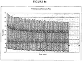
- TMP trans-membrane pressure
- Backpulsing is a generally known technique intended to restore flux and reduce fouling in filters.
- Backpulsing has been done in spiral membranes, for example, by forcing collected permeate backwards into the permeate channel to generate significant overpressure from the permeate side of the membrane.
- backpulsing strategies have not provided uniform local transmembrane pressures along the permeate side of the membrane.
- the pressure gradient within the permeate space has tended to be relatively higher at the permeate backflow inlet and relatively lower at distal locations in the permeate channel from the backflow source. Therefore, the level of localized defouling and flux restoration has varied considerably and unpredictably along the axial length of the membrane.
- Alumina-based ceramic membranes are described as the filtering means, which were cleaned using a cycle of 1.5 weight percent NaOH and 1.5 weight percent nitric acid with use of the UTMP system as a backwashing mechanism.
- the backwashing cycle as described by Brandsma et al. involves use of external chemicals to clean the ceramic membrane.
- the use of external harsh chemicals and significant production down times associated with their use to clean filters is non-ideal.
- Crossflow filtration can also be used to separate like solutes or components based on differences in molecular weight.
- Sugar separation employing nanofiltration is one example.
- Separating milk proteins (primarily casein and whey) is another example that is actively being studied by the dairy industry.
- tubular ceramic membranes employing high crossflow velocities There has been some success with tubular ceramic membranes employing high crossflow velocities.
- the hydrodynamics of spiral wound membranes have previously made this type of process very inefficient with polymeric spiral wound membranes, due to the development of a layer of polarized particles that eventually forms during operation.
- This fouling layer leads to reduced fluxes and rejection of solutes, specifically whey proteins.
- the fouling layer development is more extreme as the ratio between TMP and crossflow velocity increases.
- a system that can decouple crossflow from TMP would allow operation under conditions of minimal fouling.
- EP0747111 describes a filtration process using a tubular cross-flow membrane filter where the transmembrane pressure along the entire length of the membrane is controlled to be substantially constant with co-current recirculation of the filtrate
- the invention provides a filtration process according to claim 1.
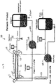
- the invention provides a filtration process comprising providing a spiral wound membrane module including a membrane defining opposing permeate and retentate sides, an inlet and an outlet, a feed stream flowing from the inlet to the outlet axially along the retentate side of the membrane, a permeate stream flowing axially from the inlet to the outlet along the permeate side of the membrane, and a recirculation loop for providing co-current permeate recirculation flow to the module; and adjusting the flow rate of the permeate stream to provide baseline pressures at the inlet and the outlet on the permeate and retentate sides of the membrane such that the difference in baseline pressures between the permeate and retentate sides of the membrane is substantially the same at the inlet and the outlet, wherein the baseline pressure on the permeate side of the membrane is greater at the inlet than the baseline pressure at the outlet and the baseline pressure on the retentate side of the membrane is greater at the inlet than the baseline pressure at the outlet.
- the process further comprises periodically adjusting the pressure on the permeate side of the membrane to reduce the difference in pressures between the permeate and retentate sides of the membrane at the inlet and the outlet by at least about 50% relative to the difference between the baseline pressures.
- the difference in pressures between the permeate and retentate sides of the membrane is reduced to essentially zero at the inlet and the outlet.
- periodically adjusting the pressure on the permeate side of the membrane occurs at approximately 1 to 30 minute intervals for approximately 1 to 10 second durations, and intervening time periods comprise separation phases of operation.
- the process further comprises periodically performing a rUTMP process on said permeate side of the membrane, by either increasing the permeate pressure or decreasing the retentate pressure, resulting in a controllable overpressurization on the permeate side of the membrane in comparison with the pressure on the retentate side of the membrane to provide backflow across the membrane while axial flow is maintained from the inlet to the outlet on both sides of the membrane, wherein difference in pressures between the permeate and retentate sides of the membrane is substantially the same at the inlet and the outlet during said rUTMP process.
- the invention provides a filtration process comprising providing a membrane module including a membrane defining opposite permeate and retentate sides, an inlet and an outlet, a feed stream flowing from the inlet to the outlet axially along the retentate side of the membrane, a permeate stream flowing from the inlet to the outlet along the permeate side of the membrane, and a permeate recirculation loop for providing co-current permeate recirculation flow to the module; adjusting the flow rate of the permeate stream such that the difference in pressures between the permeate and retentate sides of the membrane is substantially the same at the inlet and the outlet, wherein the pressure on the permeate side of the membrane is greater at the inlet than the outlet and the pressure on the retentate side of the membrane is greater at the inlet than the outlet; and periodically performing a rUTMP process on said permeate side of the membrane, by either increasing the permeate pressure or decreasing the retentate pressure, resulting in a controllable
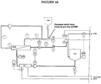
- a filtration process for the separation of a filterable fluid stream by a spiral wound filtration membrane module into a permeate stream and a retentate stream which process comprises: (a) flowing a feed stream to be separated at a feed stream flow rate into a feed stream inlet and axially across a retentate side of a spirally wound membrane under positive pressure in a first flow direction through a retentate channel of the membrane module; (b) withdrawing an axially flowing retentate stream at a retentate outlet of the membrane module; (c) collecting a permeate stream flowing radially within a permeate channel located on a permeate side of the membrane that is opposite to the retentate side thereof, in a permeate collection tube in fluid communication therewith, wherein the collection tube contains at least one flow resistance element; (d)flowing collected permeate stream through the central permeate collection tube to a permeate outlet for discharge from the module; (e)returning a portion of
- the process further comprises (g) periodically adjusting the pressure on the permeate side of the membrane reduce the difference in pressures between the permeate and retentate sides of the membrane at the inlet and the outlet by at least about 50% relative to the difference between the baseline pressures.
- periodically adjusting the pressure on the permeate side of the membrane occurs at approximately 1 minute to 6 hour intervals for approximately 1 to 60 second durations, and intervening time periods comprise separation phases of operation.
- the pressure is periodically reduced on the permeate side of the membrane the difference in pressures between the permeate and retentate sides of the membrane is reduced to essentially zero at the inlet and the outlet.
- the process further comprises (g) periodically performing a rUTMP process on said permeate side of the membrane, by either increasing the permeate pressure or decreasing the retentate pressure, resulting in a controllable overpressurization on the permeate side of the membrane in comparison with the pressure on the retentate side of the membrane to provide backflow across the membrane while axial flow is maintained from the inlet to the outlet on both sides of the membrane, wherein difference in pressures between the permeate and retentate sides of the membrane is substantially the same at the inlet and the outlet during said rUTMP process.
- the rUTMP process occurs periodically at approximately 1 minute to 6 hour intervals for approximately 1 to 60 second durations, and intervening time periods comprise separation phases of operation.
- transmembrane pressure varies less than 40% along the entire length of the membrane as compared to TMP value at either axial end of the membrane.
- the retentate and permeate channels are continuously maintained under positive pressures of about 0.1 to about 10 bar during said rUTMP process.
- a flow resistance element is included on the permeate side of the membrane, wherein permeate flows through the flow resistance element, and wherein the flow rate of permeate flowing through the flow resistance element is varied to create the controlled pressure gradient.
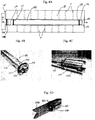
- the flow resistance element is selected from the group consisting of a tapered unitary insert, a porous media packed within an internal space defined by a collection tube through which permeate flows, a static mixing device housed within a collection tube through which permeate flows, and at least one baffle extending radially inward from an inner wall of a collection tube through which permeate flows.
- the flow resistance element comprises a tapered unitary insert.
- the flow resistance element comprises a tapered unitary insert retained within the collection tube by at least one resilient sealing ring located between the insert and an inner wall of the collection tube, and said tapered unitary insert including at least one groove extending below said resilient sealing ring allowing passage of fluid under the sealing ring and along an outer surface of the tapered unitary insert.
- the flow resistance element comprises a porous media selected from beads and foams.
- the flow resistance element comprises spherical polymeric beads.
- the flow resistance element comprises a static mixing device.
- the membrane is selected from a PVDF, a polysulfone, or a polyether sulfone membrane, and said membrane having a pore size of about 0.005 to about 5 micrometers.
- the membrane comprises a polysulfone or a polyether sulfone membrane having a pore size of about 0.005 to about 2 micrometers.
- the feed stream comprises a polypeptide, a nucleic acid, a glycoprotein, or a biopolymer.
- the feed stream comprises a fermentation product of a bacterial production organism.
- the bacterial production organism is selected from the group consisting of Bacillus sp, Escherichia sp, Pantoea sp, Streptomyces sp, and Pseudomonas sp.
- the feed stream comprises a fermentation product from a fungal production host.
- the fungal production host is selected from the group consisting of Aspergillus sp, Trichoderma sp, Schizosaccharomyces sp, Saccharomyces sp, Fusarium sp, Humicola sp, Mucor sp, Kluyveromyces sp, Yarrowia sp, Acremonium sp, Neurospora sp, Penicillium sp, Myceliophthora sp, and Thielavia sp.
- the feed stream comprises a protease and filtration is carried out at a temperature maintained at about 15° C or less.
- the feed stream comprises an amylase and filtration is carried out at a temperature maintained at about 55°C or less.
- a filtration system comprising: (a) a spiral wound filtration membrane module, comprising: a spirally wound membrane, a retentate channel extending along a retentate side of the membrane for receiving a feed stream from a feed stream inlet and flow of retentate axially across a retentate side of the membrane to a retentate outlet for discharge from the module; a permeate channel located on a permeate side of the membrane that is opposite to the retentate side, for radial flow of permeate passing through the membrane to a central permeate collection tube in fluid communication therewith, said collection tube containing at least one flow resistance element and defining a fluid channel for flow of collected permeate to a permeate outlet for discharge of collected permeate from the module, and said collection tube has a permeate inlet for introducing at least a portion of discharged permeate back into the collection tube; (b) a permeate pump for returning a portion of the permeate discharged from
- the filtration system further comprises a housing having a first and second axial ends and defining an annular space in which the central permeate collection tube is located; a membrane leaf spirally wound around the permeate collection tube, said membrane leaf comprising a porous member sandwiched between semi-permeable membrane sheets to define the permeate passage as a radial flow channel, and a spacer arranged between windings of the membrane leaf to define the retentate channel, wherein an outer axial edge and lateral side edges of the membrane leaf are sealed and the inner axial edge thereof is in permeate flow communication with said permeate collection tube.
- the permeate pump and feed stream pump further being controllable for periodically overpressurizing the permeate side of the membrane relative to the retentate side sufficient to generate backflow across the membrane from the permeate side to the retentate side while maintaining axial, co-directional positive forward flow in the retentate and permeate channels.
- the feed stream pump is controllable to reduce the feed rate while the permeate pump being controllable to maintain the discharged permeate at a constant return rate. In some embodiments, the permeate pump being controllable to increase return rate of discharged permeate to the permeate inlet while feed stream pump is controllable to maintain the feed stream at a constant rate.
- the flow resistance element is selected from the group consisting of a tapered unitary insert, a porous media packed within an internal space defined by a collection tube through which permeate flows, a static mixing device housed within a collection tube through which permeate flows, and at least one baffle extending radially inward from an inner wall of a collection tube through which permeate flows.
- the flow resistance element comprises a tapered unitary insert.
- the flow resistance element comprises a tapered unitary insert retained within the collection tube by at least one resilient sealing ring located between the insert and an inner wall of the collection tube, and said tapered unitary insert including at least one groove extending below said resilient sealing ring allowing passage of fluid under the sealing ring and along an outer surface of the tapered unitary insert.
- the flow resistance element comprises a porous media comprising spheres packed within an internal space defined by the collection tube.
- the membrane has a filter pore size of from about 0.005 micron to about 5 micron. In some embodiments, the membrane has a filter pore size of from about 0.05 micron to about 0.5 micron. In some embodiments, the membrane is selected from a PVDF, a polysulfone, or a polyether sulfone membrane, and said membrane having a pore size of about 0.005 to about 5 micrometers. In one embodiment, the membrane comprises a polysulfone or a polyether sulfone membrane having a pore size of about 0.005 to about 2 micrometers.
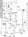
- the filtration system further comprises a plurality of valves for regulating flow of fluid through the system, a plurality of sensors for acquiring data about fluid as it flows through the system, and an electronic data processing network capable of at least receiving, transmitting, processing, and recording data associated with the operation of said pumps, valves, and sensors, wherein the recorded data collected during a flow filtration process is sufficiently comprehensive to allow control of the flow filtration process.
- the sensors are selected from at least one of flow rate sensors, pressure sensors, concentration sensors, pH sensors, conductivity sensors, temperature sensors, turbidity sensors, ultraviolet absorbance sensors, fluorescence sensors, refractive index sensors, osmolarity sensors, dried solids sensors, near infrared light sensors, or Fourier transform infrared light sensors.
- a spiral wound membrane filter module comprising a spirally-wound membrane defining permeate and retentate sides, a permeate collection tube in fluid communication with the permeate side of the membrane, at least one flow resistance element included within the permeate collection tube operable to reduce fluid pressure in permeate flowing between inlet and discharge ends of the collection tube.
- the permeate collection tube is located approximately centrally within the module.
- the flow resistance element is selected from the group consisting of a tapered unitary insert, a porous media packed within an internal space defined by a collection tube through which permeate flows, a static mixing device housed within a collection tube through which permeate flows, and at least one baffle extending radially inward from an inner wall of a collection tube through which permeate flows.
- the flow resistance element comprises a tapered unitary insert.
- the flow resistance element comprises a tapered unitary insert retained within the collection tube by at least one resilient sealing ring located between the insert and an inner wall of the collection tube, and said tapered unitary insert including at least one groove extending below said resilient sealing ring allowing passage of fluid under the sealing ring and along an outer surface of the tapered unitary insert.
- the flow resistance element comprises a porous media packed within an internal space defined by the collection tube.
- the flow resistance element is selected from the group consisting of solid or hollow polymeric spheres, solid polymeric spheres, glass beads, solid ceramic spheres, solid metal spheres, hollow metal spheres, composite spheres, and combinations thereof.
- the flow resistance element comprises a static mixing device housed within the collection tube.
- the flow resistance element comprises an impeller adapted to rotate within the collection tube.
- the flow resistance element comprises at least one baffle extending radially inward from an inner wall of the collection tube.
- methods are provided that refer to processes or actions involved in sample preparation or other procedures. It will be understood that in various embodiments a method or process can be performed in the order of processes as presented, however, in related embodiments the order can be altered as deemed appropriate by one of skill in the art in order to accomplish a desired result.
- Backwashing refers to reversing the direction of flow through the membrane in order to dislodge foulants that are accumulating on the feed or retentate side of the membrane. Fluid flow will be from permeate side to feed/retentate side during backwashing.
- Co-Current Permeate Recirculation refers to when permeate is actively pumped (recirculated) through the permeate side of a membrane system in the same direction as the feed. In our case, this is the flow mode that allows us to achieve UTMP throughout the membrane element.
- Crossflow velocity refers to the superficial velocity of the feed as it travels through the membrane system. This is usually reported in m/s.
- Defouling refers to removal of materials causing fouling from the filtration membrane surface.
- Feed or feed stream refers to the liquid that is to be filtered by the membrane, and during the process it can also be referred to as retentate.
- Flux refers to the rate in which fluid passes through the membrane. This is normally reported in LMH (liters per square meter of membrane area per hour).
- Flow Resistance Element refers to any type of structural unit or feature used to increase the rate of permeate pressure drop within the permeate collection space. This can be done by generating a resistance to flow of permeate through the collection tube of a filter module, either by restricting the flow channel area or generating turbulence. Resistance to flow results in a greater pressure drop than non-restricted flow, allowing for ease in manipulation of a wide range of pressure drops across a membrane filtration unit.
- Fouling should be understood to mean obstruction of pores in a membrane by a gel layer, cake layer, pore blockage by particulate matter or by internal binding of molecules to the membrane pores, or by physical occlusion of the pores by insolubles.
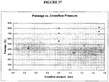
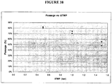
- Passage is the fraction of a solute that passes through the membrane during filtration.
- passage is determined by calculating the ratio of permeate concentration to retentate concentration of the solute and is typically expressed as a percentage.
- Permeate is the liquid that has passed through (permeated) the filtration membrane. It also can be referred to as filtrate.
- Retentate is the liquid that is retained on the feed side of the filtration membrane, and during the process it can also be referred to as feed. It also can be referred to as concentrate.
- rUTMP Reverse Uniform Transmembrane Pressure
- Transmembrane pressure refers to the pressure difference between the retentate side and the permeate side of a membrane.
- Inlet transmembrane pressure refers to the pressure difference between the retentate stream and the permeate stream at the inlet of the membrane module or filtration system.
- Outlet transmembrane pressure refers to the pressure difference between the retentate stream and the permeate stream at the outlet of the membrane module or filtration system.
- Uniform Transmembrane Pressure refers to the pressure difference between the retentate side and the permeate side of a membrane, where the pressure difference is essentially uniform across the length of the filtration membrane and/or where the difference in baseline pressures between the permeate and retentate sides of the membrane is substantially the same at the inlet and the outlet with the baseline pressure at the inlet greater than the baseline pressure at the outlet on both the permeate and retentate sides of the membrane.
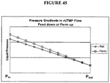
- ⁇ P refers to the pressure drop in the liquid feed between the liquid feed inlet and outlet axially along the retentate side in the membrane system.
- Permeate ⁇ P refers to the pressure drop from inlet to outlet axially along the permeate side of the membrane.
- Volume concentration factor refers to volume of the retentate flowing out of the filtration module divided by the volume of feed flowing into the module for a continuous system or the volume of feed or net broth divided by the volume of retentate in the filtration system for a batch system.
- Biological broth should be understood to mean raw biological fluid produced by culture or fermentation of biological organisms, for example, bacteria, fungi, mammalian or insect cells, or plant cells.
- the biological broth can contain a desired product, fermentation media and cells, or cell debris.
- Biological broths can also be obtained by extraction from biological samples, for example, plant matter or animal tissues or can mean the use of process intermediates, for example, precipitates, crystals or extracts.
- Cell separation should be understood to mean the process by which cells, cell debris, and/or particulates are removed to allow separation and recovery of desired compounds and to clarify a broth for further processing. Cell lysis procedures can precede cell separation.
- Clarification should be understood to mean the removal of particulate matter from a solution.
- Cell paste should be understood to mean material in the retentate portion of the filtration module when filtering a biological broth, and often it refers to the retentate that exits the filtration system.
- Concentration should be understood to mean the removal of water from a broth, and can refer to the use of a membrane, for example, in microfiltration, ultrafiltration, nanofiltration or reversed osmosis processes, chromatography, precipitation, and crystallization. Concentration can also be accomplished by evaporation techniques.
- Concentration Polarization should be understood to mean the accumulation of the retained molecules (gel layer) on the surface of a membrane and can be caused by a combination of factors: transmembrane pressure, crossflow velocity, sample viscosity, and solute concentration.
- Diafiltration should be understood to mean the fractionation process by which smaller components are washed through the membrane, leaving the desired larger components in the retentate. It can be an efficient technique for removing or exchanging salts, buffers, removing detergents, low molecular weight materials, or changing the ionic or pH environment. The process can typically employ a microfiltration or ultrafiltration membrane that is employed to separate a product of interest from a mixture while maintaining the concentration of the larger component constant. Diafiltration can be accomplished with, for example, filtration permeate, water or a buffered salt solution.
- Fluids is used in a general sense, and unless indicated otherwise in a particular context, can encompass liquid materials containing dispersed and or solubilized species, pure liquids, or other flowable materials.
- Fractionation should be understood to mean the preferential separation of molecules based on a physical or chemical properties.
- Gel Layer or Boundary Layer should be understood to mean the microscopically thin layer of compounds that can form on the retentate side of a membrane. It can affect retention of molecules by clogging, or fouling, the membrane surface and thereby reduce the flux.
- Filtration for example, microfiltration or ultrafiltration
- a process that employs membranes to separate larger compounds from smaller compounds, for example, larger molecular weight from smaller molecular weight compounds. It can be used to concentrate mixtures and its efficiency is determined by factors, for example, the molecular weight cut off or pore size and type of the filter media, processing conditions and properties of the mixture being separated.
- the lower molecular weight compounds can be larger than the lower molecular weight compounds separated by ultrafiltration. Relative separation capabilities between ultrafiltration and microfiltration capabilities can be found described in Fig. 1 . Of course, it will be noted that there is some overlap between the two filtration processes.
- microfiltration can be used to separate suspended particles in the range of about 0.05 to about 10 microns, in the range of about 0.1 to 8 microns, in the range of about 1 to about 5 microns, or about 0.05 to about 100 microns, 125 microns, or greater from fluids, such as biological fluids, for example, fermentation broth.
- MWCO Molecular Weight Cut Off
- Permeation Rate is the flow rate, or the volume of permeate per unit time, flowing through a membrane and is typically expressed in liters per minute (LPM).
- Product Yield or Yield is the total amount of product collected in the product stream, usually expressed as a percentage of the total amount in the feedstream.
- Proteins, polypeptides or biologically derived polymers should be understood to mean molecules of biological or biochemical origin or in vitro processes. These are made of condensed building blocks of amino acids and include enzymes, structural proteins and cell derived polymers, for example, celluloses, starch, polyhydroxybutyric acid, and polylactate.
- Product Stream is a permeate or retentate stream that contains a product of interest.
- the product stream is the retentate because the product is retained while the solvent (water) is permeated.
- the solvent water
- he product stream is the permeate because the product passes through the filter while cells and cell debris are retained.
- Product Purity or Purity is the degree of isolation of the product in the product stream. It can be understood to mean the amount of desired compound isolated compared to the sum amount of the other components in the stream and can be expressed as a weight percentage. Alternatively, it can be understood to mean the ratio of the concentration of the product relative to that of another selected component in the product stream and can be expressed in weight percent.
- purity is measured directly or indirectly instrumentally or manually, for example, by determination of enzymatic activity (for example, as determined colorimetrically); and or by product color determination by absorbance measurement, CIELAB formula, or US Pharmacopeia (USP) Monographs, and so forth to measure product color; and or by impurity level measurement (for example, measurement of microbial impurities in fresh product or as part of shelf life studies); and or total protein content or other product component; and or organoleptically by odor, taste, texture, visual color, and so forth (for example, in fresh product or as part of shelf life studies).
- Rejection should be understood to mean the inability of a compound to pass through the filter media because of, for example, the formation of a gel, cake or boundary layer on a membrane surface; electrostatic charge interactions between the compound and a membrane surface; or the small pore size of the membrane.
- Tangential Flow Filtration should be understood to mean a process in which the fluid mixture containing the components to be separated by filtration is recirculated across the plane of the membrane.
- Ultrafiltration should be understood to mean a process that employs membranes to separate large molecular weight compounds from low molecular weight compounds. It is used to concentrate a solution and its efficiency is determined by the molecular weight cut off of the membrane. Relative separation capabilities between ultrafiltration and microfiltration capabilities can be found described in Fig. 1 . Of course, it will be noted that there is some overlap between the two filtration processes. Ultrafiltration can be used to concentrate suspended solids and solutes of molecular weight greater than 1,000 daltons, and a size greater than about 0.005 microns and up to about 0.1 microns.
- Active Permeate Collection refers to a process in which the pressure of the permeate is controlled and the rate at which permeate is collected or removed from the permeate loop is controlled by a valve or other metering device.
- filtration processing is implemented in membrane formats operable to provide unique uniform transmembrane pressure (UTMP) modalities of operation that are effective for membrane fouling control.
- Membrane formats suitable for use with the filtration processes described herein include, for example, spiral, plate and frame, flat sheet, ceramic tube, and hollow fiber systems.
- a filtration process is implemented in a membrane format comprising providing a membrane module including a membrane defining opposing permeate and retentate sides, an inlet and an outlet, a feed stream flowing from the inlet to the outlet axially along the retentate side of the membrane, a permeate stream flowing axially from the inlet to the outlet along the permeate side of the membrane, and a permeate recirculation loop for providing co-current permeate recirculation flow to the module.
- the flow rate and/or pressure of the permeate and/or retentate stream is adjusted to provide baseline pressures at the inlet and the outlet on the permeate and retentate sides of the membrane such that the difference in baseline pressures between the permeate and retentate sides of the membrane is substantially the same at the inlet and the outlet, wherein the baseline pressure on the permeate side of the membrane is greater at the inlet than the baseline pressure at the outlet and the baseline pressure on the retentate side of the membrane is greater at the inlet than the baseline pressure at the outlet.
- the pressure on the permeate side of the membrane is periodically adjusted to reduce the difference in pressures between the permeate and retentate sides of the membrane at the inlet and the outlet by any of at least about 50%, 60%, 70%, 80%, or 90% relative to the difference between the baseline pressures ("reduced UTMP").
- the difference in pressures between the permeate and retentate sides of the membrane is reduced to essentially zero at the inlet and the outlet.
- equal and opposing pressures are provided on the opposite permeate and feed sides of the membrane such that a zero or null pressure gradient condition is created across the membrane.
- this null UTMP mode of operation can be induced one or more times during a filtration production run, such as intermittently or periodically at regular time intervals or irregular time intervals (e.g., as needed) during otherwise normal operational flow conditions of co-current permeate recirculation conditions, and particularly UTMP conditions.
- reduced or null UTMP occurs at intervals of 1 minute to 6 hours, 4 hours to 8 hours, 1 minute to 30 minutes, 1 minute to 10 minutes, 10 minutes to 30 minutes, or 10 minutes to 1 hour, for a duration of 1 second to 1 minute, 1 second to 30 seconds, or 1 second to 10 seconds.
- the duration refers to the time during which the TMP is reduced to the desired level, and is not inclusive of the amount of time that it takes for the permeate to reach the reduced pressure.
- this reduced or null UTMP mode of operation can be implemented on a spiral wound membrane, although not limited thereto. It also can be implemented on a variety of other microfiltration formats plate and frame, ceramic tubes, hollow fiber, and so forth.
- reverse uniform transmembrane pressure rUTMP
- the permeate side of the membrane is periodically backwashed, i.e., a reverse flow through the membrane is achieved by either increasing the permeate pressure or decreasing the retentate pressure, resulting in a controllable overpressurization on the permeate side of the membrane in comparison with the pressure on the retentate side of the membrane.
- This controllable overpressurization condition provides backflow across the membrane while axial flow is maintained from the inlet to the outlet on both sides of the membrane.
- the difference in pressures between the permeate and retentate sides of the membrane is substantially the same at the inlet and the outlet during backwashing (rUTMP).
- the backwashing (rUTMP) phase removes fouling cake or other fouling material from the membrane.
- periodic internal reverse flow can be provided by increasing the pressure of permeate and/or decreasing the pressure of retentate relative to one another, for example, by adjusting the flow rate(s) of permeate and/or retentate, and/or adjusting the recirculation rate of permeate, resulting in a controllable overpressurization on the permeate side.
- Backflow across the membrane is provided while positive flow is maintained in both the feed and permeate lines.
- a UTMP process has two defouling phases in which the first phase involves providing reduced UTMP or nUTMP conditions such as described herein followed by a subsequent phase of the rUTMP cycle involving providing the controllable overpressurization condition.
- a filtration process such as at least one of the processes referenced above, is implemented in a spiral wound membrane format wherein at least one flow resistance element (FRE) is included within a permeate space, such as a collection tube, of the spiral wound filtration module.
- the FRE is used in combination with co-current permeate recirculation to the filter module via a permeate recirculation loop.
- the flow resistance element partially impedes or obstructs forward movement of permeate through the collection tube such that a pressure drop can be created within the collection tube between the permeate inlet and outlet thereof.
- a controlled pressure gradient on the permeate side By altering the flow rate of permeate via the FRE, a controlled pressure gradient on the permeate side, close in magnitude to the retentate pressure gradient, can be induced along the length of the permeate side of the membrane.
- FRE flow resistance element
- Positive permeate side pressure thus can build in a controlled manner in the permeate channel during the intermittent reduced or null UTMP and/or rUTMP phases while maintaining forward flow of both the feed stream and recirculated permeate streams through the module.
- Resulting backpressures and fluxes are gentle and uniform along the length of the membrane, avoiding excessive overpressure or underpressure, resulting in optimal reversal of fouling and minimizing the risk of membrane damage, for example, delamination of a spiral wound membrane module.
- a result achieved is significantly higher fluxes, and, the ability to efficiently process liquids containing high concentrations of solids that would be extremely problematic in a spiral membrane system.
- the maintenance of positive flow through the retentate passage during reduced or null UTMP and/or rUTMP phases facilitates removal of partly dislodged fouling materials from the retentate side of the membrane which can be swept away before they can settle back onto the retentate side when backwash pressure is relieved.
- substantially uniform defouling is achieved along the length of the membrane, the flux is restored substantially uniformly along the length of the membrane. This is a gentle defouling regimen that minimizes the risk of mechanical damage to polymeric membranes, for example, spiral wound designs, while maintaining sufficient crossflow and backflow to reverse fouling by flushing out particulates and disrupting the cake layer on the membrane. Also, fouling due to overpressure is avoided.
- the flow resistance elements can take various forms. In various embodiments they are a passive means, for example, a tapered unitary insert, porous media for example, beads or foams. In other various embodiments they are active means, for example, a static mixer, or other means of inducing resistance to fluid flow through the collection tube effective for a pressure drop to develop between the inlet and outlet to the tube.
- the magnitude of the pressure gradient on the permeate side is determined by the linear resistance or porosity of the flow resistance elements and the rate of the recirculation flow, allowing for independent control of TMP and crossflow rate.
- uniform transmembrane pressure UTMP
- the entire membrane is used effectively, not just a portion as when the permeate pressure is unconstrained. Furthermore, fouling due to overpressure on the retentate side is avoided. This results in significantly higher product passages.
- significantly reduced membrane fouling in spiral membrane filtration systems is achieved and maintained, thereby allowing for improved recovery and maintenance of high fluxes and passages after numerous filtration cycles (i.e. separation/defouling cycles) spanning significant production time periods.
- Embodiments according to the present teachings can create new opportunities for use of spiral membrane-based filtration in separation processing applied to high solids content feeds.
- significant flux advantages from UTMP are obtained in a spiral membrane format on liquids with high solids concentrations.
- processes of embodiments herein can also be implemented on feed mixtures having solids loads that are several orders of magnitude larger than many conventional applications of spiral membranes.
- the feed stream to be separated comprises at least 25%, for example, at least 15%, and, for example, at least 5%, dispersed solids content.
- a lower crossflow when filtering certain high concentration broths, for example, B. subtilis broths results in an initial higher flux. This result is surprising and unexpected as a high crossflow velocity is often cited in the membrane field as an important factor in establishing high fluxes higher velocities being thought necessary to sweep the membrane surface clean and maintain flux.
- defouling phases of processes according to embodiments of the present teachings are controlled to occur periodically, for example, at intervals of approximately 1 minute to 6 hours, 4 hours to 8 hours, 1 minute to 30 minutes, 1 minute to 10 minutes, 10 minutes to 30 minutes, or 10 minutes to 1 hour, for a duration of 1 second to 1 minute, 1 second to 30 seconds, or 1 second to 10 seconds.
- the retentate and permeate passages or channels are continuously maintained under positive pressures of about 0.1 to about 10 bar during defouling cycles.
- transmembrane pressure varies less than 40%, for example, less than 20%, and, for example, less than 10%, along the entire axial length of the membrane as compared to TMP value at either axial end of the membrane.
- process fluid is used in the backwashing regimen, such that external chemicals and significant process disruptions are not required for filter cleaning.
- the feed stream can comprise a protein, a polypeptide, a nucleic acid, a glycoprotein, or a biopolymer.
- the feed stream can comprise a fermentation product of a bacterial production organism, for example, Bacillus sp, Escherichia sp, Pantoea sp, Streptomyces sp, and or Pseudomonas sp.
- the feed stream can comprise a fermentation product from a fungal production host, for example, Aspergillus sp, Trichoderma sp, Schizosaccharomyces sp, Saccharomyces sp, Fusarium sp, Humicola sp, Mucor sp, Kluyveromyces sp, Yarrowia sp, Acremonium sp, Neurospora sp, Penicillium sp, Myceliophthora sp, and or Thielavia sp.
- a fungal production host for example, Aspergillus sp, Trichoderma sp, Schizosaccharomyces sp, Saccharomyces sp, Fusarium sp, Humicola sp, Mucor sp, Kluyveromyces sp, Yarrowia sp, Acremonium sp, Neurospora sp, Penicillium sp, Myceli
- the feed stream can comprise a serine protease and filtration is carried out at a temperature maintained at from about 12°C to about 18°C, or amylase and filtration is carried out at a temperature maintained at from about 20°C or 35°C to about 45°C or about 60°C.
- the feed stream is a dairy feed stream, for example, milk (e.g., raw whole milk, whole milk, skim milk), whey, whey hydrolysates, buttermilk, curdled casein (acid or enzyme), or the like.
- filtration systems for practicing the processes are also provided.
- the filtration system can comprise a spiral wound filtration membrane module, a permeate pump for returning a portion of the permeate discharged from a permeate collection tube containing at least one flow resistance element at a controllable rate into the permeate inlet of the collection tube, and a feed stream pump for feeding the feed stream to the feed stream inlet at a controllable rate.
- a controller either manual, automatic or a combination thereof, for joint control of the permeate pump and feed stream pump is provided such the respective feed stream and permeate flow rates into the membrane module are mutually controllable effective to provide alternating separation and defouling phases during a production run wherein uniform transmembrane pressure is substantially maintained axially along the membrane during both phases of operation.
- pumps and/or valves may be independently controlled.
- the filtration system can comprise a plurality of valves for regulating flow of fluid through the system, a plurality of sensors for acquiring data about fluid as it flows through the system, and an electronic data processing network capable of at least receiving, transmitting, processing, and recording data associated with the operation of the pumps, valves, and sensors, wherein the recorded data collected during a flow filtration process is sufficiently comprehensive to allow automated control of the filtration process.
- the membrane can comprise a PVDF, a polysulfone or polyether sulfone membrane having a pore size of about 0.005 to about 5 micrometers, or about 0.005 to about 20 micrometers.
- the permeate loop of the operating system may include a valve that allows removal of permeate from the circulation loop.
- the permeate loop includes a valve, located upstream of the permeate pump, that is connected to a pressurized water line.
- the valve is controllable. When the water pressure is set higher then the permeate pressure inside the loop opening this valve allows to overpressurize the permeate loop relative to the retentate side sufficient to generate backflow across the membrane from the permeate side to the retentate side while maintaining axial, co-directional positive forward flow in the retentate and permeate channels.
- a spiral wound membrane filter module comprising a spirally-wound membrane defining permeate and retentate sides, a permeate collection tube in fluid communication with the permeate side of the membrane, at least one flow resistance element included within the permeate collection tube operable to reduce fluid pressure in permeate flowing between inlet and discharge ends of the collection tube.
- Filtration processes and systems of various embodiments according to the present teachings also can provide significant cost reductions as well as improvements in product quality.
- they are applicable to microfiltration, ultrafiltration, nanofiltration, singly or in overlapping scenarios thereof.
- the cost reduction derives both from high yields in efficiently separating and/or concentrating solutions and/or solutes from high solids suspensions and from elimination of raw materials used in other filtration operations.
- Various embodiments of the present teachings further enable cost savings from reductions in membrane costs and associated equipment resulting from higher permeate fluxes per unit of membrane area and potentially from improved cleaning, and reduced risk of damage to membranes during defouling.
- Various embodiments of the present teachings have application, in various embodiments, in fermentation broths, pharmaceuticals, chemicals, dairy, soy, and other food industries, for example, fruit juice, vegetable juice, brewing, distilling, and so forth.
- Various embodiments include recovery and purification of enzymes or other macromolecules from fermentation broth, juice clarification, and milk decontamination or concentration and/or separation of components of milk, and the like.
- a filtration process for the separation of a filterable fluid stream by a spiral wound filtration membrane module into a permeate stream and a retentate stream, in which the process comprises flowing a feed stream to be separated into a feed stream inlet and axially across a retentate side of a spirally wound membrane under positive pressure in a first flow direction through a retentate passage of the membrane module.
- An axially flowing retentate stream is withdrawn at a retentate outlet of the membrane module.
- a permeate stream flowing radially within a permeate passage located on a permeate side of the membrane module that is opposite to the retentate side is collected in a central permeate collection tube in fluid communication therewith.
- the collection tube contains at least one flow resistance element that partially impedes but does not block forward flow of permeate through the tube.
- the collected permeate stream flows through the central permeate collection tube to a permeate outlet for discharge from the module.
- a portion of permeate discharged from said permeate collection tube is returned to the tube through a permeate inlet to provide co-current permeate recirculation through the membrane module during separation processing.
- the permeate and feed stream flow rates into the membrane module are mutually controlled effective to provide successive filtration cycles comprising alternating separation and defouling phases during a production run during which uniform transmembrane pressure is maintained along the axial length of the membrane in both phases of operation.
- the pressure on the permeate side of the membrane is periodically adjusted to reduce the difference in pressures between the permeate and retentate sides of the membrane at the inlet and the outlet by at least about 50% relative to the difference between the baseline pressures.
- the filtration system 100 includes a spiral membrane 101, permeate pump 103, feed stream pump 109, and other components, for example, valves, pressure gauges, temperature gauges, flow meters, feed/collection tanks, and so forth, for providing an integrated operational separation system.
- Spiral wound filtration membrane module 101 is arranged for providing co-current permeate flow via permeate recirculation loop 104 including control valve 106 and permeate pump 103.
- Permeate pump 103 is controllable to return a portion of permeate discharged at permeate outlet 105 of the module 101 (i.e., an outlet end of a permeate collection tube) at a controllable rate into a permeate inlet 107 of the permeate collection tube disposed within filter module 101.
- Feed stream pump 109 is provided for feeding a feed stream to be separated to a feed stream inlet 111 of filter module 101 at a controllable rate.
- the feed stream is passed through a heat exchanger 115 before introduction into the filter module 101.
- Retentate exits filter module 101 at outlet 113 located at the opposite axial end of the module.
- UTMP Uniform transmembrane pressure
- the spiral membrane 101, permeate pump 103, feed stream pump 109 and valving 106 can be controlled such that UTMP modality is provided during the separation phases of a production run that are alternated with null UTMP (nUTMP) or reverse UTMP (rUTMP) phases provided at regulated time intervals as intermittent defouling phases applied to the membrane along its entire axial length.
- nUTMP null UTMP
- rUTMP reverse UTMP
- axial length is determined parallel to the axial dimension 110 of the filter module 101.
- the spiral membrane 101 has features in common with the filter module illustrated in Fig. 3A , although not limited thereto.
- Fig. 3B shows the spiral membrane 101 in a cross-section according to one non-limiting embodiment of the present teachings.
- the spiral membrane also can have significant modifications according to other various embodiments of the present teachings, such as illustrated in Figs. 4-8 and described in more detail below.
- the spiral membrane 101 generally includes a perforated central collection tube 10 having openings 11 for introduction of permeate from permeate channel 12 into the interior space 13 of the tube 10.
- the tube 10 can be a semi-rigid or rigid material, for example, plastic, metal, ceramic construction, and so forth.
- Permeate channel 12 is sandwiched between membranes 14 and 15 to form a membrane leaf 16 that is spirally wrapped around tube 10 one or multiple times.
- the edges of the membrane and permeate channel layer that are not adjacent the collection tube generally are sealed, for example, in a conventional manner with adhesive or other sealing means, to retain and direct permeate flow within the permeate channel between the membranes to the tube 10.
- Permeate channel 12 can be a porous media layer or material, for example, a sheet or strip of porous cloth, felt, netting, or other porous material.
- the membranes 14 and 15 can be flexible sheet materials that are semi-permeable to dispersed discrete solid materials, depending on the size of the dispersed materials.
- the membranes can be microporous polymeric sheet materials, for example, microporous sheets of thermoplastic films.
- a feed channel spacer 17 separates layers of the wound leaf 16, and which is used for introduction of fluid material to be separated into the spiral membrane 101. To simplify this illustration, only a partial wrapping of membrane leaf 16 around tube 10 is shown.
- the radial dimension 112 of the filter module 101 is orthogonal to the axial dimension 110.
- a flow resistance element can be provided in the permeate space 13.
- a flow resistance element or "FRE" can be an individual component or a plurality of components used in unison, as will be better understood from the following non-limiting illustrations.
- a tapered unitary insert 102 is positioned within the collection tube 10.
- the tube openings 11 shown in this figure through which permeate is introduced into the interior space 13 of the tube 10 from the spiral membrane 101 during a filtration operation are merely illustrative, as the number and frequency and size thereof can vary and differ in practice.
- the tapered insert 102 has one axial end 114 near tube inlet 107 having a cross-sectional diameter that is larger than that of the opposite axial end 116 nearer the tube outlet 105.
- the tapered insert 102 generally has a negative (decreasing) slope between its ends 114 and 116.
- the tapered insert 102 can have a metal, plastic, ceramic or other type of construction which is stable and durable in the permeate environment.
- the tapered design of insert 102 promotes a more even pressure drop gradient as permeation through the membrane contributes to the total permeate flow along the axial length of the permeate collection tube.
- a resilient sealing ring or gasket 117, 118, such as an O-ring, is located between the insert 102 and an inner wall 119 of the collection tube 10 at each axial end of the insert 102 to retain the insert in lateral position within interior space 13 of tube 10.
- An anti-telescoping device (ATD) 108 is illustrated as holding one of the opposite longitudinal ends 121 of the insert 102 in place to prevent longitudinal movement thereof.
- a plurality of grooves 120 are provided in the surface of the tapered insert 102 at each axial end 114 and 116 thereof that extend below the location where the resilient sealing ring 117 or 118, as applicable, is installed, allowing passage of permeate fluid under the sealing ring and along an outer surface 121 of the tapered unitary insert 102 below the sealing ring.
- This illustration shows the grooves at the inlet side end 114 of the tapered insert 102, however it will be appreciated that a similar grooved configuration is applied at the opposite axial end of the insert 102 to allow for permeate flow by the region where seal ring 118 is used to retain the axial end 116 in fixed lateral position relative to inner wall 119.
- the ATD also can include a resilient ring 108A sealing means where fitted within the inlet 107 of the interior space 13 of tube 10. Grooves (not shown) can be provided on the surface portion of the ATD extending into the inlet of the tube 10 similar to that provided on the insert 102 to allow permeate flow into the tube space 13.
- a similar ATD retention system can be used at the opposite end of the insert 102 to stabilize both opposite ends of the insert 102.
- Fig. 4C illustrates an alternative axial end 114A for the tapered insert 102 which is configured to mechanically interlock with a corresponding portion of the ATD 108 (not shown).
- the end of the insert was modified. 60 degree cuts were placed in the center of the ends to help distribute flow to the perimeter of the insert.
- Fig. 4D illustrates an alternative axial end 114B for the tapered insert 102 which is configured to mechanically interlock with a corresponding portion of the ATD (not shown).
- the opposite axial ends of the insert 102 are removed and grooves 117A are increased under the locations where o-rings 117 are received.
- centered thin fins 114B are tacked on the ends thereof.
- the tapered insert 102 has a significant effect on the permeate recirculation flow rates, decreasing flow rates to maintain a significant pressure drop, e.g., approximately 2 bar, across the membranes. Compared to a constant diameter insert, the tapered insert 102 has extremely similar results. Increasing the diameter of the insert, i.e., decreasing flow area within the permeate tube, results in a decrease in required flow rate to maintain a significant pressure drop, e.g., approximately 2 bar. Although not desiring to be bound to theory, the negatively tapered shaft or insert is thought to result in a gradual increase in flow area, which creates a higher pressure at the inlet and a lower pressure at the outlet of the permeate collection tube. The tapered insert is designed to accommodate for the added permeate flow down the permeate tube as well as creating the desired significant pressure drop, e.g., approximately 2 bar pressure drop.
- the flow resistance element in the collection tube has the effect of inducing a pressure drop in the permeate space between the inlet and outlet thereof.
- the FRE dampens fluid back pressure exerted against the permeate side of the membranes during reverse flow phases, allowing positive yet gentle and more uniform backpressure to be applied along the length of the membrane.
- the spheres can be discrete solid or hollow plastic balls, glass beads, solid ceramic spheres, solid or hollow metal spheres, composite spheres, and the like.
- the flow resistance elements are not limited to spherical geometric shapes.
- the flow resistance material should be stable in and inert to the fluid environment. Enough interstitial void space is reserved in packed tube 10 so that forward permeate flow can be maintained.
- the flow resistance element alternatively can be a static mixer 20, for example, a radially extending impeller fixed for rotation on a rotatable rod that is axially inserted within space 13, and which can be mechanically driven in rotation by a motor or other drive means (not shown) located outside the tube 10, to agitate the permeate fluid within the tube 10.
- a static mixer 20 for example, a radially extending impeller fixed for rotation on a rotatable rod that is axially inserted within space 13, and which can be mechanically driven in rotation by a motor or other drive means (not shown) located outside the tube 10, to agitate the permeate fluid within the tube 10.
- One or a plurality of static mixers can be arranged in this manner inside tube 10 to disrupt laminar flow of permeate through tube 10 at a single location or multiple locations at regular or irregular intervals along the length of the tube.
- the flow resistance element can be one or more baffles 201 and 202 that extend radially inwardly from an inner wall 119 of the collection tube 10 into the permeate space 13 defined by the collection tube.
- the plurality of baffles 201 and 202, and so forth can be arranged along the inner wall 119 of the collection tube 10 in a staggered, spaced formation at regular or irregular intervals along the lengthwise direction of the tube 10 to induce non-linear flow, such as a serpentine directional flow, of permeate through the tube 10.
- the baffles can have other shapes and configurations.
- the baffles can be formed integrally at the inner wall of the permeate collection tube 10, or, alternatively, they can be retrofitted into existing collection tube structures.
- a generally tubular shaped insert bearing baffles on its inner surface can be provided having an outer diameter sized relative to an inner diameter of an existing collection tube to allow the insert to be inserted or telescoped inside the existing collection tube.
- the flow resistance elements 18, 20, 201, 202, and so forth, partially impede or obstruct forward movement of permeate through the collection tube 10 and disrupt laminar flow of the permeate through the collection tube, such that a pressure drop can be created within the collection tube along the length of the collection tube between its inlet and outlet.
- Positive permeate side pressure can build in a controlled manner in the permeate channel 12 during the intermittent defouling phases and while maintaining forward axial flow of both the feed stream and recirculated permeate streams.
- the permeate pump 103 and feed stream pump 109 are controllable such that a substantially uniform transmembrane pressure is maintainable between the retentate and permeate sides of the filter along the entire axial length of the membrane between the inlet and outlet of the module.
- the filtration system comprises valves for regulating flow of fluid through the system.
- the filtration system can further comprise a plurality of sensors for acquiring data about fluid as it flows through the system, an electronic data processing network capable of at least receiving, transmitting, processing, and recording data associated with the operation of the pumps, valves, and sensors and wherein the recorded data collected during a flow filtration process is sufficiently comprehensive to allow automated control of the flow filtration process.
- Fig. 9 is a simplified drawing of a comparison microfiltration system without co-current permeate recirculation.
- Fig. 10 is a graphical representation of the fluid pressures in a spiral wound filtration system according to Fig. 9 .
- the feed side has a significant pressure drop though the system because of the resistance to flow it encounters as is passes through the narrow feed channels within the membrane element.
- Permeate is collected in a hollow central tube with negligible resistance.
- permeate flow rates are a fraction of retentate flow rates, there is no measurable ⁇ P.
- the permeate typically discharges to atmospheric pressure, so there is no significant fluid pressure on the permeate side of the system.
- a typical phenomenon of this system is the great difference in TMPs between the inlet (TMP1) and the outlet (TMP2) of the system.
- Fig. 11 is graphical representation of fluid pressures in UTMP mode as applied to a spiral wound filtration system according to Fig. 2 .
- a flow resistance element for example, the tube receives a tapered insert or a packing of plastic spheres, a measurable and controllable fluid pressure is introduced on the permeate side of the membrane system. This allows for an essentially constant TMP across the length of the membrane, independent of cross flow velocity.
- Fig. 12 is a graphical representation of the fluid pressures when a backwashing operation is employed on a spiral wound filtration system according to Fig. 2 except without including a flow resistance element.
- the permeate is pumped back into the permeate tube from the outlet side. Because there is no measurable drop in the permeate tube, the permeate pressure will quickly equalize across the length of the membrane system.
- the retentate feed is kept on, large variations in the magnitude of backwash pressure occur at various points along the length of the system. In this scenario, the inlet side will not see enough backwash to efficiently remove foulants and the outlet side is subjected to reverse flow pressures that can be extremely detrimental to a spiral wound membrane.
- Fig. 13 is a graphical representation of the fluid pressures when a backwashing operation is employed on a spiral wound filtration system according to Fig. 2 when the feed is turned off during backwashing.
- the advantage of this mode is that a uniform reverse pressure is achieved, so all point of the membrane see essentially the same backwash rate and extreme reverse pressures can be avoided.
- crossflow is absent on the retentate side, so even though foulants might be dislodged from the surface, they will not be efficiently removed from the liquid-membrane interface. So there is a high probability for rapid refouling due to the high concentration of foulants at the interface once positive feed pressure is resumed.
- fouling is increased when the driving force pulling particles onto the membrane resulting from the transmembrane pressure (TMP) is greater than the ability for the tangential fluid flow to sweep particles off the surface.
- TMP transmembrane pressure
- Optimal microfiltration flux and passage requires control of TMP within a narrow range. When TMP is too low, fluxes are suboptimal, and at high TMP, rapid and irreversible fouling can occur. Comparison systems illustrated by reference to Fig. 12 can not achieve the correct balance in this respect over substantial axial lengths of the membrane.
- Fig. 14 is a graphical representation of the fluid pressures in rUTMP mode enabled by CCPR as employed on a spiral wound filtration system according to Fig. 2 .
- the feed pump can be slowed down, or the permeate recirculation pump can be sped up in order to overpressurize the permeate side of the membrane system.
- an essentially equivalent backwash flow is achieved throughout the membrane system, with no excessive reverse pressures and a quick, gentle method of achieving the reverse flow.
- Ample retentate crossflow is maintained to sweep away foulants that are dislodged from the retentate side membrane surface.
- the combination of co-current permeate recirculation and inclusion of a flow resistance element within the permeate space of spiral wound membrane modules has been found to allow for independent control of crossflow velocity and transmembrane pressures, thereby enabling Uniform Trans Membrane Pressure operation within the spiral membrane.
- the combination also allows for backflushing by means of Reverse Uniform Trans Membrane Pressure (rUTMP), which is a operational modality for sustaining surprisingly high and fluxes and passages along the membrane.
- rUTMP Reverse Uniform Trans Membrane Pressure
- the rUTMP flow conditions result in backflow across the membrane while axial flow is maintained in both the feed and permeate line. Resulting backpressures and fluxes are gentle and uniform along the length of the membrane, avoiding overpressure or underpressure, resulting in optimal reversal of fouling.
- Processes according to various embodiments of the present teachings can achieve a uniform backpressure by either increasing the pump speed of the permeate pump or by decreasing the retentate pump speed.
- Figs. 15A-15I show different flow paths of retentate and permeate during operational modes that may be conducted on the microfiltration system of the present teachings. Although any one or more of the modes illustrated in these figures may be included in a processing operation of the present teachings, the modes illustrated in Figs. 15B-15E are of particular interest in accordance with various embodiments of the present invention.
- active flows are represented by heavier lines, e.g., the feed stream to, and the permeate and retentate streams exiting from, the filtration module SWM as illustrated in Fig. 15B .
- darkly-shaded valves e.g., valve 43HV45 in Fig. 15B
- lightly-shaded valves e.g., valve 43VC60 in Fig. 15B
- Fig. 16 is a chart summarizing the basic equipment settings for providing the various operational conditions illustrated in Figs. 15A-15I .
- the glycol supply and return line valves to the heat exchanger, diafiltration supply water valves, and compressed air supply valves, to the filtration system are opened as part of start-up operations. Instrumentation is set to the start-up defaults such as indicated in Fig. 16 .
- all automated parts valves, pumps, etc.
- the filtration system may be prepped for process by running in water recirculation mode first. Water recirculation mode is the start point of all other operational modes. All other modes transition from water recirculation.
- Feed Flow Only FFO and Co-current Permeate Flow (CCPR)
- CCPR Co-current Permeate Flow
- the filtration system in Figs. 15A-15I includes the spiral membrane SWM, permeate pump 41PF40, feed stream pump 41PF30, and other components, for example, valves (43HV41, 43HV45, 43VA40, 43VC60, 43HV42, 42VC60, 41VC62, 72VC60), pressure gauges (PI), pressure-valve controllers (PIC), pressure transmitters (PT), temperature transmitters (TT), temperature-valve controller (TIC), flow meters (FI), flow indication transmitters (FIT), flow-valve controllers (FIC), feed/collection tanks (TANK), heat exchanger (HE), tank level transmitter (LT), feed-valve controller (LICZ), and so forth, for providing an integrated operational separation system.
- valves 43HV41, 43HV45, 43VA40, 43VC60, 43HV42, 42VC60, 41VC62, 72VC60
- pressure gauges PI
- pressure-valve controllers PIC
- pressure transmitters PT
- TT temperature transmitters
- TIC temperature
- spiral wound filtration membrane module SWM is arranged for providing co-current permeate flow via permeate recirculation loop 1501 (e.g., see Figs. 15B-15E ).
- a portion of permeate discharged at the permeate outlet of module SWM i.e., an outlet end of a permeate collection tube
- a feed stream 1502 is pumped to a feed stream inlet of filter module SWM at a controllable rate.
- the feed stream is passed through a heat exchanger HE before introduction into the filter module SWM.
- Retentate exits filter module SWM at an outlet located at the opposite axial end of the SWM module.
- Fig. 15A illustrates forward feed conditions (FFO Mode) without CCPR conditions being provided. No co-current permeate recirculation is provided in this configuration.
- a CCPR flow configuration is illustrated for providing UTMP conditions over a spiral membrane as the normal operating condition of the process according to an embodiment of the present teachings.
- Figs. 15G and 15I which are discussed in more detail below, also show variations on this flow mode.
- a spiral wound membrane system having the illustrated process lay-out can be used to implement null UTMP (nUTMP) embodiments according to the present teachings.
- No permeate is collected in this mode of operation.
- Valve 42VC60, the permeate recirculation pump, and the feed pump, are held at their established settings in order to maintain the feed side pressure set-points and the crossflow rates of both the permeate and the retentate.
- Valve 43VC60 is closed during this mode of operation. Enough co-current permeate recirculation is provided to equalize with the feed stream such that TMP is substantially zero everywhere axially along the membrane.
- the nUTMP and rUTMP flow configurations illustrated in Figs. 15C-15E represent those specific phases only of a nUTMP and/or rUTMP process, and for the remainder of the process time, the process flows are represented by CCPR mode such as illustrated in Fig. 15B .
- a spiral wound membrane system having the illustrated process lay-out alternatively can be used to implement reverse UTMP (rUTMP) embodiments according to the present teachings.
- the first phase of rUTMP according to either Fig. 15D or 15E is the provision of nUTMP conditions such as illustrated in Fig. 15C .
- the equipment settings indicated in Fig. 16 are provided to overpressurize the permeate side of the system.
- pulse valve 43VA40 may be opened to overpressurize the permeate side until the net flow in FD4261 approaches zero, indicating backwashing conditions have been established over the membrane of the module SWM.
- Fig. 15E this is an alternative mode for providing rUTMP conditions to that illustrated in Fig. 15D .
- the first phase of rUTMP according to Fig. 15E also is the provision of nUTMP conditions such as illustrated in Fig. 15C .
- the feed side of the system is underpressurized using the equipment settings such as indicated in Fig. 16 , indicating backwashing conditions have been established over the membrane of the module SWM.
- valve 41VC62 may be opened to allow bypass of feed flow from the outlet to the inlet of the feed pump, thereby reducing the feed flow to the membrane.
- Exemplary control logic for providing the nUTMP or rUTMP modes of operation in the microfiltration system of Figs. 15C-E includes the following steps, with the following timer definitions:
- Fig. 15F like Fig. 15A , illustrates forward feed conditions (FFO Mode) without CCPR conditions being provided. No co-current permeate recirculation is provided in this configuration. Unlike Fig. 15A , valves 41VC60 and 41VH41 are opened to allow introduction of diafiltration water in this illustration.
- Fig. 15G like Fig. 15B , illustrates CCPR conditions being provided.
- valves 41VC60 and 41VH41 are opened to allow introduction of diafiltration water in this illustration.
- Fig. 15H like Fig. 15A , illustrates forward feed conditions only, without co-current permeate recirculation (FFO Mode). No co-current permeate recirculation is provided in this configuration.
- permeate valve 43VA42 is opened to allow diversion of a portion of the permeate to retentate holding tank 41B20 for recycling permeate to the retentate side of the system.
- Fig. 15I like Fig. 15B , illustrates CCPR conditions being provided.
- permeate valve 43VA42 is opened to allow diversion of a portion of the permeate to retentate holding tank 41B20 for recirculation of permeate also via the retentate side of the system.
- a flux is maintained during CCPR (UTMP) flow mode at about 0.1 to about 200 L/m 2 /hr, for example, about 10 to about 60 L/m 2 /hr along the spiral membrane during the separation phases of the filtration cycles.
- defouling phases (reduced or null UTMP and/or rUTMP) of processes according to embodiments of the present teachings are controlled to occur periodically, for example, at approximately 1 minute to 12 minute intervals for approximately 1 to 60 second durations.
- the type of feed stream being processed can affect selection of these variables. For example, for some feed streams a defouling phase may be applied every few minutes (e.g., some proteases), and for a more dilute stream it may be applied less frequently, including for example approximately every hour or several hours (e.g., brackish water).
- transmembrane pressure varies less than 40%, for example, less than 20%, and, for example, less than 10%, along the entire axial length of the membrane as compared to TMP value at either axial end of the membrane.
- the retentate and permeate passages are continuously maintained under positive pressures of about 0.1 to about 60 bar, particularly about 0.1 to about 10 bar, during backwashing cycles.
- the filtration process can be operated at transmembrane pressures that can range from 0.1 bar to about 60 bar, for example, from about 0.1 to about 10 bar, for example, from about 0.1 to about 5 bar, for example, from about 0.1 to about 1.0 bar.
- the lower limit of the TMP range can be determined by the choice of membrane system.
- the term "bar" is defined as a unit of pressure corresponding to 10 5 Pa.
- Conventional pressures can be considered to be in the range of about 0.1 to about 1.5 bar; however, this range can vary depending on for example, a protein being filtered or a filtration medium being used.
- High pressures can be considered to begin above about 1.5 to about 2.0 bar.
- the apparatus and processes described herein can operate at conventional and/or high pressures.
- air scouring can be used as a process enhancement.
- Air scouring can be employed by periodically injecting micronized air bubbles into the permeate recirculation loop before the filtration module inlet. The air bubbles would provide extra force in removing foulants that might accumulate on the retentate side of the membrane. This gives the advantage of more efficient defouling or less reverse permeate flow needed to provide an equivalent level of defouling.
- a vertically oriented system is preferred for this optional embodiment involving air scouring, in which the liquid flows are directed upwards. This would facilitate purging air from the system.
- Examples of various membrane materials that can be used in the membranes of the process or system can comprise polysulfone (PS), polyethersulfone (PES), polyvinylidene difluoride (PVDF), polyarylsulfone, regenerated cellulose, polyamide, polypropylene, polyethylene, polytetrafluoroethylene (PTFE), cellulose acetate, polyacrylonitrile, vinyl copolymer, polyamides, polycarbonate, or blends thereof or the like.
- PS polysulfone
- PES polyethersulfone
- PVDF polyvinylidene difluoride
- regenerated cellulose polyamide
- polypropylene polyethylene
- PTFE polytetrafluoroethylene
- cellulose acetate polyacrylonitrile
- vinyl copolymer polyamides
- polycarbonate polycarbonate
- blends thereof or the like can comprise polyacrylonitrile, vinyl copolymer, polyamides, polycarbonate, or blends thereof or the like.
- the membrane can have a filter pore size of from about from about 0.005 micron to about 0.05 microns, from about 0.05 micron to about 0.5 microns, from about 0.5 microns to about 1 microns, from about 1 micron to about 5 microns, from about 5 microns to about 10 microns, or from about 10 microns to about 100 microns.
- the membrane comprises a PVDF, polysulfone or polyether sulfone membrane having a pore size of about 0.005 to about 5 micrometers, and particularly, for example, about 0.005 to about 2 micrometers.
- present teachings are illustrated herein as implemented with spiral sheet membranes, where especially surprising and beneficial results are achieved, it will be appreciated that the present teachings include embodiments in other filter formats for example, plate and frame, ceramic tubes, hollow fiber, a stainless steel filter, or other filter configurations.
- a filtration system can be controlled by a controller.
- the controller can play a role in regulating various parameters of the filtration process, for example TMP, CF, net permeation rate, flux, purity and yield.
- the system can also comprise valves that assist in system regulation. An appropriate control scheme can be determined based upon the needs for filtering or purifying compounds of interest.
- the filtration system can comprise a plurality of sensors for acquiring data about a fluid sample as it flows through the fluid process pathway.
- the filtration system can comprise an electronic data processing network capable of at least receiving, transmitting, processing, and recording data associated with the operation of said pumps, valves, and sensors and the recorded data collected during a flow filtration process can be sufficiently comprehensive to determine control of the filtration process.
- sensors can comprise detectors that measure flow rate, pressure, concentration, pH, conductivity, temperature, turbidity, ultraviolet absorbance, fluorescence, refractive index, osmolarity, dried solids, near infrared light, or Fourier transform infrared light.
- detectors can be used for monitoring and controlling the progress and safety of filtration procedures.
- the system can comprise a microfiltration system that is designed or adapted such that the filtration system is amenable to automation for partial or complete automated self-control during a production run.
- the manufacturing system can be pre-sampled to empirically learn how a particular feed and product will respond to various sets of process conditions applied on the system exemplified herein.
- empirical studies can be used to develop a predictive model, which embodies mathematical algorithms, of the relationships between sensed parameter values, a desired adjustment to alter the value of one operational parameter, and choice and degree of adjustments to be made at the other operational parameters to maintain them constant during adjustment of the other parameter.
- the controller can comprise a programmable logic controller (PLC) having access to computer code, embodied in microelectronic hardware mounted on a motherboard or the like and/or in software loaded on a remote computer (not shown) in communication therewith via the graphical under interface.
- PLC programmable logic controller
- Commercially available PLC modules can be modified to support these functionalities based on the teachings and guidance provided herein.
- the controller system can have both hardware components and software, which can be adapted to develop and implement such algorithms for process control as exemplified herein.
- all of the processes, apparatuses, and systems described herein are applicable to fermentation broths, pharmaceuticals, chemicals, dairy, soy, and other food industries, and so forth. According to various embodiments, all of the processes, apparatuses, and systems described herein are applicable to liquid/solid separations performed on aqueous solutions of proteins, polypeptides and biologically produced polymers and small molecule compounds, which can be in a mixture of viruses or cells (bacterial, fungal, amphibian, reptilian, avian, mammalian, insect, plants or chimeras), cell debris, residual media components, undesired biopolymers produced by the host cells, and contaminants introduced to the system during broth treatment which can occur in preparation for microfiltration.
- viruses or cells bacterial, fungal, amphibian, reptilian, avian, mammalian, insect, plants or chimeras
- cell debris residual media components
- undesired biopolymers produced by the host cells and contaminants introduced to the system during broth treatment which can occur in preparation for microfiltration.
- a filtration system can comprise a filtration apparatus, however, in some embodiments reference to a filtration system can be used interchangeably with reference to a filtration apparatus or filtration machine.
- the compounds, or components of interest can be a protein, a polypeptide, a nucleic acid, a glycoprotein, another biopolymer, or a small molecule compound.
- the compounds can comprise therapeutic proteins, for example, antibodies, enzymatically active protein therapeutics (enzymes), and hormones. They can also comprise, for example, structural proteins, for example, collagen, elastin and related molecules.
- Hormones can include, but are not limited to, a follicle-stimulating hormone, luteinizing hormone, corticotropin-releasing factor, somatostatin, gonadotropin hormone, vasopressin, oxytocin, erythropoietin, insulin and the like.
- Therapeutic proteins can include, but are not limited to, growth factor, which is a protein that binds to receptors on the cell surface with the primary result of activating cellular proliferation and/or differentiation, platelet-derived growth factor, epidermal growth factor, nerve growth factor, fibroblast growth factor, insulin-like growth factors, transforming growth factors and the like.
- enzymes can be produced by an industrial scale process. Any enzyme can be used, and a nonlimiting list of enzymes include phytases, xylanases, ⁇ -glucanases, phosphatases, proteases, amylases (alpha or beta), glucoamylases, cellulases, phytases, lipases, cutinases, oxidases, transferases, reductases, hemicellulases, mannanases, esterases, isomerases, pectinases, lactases, peroxidases, laccases, other redox enzymes and mixtures thereof.
- the enzyme recovered is a hydrolase, which includes, but is not limited to, proteases (bacterial, fungal, acid, neutral or alkaline), amylases (alpha or beta), lipases, cellulases, and mixtures thereof, for example, enzymes sold under the trade names Purafect®, Purastar®, Properase®, Puradax®, Clarase®, Multifect®, Maxacal®, Maxapem®, and Maxamyl® by Genencor Division, Danisco US, Inc.
- proteases bacterial, fungal, acid, neutral or alkaline
- amylases alpha or beta
- lipases cellulases
- cellulases and mixtures thereof, for example, enzymes sold under the trade names Purafect®, Purastar®, Properase®, Puradax®, Clarase®, Multifect®, Maxacal®, Maxapem®, and Maxamyl® by Genencor Division, Danisco US, Inc.
- Cellulases are enzymes that hydrolyze the P-D-glucosidic linkages in celluloses.
- Cellulolytic enzymes have been traditionally divided into three major classes: endoglucanases, exoglucanases or cellobiohydrolases and ⁇ -glucosidases ( J. Knowles et al., TIBTECH (1987) 5:255-261 ).
- An example of a cellullase is Multifect® BGL, available from Genencor Division, Danisco US, Inc.
- Cellulases can be made from species, for example, Aspergillus, Trichoderma, Penicillium, Humicola, Bacillus, Cellulomonas, Thermomonospore, Clostridium, and Hypocrea.
- Kawaguchi et al., 1996 which discloses the cloning and sequencing of the cDNA encoding beta-glucosidase 1 from Aspergillus aculeatus; Sakamoto et al., 1995, which discloses the cDNA sequence encoding the endoglucanase CMCase-1 from Aspergillus kawachii IFO 4308; and Saarilahti et al., 1990 which discloses an endoglucanase from Erwinia carotovara.
- Proteases include, but are not limited to serine, metallo, thiol or acid protease.
- the protease will be a serine protease (for example, subtilisin).
- Serine proteases are well known in the art and reference is made to Markland et al., Honne-Seyler's Z Physiol. Chem (1983) 364:1537 - 1540 ; J. Drenth et al. Eur J Biochem (1972) 26:177 - 181 ; U.S. Pat. Nos. 4,760,025 ( RE 34,606 ), 5,182,204 and 6,312,936 and EP 0 323,299 .
- Means for measuring proteolytic activity are disclosed in K.M. Kalisz, "Microbial Proteinases” Advances in Biochemical Engineering and Biotechnology, A. Fiecht Ed. 1988 .
- Xylanases include, but are not limited to, xylanases from Trichoderma reesei and a variant xylanase from T. reesei, both available from Danisco A/S, Denmark and/or Genencor Division, Danisco US Inc., Palo Alto, California as well as other xylanases from Aspergillus niger, Aspergillus kawachii, Aspergillus tubigensis, Bacillus circulans, Bacillus pumilus, Bacillus subtilis, Neocallimastix patriciarum, Streptomyces lividans, Streptomyces thermoviolaceus, Thermomonospora fusca, Trichoderma harzianum, Trichoderma reesei, Trichoderma viride.
- phytases are Finase L®, a phytase from Aspergillus sp., available from AB Enzymes, Darmstadt, Germany; PhyzymeTM XP, a phytase from E. coli, available from Danisco, Copenhagen, Denmark, and other phytases from, for example, the following species: Trichoderma, Penicillium, Fusarium, Buttiauxella, Citrobacter, Enterobacter, Penicillium, Humicola, Bacillus, and Peniophora.
- Amylases can be, for example, from species, for example, Aspergillus, Trichoderma, Penicillium, Bacillus, for instance, B. subtilis, B. stearothermophilus, B. lentus, B. licheniformis, B. coagulans, and B. amyloliquefaciens.
- Suitable fungal amylases are derived from Aspergillus, for example, A. oryzae and A. niger.
- Proteases can be from Bacillus amyloliquefaciens, Bacillus lentus, Bacillus subtilis, Bacillus licheniformis, and Aspergillus and Trichoderma species.
- enzyme-producing host organisms can include Mucor sp, Kluyveromyces sp, Yarrowia sp, Acremonium sp, Neurospora sp, Myceliophthora sp, and Thielavia sp.
- Any enzyme can be used in embodiments according to the present teachings, including wild type, recombinant and variant enzymes of bacterial, fungal, plant and animal sources, and acid, neutral or alkaline pH-active enzymes.
- this process can also be used for the purification of biologically produced polymers, for example, polylactic acid, polyhydroxybutiric acid and similar compounds.
- biologically produced polymers for example, polylactic acid, polyhydroxybutiric acid and similar compounds.
- the method or apparatus intended to be limited to preparation or processing of the above polymers.
- this process can also be used for the purification of biologically produced small molecule compounds, for example, vitamins (for example, ascorbic acid), ethanol, propanediol, amino acids, organic dyes (for example, indigo dye), nutraceuticals (for example, betaine and carnitine), flavors (for example, butyl butyrate), fragrances (for example, terpenes), organic acids (for example, oxalic, citric, and succinic acids), antibiotics (for example, erythromycin), pharmaceuticals (for example, statins and taxanes), antioxidants (for example, carotenoids), sterols, and fatty acids.
- vitamins for example, ascorbic acid
- ethanol propanediol
- amino acids for example, organic dyes (for example, indigo dye), nutraceuticals (for example, betaine and carnitine), flavors (for example, butyl butyrate), fragrances (for example, terpenes), organic acids (for example, oxalic, cit
- the desired purity of the component or compound of interest in the permeate, retentate or cell paste can be, for example, from about 1% to about 100%.
- the purity of the component of interest can be from about 1% to about 25% pure, for example, about 25% to about 50% pure, for example, from about 50% to about 75% pure, for example, from about 75% to about 90% pure, for example, from about 90% to about 95% pure, for example, from about 95% to about 97% pure, or from about 97% to about 99% pure.
- the feed liquid for the process can be obtained from a production organism or production cells.
- the production organism can be a virus, bacteria or fungus.
- Production cells can comprise prokaryotic or eukaryotic cells.
- the production cells can comprise bacterial cells, insect cells, mammalian cells, fungal cells, plant cells, or a cell line from the previously referred to cells.
- Cell lines can comprise cells from mammals, birds, amphibians or insects.
- the cells can be transformed or transfected with DNA or other nucleic acids of interest, such that the cells express a biopolymer of interest. Methods of cell transformation and/or transfection are well-known in the art and can be found for example in U.S. Patent No. 7,005,291 , which is incorporated herein in its entirety by reference.
- the feed liquid can be obtained from non-transformed or non-transfected cells or from other sources, for example, animal or plant tissue, such that the feed liquid obtained from the source can be flowed through a multistage-filtration apparatus.
- feed liquid can be obtained from transgenic cell or organisms, for example, transgenic mammals. Results of the process can be independent from the starting or raw material entering the process as feed liquid.
- the process can be applied to broths obtained from the extraction of plant or animal matter and process intermediate, or final forms of products that can comprise crystal slurries, precipitates, permeates, retentates, cell paste or extracts.
- the feed stream to be separated can comprise, for example, at least 25%, for example, at least 15%, and, for example, at least 5%, dispersed solids content.
- a bacterial production organism can be from any bacterial species, for example, Bacillus, Streptomyces or Pseudomonas species, for instance from Bacillus subtilis, Bacillus clausii, Bacillus licheniformis, Bacillus alkalophilus, Escherichia coli, Pantoea citrea, Streptomyces lividans, Streptomyces rubiginosus or Pseudomonas alcaligenes.
- Bacillus, Streptomyces or Pseudomonas species for instance from Bacillus subtilis, Bacillus clausii, Bacillus licheniformis, Bacillus alkalophilus, Escherichia coli, Pantoea citrea, Streptomyces lividans, Streptomyces rubiginosus or Pseudomonas alcaligenes.
- the filtration system can comprise a heat exchanger in fluid communication with feed and permeate streams to cool enzymatic species below activation temperatures to the extent such activation temperatures are lower than ambient temperatures in the process area.
- a feed stream comprising a serum protease can be processed with process temperatures maintained in a temperature range of from about 15°C or less.
- Heat exchangers can be placed along the feed stream line upstream of the membrane module and permeate line downstream of the module for this purpose.
- Recirculating the permeate to control transmembrane pressure addresses these issues. Because the TMP and crossflow can be controlled independently, crossflow velocity of the feed can be raised or lowered without negatively impacting the TMP. This has advantage in a single element, but this advantage is accentuated in a series of elements. The longer the path length of the feed, the larger the discrepancy between high and low TMPs at either end of the filtration system. Also, for cleaning or other processes where the permeation through the upstream element is high enough to impact feed crossflow in downstream elements, the UTMP for the system can be lowered to reduce the permeation rate, thereby insuring adequate crossflow for all elements.
- certain FRE designs can be manipulated for use in a serial system. Because the permeate collection tubes of a set of membranes in series are all inter-connected, the permeate flow increases as flow progresses from inlet to outlet of a filtration system. Depending on the permeate recirculation rate and the permeation contribution from filtration, it is conceivable that the total permeate flow at the outlet could be far in excess of the total permeate flow (recirculation rate alone) at the inlet. In this case, pressure drop per unit length will vary throughout the system as pressure drop is a function of flow velocity squared. To maintain a more linear pressure drop throughout a long filtration system, an FRE that provides less resistance as flow proceeds down the permeate collection tube is required.
- any FRE can be adjusted to provide more or les resistance, e.g., ball bearings can be increased in size to reduce flow resistance.
- the tubular tapered insert has the dual advantage of not only being readily engineered to provide a predicted pressure drop within a predicted flow range within an element, but can also have adjusted tapered diameters to account for increasing flow rates of several elements in series. For example, the permeate flow area of a downstream element could be increased by decreasing the diameter of the permeate tube insert, thereby reducing the resistance to flow in order to account for the flow rate increase due to permeation through the filter.
- Spiral wound filtration membrane module 1701 is arranged for providing co-current permeate flow via permeate recirculation loop 1704 including restriction valve 1706 and permeate pump 1703.
- Permeate pump 1703 is controllable to return a portion of permeate discharged at permeate outlet 1705 of the module 1701 (i.e., an outlet end of a permeate collection tube) at a controllable rate into a permeate inlet 1707 of the permeate collection tube disposed within filter module 1701.
- Feed stream pump 1709 is provided for feeding a feed stream to be separated to a feed stream inlet 1711 of filter module 1701 at a controllable rate.
- the feed stream is passed through a heat exchanger 1715 before introduction into the filter module 1701.
- Retentate exits filter module 1701 at outlet 1713 located at the opposite axial end of the module.
- the permeate pump 1703, feed stream pump 1709, and control valves are mutually controlled in manners described herein to provide UTMP and rUTMP modes of operation.
- VCF experiments were conducted on a fermentation broth using Alfa Laval 0.2 ⁇ m nominal pore size polysulfone (PS) membranes.
- the host organism and enzyme in the feed broth is a B. subtilis broth and protease enzyme, obtained as FNA broth from Genencor Division, Danisco US, Inc..
- the operating temperature was 15°C
- the broth pH was 5.8, and 3 mm diameter solid plastic balls were used as a flow resistance element (FRE).
- the FRE were packed into the collection tube of the spiral wound membrane until they filled the tube between its axial ends and held into place with perforated disc plates at each end of the tube.
- UTMP and UTMP/rUTMP modes of filtration operation were evaluated. Two different ways to overpressurize permeate were initially evaluated, which were slowing the feed pump or speeding up the permeate recirculation pump.
- Runs 1-4 were conducted under the following conditions. Run 1 was a control run in which no UTMP was applied. The average TMP was 1.5 bar and feed flow was 9.9 m 3 /hr. In Run 2, UTMP mode only was applied without rUTMP. FRE was included in the permeate collection tube but no defouling phase was applied. UTMP was 1 bar and feed flow was 11.8 m 3 /hr. In Run 3, a UTMP/rUTMP mode was conducted with UTMP at 1 bar and feed flow at 12 m 3 /hr. rUTMP was done for 1 minute every 10 minutes by reducing the feed pump speed. The pump speed was reduced until a net negative permeate flow was observed. This indicated reverse flow through the membrane.
- UTMP/rUTMP mode was conducted with UTMP at 1 bar and feed flow at 12 m 3 /hr. rUTMP was done for 1 minute every 10 minutes by increasing the permeate pump speed. The pump speed was increased until a net negative permeate flow was observed. This indicated reverse flow through the membrane.
- Runs 5-11 were conducted under the following conditions. Run 5 was a control run using the Koch spiral membrane (Koch Membrane Systems, Inc.) in which there was only passive collection of permeate, meaning there was no UTMP nor co-current permeate recirculation (i.e., no active permeate collection). The average TMP was 1.5 bar and the feed flow was 9 m 3 /hr. Run 6 was a control using 0.2 ⁇ m polysulfone (PS) membrane in which there was only passive collection of permeate, meaning there was no UTMP nor co-current permeate recirculation. The average TMP was 1.5 bar and the feed flow was 9 m 3 /hr.
- PS polysulfone
- an Alfa Laval 0.2 ⁇ m polysulfone (PS) membrane was used where a UTMP/rUTMP mode was conducted with UTMP at 1 bar and feed flow at 8.4 m 3 /hr. rUTMP was done for 30 seconds every 10 minutes by reducing the feed pump speed. The pump speed was reduced until a net negative permeate flow was observed. This indicated reverse flow through the membrane.
- an Alfa Laval 0.2 ⁇ m polysulfone (PS) membrane was used where a UTMP/rUTMP mode was conducted with UTMP at 1 bar and feed flow at 8.2 m 3 /hr. rUTMP was done for 5 seconds every 2 minutes by reducing the feed pump speed.
- the pump speed was reduced until a net negative permeate flow was observed. This indicated reverse flow through the membrane.
- a Microdyn 0.05 ⁇ m polyethersulfone (PES) membrane was used where a UTMP/rUTMP mode was conducted with UTMP at 0.8 bar and feed flow at 8.1 m 3 /hr. rUTMP was done for 5 seconds every 2 minutes by reducing the feed pump speed. The pump speed was reduced until a net negative permeate flow was observed. This indicated reverse flow through the membrane.
- PES polyethersulfone
- Fig. 25 for purposes of this experiment, two permeate tubes 251 and 252 were obtained in this manner and modified such that eight (8) injection sites, pressure gauges and flow meters were installed on each permeate tube. Only tube 251 is shown schematically in Fig. 25 in order to simplify the illustration, as tube 252 was identical thereto.
- a tapered insert having the general configuration as shown in Figs. 4A and 4D was installed in each permeate collection tube.
- the two permeate tubes were interconnected using an anti-telescoping device (Alfa Laval).
- An anti-telescoping device was also installed at each outer end of the permeate tubes.
- the equipment was installed to provide the general overall configuration shown in Fig. 25 in which co-current permeate recirculation and permeate injection rates could be controlled and monitored.
- Figs. 26-30 These figures refer to pressure gauges 1-8 installed in permeate tube 251 (from inlet to outlet thereof) and pressure gauges 9-16 installed in permeate tube 252 (from inlet to outlet thereof). As shown by the data in Figs. 26-30 , a significant and relatively evenly distributed pressure drop was observed to occur from the initial inlet to the ultimate outlet of the permeate tubes. Also, pressure drop affects of the ATD located between the two permeate tubes 251 and 252, i.e., between pressure gauges 8 and 9, were observed to be minimal.
- rUTMP settings were: Interval between rUTMP cycle times 3 minutes rUTMP duration 5 seconds rUTMP intensity -0.5 LPM net permeate flow (0.1 bar permeate over-pressure)
- the membrane used for this experiment was a Koch MFK 601 3838 with an 80 mil spacer.
- Feed was constantly supplied from the 500 L tank to make up the volume lost in permeate leaving the system, so the system feed level was maintained at 92 kg throughout this experiment. The process was run until all 277 kg of skim milk had been fed with a residual volume of 92 kg, resulting in a 3X concentration.
- the 3X milk concentrate generated as described in Example 6 was used to an experiment to evaluate passage and flux at various UTMPs. For all conditions, the cross-flow pressure was 0.8 bar and the feed temperature was 50°C. Permeate and retentate were continuously recirculated to the feed tank, so the feed composition was equivalent throughout the experiment. Milk was recirculated at each condition for 30 minutes.
- Permeate was then sent to a permeate collection tank and water was continuously fed to feed tank in order to maintain a weight of 92 kg of feed in the system. This process was run until 185 kg of permeate was collected.
- a critical flux experiment was run with an alpha-amylase broth from Bacillus licheniformis.
- the cells were lysed with lysozyme from Innovapure.
- the broth was pH adjusted to 10 with NaOH.
- 40 liters of broth were mixed with 40 liters of water and allowed to reach a temperature of 50°C.
- the membrane was pre-fouled for 1 hour with a DP of 1.0 bar and a UTMP of 1.5 bar.
- the membrane was then subjected to a manual rUTMP phase for 10 seconds before starting the experiment.
- a manual rUTMP phase of 10 seconds was performed between each condition.
- the membrane used was a Koch MFK 601, 1.2 um PES membrane with 80 mil spacers.
- Fig. 24 shows the impact of the different operation modes on overall passage for runs using the Laval 0.2 ⁇ m polysulfone (PS) membrane at VCF 1.
- PS polysulfone
- nUTMP cycle was run for 5 seconds every 3 minutes.
- nUTMP was executed by simply closing the permeate relief valve as shown in Fig 44 . This allowed the permeate pressure to equalize with the feed side pressure due to the continued permeation from feed to permeate that builds pressure on the permeate side once the recirculation loop becomes a closed loop.
- rUTMP was run for 5 seconds every 2 minutes. The mode of performing rUTMP was as previously described when reducing the feed pump speed.
- Fig 24 also includes data from run 7 from Example 2 (F down 30s/10m).
- Fig 17 This is a schematic of the original filtration equipment set up for UTMP and rUTMP.
- Fig 44 This shows a modification made to the equipment shown in Fig 17 . Instead having a permeate tank in the permeate recirculation loop, the recirculation loop is closed. This enables nUTMP by closing the permeate relief valve.
- Figs. 15A to 15I This represents the redesigned equipment, which includes automated control of UTMP, nUTMP and 2 modes of rUTMP.
- Original modes of rUTMP reducing the feed pump speed or increasing the permeate pump speed
- the rUTMP cycle wouldn't be automated.
- a potential major advantage of the fully automated system depicted in Fig 15 is a truer rUTMP cycle.
- the feed pump speed is reduced, this will reduce the pressure drop as the feed passes through the filter module, so inlet and outlet pressures of the feed will not be reduced by the same amount.
- the reverse flow will be greater at the inlet of the module than the outlet.
- Fig 15 The system depicted in Fig 15 has fully automated control of both pumps and the pressure control valves (43VC60 and 42VC60). This allows for the maintenance of equivalent pressure difference between inlet and outlet of the filter module during an rUTMP cycle, as depicted in Fig 14
- Fig. 31 is a chart showing illustrative non-limiting embodiments, as series 1 to 4, and series 10 to 15, in accordance with the above or additional aspects of the present invention, with the general process conditions associated with each scenario being indicated.
Landscapes
- Chemical & Material Sciences (AREA)
- Chemical Kinetics & Catalysis (AREA)
- Engineering & Computer Science (AREA)
- Water Supply & Treatment (AREA)
- Separation Using Semi-Permeable Membranes (AREA)
Claims (14)
- Procédé de filtration comprenant :la fourniture d'un module à membrane enroulée en spirale incluant une membrane définissant des côtés opposés perméat et rétentat, un orifice d'entrée et un orifice de sortie, un flux d'alimentation s'écoulant de l'orifice d'entrée vers l'orifice de sortie de manière axiale le long du côté rétentat de la membrane, un flux de perméat s'écoulant de manière axiale de l'orifice d'entrée vers l'orifice de sortie le long du côté perméat de la membrane, et une boucle de remise en circulation pour fournir un flux de recirculation du perméat en co-courant au niveau du module ; etl'ajustement du débit d'écoulement du flux de perméat pour fournir des pressions de référence au niveau de l'orifice d'entrée et de l'orifice de sortie sur les côtés perméat et rétentat de la membrane de sorte que la différence au niveau des pressions de référence entre les côtés perméat et rétentat de la membrane soit substantiellement la même au niveau de l'orifice d'entrée et de l'orifice de sortie, dans lequel la pression de référence sur le côté perméat de la membrane est supérieure au niveau de l'orifice d'entrée à la pression de référence au niveau de l'orifice de sortie et la pression de référence sur le côté rétentat de la membrane est supérieure au niveau de l'orifice d'entrée à la pression de référence au niveau de l'orifice de sortie.
- Procédé de filtration selon la revendication 1, dans lequel le module comprend au moins un élément de résistance au flux sur le côté perméat de la membrane, où le perméat s'écoule à travers l'élément de résistance au flux, et dans lequel le débit d'écoulement du flux de perméat s'écoulant à travers l'élément de résistance au flux varie pour créer le gradient de pression contrôlé.
- Procédé de filtration selon la revendication 2, comprenant en outre l'ajustement périodique de la pression sur le côté perméat de la membrane pour réduire la différence au niveau des pressions entre les côtés perméat et rétentat de la membrane au niveau de l'orifice d'entrée et de l'orifice de sortie d'au moins environ 50 % par rapport à la différence entre les pressions de référence.
- Procédé de filtration selon la revendication 3, dans lequel ledit ajustement périodique de la pression sur le côté perméat de la membrane se produit à des intervalles d'approximativement 1 à 30 minute(s) sur des durées d'approximativement 1 à 10 seconde(s), et les moments d'intervention comprennent des phases de séparation de l'opération.
- Procédé de filtration selon la revendication 4, dans lequel, lorsque la pression est périodiquement réduite sur le côté perméat de la membrane, la différence dans les pressions entre les côtés perméat et rétentat de la membrane est réduite jusqu'à essentiellement zéro au niveau de l'orifice d'entrée et de l'orifice de sortie.
- Procédé de filtration selon la revendication 1, comprenant en outre l'exécution de manière périodique d'un procédé à pression transmembranaire uniforme inverse (PTMi) sur ledit côté perméat de la membrane, soit en augmentant la pression du perméat, soit en réduisant la pression du rétentat, ce qui conduit à une surpressurisation contrôlable sur le côté perméat de la membrane comparativement à la pression sur le côté rétentat de la membrane pour fournir un reflux à travers la membrane, tandis que le flux axial est maintenu de l'orifice d'entrée à l'orifice de sortie sur les deux côtés de la membrane, dans lequel la différence dans les pressions entre les côtés perméat et rétentat de la membrane est substantiellement identique au niveau de l'orifice d'entrée et de l'orifice de sortie durant ledit procédé PTMi.
- Procédé de filtration selon la revendication 2, dans lequel l'élément de résistance au flux est sélectionné parmi le groupe constitué d'une pièce effilée monobloc, d'un milieu poreux rempli à l'intérieur d'un espace interne défini par un tube de collecte à travers lequel le perméat s'écoule, d'un dispositif de mélange statique logé à l'intérieur d'un tube de collecte à travers lequel le perméat s'écoule, et d'au moins une chicane s'étendant de manière radiale vers l'intérieur à partir d'une paroi interne d'un tube de collecte à travers lequel le perméat s'écoule.
- Procédé de filtration selon la revendication 2, dans lequel l'élément de résistance au flux comprend une pièce effilée monobloc.
- Procédé de filtration selon la revendication 2, dans lequel l'élément de résistance au flux comprend une pièce effilée monobloc retenue à l'intérieur du tube de collecte par au moins un anneau résilient d'étanchéité situé entre la pièce d'insertion et une paroi interne du tube de collecte, et ladite pièce effilée monobloc comprenant au moins une rainure s'étendant en dessous dudit anneau résilient d'étanchéité permettant le passage du fluide sous l'anneau d'étanchéité et le long d'une surface externe de la pièce effilée monobloc.
- Procédé de filtration selon l'une quelconque des revendications précédentes, dans lequel la membrane est sélectionnée parmi une membrane en PVDF, une membrane en polysulfone, ou une membrane en polyéther sulfone, et ladite membrane ayant une taille de pore d'environ 0,005 à environ 5 micromètre(s).
- Procédé de filtration selon l'une quelconque des revendications précédentes, dans lequel le flux d'alimentation comprend un polypeptide, un acide nucléique, une glycoprotéine ou un biopolymère.
- Procédé de filtration selon l'une quelconque des revendications précédentes, dans lequel le flux d'alimentation comprend un produit de fermentation d'un organisme de production bactérien sélectionné parmi le groupe constitué de Bacillus sp, Escherichia sp, Pantoea sp, Streptomyces sp et Pseudomonas sp.
- Procédé de filtration selon l'une quelconque des revendications 1 à 11, dans lequel le flux d'alimentation comprend un produit de fermentation issu d'un hôte de production fongique, dans lequel l'hôte de production fongique est en option sélectionné parmi le groupe constitué de Aspergillus sp, Trichoderma sp, Schizosaccharomyces sp, Saccharomyces sp, Fusarium sp, Humicola sp, Mucor sp, Kluyveromyces sp, Yarrowia sp, Acremonium sp, Neurospora sp, Pénicillium sp, Myceliophthora sp et Thielavia sp.
- Procédé de filtration selon l'une quelconque des revendications précédentes, dans lequel soit le flux d'alimentation comprend une protéase et la filtration est conduite à une température maintenue à environ 15°C ou moins, soit le flux d'alimentation comprend une amylase et la filtration est conduite à une température maintenue à environ 55°C ou moins.
Applications Claiming Priority (3)
| Application Number | Priority Date | Filing Date | Title |
|---|---|---|---|
| US97176907P | 2007-09-12 | 2007-09-12 | |
| PCT/US2008/010737 WO2009035700A2 (fr) | 2007-09-12 | 2008-09-12 | Filtration avec contrôle de l'encrassement interne |
| EP08831010.7A EP2205343B1 (fr) | 2007-09-12 | 2008-09-12 | Filtration avec contrôle de l'encrassement interne |
Related Parent Applications (2)
| Application Number | Title | Priority Date | Filing Date |
|---|---|---|---|
| EP08831010.7A Division EP2205343B1 (fr) | 2007-09-12 | 2008-09-12 | Filtration avec contrôle de l'encrassement interne |
| EP08831010.7 Division | 2008-09-12 |
Publications (3)
| Publication Number | Publication Date |
|---|---|
| EP2641652A2 EP2641652A2 (fr) | 2013-09-25 |
| EP2641652A3 EP2641652A3 (fr) | 2014-01-08 |
| EP2641652B1 true EP2641652B1 (fr) | 2019-02-13 |
Family
ID=40193502
Family Applications (2)
| Application Number | Title | Priority Date | Filing Date |
|---|---|---|---|
| EP08831010.7A Active EP2205343B1 (fr) | 2007-09-12 | 2008-09-12 | Filtration avec contrôle de l'encrassement interne |
| EP13172548.3A Active EP2641652B1 (fr) | 2007-09-12 | 2008-09-12 | Filtration avec contrôle de colmatage interne |
Family Applications Before (1)
| Application Number | Title | Priority Date | Filing Date |
|---|---|---|---|
| EP08831010.7A Active EP2205343B1 (fr) | 2007-09-12 | 2008-09-12 | Filtration avec contrôle de l'encrassement interne |
Country Status (14)
| Country | Link |
|---|---|
| US (2) | US8784662B2 (fr) |
| EP (2) | EP2205343B1 (fr) |
| JP (1) | JP5238815B2 (fr) |
| KR (1) | KR101570546B1 (fr) |
| CN (1) | CN101918114B (fr) |
| BR (1) | BRPI0817376B1 (fr) |
| CA (1) | CA2699219C (fr) |
| DK (2) | DK2205343T3 (fr) |
| ES (1) | ES2437850T3 (fr) |
| HK (1) | HK1151494A1 (fr) |
| MX (1) | MX2010002533A (fr) |
| PL (1) | PL2205343T3 (fr) |
| RU (1) | RU2460576C2 (fr) |
| WO (1) | WO2009035700A2 (fr) |
Families Citing this family (79)
| Publication number | Priority date | Publication date | Assignee | Title |
|---|---|---|---|---|
| US8110112B2 (en) * | 2007-05-30 | 2012-02-07 | Innova Prep LLC | Liquid to liquid biological particle concentrator |
| WO2009023186A2 (fr) * | 2007-08-10 | 2009-02-19 | Freije Treatment Systems, Inc. | Procédé et appareil de traitement d'un fluide |
| FR2938252B1 (fr) * | 2008-11-07 | 2014-08-22 | Otv Sa | Procede de traitement des eaux impliquant une filtration a travers au moins une membrane immergee |
| US20100237013A1 (en) * | 2009-02-13 | 2010-09-23 | Millipore Corporation | Autonomous filter element |
| US20110083285A1 (en) * | 2009-10-14 | 2011-04-14 | Universiti Malaysia Pahang | Apparatus and method for production of natural dye |
| CN102596376B (zh) * | 2009-10-19 | 2014-11-19 | 陶氏环球技术有限责任公司 | 测试螺旋卷组件的完整性的方法 |
| EP2504081A1 (fr) * | 2009-11-25 | 2012-10-03 | I.D.E. Technologies Ltd. | Amélioration réciproque de l'osmose inverse et l'osmose directe |
| JP5855576B2 (ja) | 2009-12-22 | 2016-02-09 | ダニスコ・ユーエス・インク | イソプレンガスの生成量を増大させるための膜バイオリアクター |
| CA2787656A1 (fr) * | 2010-01-22 | 2011-07-28 | Lonza Walkersville, Inc. | Procede a rendement eleve et appareil pour la reduction de volume et le lavage de cellules therapeutiques utilisant la filtration a flux tangentiel |
| US20110192179A1 (en) * | 2010-02-05 | 2011-08-11 | Freije Iii William F | Evaporative heat transfer system and method |
| MX341128B (es) * | 2010-03-10 | 2016-08-09 | M-I L L C * | Sistema y método para separar sólidos de fluidos. |
| US20110315632A1 (en) * | 2010-05-24 | 2011-12-29 | Freije Iii William F | Membrane filtration system |
| US9844741B2 (en) * | 2010-12-16 | 2017-12-19 | Jemp Holding Bv | Disposable horizontal or radial flow type chromatographic column |
| WO2012083258A2 (fr) * | 2010-12-16 | 2012-06-21 | Sensor Innovations, Inc. | Capteurs électrochimiques |
| ES2782183T3 (es) * | 2010-12-22 | 2020-09-11 | Toray Industries | Método para producir productos químicos mediante fermentación continua |
| US10159939B2 (en) | 2011-05-27 | 2018-12-25 | Vivonic Gmbh | Reverse osmosis system |
| DE102011102662A1 (de) * | 2011-05-27 | 2012-11-29 | Manfred Völker | RO-(Umkehrosmose)Anlage |
| US20140116957A1 (en) * | 2011-06-23 | 2014-05-01 | Daewoong Ecosystems And Solution | Floating filter module and water treatment apparatus and method using the same |
| KR20140033154A (ko) * | 2011-06-29 | 2014-03-17 | 도레이 카부시키가이샤 | 분리막 모듈의 세정방법 |
| WO2013040722A1 (fr) | 2011-09-19 | 2013-03-28 | General Electric Company (A New York Corporation) | Membrane enroulée en spirale à écoulement de perméat dans deux directions |
| US20140339161A1 (en) * | 2011-10-07 | 2014-11-20 | The Trustees Of Columbia University In The City Of New York | Fluid component separation devices, methods, and systems |
| DE102012204011A1 (de) * | 2012-03-14 | 2013-09-19 | Bwt Ag | Verfahren zum Betreiben einer Membrantrennvorrichtung, Regelvorrichtung für eine Membrantrennvorrichtung und Vorrichtung zum Regeln und/oder Steuern einer Membrantrennvorrichtung |
| US10335739B2 (en) | 2012-04-18 | 2019-07-02 | Bl Technologies, Inc. | Spiral wound membrane element and method for cleaning spiral wound membrane sheet |
| US10653824B2 (en) | 2012-05-25 | 2020-05-19 | Lockheed Martin Corporation | Two-dimensional materials and uses thereof |
| US10980919B2 (en) | 2016-04-14 | 2021-04-20 | Lockheed Martin Corporation | Methods for in vivo and in vitro use of graphene and other two-dimensional materials |
| JP5490281B2 (ja) * | 2012-06-20 | 2014-05-14 | 富士フイルム株式会社 | 酸性ガス分離モジュール、及び酸性ガス分離システム |
| WO2014062932A1 (fr) * | 2012-10-17 | 2014-04-24 | Nuwater Resources International, Llc | Membrane semi-perméable et son procédé d'utilisation |
| EP2730330A1 (fr) | 2012-11-09 | 2014-05-14 | Tine SA | Ensemble de filtration à membrane et procédé de commande de la pression transmembranaire |
| KR102058215B1 (ko) * | 2012-11-14 | 2019-12-20 | 비엘 테크놀러지스 인크. | 침지형 맴브레인을 위한 저부 개방형 다중 채널 가스 급송 장치 |
| WO2014176067A1 (fr) * | 2013-04-26 | 2014-10-30 | Dow Global Technologies Llc | Ensemble comprenant des modules enroulés en spirale connectés en série ayant un dispositif de régulation d'écoulement de perméat |
| US9572918B2 (en) | 2013-06-21 | 2017-02-21 | Lockheed Martin Corporation | Graphene-based filter for isolating a substance from blood |
| JP5518245B1 (ja) | 2013-12-05 | 2014-06-11 | 三菱重工業株式会社 | 循環水利用システム群の遠隔監視方法及び遠隔監視システム |
| JP5567199B1 (ja) | 2013-12-05 | 2014-08-06 | 三菱重工業株式会社 | 循環水利用システム |
| JP5558622B1 (ja) * | 2013-12-05 | 2014-07-23 | 三菱重工業株式会社 | 循環水利用システム |
| JP5512032B1 (ja) | 2013-12-05 | 2014-06-04 | 三菱重工業株式会社 | 循環水利用システムの課金装置、循環水利用システム |
| JP5563142B1 (ja) | 2013-12-05 | 2014-07-30 | 三菱重工業株式会社 | 循環水利用システム |
| KR20160142282A (ko) | 2014-01-31 | 2016-12-12 | 록히드 마틴 코포레이션 | 다공성 비-희생 지지층을 사용하여 2차원 물질로 복합 구조를 형성하기 위한 프로세스 |
| WO2015135545A1 (fr) | 2014-03-11 | 2015-09-17 | Gea Process Engineering A/S | Appareil et procédé de filtration sur membrane |
| WO2015138808A1 (fr) * | 2014-03-12 | 2015-09-17 | Lockheed Martin Corporation | Séparation moléculaire à base de graphène et dispositif de séquestration |
| CN112588116A (zh) | 2014-05-13 | 2021-04-02 | 美国安进公司 | 用于过滤器和过滤过程的过程控制系统和方法 |
| US10207225B2 (en) | 2014-06-16 | 2019-02-19 | Emd Millipore Corporation | Single-pass filtration systems and processes |
| CN106714942B (zh) * | 2014-08-12 | 2020-06-23 | 沃特普兰尼特公司 | 智能流体过滤管理系统 |
| KR102079585B1 (ko) | 2014-08-29 | 2020-02-21 | 이엠디 밀리포어 코포레이션 | 잔류물의 재순환을 이용한 싱글 패스 접선 유동 여과 시스템 및 접선 유동 여과 시스템 |
| JPWO2016111371A1 (ja) * | 2015-01-09 | 2017-10-19 | 東レ株式会社 | 半透膜の阻止性能向上方法、半透膜、半透膜造水装置 |
| US10214430B2 (en) * | 2015-03-04 | 2019-02-26 | Israel Aerospace Industries Ltd. | Water treatment system and method |
| US10702647B2 (en) | 2015-03-10 | 2020-07-07 | Viatar LLC | Systems, methods, and devices for removing circulating tumor cells from blood |
| US20180111845A1 (en) * | 2015-03-20 | 2018-04-26 | Mitsubishi Heavy Industries, Ltd. | Water treatment device, and method of operating water treatment device |
| MY184737A (en) * | 2015-03-24 | 2021-04-20 | Toray Industries | Method for producing sugar solution |
| EP3072575A1 (fr) * | 2015-03-25 | 2016-09-28 | Helmholtz-Zentrum Geesthacht Zentrum für Material- und Küstenforschung GmbH | Module de membrane |
| AU2016303048A1 (en) | 2015-08-05 | 2018-03-01 | Lockheed Martin Corporation | Perforatable sheets of graphene-based material |
| MX2018001559A (es) | 2015-08-06 | 2018-09-27 | Lockheed Corp | Modificacion de nanoparticula y perforacion de grafeno. |
| CN108602048B (zh) | 2015-12-18 | 2022-02-18 | 坎特伯雷大学 | 分离介质 |
| CN108697989B (zh) * | 2016-03-04 | 2019-09-27 | 三菱电机株式会社 | 膜过滤装置、过滤膜清洗方法以及过滤膜的制造方法 |
| KR20190018411A (ko) | 2016-04-14 | 2019-02-22 | 록히드 마틴 코포레이션 | 그래핀 결함의 선택적 계면 완화 |
| EP3468698B1 (fr) * | 2016-06-09 | 2022-06-29 | EMD Millipore Corporation | Éléments filtrants à trajet radial, systèmes et procédés d'utilisation de ces derniers |
| EP3260190A1 (fr) * | 2016-06-20 | 2017-12-27 | GTS Green Technology Solutions GmbH | Procede destine au nettoyage de filtres a membrane |
| US10471391B2 (en) | 2016-11-19 | 2019-11-12 | Aqua Membranes, Inc. | Flow directing devices for spiral-wound elements |
| CN108218002B (zh) | 2016-12-01 | 2022-12-02 | 滨特尔民用水处理有限责任公司 | 水过滤系统和方法 |
| WO2018194911A1 (fr) | 2017-04-20 | 2018-10-25 | Aqua Membranes Llc | Motifs de non-emboîtement et de non-déformation pour éléments enroulés en spirale |
| KR102041670B1 (ko) * | 2017-04-24 | 2019-11-07 | 부경대학교 산학협력단 | 막분리 모듈의 파울링을 판별하는 막여과 시스템 |
| ES2949558T3 (es) * | 2017-06-15 | 2023-09-29 | Baxter Int | Un aparato de purificación de agua y un método para controlar al menos una propiedad de fluido en un aparato de purificación de agua |
| US10391220B2 (en) * | 2018-01-12 | 2019-08-27 | Fresnius Medical Care Holdings, Inc. | Virtual kidney donation |
| WO2019140354A1 (fr) * | 2018-01-15 | 2019-07-18 | Dow Global Technologies Llc | Ensemble enroulé en spirale avec un réducteur de débit intégré et un capteur |
| WO2019152476A1 (fr) * | 2018-01-30 | 2019-08-08 | Georgia Tech Research Corporation | Rétrolavage périodique modulé par impulsions pour l'élimination de couches d'encrassement dans des systèmes de filtration en cul-de-sac |
| US11261106B2 (en) | 2018-02-19 | 2022-03-01 | Pentair Filtration Solutions, Llc | Methods for water blending control |
| WO2020069095A1 (fr) * | 2018-09-28 | 2020-04-02 | Ppg Industries Ohio, Inc. | Système de filtration et procédé de fonctionnement de système de filtration |
| US20200190428A1 (en) * | 2018-12-16 | 2020-06-18 | Ahmed Anthony Shuja | Nanofiltration automation for polishing of oil resin plant extracts |
| WO2020185825A1 (fr) * | 2019-03-11 | 2020-09-17 | Genzyme Corporation | Filtration virale tangentielle |
| JP6768889B2 (ja) * | 2019-07-04 | 2020-10-14 | 水ing株式会社 | 分離膜の汚染状態分析方法及びその方法を用いるろ過対象水の水質評価方法 |
| US20220279806A1 (en) * | 2019-07-24 | 2022-09-08 | Tetra Laval Holdings & Finance S.A. | Plant and method for concentrating a substance in a milk product |
| US20210386234A1 (en) * | 2020-06-14 | 2021-12-16 | Omri ALMAGOR | Porous Material Filter Systems and Methods for Producing Edible Extractions |
| AU2021304864A1 (en) * | 2020-07-08 | 2023-02-23 | Fresenius Medical Care AG & Co. KGaA | Parabiotic dialysis systems and techniques |
| KR20230158083A (ko) | 2021-04-16 | 2023-11-17 | 리플리겐 코포레이션 | 여과 시스템 및 방법 |
| US20220355249A1 (en) * | 2021-05-10 | 2022-11-10 | Innovative Engineering Systems, Inc. | Scalable tangential flow filtration method and retrofit kit |
| US11534719B1 (en) * | 2021-07-02 | 2022-12-27 | Gradiant Corporation | Membranes with controlled porosity for serial filtration |
| CN114082303B (zh) * | 2021-08-13 | 2022-12-06 | 通用生物(安徽)股份有限公司 | 一种药用核酸用自清洗超滤装置 |
| CN113522044B (zh) * | 2021-08-16 | 2022-03-29 | 南京工业大学 | 一种血浆分离膜的制备方法 |
| US11952290B2 (en) | 2022-08-16 | 2024-04-09 | Generosity Water, Inc. | System and method for producing alkaline water having pH stability and increased mineral content |
| FR3139999A1 (fr) | 2022-09-22 | 2024-03-29 | Bucher Vaslin | Procédé de gestion du colmatage de membrane d’un dispositif de filtration tangentiel |
Family Cites Families (24)
| Publication number | Priority date | Publication date | Assignee | Title |
|---|---|---|---|---|
| US4760025A (en) | 1984-05-29 | 1988-07-26 | Genencor, Inc. | Modified enzymes and methods for making same |
| US5182204A (en) | 1984-05-29 | 1993-01-26 | Genencor International, Inc. | Non-human carbonyl hydrolase mutants, vectors encoding same and hosts transformed with said vectors |
| US5185258A (en) | 1984-05-29 | 1993-02-09 | Genencor International, Inc. | Subtilisin mutants |
| FR2625295B1 (fr) | 1987-12-24 | 1990-04-13 | Gaz De France | Procede et appareil destines a assurer la combustion etagee d'un melange combustible-comburant diminuant la production d'oxydes d'azote |
| JPH0268121A (ja) * | 1988-08-31 | 1990-03-07 | Kubota Ltd | 膜分離方法 |
| US5096584A (en) * | 1990-01-29 | 1992-03-17 | The Dow Chemical Company | Spiral-wound membrane separation device with feed and permeate/sweep fluid flow control |
| US5256294A (en) * | 1990-09-17 | 1993-10-26 | Genentech, Inc. | Tangential flow filtration process and apparatus |
| JP2884119B2 (ja) * | 1991-01-29 | 1999-04-19 | メルシャン株式会社 | ベンゼンジカルボン酸モノエステルまたはその誘導体の製造方法 |
| JPH0698765A (ja) * | 1992-09-21 | 1994-04-12 | Kohjin Co Ltd | 酵素の精製法 |
| DE59607482D1 (de) * | 1995-05-08 | 2001-09-20 | Bucher Guyer Ag Masch | Verfahren zur Erhöhung der Filtrationsleistung von Querstromfiltern in Modulen von Filteranlagen |
| JP3861341B2 (ja) * | 1995-10-13 | 2006-12-20 | 味の素株式会社 | 発酵液の膜除菌方法 |
| US5888401A (en) * | 1996-09-16 | 1999-03-30 | Union Camp Corporation | Method and apparatus for reducing membrane fouling |
| CA2298602C (fr) * | 1997-08-06 | 2006-09-19 | Genentech, Inc. | Dispositif de filtration a co-ecoulement et a fibres creuses |
| MA25044A1 (fr) | 1997-10-23 | 2000-10-01 | Procter & Gamble | Compositions de lavage contenant des variants de proteases multisubstituees. |
| AU1292399A (en) * | 1997-11-04 | 1999-05-24 | Millipore Corporation | Membrane purification device |
| WO1999028480A1 (fr) | 1997-12-02 | 1999-06-10 | E.I. Du Pont De Nemours And Company | Procede de production de glycerol par des organismes de recombinaison |
| JP3494053B2 (ja) * | 1999-01-19 | 2004-02-03 | 栗田工業株式会社 | 菌体の分離装置および方法 |
| JP4583671B2 (ja) * | 2000-07-19 | 2010-11-17 | 日東電工株式会社 | スパイラル型膜エレメントおよびスパイラル型膜モジュールの運転方法および洗浄方法 |
| RU2179061C1 (ru) * | 2000-12-08 | 2002-02-10 | Соловьев Анатолий Павлович | Способ и устройство для мембранной фильтрации (варианты) |
| AU2004268929A1 (en) * | 2003-05-02 | 2005-03-10 | 3M Innovative Properties Company | Crossflow filtration system with quick dry change elements |
| US7276163B2 (en) * | 2003-10-01 | 2007-10-02 | Ceramem Corporation | Membrane devices with controlled transmembrane pressure and method of use |
| CN100421773C (zh) * | 2005-03-24 | 2008-10-01 | 日本碍子株式会社 | 分离膜的洗涤方法 |
| EP2583744A1 (fr) * | 2006-03-31 | 2013-04-24 | Genencor International, Inc. | Produit perméat d'un procédé de filtration à écoulement tangentiel |
| EP2008705A1 (fr) * | 2007-06-29 | 2008-12-31 | Friesland Brands B.V. | Assemblage de filtre de cicatrisation spiralé |
-
2008
- 2008-09-12 DK DK08831010.7T patent/DK2205343T3/da active
- 2008-09-12 RU RU2010114232/05A patent/RU2460576C2/ru not_active IP Right Cessation
- 2008-09-12 CA CA2699219A patent/CA2699219C/fr active Active
- 2008-09-12 KR KR1020107005563A patent/KR101570546B1/ko not_active IP Right Cessation
- 2008-09-12 BR BRPI0817376-1A patent/BRPI0817376B1/pt active IP Right Grant
- 2008-09-12 ES ES08831010.7T patent/ES2437850T3/es active Active
- 2008-09-12 CN CN200880106966.6A patent/CN101918114B/zh active Active
- 2008-09-12 EP EP08831010.7A patent/EP2205343B1/fr active Active
- 2008-09-12 MX MX2010002533A patent/MX2010002533A/es active IP Right Grant
- 2008-09-12 US US12/209,424 patent/US8784662B2/en active Active
- 2008-09-12 EP EP13172548.3A patent/EP2641652B1/fr active Active
- 2008-09-12 WO PCT/US2008/010737 patent/WO2009035700A2/fr active Application Filing
- 2008-09-12 JP JP2010524885A patent/JP5238815B2/ja not_active Expired - Fee Related
- 2008-09-12 PL PL08831010T patent/PL2205343T3/pl unknown
- 2008-09-12 DK DK13172548.3T patent/DK2641652T3/en active
-
2011
- 2011-06-07 HK HK11105665.0A patent/HK1151494A1/xx not_active IP Right Cessation
-
2014
- 2014-06-20 US US14/310,287 patent/US9375683B2/en active Active
Non-Patent Citations (1)
| Title |
|---|
| None * |
Also Published As
| Publication number | Publication date |
|---|---|
| BRPI0817376B1 (pt) | 2019-05-14 |
| EP2641652A2 (fr) | 2013-09-25 |
| CA2699219C (fr) | 2021-02-09 |
| US20140299532A1 (en) | 2014-10-09 |
| EP2641652A3 (fr) | 2014-01-08 |
| CN101918114B (zh) | 2014-12-31 |
| MX2010002533A (es) | 2010-03-30 |
| WO2009035700A2 (fr) | 2009-03-19 |
| BRPI0817376A2 (pt) | 2015-03-31 |
| RU2010114232A (ru) | 2011-10-20 |
| US8784662B2 (en) | 2014-07-22 |
| JP2010538823A (ja) | 2010-12-16 |
| JP5238815B2 (ja) | 2013-07-17 |
| KR20100074128A (ko) | 2010-07-01 |
| DK2205343T3 (da) | 2013-10-28 |
| WO2009035700A3 (fr) | 2009-04-30 |
| CA2699219A1 (fr) | 2009-03-19 |
| EP2205343A2 (fr) | 2010-07-14 |
| DK2641652T3 (en) | 2019-04-29 |
| US20090120873A1 (en) | 2009-05-14 |
| KR101570546B1 (ko) | 2015-11-19 |
| EP2205343B1 (fr) | 2013-07-17 |
| RU2460576C2 (ru) | 2012-09-10 |
| HK1151494A1 (en) | 2012-02-03 |
| ES2437850T3 (es) | 2014-01-14 |
| US9375683B2 (en) | 2016-06-28 |
| PL2205343T3 (pl) | 2013-12-31 |
| CN101918114A (zh) | 2010-12-15 |
Similar Documents
| Publication | Publication Date | Title |
|---|---|---|
| US9375683B2 (en) | Filtration with internal fouling control | |
| EP2007506B1 (fr) | Appareillages de filtration à flux tangentiel, systèmes et procédés de séparation de composés | |
| US11278827B2 (en) | Processes for filtering liquids using single pass tangential flow filtration systems and tangential flow filtration systems with recirculation of retentate | |
| US10010831B2 (en) | Large volume disposable ultrafiltration systems and methods | |
| Dewettinck et al. | Membrane separations in food processing | |
| Cassano et al. | Membranes for industrial microfiltration and ultrafiltration | |
| Li et al. | Purification of protease from pre-treated tuna spleen extract by ultrafiltration: An altered operational mode involving critical flux condition and diafiltration | |
| JPH07185210A (ja) | 濾過装置 | |
| Stratton | Membrane separation technology in the food industry | |
| Huang et al. | The characteristic analysis of interrupted flow pulsation on ultrafiltration system | |
| JP2002153736A (ja) | 膜モジュールの洗浄方法および膜分離装置 | |
| JPH04265130A (ja) | 濾過システムの逆洗方法 |
Legal Events
| Date | Code | Title | Description |
|---|---|---|---|
| PUAI | Public reference made under article 153(3) epc to a published international application that has entered the european phase |
Free format text: ORIGINAL CODE: 0009012 |
|
| AC | Divisional application: reference to earlier application |
Ref document number: 2205343 Country of ref document: EP Kind code of ref document: P |
|
| AK | Designated contracting states |
Kind code of ref document: A2 Designated state(s): AT BE BG CH CY CZ DE DK EE ES FI FR GB GR HR HU IE IS IT LI LT LU LV MC MT NL NO PL PT RO SE SI SK TR |
|
| PUAL | Search report despatched |
Free format text: ORIGINAL CODE: 0009013 |
|
| AK | Designated contracting states |
Kind code of ref document: A3 Designated state(s): AT BE BG CH CY CZ DE DK EE ES FI FR GB GR HR HU IE IS IT LI LT LU LV MC MT NL NO PL PT RO SE SI SK TR |
|
| RIC1 | Information provided on ipc code assigned before grant |
Ipc: B01D 63/10 20060101ALI20131204BHEP Ipc: B01D 65/08 20060101ALI20131204BHEP Ipc: B01D 65/02 20060101ALI20131204BHEP Ipc: B01D 61/14 20060101AFI20131204BHEP |
|
| 17P | Request for examination filed |
Effective date: 20140704 |
|
| RBV | Designated contracting states (corrected) |
Designated state(s): AT BE BG CH CY CZ DE DK EE ES FI FR GB GR HR HU IE IS IT LI LT LU LV MC MT NL NO PL PT RO SE SI SK TR |
|
| GRAP | Despatch of communication of intention to grant a patent |
Free format text: ORIGINAL CODE: EPIDOSNIGR1 |
|
| STAA | Information on the status of an ep patent application or granted ep patent |
Free format text: STATUS: GRANT OF PATENT IS INTENDED |
|
| INTG | Intention to grant announced |
Effective date: 20180119 |
|
| INTG | Intention to grant announced |
Effective date: 20180119 |
|
| GRAS | Grant fee paid |
Free format text: ORIGINAL CODE: EPIDOSNIGR3 |
|
| GRAA | (expected) grant |
Free format text: ORIGINAL CODE: 0009210 |
|
| STAA | Information on the status of an ep patent application or granted ep patent |
Free format text: STATUS: THE PATENT HAS BEEN GRANTED |
|
| AC | Divisional application: reference to earlier application |
Ref document number: 2205343 Country of ref document: EP Kind code of ref document: P |
|
| AK | Designated contracting states |
Kind code of ref document: B1 Designated state(s): AT BE BG CH CY CZ DE DK EE ES FI FR GB GR HR HU IE IS IT LI LT LU LV MC MT NL NO PL PT RO SE SI SK TR |
|
| REG | Reference to a national code |
Ref country code: GB Ref legal event code: FG4D |
|
| REG | Reference to a national code |
Ref country code: CH Ref legal event code: EP Ref country code: AT Ref legal event code: REF Ref document number: 1095877 Country of ref document: AT Kind code of ref document: T Effective date: 20190215 |
|
| REG | Reference to a national code |
Ref country code: IE Ref legal event code: FG4D |
|
| REG | Reference to a national code |
Ref country code: DE Ref legal event code: R096 Ref document number: 602008059006 Country of ref document: DE |
|
| REG | Reference to a national code |
Ref country code: DK Ref legal event code: T3 Effective date: 20190423 |
|
| REG | Reference to a national code |
Ref country code: NL Ref legal event code: FP |
|
| REG | Reference to a national code |
Ref country code: LT Ref legal event code: MG4D |
|
| PG25 | Lapsed in a contracting state [announced via postgrant information from national office to epo] |
Ref country code: PT Free format text: LAPSE BECAUSE OF FAILURE TO SUBMIT A TRANSLATION OF THE DESCRIPTION OR TO PAY THE FEE WITHIN THE PRESCRIBED TIME-LIMIT Effective date: 20190613 Ref country code: SE Free format text: LAPSE BECAUSE OF FAILURE TO SUBMIT A TRANSLATION OF THE DESCRIPTION OR TO PAY THE FEE WITHIN THE PRESCRIBED TIME-LIMIT Effective date: 20190213 Ref country code: LT Free format text: LAPSE BECAUSE OF FAILURE TO SUBMIT A TRANSLATION OF THE DESCRIPTION OR TO PAY THE FEE WITHIN THE PRESCRIBED TIME-LIMIT Effective date: 20190213 Ref country code: FI Free format text: LAPSE BECAUSE OF FAILURE TO SUBMIT A TRANSLATION OF THE DESCRIPTION OR TO PAY THE FEE WITHIN THE PRESCRIBED TIME-LIMIT Effective date: 20190213 Ref country code: NO Free format text: LAPSE BECAUSE OF FAILURE TO SUBMIT A TRANSLATION OF THE DESCRIPTION OR TO PAY THE FEE WITHIN THE PRESCRIBED TIME-LIMIT Effective date: 20190513 |
|
| PG25 | Lapsed in a contracting state [announced via postgrant information from national office to epo] |
Ref country code: IS Free format text: LAPSE BECAUSE OF FAILURE TO SUBMIT A TRANSLATION OF THE DESCRIPTION OR TO PAY THE FEE WITHIN THE PRESCRIBED TIME-LIMIT Effective date: 20190613 Ref country code: BG Free format text: LAPSE BECAUSE OF FAILURE TO SUBMIT A TRANSLATION OF THE DESCRIPTION OR TO PAY THE FEE WITHIN THE PRESCRIBED TIME-LIMIT Effective date: 20190513 Ref country code: LV Free format text: LAPSE BECAUSE OF FAILURE TO SUBMIT A TRANSLATION OF THE DESCRIPTION OR TO PAY THE FEE WITHIN THE PRESCRIBED TIME-LIMIT Effective date: 20190213 Ref country code: GR Free format text: LAPSE BECAUSE OF FAILURE TO SUBMIT A TRANSLATION OF THE DESCRIPTION OR TO PAY THE FEE WITHIN THE PRESCRIBED TIME-LIMIT Effective date: 20190514 Ref country code: HR Free format text: LAPSE BECAUSE OF FAILURE TO SUBMIT A TRANSLATION OF THE DESCRIPTION OR TO PAY THE FEE WITHIN THE PRESCRIBED TIME-LIMIT Effective date: 20190213 |
|
| REG | Reference to a national code |
Ref country code: AT Ref legal event code: MK05 Ref document number: 1095877 Country of ref document: AT Kind code of ref document: T Effective date: 20190213 |
|
| PG25 | Lapsed in a contracting state [announced via postgrant information from national office to epo] |
Ref country code: IT Free format text: LAPSE BECAUSE OF FAILURE TO SUBMIT A TRANSLATION OF THE DESCRIPTION OR TO PAY THE FEE WITHIN THE PRESCRIBED TIME-LIMIT Effective date: 20190213 Ref country code: SK Free format text: LAPSE BECAUSE OF FAILURE TO SUBMIT A TRANSLATION OF THE DESCRIPTION OR TO PAY THE FEE WITHIN THE PRESCRIBED TIME-LIMIT Effective date: 20190213 Ref country code: EE Free format text: LAPSE BECAUSE OF FAILURE TO SUBMIT A TRANSLATION OF THE DESCRIPTION OR TO PAY THE FEE WITHIN THE PRESCRIBED TIME-LIMIT Effective date: 20190213 Ref country code: ES Free format text: LAPSE BECAUSE OF FAILURE TO SUBMIT A TRANSLATION OF THE DESCRIPTION OR TO PAY THE FEE WITHIN THE PRESCRIBED TIME-LIMIT Effective date: 20190213 Ref country code: RO Free format text: LAPSE BECAUSE OF FAILURE TO SUBMIT A TRANSLATION OF THE DESCRIPTION OR TO PAY THE FEE WITHIN THE PRESCRIBED TIME-LIMIT Effective date: 20190213 Ref country code: CZ Free format text: LAPSE BECAUSE OF FAILURE TO SUBMIT A TRANSLATION OF THE DESCRIPTION OR TO PAY THE FEE WITHIN THE PRESCRIBED TIME-LIMIT Effective date: 20190213 |
|
| REG | Reference to a national code |
Ref country code: DE Ref legal event code: R097 Ref document number: 602008059006 Country of ref document: DE |
|
| PG25 | Lapsed in a contracting state [announced via postgrant information from national office to epo] |
Ref country code: PL Free format text: LAPSE BECAUSE OF FAILURE TO SUBMIT A TRANSLATION OF THE DESCRIPTION OR TO PAY THE FEE WITHIN THE PRESCRIBED TIME-LIMIT Effective date: 20190213 |
|
| PLBE | No opposition filed within time limit |
Free format text: ORIGINAL CODE: 0009261 |
|
| STAA | Information on the status of an ep patent application or granted ep patent |
Free format text: STATUS: NO OPPOSITION FILED WITHIN TIME LIMIT |
|
| PG25 | Lapsed in a contracting state [announced via postgrant information from national office to epo] |
Ref country code: AT Free format text: LAPSE BECAUSE OF FAILURE TO SUBMIT A TRANSLATION OF THE DESCRIPTION OR TO PAY THE FEE WITHIN THE PRESCRIBED TIME-LIMIT Effective date: 20190213 |
|
| 26N | No opposition filed |
Effective date: 20191114 |
|
| PG25 | Lapsed in a contracting state [announced via postgrant information from national office to epo] |
Ref country code: SI Free format text: LAPSE BECAUSE OF FAILURE TO SUBMIT A TRANSLATION OF THE DESCRIPTION OR TO PAY THE FEE WITHIN THE PRESCRIBED TIME-LIMIT Effective date: 20190213 |
|
| PG25 | Lapsed in a contracting state [announced via postgrant information from national office to epo] |
Ref country code: TR Free format text: LAPSE BECAUSE OF FAILURE TO SUBMIT A TRANSLATION OF THE DESCRIPTION OR TO PAY THE FEE WITHIN THE PRESCRIBED TIME-LIMIT Effective date: 20190213 |
|
| PG25 | Lapsed in a contracting state [announced via postgrant information from national office to epo] |
Ref country code: MC Free format text: LAPSE BECAUSE OF FAILURE TO SUBMIT A TRANSLATION OF THE DESCRIPTION OR TO PAY THE FEE WITHIN THE PRESCRIBED TIME-LIMIT Effective date: 20190213 |
|
| REG | Reference to a national code |
Ref country code: CH Ref legal event code: PL |
|
| PG25 | Lapsed in a contracting state [announced via postgrant information from national office to epo] |
Ref country code: CH Free format text: LAPSE BECAUSE OF NON-PAYMENT OF DUE FEES Effective date: 20190930 Ref country code: LU Free format text: LAPSE BECAUSE OF NON-PAYMENT OF DUE FEES Effective date: 20190912 Ref country code: LI Free format text: LAPSE BECAUSE OF NON-PAYMENT OF DUE FEES Effective date: 20190930 Ref country code: IE Free format text: LAPSE BECAUSE OF NON-PAYMENT OF DUE FEES Effective date: 20190912 |
|
| REG | Reference to a national code |
Ref country code: BE Ref legal event code: MM Effective date: 20190930 |
|
| PG25 | Lapsed in a contracting state [announced via postgrant information from national office to epo] |
Ref country code: BE Free format text: LAPSE BECAUSE OF NON-PAYMENT OF DUE FEES Effective date: 20190930 |
|
| PG25 | Lapsed in a contracting state [announced via postgrant information from national office to epo] |
Ref country code: CY Free format text: LAPSE BECAUSE OF FAILURE TO SUBMIT A TRANSLATION OF THE DESCRIPTION OR TO PAY THE FEE WITHIN THE PRESCRIBED TIME-LIMIT Effective date: 20190213 |
|
| PG25 | Lapsed in a contracting state [announced via postgrant information from national office to epo] |
Ref country code: MT Free format text: LAPSE BECAUSE OF FAILURE TO SUBMIT A TRANSLATION OF THE DESCRIPTION OR TO PAY THE FEE WITHIN THE PRESCRIBED TIME-LIMIT Effective date: 20190213 Ref country code: HU Free format text: LAPSE BECAUSE OF FAILURE TO SUBMIT A TRANSLATION OF THE DESCRIPTION OR TO PAY THE FEE WITHIN THE PRESCRIBED TIME-LIMIT; INVALID AB INITIO Effective date: 20080912 |
|
| P01 | Opt-out of the competence of the unified patent court (upc) registered |
Effective date: 20230530 |
|
| PGFP | Annual fee paid to national office [announced via postgrant information from national office to epo] |
Ref country code: NL Payment date: 20230816 Year of fee payment: 16 |
|
| PGFP | Annual fee paid to national office [announced via postgrant information from national office to epo] |
Ref country code: GB Payment date: 20230803 Year of fee payment: 16 |
|
| PGFP | Annual fee paid to national office [announced via postgrant information from national office to epo] |
Ref country code: FR Payment date: 20230808 Year of fee payment: 16 Ref country code: DK Payment date: 20230914 Year of fee payment: 16 Ref country code: DE Payment date: 20230802 Year of fee payment: 16 |