EP2641576A1 - Fahrzeuglift - Google Patents
Fahrzeuglift Download PDFInfo
- Publication number
- EP2641576A1 EP2641576A1 EP13160454.8A EP13160454A EP2641576A1 EP 2641576 A1 EP2641576 A1 EP 2641576A1 EP 13160454 A EP13160454 A EP 13160454A EP 2641576 A1 EP2641576 A1 EP 2641576A1
- Authority
- EP
- European Patent Office
- Prior art keywords
- support
- vehicle lift
- spar
- platform
- lift according
- Prior art date
- Legal status (The legal status is an assumption and is not a legal conclusion. Google has not performed a legal analysis and makes no representation as to the accuracy of the status listed.)
- Granted
Links
Images


Classifications
-
- A—HUMAN NECESSITIES
- A61—MEDICAL OR VETERINARY SCIENCE; HYGIENE
- A61G—TRANSPORT, PERSONAL CONVEYANCES, OR ACCOMMODATION SPECIALLY ADAPTED FOR PATIENTS OR DISABLED PERSONS; OPERATING TABLES OR CHAIRS; CHAIRS FOR DENTISTRY; FUNERAL DEVICES
- A61G3/00—Ambulance aspects of vehicles; Vehicles with special provisions for transporting patients or disabled persons, or their personal conveyances, e.g. for facilitating access of, or for loading, wheelchairs
- A61G3/02—Loading or unloading personal conveyances; Facilitating access of patients or disabled persons to, or exit from, vehicles
- A61G3/06—Transfer using ramps, lifts or the like
- A61G3/062—Transfer using ramps, lifts or the like using lifts connected to the vehicle
Definitions
- the invention relates to a vehicle lift for loads, in particular wheelchairs, which at least in a first, retracted position and a second, extended position can be brought, with at least one support spar, a platform which is movably articulated to the at least one support beam, and at least one with the support beam hingedly connected lifting device for lifting and lowering the support beam including platform. Furthermore, the invention relates to a carrier beam for use in a vehicle lift and a manufacturing method for producing such a support beam.
- Vehicle-mounted vehicle lifts have long been known. They serve to convey objects or persons from the inside of the vehicle to the outside and back, when there is a height difference or a gap must be bridged between the level of the vehicle interior and the place to which the objects or persons are to be brought.
- An important application find such vehicle lifts in vehicles where wheelchair users are transported.
- Such a generic vehicle lift the local applicant is, for example, in DE 203 09 868 U1 disclosed.
- Known vehicle lifts have a platform which is movably articulated on the at least one support beam and is moved by means of a lifting device.
- a lifting device As a rule, at least two main positions can be distinguished. The first position is the retracted position during which the vehicle lift is not used. The platform is then usually in a vertical position, so that the entire vehicle lift has the smallest possible space and space requirements and does not interfere while driving the vehicle.
- the vehicle lift In the second position, the vehicle lift is extended and the platform is located substantially horizontally near the ground so that, for example, a wheelchair user can easily ride off the ground onto the platform.
- an intermediate position is provided, in which the platform is approximately at the level of a vehicle interior, so that, for example, a wheelchair user can drive from the platform into the vehicle interior.
- the platform is lowered substantially parallel to itself by means of the lifting device.
- the support beam of such a vehicle lift is of particular importance. This is on the one hand connected to the lifting device, which causes the movement of the platform, and on the other hand, the platform is hinged to the carrier beam. As a result, all forces and moments are transmitted from the platform to the vehicle via the carrier beam. Therefore, such a support beam must withstand such forces on the one hand and withstand these, on the other hand, the support beam must be designed so that the vehicle lift in the first position as possible to save space in the vehicle can be arranged. In addition, the spar should be light to prevent unnecessary additional weight through the vehicle lift. Previous support beams are usually made of a steel beam, which has a plurality of welds, so that it is brought into Tragholm shape.
- welds have a variety of disadvantages.
- a weld seam always means one or more additional work steps such as cutting, preparation, welding, cleaning, etc.
- welds in dynamically and alternately loaded components usually represent particular weak points.
- Object of the present invention is therefore to provide a vehicle lift, a spar and a manufacturing method of the type mentioned, which are at least partially improved with respect to the above problems.
- the advantage is achieved that no welds or other joining process steps are necessary.
- the at least one support spar is formed completely in one piece.
- the production is much easier, on the other hand eliminates critical joints, whereby the life and safety of the vehicle lift is improved.
- the at least one support beam is at least partially bent along its longitudinal axis, this can interact better for receiving and transmitting forces and moments with the lifting device.
- the vehicle lift can be accommodated in the first position in vehicles due to the curved portion of the at least one support rail space-saving.
- the at least one support spar is integrally formed, this can also be lighter in weight than conventional support bars. In particular, if welds are provided, this must be a certain thickness of material available. In a vehicle lift according to the invention with the one-piece support spar, it is possible to make this weight optimal. Furthermore, the visual impression of the supporting beam and thus the entire vehicle lift is significantly improved. It creates a gently curved, pleasing and sporty impression, which is caused by the integrally curved construction.
- the at least one support spar is preferably substantially kink-free.
- the bent portion of the supporting beam can take, for example, only a part of the supporting beam.
- the carrier beam is formed bent overall.
- the carrier spar is bent along its longitudinal axis. That is, the longitudinal axis is curved at least in sections.
- two support bars are preferably provided in the vehicle lift.
- the support rail made of aluminum.
- the support beam is formed as an aluminum extruded profile.
- the aluminum support bar is anodized.
- the weight of the vehicle lift is significantly reduced. This is very advantageous because on the one hand so the remaining payload of a vehicle, in which the vehicle lift is installed, is increased, and on the other hand can be a vehicle with such a vehicle lift operate more energy-efficient.
- the carrier beam is additionally designed as an aluminum extruded profile, production is additionally simplified. Such a profile can for example be produced endlessly and corresponding support beams can then be cut to length, after which then the bent portion is introduced into the carrier spar. As a result, the production costs are additionally reduced.
- the support beam is formed bent in an upper portion.
- the term "above” refers here to a common installation situation of the vehicle lift.
- the support beam is pivotally connected in the upper portion with the lifting device.
- the support beam is formed bent in this upper portion, the interaction with the lifting device is improved.
- a lower section may be substantially straight.
- the platform can be held close to the vehicle in the second, extended position. This is advantageous for the safety of the vehicle lift.
- the carrier beam is formed as a profile, in particular in a cross-section substantially U-shaped.
- the support beam is formed as a profile, in particular U-shaped profile, on the one hand, the rigidity of the supporting beam is increased, so that forces and moments can be transmitted better.
- a profile shape, in particular essentially U-shaped profile shape can be produced in a simple manner, for example by means of extrusion, so that the production of the supporting beam is also simpler.
- the bent portion of the support beam has a bending radius between 700mm and 1000mm, preferably about 820mm.
- This information refers to an inner radius, measured on an inner edge of the supporting beam.
- a particularly good introduction of force is achieved, in particular when articulation points of the lifting device on the carrier beam on a circular path are angeodnet concentric to the radius described by the bent portion.
- the visual impression of the vehicle lift is further improved.
- the platform is hinged about a horizontal pivot axis pivotally mounted on the carrier spar and the lifting device adapted to move the carrier beam together with the platform perpendicular to the pivot axis.
- the lifting device has a parallelogram linkage with at least two substantially mutually parallel support arms, which are articulated in each case with one end to the carrier spar and the other end to a vehicle-side attachment portion, wherein the support arms are preferably formed as aluminum profiles.
- a parallelogram linkage is basically, for example, in the aforementioned DE 203 09 868 U1 discloses and can be used advantageously for moving the vehicle lift.
- Are two beams vorg Eye are preferably also provided two parallelogram linkage.
- the support arms are formed of aluminum profiles, on the one hand, the production of this simplified, for example, this is possible by means of extrusion, rolling or deep drawing. On the other hand, the weight of the vehicle lift is further reduced.
- other lifting devices such as purely hydraulic, pneumatic, electrical or other mechanical lifting devices, such as various cables and the like could be used.
- At least one channel for the passage of lines is integrally formed on the support arms, preferably on an inner side of the profile.
- a channel is preferably integrally formed on the support arms, for example already during extrusion.
- cables which are necessary for example for motors, lighting means and / or an operating device to the vehicle lift, can be passed. These cables are on the one hand kept stationary by the channel, on the other hand also protected against damage. This improves safety. Furthermore, the visual impression is improved because no cable must be visibly guided along an outside.
- At least one support for supporting moments against the carrier spar is arranged on the platform.
- the support is preferably fixedly attached to the platform and has a contact portion with which it comes into contact with the support beam, so as to support moments against it.
- the support is preferably designed as a free-form and / or cast part. This also reduces the weight of the vehicle lift.
- the support is provided to limit a pivotal movement of the platform relative to the support beam by a stop formed on the support comes into contact with the support beam, wherein the force is introduced into the support beam in a central portion of the support beam, preferably substantially centered a direction perpendicular to the longitudinal axis of the support beam takes place.
- the introduction of force takes place in the region of a spine of the carrier beam, which is substantially U-shaped in cross-section, preferably between the two legs of the U-shaped carrier spar and not on one of the legs.
- the stop of the support is preferably formed on a projection which extends from the platform arm-shaped in the direction of the supporting beam.
- a reinforcing profile for cooperation with the stop of the support is arranged on the carrier beam.
- the support rail is formed of aluminum.
- Aluminum is a lightweight material with a low density. Due to these properties, impact and abrasion stresses can sometimes lead to faster wear. Therefore, this reinforcement profile is preferably arranged on the support beam to protect the material.
- the reinforcing profile can be arranged internally, for example, in the U-shaped region of the supporting beam.
- the reinforcing profile is connected by means of a screw connection with the carrier spar.
- the reinforcing profile is preferably provided as a wearing part. Thus, in the case of wear alone, replace the reinforcing profile, while the spar remains intact.
- the reinforcing profile is preferably made of aluminum.
- the reinforcing profile is made of another metal or plastic material.
- a mechanism for pivoting the platform is provided, which acts on the support and / or on the platform. The mechanism is intended to pivot the platform from the first, retracted position, in which the platform is oriented substantially vertically, to the horizontal, in which the platform is located in the second, extended position. Consequently, the lifting device is provided for raising and lowering, and the mechanism only for pivoting the platform.
- this mechanism for pivoting the platform has a toggle lever with a first leg and a knee leg connected thereto with the second leg, wherein the first leg is articulated to the carrier spar and the second leg to a support.
- a toggle is a particularly easy way to pivot the platform.
- the knee joint on which a sliding shoe is preferably provided can come into contact with one of the support arms of the parallelogram linkage and thus pivot the platform.
- the second leg is designed as a push rod, wherein at both ends hinge elements are arranged relative to the push rod adjustable.
- the hinge elements wherein a hinge member forms with a part of the knee joint and the second hinge member is hinged to the platform and / or on the support, connected by means of opposing threads with the push rod.
- the two joint elements are movable toward one another or away from one another, for example by means of rotating the push rod, and can thus be adjusted relative to one another.
- a pivot angle of the platform when moving from the first position to the second position is adjustable. Depending on the vehicle type and installation situation, this angle can vary, so that it is advantageous to make this angle adjustable in a simple manner.
- two side plates are arranged on the platform, each having an embossment.
- Side panels serve on the one hand for the lateral guidance of, for example, on the platform moving wheelchairs and so on the one hand increase security. On the other hand, they also serve to stabilize the platform, so that it does not bend under load.
- the side plates are for this purpose preferably arranged substantially perpendicular to the plane formed by the platform. By imprints are incorporated in the side panels, the stiffness this increases, so that the side panels and the platform can be realized even with lower material thicknesses, whereby the weight of the vehicle lift is reduced.
- the embossment is preferably introduced along a longitudinal axis of the side panels.
- the object mentioned at the outset is achieved by a carrier spar for use in a vehicle lift, in that the vehicle lift is designed according to one of the preceding claims, the carrier spar being formed as a one-piece bent aluminum profile.
- the object mentioned at the outset is achieved by a production method for a carrier spar for use in a vehicle lift according to one of the preceding claims, wherein the method comprises the following steps: extrusion molding, in particular aluminum extrusion molding of a substantially U-shaped profile; and bending the profile at least in sections along its longitudinal axis.
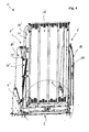
- FIG. 1 For example, a vehicle lift 1 is shown in perspective in a position referred to above as an intermediate position.
- a bottom plate 2 On a bottom plate 2, two mutually mirror-symmetrical stand 4, 4 'are fixed.
- the bottom plate 2 and the stand 4, 4 ' together form a vehicle-side holding section.
- a lifting device 6, 6' On the uprights 4, 4 'is in each case a lifting device 6, 6' is arranged, which is formed according to this embodiment as a parallelogram linkage.
- a support beam 10, 10 ' At the lifting device 6, 6 '(which is described in more detail below) is at the opposite end of the uprights 4, 4' a support beam 10, 10 'respectively.
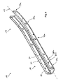
- the support beam 10, 10 ' (see also FIG. 6 ) has an upper portion 12, 12 'and a lower portion 14, 14'.
- the support beam 10, 10 ' is formed in one piece and bent in the upper portion 12, 12' along its longitudinal axis, as will also be described in more detail below.
- the support beam 10, 10 ' is formed as an aluminum profile with a substantially U-shaped cross-section.
- the lifting device 6, 6 ' (see FIG. 2 ) is designed as a parallelogram linkage. It has a first support arm 24 and a second support arm 26 arranged parallel thereto. Both support arms 24, 26 are connected to both the stator 4, and with the support beam 10 by means of the articulation points 30, 31, 32, 33 articulated. All articulation points 30, 31, 32, 33 are designed as pin plug connections, wherein at the articulation points 32, 33, which are arranged in the support beam 10, additionally here not shown sockets are inserted into the holes on the support beam 10 to reduce wear on the support beam 10.
- the two support arms 24, 26 are the same length and formed substantially identical.
- the articulation points 30, 31 on the stand 4 are selected such that the support arms 24, 26 forming the parallelogram can be brought into a first retracted position, in which the two support arms 24, 26 are arranged substantially vertically (cf. FIG. 4 ) and in a (not shown here) second position in which the support arms 24, 26 are arranged substantially horizontally.
- the articulation points 32, 33 on the support beam 10 are arranged correspondingly offset so as to allow the parallelogram of the lifting device 6.
- the upper portion 12 of the support beam 10 is formed bent so that the offset between the articulation points 32 and 33 is compensated.
- the lower portion 14 of the support beam 10 is formed substantially straight. This enables a compact design that also saves weight.
- a hydraulic cylinder 28 is provided for driving the lifting device 6.
- the hydraulic cylinder 28 is arranged diagonally in the parallelogram formed by the support arms 24, 26.
- the hydraulic cylinder 28 is connected on the one hand to the articulation point 30 and on the other hand to the articulation point 33.
- a mechanism 34 for pivoting the platform 16 is arranged on the vehicle lift 1.
- the mechanism 34 has a first leg 38 which is articulated to the support beam 10 and a second leg 36 which is connected by means of a hinge 40 with the first leg 38.
- a sliding shoe 41 is further arranged.
- the other end of the second leg 36 cooperates with the platform 16.
- a support 42 for supporting moments against the carrier spar 10 is arranged on the platform 16. At this support 42, the second leg 36 engages by being connected by means of a hinge 44 with this articulated.
- the corresponding hinge pieces 46, 47 of the second leg 36 which is designed as a push rod, are mounted relative to each other on this relatively.
- the sliding shoe 41 comes into contact with the second support arm 26, when the vehicle lift is moved to the first retracted position. In this case, a force acting on the second leg 36 on the support 42 and so on the platform 16, that it is pivoted about the pivot axis 18 around in the vertical.
- the shoe 41 loses from a certain extension point (for example, from the intermediate position as in FIG.
- an arm-shaped projection 48 is arranged on the support 42, which serves as a stop and a pivotal movement of the platform 16 relative to the support beam 10 limited by the projection 48 comes into contact with a reinforcing profile 50 (see FIG. 3 ).
- a screw 49 is arranged on the projection 48, which serves as an adjustable stop.
- the reinforcing profile 50 is screwed by means of two screw 51, 52 with the support beam 10.
- the shaft 19 which defines the pivot axis 18 is also received in the reinforcing profile 50 and firmly clamped in this with a clamping 54.
- the shaft 19 has a flattened region, so that the reinforcing profile 50 can engage in a positive engagement therewith.
- the first leg 38 of the mechanism 34 extends through the support spar 10, beyond the pivot bearing 45 addition.
- the support spar 10 also extending portion 39 of the handle 22 is attached. So this is when moving from the first to the second or from the second to the first position of the vehicle lift 1 automatically with movable and is pivoted in the first position vertically upwards.
- the handle 22 the in FIG. 3 has shown curved shape, this fits substantially to the bent portion 12 of the support beam 10 at.
- the vehicle lift 1 is particularly space-saving.
- FIG. 4 which illustrates the first position of the vehicle lift 1
- a side plate 60 is additionally arranged laterally on the lifting device 6. This serves on the one hand to reduce a risk of injury by preventing, for example, operators with fingers between the support arms 24, 26 advised.
- the side plate 60 has optical reasons. For illustration purposes it is related to the FIGS. 4 and 5 left carrier spar 10 'respectively omitted, so that the support arms 24', 26 'are visible. Only the right support bracket 10 is shown.
- the exact design of the support beam 10 is from the perspective view in FIG. 6 seen.
- the carrier spar 10 has a substantially elongated basic configuration.
- the upper portion 12 is bent, the lower portion 14 straight.
- the carrier spar 10 is integrally formed. In this embodiment, it is made of anodized aluminum.
- the support beam 10 has no welds or other joints. He is made by extrusion. Such an extrusion process has at least the steps extruding, cutting to length and bending.
- the carrier spar 10 is bent along its longitudinal axis 11.
- the longitudinal axis 11 is therefore curved.
- the carrier spar 10 has a substantially U-shaped profile. It has a back 70 and two side walls 72, 74, which are arranged substantially perpendicular to the back 70 and parallel to each other and thus form the two legs of the U-shaped cross section.
- Through-holes 33a, 34a, 45a, and 19a are formed in the side walls 72, 74 for receiving the articulated joints 33, 34, 45 and the pivot shaft 19 (see FIG. Figures 1-5 ).
- this through holes 33 a, 34 a, 45 a, 19 a jacks, not shown, are used, so that no or little wear on the aluminum support beam 10 occurs during operation.
- In the lower portion 14 further through holes 50a, 50b are provided for mounting the reinforcing profile 50 (see FIG. 9 ). Against the arranged in this section 14 between the two side walls 72, 74 reinforcing profile 50 moments by means of the support (see FIG. 8 ) supported.
- the support arms 24, 26 are formed with a substantially U-shaped cross-section. Exemplary is in FIG. 7 the cross section of the support arm 24 is shown. This has as well as the support beam 10, a back 80 and two side walls 82, 84 which are each substantially parallel to each other. In addition, a channel 86, 88 is respectively formed in the transition region between each side wall 82, 84 and the back 80. This is preferably introduced already during the extrusion of the support arm 24 or another manufacturing method. For example, cables can be passed through these channels 86, 88. Further, the channels 86, 88 act stiffening, so that the support arm 24 can absorb forces acting on the parallelogram, such as the slide shoe 41 acts on the support arm 26, better.
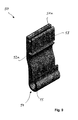
- the support 42 ( FIG. 8 ) has a main body 43 and extending therefrom arm-shaped projection 48 which serves as a stop. By means of the base body 43, the support 42 can be screwed against the platform 16. In the base body 43, a through hole 44a is provided for receiving the articulated connection 44 (see. FIG. 3 ).
- the support 42 is made as a freeform casting. As a result, this weight is optimized, so that the weight of the vehicle lift is reduced.
- the reinforcement profile (see FIG. 9 ) has two through holes 51 a, 52 a for receiving the screw 51, 52 with the support beam 10. These are slotted designed to simplify installation. In the area between these bores 51a, 52a, a contact surface 53 is formed, with which the stop 48 or the screw 49 of the support can come into contact. At the other end of the reinforcing profile 50, the clamp 54 for holding the shaft 19 (in FIG FIG. 9 not shown). At the clamping 54, a flattened portion 55 is provided which can cooperate with a flattened section on the shaft 19 in a form-fitting manner in order to fix it rotationally.
Landscapes
- Health & Medical Sciences (AREA)
- Public Health (AREA)
- Life Sciences & Earth Sciences (AREA)
- Animal Behavior & Ethology (AREA)
- General Health & Medical Sciences (AREA)
- Veterinary Medicine (AREA)
- Body Structure For Vehicles (AREA)
Abstract
Description
- Die Erfindung betrifft einen Fahrzeuglift für Lasten, insbesondere Rollstühle, welcher wenigstens in eine erste, eingefahrene Position und eine zweite, ausgefahrene Position verbringbar ist, mit wenigstens einem Tragholm, einer Plattform, die bewegbar an dem wenigstens einem Tragholm angelenkt ist, und wenigstens einer mit dem Tragholm gelenkig verbundenen Hubeinrichtung zum Heben und Absenken des Tragholms samt Plattform. Ferner betrifft die Erfindung einen Tragholm zur Verwendung in einem Fahrzeuglift sowie ein Herstellungsverfahren zur Herstellung eines derartigen Tragholms.
- An Fahrzeugen angebrachte Fahrzeuglifte sind seit Langem bekannt. Sie dienen dazu, Gegenstände oder Personen aus dem Inneren des Fahrzeugs nach Außen und zurück zu befördern, wenn zwischen dem Niveau des Fahrzeuginnenraums und der Stelle, an die die Gegenstände oder Personen gebracht werden sollen, ein Höhenunterschied besteht oder eine Lücke überbrückt werden muss. Eine wichtige Anwendung finden derartige Fahrzeuglifte in Fahrzeugen, in denen Rollstuhlfahrer transportiert werden. Ein solcher gattungsgemäßer Fahrzeuglift der hiesigen Anmelderin ist beispielsweise in
DE 203 09 868 U1 offenbart. - Bekannte Fahrzeuglifte weisen eine Plattform auf, die bewegbar an dem wenigstens einen Tragholm angelenkt ist und mittels einer Hubeinrichtung bewegt wird. In der Regel können wenigstens zwei Haupt-Positionen unterschieden werden. Die erste Position ist die eingefahrene Position, während der der Fahrzeuglift nicht verwendet wird. Die Plattform befindet sich dann in der Regel in einer vertikalen Lage, sodass der gesamte Fahrzeuglift einen möglichst geringen Raum- und Platzbedarf hat und während der Fahrt mit dem Fahrzeug nicht stört.
- In der zweiten Position ist der Fahrzeuglift ausgefahren und die Plattform befindet sich im Wesentlichen horizontal in Bodennähe, sodass beispielsweise ein Rollstuhlfahrer vom Boden leicht auf die Plattform fahren kann. Meist ist noch eine Zwischenposition vorgesehen, in der die Plattform etwa auf dem Niveau eines Fahrzeuginnenraums ist, sodass beispielsweise ein Rollstuhlfahrer von der Plattform in den Fahrzeuginnenraum fahren kann. Zwischen der Zwischenposition und der zweiten, ausgefahrenen Position wird die Plattform im Wesentlichen parallel zu sich selbst mittels der Hubeinrichtung abgesenkt.
- Insbesondere dem Tragholm eines derartigen Fahrzeuglifts kommt eine besondere Bedeutung zu. Dieser ist einerseits mit der Hubeinrichtung, die die Bewegung der Plattform verursacht, verbunden und andererseits ist die Plattform an dem Tragholm angelenkt. Folglich werden über den Tragholm sämtliche Kräfte und Momente von der Plattform ausgehend an das Fahrzeug übertragen. Daher muss ein derartiger Tragholm einerseits solche Kräfte aushalten und diesen widerstehen, andererseits muss der Tragholm so gestaltet sein, dass der Fahrzeuglift in der ersten Position möglichst platzsparend in dem Fahrzeug anordenbar ist. Zudem sollte der Tragholm leicht sein, um unnötiges zusätzliches Gewicht durch den Fahrzeuglift zu verhindern. Bisherige Tragholme bestehen dazu in der Regel aus einem Stahlträger, welcher eine Mehrzahl von Schweißnähten aufweist, sodass er in Tragholm-Form gebracht ist. Schweißnähte haben eine Vielzahl von Nachteilen. Einerseits bedeutet eine Schweißnaht stets einen oder mehrere zusätzliche Arbeitsschritte wie Schneiden, Vorbereiten, Schweißen, Reinigen etc. Andererseits stellen Schweißnähte in dynamisch und wechselnd belasteten Bauteilen meist besondere Schwachstellen dar.
- Aufgabe der vorliegenden Erfindung ist es daher, einen Fahrzeuglift, einen Tragholm und ein Herstellungsverfahren der eingangs genannten Art anzugeben, die bezüglich der oben genannten Probleme wenigstens teilweise verbessert sind.
- Diese Aufgabe wird bei einem Fahrzeuglift der eingangs genannten Art erfindungsgemäß mit den Mitteln des ersten Patentanspruchs gelöst, insbesondere also dadurch, dass der wenigstens eine Tragholm einstückig und wenigstens abschnittsweise entlang seiner Längsachse gebogen ausgebildet ist.
- Erfindungsgemäß wird dadurch der Vorteil erreicht, dass keinerlei Schweißnähte oder andere Fügeverfahrensschritte notwendig sind. Der wenigstens eine Tragholm ist vollständig einstückig ausgebildet. Dadurch ist einerseits die Herstellung wesentlich vereinfacht, andererseits entfallen kritische Verbindungsstellen, wodurch die Lebensdauer als auch die Sicherheit des Fahrzeuglifts verbessert ist. Indem der wenigstens eine Tragholm wenigstens abschnittsweise entlang seiner Längsachse gebogen ausgebildet ist, kann dieser besser zum Aufnehmen und Übertragen von Kräften und Momenten mit der Hubeinrichtung zusammenwirken. Ferner lässt sich der Fahrzeuglift aufgrund des gebogenen Abschnitts des wenigstens einen Tragholms platzsparender in der ersten Position in Fahrzeugen unterbringen.
- Indem der wenigstens eine Tragholm einstückig ausgebildet ist, kann dieser ebenfalls im Gewicht leichter ausfallen als herkömmliche Tragholme. Insbesondere wenn Schweißnähte vorgesehen sind, muss hierfür eine gewisse Materialstärke vorhanden sein. Bei einem erfindungsgemäßen Fahrzeuglift mit dem einstückigen Tragholm ist es möglich diesen Gewichtsoptimal zu gestalten. Ferner ist auch der optische Eindruck des Tragholms und somit des gesamten Fahrzeuglift wesentlich verbessert. Es entsteht ein sanft geschwungener, gefälliger und sportlicher Eindruck, der durch die einstückig gebogene Bauweise hervorgerufen wird.
- Der wenigstens eine Tragholm ist dabei vorzugsweise im Wesentlichen knickfrei. Der gebogene Abschnitt des Tragholms kann beispielsweise nur einen Teil des Tragholms einnehmen. In einer Alternative ist der Tragholm insgesamt gebogen ausgebildet. Erfindungsgemäß ist der Tragholm dabei entlang seiner Längsachse gebogen ausgebildet. Das heißt die Längsachse ist wenigstens abschnittsweise gekrümmt. Insbesondere sind bevorzugt zwei Tragholme bei dem Fahrzeuglift vorgesehen.
- In einer ersten bevorzugten Ausführungsform besteht der Tragholm aus Aluminium. Vorzugsweise ist der Tragholm als Aluminium-Strangpressprofil ausgebildet. Bevorzugt ist der Aluminium-Tragholm eloxiert. Indem der Tragholm aus Aluminium besteht, ist das Gewicht des Fahrzeuglifts wesentlich reduziert. Dies ist sehr vorteilhaft, da einerseits so die verbleibende Nutzlast eines Fahrzeugs, in das der Fahrzeuglift eingebaut wird, vergrößert ist und andererseits lässt sich ein Fahrzeug mit einem derartigen Fahrzeuglift energiesparender betreiben. Ist der Tragholm zusätzlich als Aluminium-Strangpressprofil ausgebildet, ist zusätzlich die Herstellung vereinfacht. Ein solches Profil kann beispielsweise endlos produziert werden und entsprechende Tragholme können anschließend abgelängt werden, wonach dann der gebogene Abschnitt in den Tragholm eingebracht wird. Hierdurch sind zusätzlich die Herstellungskosten reduziert.
- Vorzugsweise ist der Tragholm in einem oberen Abschnitt gebogen ausgebildet. Der Begriff "oben" bezieht sich hier auf eine übliche Einbausituation des Fahrzeuglifts. Vorzugsweise ist der Tragholm in dem oberen Abschnitt gelenkig mit der Hubeinrichtung verbunden. Indem der Tragholm in diesem oberen Abschnitt gebogen ausgebildet ist, ist das Zusammenwirken mit der Hubeinrichtung verbessert. Ein unterer Abschnitt kann demnach beispielsweise im Wesentlichen gerade ausgebildet sein. Indem der untere Abschnitt des Tragholms im Wesentlichen gerade ausgebildet ist, kann die Plattform in der zweiten, ausgefahrenen Position nah am Fahrzeug gehalten werden. Dies ist für die Sicherheit des Fahrzeuglifts vorteilhaft.
- In einer weiteren bevorzugten Ausführungsform ist der Tragholm als Profil ausgebildet, insbesondere in einem Querschnitt im Wesentlichen U-förmig ausgebildet. Indem der Tragholm als Profil, insbesondere U-förmiges Profil ausgebildet ist, ist einerseits die Steifigkeit des Tragholms vergrößert, sodass Kräfte und Momente besser übertragen werden können. Andererseits lässt sich eine Profilform, insbesondere im Wesentlichen U-förmige Profilform auf einfache Weise herstellen, beispielsweise mittels Strangpressen, sodass auch die Herstellung des Tragholms einfacher möglich ist.
- Vorzugsweise weist der gebogene Abschnitt des Tragholms einen Biegeradius zwischen 700mm und 1000mm, vorzugsweise etwa 820mm auf. Diese Angaben beziehen sich auf einen Innenradius, gemessen an einer Inneren Kante des Tragholms. Bei derartigen Biegeradien wird eine besonders gute Krafteinleitung erreicht, insbesondere wenn Anlenkpunkte der Hubeinrichtung an dem Tragholm auf einer Kreisbahn konzentrisch zu der durch den gebogenen Abschnitt beschriebenen Radius angeodnet sind. Zudem wird so der optische Eindruck des Fahrzeuglifts weiter verbessert.
- Gemäß einer bevorzugten Weiterbildung ist die Plattform um eine horizontale Schwenkachse schwenkbar an dem Tragholm angelenkt und die Hubeinrichtung zum Bewegen des Tragholms samt der Plattform senkrecht zu der Schwenkachse eingerichtet. Dies ist einerseits vorteilhaft, um einen möglichst platzsparenden Betrieb, wie er in engen Gassen und Parksituationen eines mit dem Fahrzeuglift ausgestatteten Fahrzeugs notwendig ist, zu ermöglichen, andererseits wird hierdurch auch die Konstruktion vereinfacht, sodass die Herstellung des Fahrzeuglifts einfacher ist und auch das Gewicht reduziert werden kann.
- Vorzugsweise weist die Hubeinrichtung ein Parallelogramm-Gestänge mit wenigstens zwei im Wesentlichen parallel zueinander angeordneten Tragarmen auf, die jeweils mit einem Ende an dem Tragholm und dem anderen Ende an einem fahrzeugseitigem Befestigungsabschnitt angelenkt sind, wobei die Tragarme vorzugsweise als Aluminium-Profile ausgebildet sind. Ein derartiges Parallelogramm-Gestänge ist grundsätzlich beispielsweise auch in der eingangs genannten
DE 203 09 868 U1 offenbart und lässt sich vorteilhaft zum Bewegen des Fahrzeuglifts einsetzen. Sind zwei Tragholme vorgsehen sind vorzugsweise ebenfalls zwei Parallelogramm-Gestänge vorgesehen. Indem die Tragarme aus Aluminiumprofilen gebildet sind, ist einerseits die Herstellung dieser vereinfacht, beispielsweise ist dies mittels Strangpressen, Walzen oder auch Tiefziehen möglich. Andererseits ist auch das Gewicht des Fahrzeuglifts weiter reduziert. Alternativ zu dem Parallelogramm-Gestänge könnten auch andere Hubeinrichtungen, wie beispielsweise rein hydraulische, pneumatische, elektrische oder auch andere mechanische Hubeinrichtungen, wie beispielsweise verschiedene Seilzüge und dergleichen zum Einsatz kommen. - Bevorzugt ist an den Tragarmen, vorzugsweise an einer Innenseite des Profils, wenigstens ein Kanal zum Durchführen von Leitungen angeformt. Ein derartiger Kanal wird vorzugsweise schon bei Herstellung der Tragarme an diesen angeformt, beispielsweise schon beim Strangpressen. Durch diesen Kanal sind Kabel, welche beispielsweise für Motoren, Beleuchtungsmittel und/oder eine Bedieneinrichtung an dem Fahrzeuglift notwendig sind, hindurchführbar. Diese Kabel sind durch den Kanal einerseits ortsfest gehalten, andererseits auch vor Beschädigungen geschützt. Dadurch ist die Sicherheit verbessert. Ferner ist auch der optische Eindruck verbessert, da keine Kabel sichtbar an einer Außenseite entlang geführt werden müssen.
- In einem weiteren Aspekt der Erfindung ist bei einem Fahrzeuglift der eingangs genannten Art oder nach einer der vorstehenden bevorzugten Ausführungsformen wenigstens eine Abstützung zum Abstützen von Momenten gegen den Tragholm an der Plattform angeordnet. Momente, die durch Lasten auf der Plattform um die gelenkige Verbindung zwischen Plattform und Tragholm herum hervorgerufen werden, müssen abgestützt werden. Dazu ist die Abstützung vorzugsweise fest an der Plattform angebracht und weist einen Kontaktabschnitt auf, mit dem er mit dem Tragholm in Kontakt kommt, um so Momente gegen diesen abzustützen. Die Abstützung ist vorzugsweise als Freiform- und/oder Gussteil ausgebildet. So wird auch das Gewicht des Fahrzeuglifts weiter reduziert.
- Vorzugsweise ist die Abstützung dazu vorgesehen eine Schwenkbewegung der Plattform relativ zu dem Tragholm zu begrenzen, indem ein an der Abstützung ausgebildeter Anschlag mit dem Tragholm in Kontakt kommt, wobei die Krafteinleitung in den Tragholm in einem mittleren Abschnitt des Tragholms, vorzugsweise im Wesentlichen mittig bezogen auf eine Richtung senkrecht zu der Längsachse des Tragholms stattfindet. Bevorzugt findet die Krafteinleitung im Bereich eines Rückens des im Querschnitt im Wesentlichen U-förmigen Tragholms statt, vorzugsweise zwischen den zwei Schenkeln des U-förmigen Tragholms und nicht an einem der Schenkel. Durch eine Krafteinleitung in den mittleren Bereich des Tragholms, bezogen auf eine Richtung senkrecht zu einer Längsachse, das heißt also bevorzugt im Wesentlichen in einer horizontalen Mitte des Tragholms, wird ein Tordieren des Tragholms vermieden. Der Anschlag der Abstützung ist vorzugsweise an einem Vorsprung ausgebildet, welcher sich von der Plattform aus armförmig in Richtung des Tragholms erstreckt. So ist auf vorteilhafte Weise das Einleiten der Kräfte in der Mitte des Tragholms möglich.
- Ferner ist bevorzugt, dass an dem Tragholm ein Verstärkungsprofil zum Zusammenwirken mit dem Anschlag der Abstützung angeordnet ist. Dies ist insbesondere vorteilhaft, wenn der Tragholm aus Aluminium ausgebildet ist. Aluminium ist ein Leichtbaumaterial mit einer geringen Dichte. Aufgrund dieser Eigenschaften können Schlag- und Abrasionsbeanspruchungen unter Umständen zu schnellerem Verschleiß führen. Daher ist vorzugsweise zur Schonung des Materials dieses Verstärkungsprofil an dem Tragholm angeordnet. Das Verstärkungsprofil kann beispielsweise in dem U-förmigen Bereich des Tragholms innerlich angeordnet sein. Vorzugsweise ist das Verstärkungsprofil mittels einer Schraubverbindung mit dem Tragholm verbunden. Das Verstärkungsprofil ist vorzugsweise als Verschleißteil vorgesehen. So ist im Verschleißfall allein das Verstärkungsprofil auszutauschen, während der Tragholm intakt bleibt. Dadurch sind einerseits die Kosten reduziert, andererseits ist auch eine Reparatur bzw. Wartung des Fahrzeuglifts vereinfacht. Das Verstärkungsprofil besteht vorzugsweise aus Aluminium. Alternativ besteht das Verstärkungsprofil aus einem anderen Metall- oder Kunststoffwerkstoff. Weiterhin ist bevorzugt, dass ein Mechanismus zum Schwenken der Plattform vorgesehen ist, der an der Abstützung und/oder an der Plattform angreift. Der Mechanismus ist dafür vorgesehen, die Plattform von der ersten, eingefahrenen Position, in der die Plattform im Wesentlichen vertikal ausgerichtet ist, in die Horizontale zu schwenken, in der die Plattform in der zweiten, ausgefahrenen Position angeordnet ist. Folglich ist die Hubeinrichtung zum Anheben und Absenken vorgesehen, und der Mechanismus nur zum Schwenken der Plattform.
- Vorzugsweise weist dieser Mechanismus zum Schwenken der Plattform einen Kniehebel mit einem ersten Schenkel und einen mit diesem kniegelenkig verbundenen zweiten Schenkel auf, wobei der erste Schenkel an dem Tragholm und der zweite Schenkel an einer Abstützung angelenkt ist. Ein solcher Kniehebel ist eine besonders einfache Möglichkeit die Plattform zu schwenken. Beispielsweise kann beim Verbringen des Fahrzeuglifts von der ersten in die zweite Position das Kniegelenk, an welchem vorzugsweise ein Gleitschuh vorgesehen ist, in Kontakt mit einem der Tragarme des Parallelogramm-Gestänges kommen und so die Plattform verschwenken.
- Besonders bevorzugt ist der zweite Schenkel als Schubstange ausgebildet, wobei an beiden Enden Gelenkelemente relativ zu der Schubstange einstellbar angeordnet sind. Beispielsweise sind die Gelenkelemente, wobei ein Gelenkelement mit einen Teil des Kniegelenks bildet und das zweite Gelenkelement an der Plattform und/oder an der Abstützung angelenkt ist, mittels gegenläufigen Gewinden mit der Schubstange verbunden. So sind die beiden Gelenkelemente etwa mittels Drehen der Schubstange aufeinander zu bzw. voneinander weg bewegbar und so relativ zueinander einstellbar. Dadurch ist ein Schwenkwinkel der Plattform beim Verbringen von der ersten Position in die zweite Position einstellbar. Je nach Fahrzeugtyp und Einbausituation kann dieser Winkel variieren, sodass es vorteilhaft ist, diesen Winkel auf einfache Art und Weise einstellbar auszubilden.
- Gemäß einer weiteren bevorzugten Ausführungsform sind an der Plattform zwei Seitenbleche angeordnet, welche jeweils eine Prägung aufweisen. Seitenbleche dienen einerseits zur seitlichen Führung von beispielweise auf die Plattform fahrenden Rollstühlen und erhöhen so einerseits die Sicherheit. Andererseits dienen sie auch der Stabilisierung der Plattform, sodass diese bei Belastung nicht durchbiegt. Die Seitenbleche sind dazu vorzugsweise im Wesentlichen senkrecht zu der durch die Plattform gebildeten Ebene angeordnet. Indem Prägungen in den Seitenblechen eingebracht sind, ist die Steifigkeit dieser erhöht, sodass die Seitenbleche und die Plattform selbst mit geringeren Materialstärken realisiert werden kann, wodurch das Gewicht des Fahrzeuglifts verringert ist. Die Prägung ist vorzugsweise entlang einer Längsachse der Seitenbleche eingebracht.
- Gemäß einem weiteren Aspekt der Erfindung wird die eingangs genannte Aufgabe durch einen Tragholm zur Verwendung in einem Fahrzeuglift gelöst, indem der Fahrzeuglift nach einem der vorstehenden Ansprüche ausgebildet ist, wobei der Tragholm als einstückiges gebogenes Aluminiumprofil ausgebildet ist.
- Gemäß einem weiteren Aspekt der Erfindung wird die eingangs genannte Aufgabe gelöst durch ein Herstellungsverfahren für einen Tragholm zur Verwendung in einem Fahrzeuglift nach einem der vorstehenden Ansprüche, wobei das Verfahren die Schritte aufweist: Strangpressen, insbesondere Aluminium-Strangpressen eines im Wesentlichen U-förmigen Profils; und Biegen des Profils wenigstens abschnittsweise entlang seiner Längsachse.
- Es soll verstanden werden, dass der Tragholm gemäß dem weiteren Aspekt und das Herstellungsverfahren gemäß dem weiteren Aspekt sowie der Fahrzeuglift ähnliche und identische bevorzugte Weiterbildungen und Vorteile aufweisen, sodass auf das oben Stehende verwiesen wird.
- Im Folgenden wird die Erfindung anhand eines Ausführungsbeispiels unter Bezugnahme auf die beiliegenden Figuren näher erläutert. Hierbei zeigen:
- Figur 1
- eine perspektivische Ansicht eines Fahrzeuglifts in der Zwischenposition;
- Figur 2
- eine Seitenansicht des Fahrzeuglifts in der Zwischenposition;
- Figur 3
- eine Schnittdarstellung durch den Fahrzeuglift in der Zwischenposition;
- Figur 4
- eine perspektivische Ansicht des Fahrzeuglifts in der ersten Position;
- Figur 5
- eine Frontalansicht des Fahrzeuglifts in der ersten Position;
- Figur 6
- einen Tragholm in einer perspektivischen Ansicht;
- Figur 7
- einen Schnitt durch einen Tragarm;
- Figur 8
- eine perspektivische Ansicht einer Abstützung; und
- Figur 9
- eine perspektivische Ansicht eines Verstärkungsprofils.
- In
Figur 1 ist ein Fahrzeuglift 1 in perspektivischer Darstellung in einer Position gezeigt, die vorstehend als Zwischenposition bezeichnet ist. Auf einer Bodenplatte 2 sind zwei zueinander spiegelsymmetrische Ständer 4, 4' befestigt. Die Bodenplatte 2 sowie die Ständer 4, 4' bilden gemeinsam einen fahrzeugseitigen Halteabschnitt. An den Ständern 4, 4' ist jeweils eine Hubeinrichtung 6, 6' angeordnet, die gemäß diesem Ausführungsbeispiel als Parallelogramm-Gestänge ausgebildet ist. An der Hubeinrichtung 6, 6' (die weiter unten detaillierter beschrieben ist) ist an dem den Ständern 4, 4' gegenüberliegenden Ende jeweils ein Tragholm 10, 10' angeordnet. Der Tragholm 10, 10' (vgl. auchFigur 6 ) weist einen oberen Abschnitt 12, 12' und einen unteren Abschnitt 14, 14' auf. Mit dem oberen Abschnitt 12, 12' ist der Tragholm 10, 10' mit der Hubeinrichtung 6, 6' verbunden. Am unteren Ende 14, 14' ist an dem Tragholm 10, 10' eine Plattform 16 mittels einer Welle 19 schwenkbar um die Schwenkachse 18 angelenkt. An der Plattform 16 sind an den seitlichen Rändern jeweils Seitenbleche 20, 20' angeordnet, wobei entlang der Längsachse eine Prägung 21 (nur bei einem Seitenblech gezeigt) eingebracht ist. An dem Tragholm 10 ist ferner ein Handgriff 22 angeordnet. An diesem Handgriff 22 kann sich ein Rollstuhlfahrer, der mittels des Fahrzeuglifts 1 transportiert wird, während des Transports festhalten. - Der Tragholm 10, 10' ist einstückig und in dem oberen Abschnitt 12, 12' entlang seiner Längsachse gebogen ausgebildet, wie dies auch weiter unten noch detaillierter beschrieben werden wird. Der Tragholm 10, 10' ist als Aluminium-Profil mit im Wesentlichen U-förmigem Querschnitt ausgebildet.
- Die Hubeinrichtung 6, 6' (siehe
Figur 2 ) ist als Parallelogramm-Gestänge ausgebildet. Sie weist einen ersten Tragarm 24 und einen parallel dazu angeordneten zweiten Tragarm 26 auf. Beide Tragarme 24, 26 sind sowohl mit dem Ständer 4, als auch mit dem Tragholm 10 mittels der Anlenkpunkte 30, 31, 32, 33 gelenkig verbunden. Alle Anlenkpunkte 30, 31, 32, 33 sind als Bolzensteckverbindungen ausgebildet, wobei an den Anlenkpunkten 32, 33, welche in dem Tragholm 10 angeordnet sind, zusätzlich hier nicht gezeigte Buchsen in die Bohrungen an dem Tragholm 10 eingebracht sind, um Verschleiß an dem Tragholm 10 zu verringern. - Die beiden Tragarme 24, 26 sind gleich lang und im Wesentlichen identisch ausgebildet. Die Anlenkpunkte 30, 31 an dem Ständer 4 sind derart gewählt, dass die das Parallelogramm bildenden Tragarme 24, 26 in eine erste eingefahrene Position verbringbar sind, in der die beiden Tragarme 24, 26 im Wesentlichen senkrecht angeordnet sind (vgl.
Figur 4 ) sowie in eine (hier nicht gezeigte) zweite Position, in der die Tragarme 24, 26 im Wesentlichen horizontal angeordnet sind. Die Anlenkpunkte 32, 33 am Tragholm 10 sind entsprechend versetzt angeordnet, um so das Parallelogramm der Hubeinrichtung 6 zu ermöglichen. Der obere Abschnitt 12 des Tragholms 10 ist derart gebogen ausgebildet, dass der Versatz zwischen den Anlenkpunkten 32 und 33 ausgeglichen wird. Der untere Abschnitt 14 des Tragholms 10 ist im Wesentlichen gerade ausgebildet. So wird eine kompakte Bauform ermöglicht, die zudem gewichtssparend ist. - Zum Antreiben der Hubeinrichtung 6 ist ein Hydraulikzylinder 28 vorgesehen. Der Hydraulikzylinder 28 ist diagonal in dem durch die Tragarme 24, 26 gebildeten Parallelogramm angeordnet. Dazu ist der Hydraulikzylinder 28 einerseits mit dem Anlenkpunkt 30 und andererseits mit dem Anlenkpunkt 33 verbunden. Beim Ausfahren des Hydraulikzylinders 28 wird demnach der Fahrzeuglift in die erste Position verbracht, entsprechend beim Einfahren des Hydraulikzylinders 28 in die zweite Position, wie leicht aus
Figur 2 ersichtlich ist. - Ferner ist an dem Fahrzeuglift 1 ein Mechanismus 34 zum Schwenken der Plattform 16 angeordnet. Der Mechanismus 34 weist einen ersten Schenkel 38 auf, der an dem Tragholm 10 angelenkt ist und einen zweiten Schenkel 36, der mittels eines Gelenks 40 mit dem ersten Schenkel 38 verbunden ist. An diesem Knie-Gelenk 40 ist ferner ein Gleitschuh 41 angeordnet. Das andere Ende des zweiten Schenkels 36 wirkt mit der Plattform 16 zusammen. Dazu ist an der Plattform 16 eine Abstützung 42 zum Abstützen von Momenten gegen den Tragholm 10 angeordnet. An dieser Abstützung 42 greift der zweite Schenkel 36 an, indem er mittels eines Gelenks 44 mit diesem gelenkig verbunden ist.
- Die entsprechenden Gelenkstücke 46, 47 des zweiten Schenkels 36, der als Schubstange ausgebildet ist, sind relativ verschiebbar zueinander an diesem befestigt. Wie leicht aus
Figur 2 ersichtlich, kommt der Gleitschuh 41 in Kontakt mit dem zweiten Tragarm 26, wenn der Fahrzeuglift in die erste eingefahrene Position verbracht wird. Dabei wirkt eine Kraft derart über den zweiten Schenkel 36 auf die Abstützung 42 und so auf die Plattform 16, dass diese um die Schwenkachse 18 herum in die Vertikale geschwenkt wird. Andersherum, beim Ausfahren des Fahrzeuglifts 1, verliert der Gleitschuh 41 ab einem bestimmten Ausfahrpunkt (beispielsweise ab der Zwischenposition wie inFigur 2 gezeigt) den Kontakt mit dem zweiten Tragarm 26. Um dann ein weiteres Absinken der Plattform 16 zu verhindern, ist an der Abstützung 42 ein armförmiger Vorsprung 48 angeordnet, der als Anschlag dient und eine Schwenkbewegung der Plattform 16 relativ zu dem Tragholm 10 begrenzt, indem der Vorsprung 48 in Kontakt kommt mit einem Verstärkungsprofil 50 (sieheFigur 3 ). Wie insbesondere aus dem Detail inFigur 3 ersichtlich, ist an dem Vorsprung 48 eine Schraube 49 angeordnet, die als verstellbarer Anschlag dient. Dadurch ist der Schwenkwinkel, ab dem die Verschwenkung der Plattform 16 relativ zu dem Tragholm 10 begrenzt ist, einstellbar. Das Verstärkungsprofil 50 ist dazu mittels zweier Schraubverbindungen 51, 52 mit dem Tragholm 10 verschraubt. Die Welle 19, die die Schwenkachse 18 definiert ist ebenfalls in dem Verstärkungsprofil 50 aufgenommen und in diesem mit einer Klemmung 54 fest verspannt. Dazu weist die Welle 19 einen abgeflachten Bereich auf, sodass das Verstärkungsprofil 50 formschlüssig an dieser angreifen kann. - Wie insbesondere aus
Figur 3 ersichtlich, erstreckt sich der erste Schenkel 38 des Mechanismus 34 durch den Tragholm 10 hindurch, über die Schwenklagerung 45 hinaus. An diesem sich über den Tragholm 10 hinaus erstreckenden Abschnitt 39 ist der Handgriff 22 befestigt. So ist dieser beim Verbringen von der ersten in die zweite bzw. von der zweiten in die erste Position des Fahrzeuglifts 1 selbsttätig mit bewegbar und befindet sich in der ersten Position vertikal nach oben geschwenkt. Indem der Handgriff 22 die inFigur 3 gezeigte gebogene Form hat, fügt sich dieser im Wesentlichen an den gebogenen Abschnitt 12 des Tragholms 10 an. Dadurch ist der Fahrzeuglift 1 besonders platzsparend. - In
Figur 4 , die die erste Position des Fahrzeuglifts 1 illustriert, ist zusätzlich seitlich an der Hubeinrichtung 6 ein Seitenblech 60 angeordnet. Dies dient einerseits der Verringerung eines Verletzungsrisikos, indem verhindert wird dass beispielsweise Bediener mit Fingern zwischen die Tragarme 24, 26 geraten. Andererseits hat das Seitenblech 60 optische Gründe. Zu Illustrationszwecken ist der bezogen auf dieFiguren 4 und5 linke Tragholm 10' jeweils weggelassen, sodass die Tragarme 24', 26' sichtbar sind. Nur der rechte Trag holm 10 ist dargestellt. - Die genaue Gestaltung des Tragholms 10 ist aus der perspektivischen Ansicht in
Figur 6 ersichtlich. Der Tragholm 10 weist eine im Wesentlichen längliche Grundkonfiguration auf. Der obere Abschnitt 12 ist gebogen ausgebildet, der untere Abschnitt 14 gerade. Insgesamt ist der Tragholm 10 einstückig ausgebildet. Gemäß diesem Ausführungsbeispiel ist er aus eloxiertem Aluminium hergestellt. Wie ausFigur 6 ersichtlich, weist der Tragholm 10 keinerlei Schweißnähte oder andere Verbindungsstellen auf. Er ist durch Strangpressen hergestellt. Ein solches Strangpressverfahren weist wenigstens die Schritte Strangpressen, Ablängen und Biegen auf. - Der Tragholm 10 ist entlang seiner Längsachse 11 gebogen. Die Längsachse 11 ist demnach gekrümmt.
- Der Tragholm 10 weist ein im Wesentlichen U-förmiges Profil auf. Er hat einen Rücken 70 sowie zwei Seitenwände 72, 74, die im Wesentlichen senkrecht zum Rücken 70 und parallel zueinander angeordnet sind und so die zwei Schenkel des U-förmigen Querschnitts bilden. In die Seitenwände 72, 74 sind Durchgangsbohrungen 33a, 34a, 45a und 19a eingebracht, zum Aufnehmen der gelenkigen Verbindungen 33, 34, 45 und der Schwenkwelle 19 (vgl.
Figuren 1-5 ). In diese Durchgangsbohrungen 33a, 34a, 45a, 19a werden nicht gezeigte Buchsen eingesetzt, sodass kein bzw. nur wenig Verschleiß an dem Aluminium-Tragholm 10 im Betrieb auftritt. In dem unteren Abschnitt 14 sind weitere Durchgangsbohrungen 50a, 50b vorgesehen, zur Montage des Verstärkungsprofils 50 (sieheFigur 9 ). Gegen das in diesem Abschnitt 14 zwischen den beiden Seitenwänden 72, 74 angeordnete Verstärkungsprofil 50 werden Momente mittels der Abstützung (sieheFigur 8 ) abgestützt. - Auch die Tragarme 24, 26 sind mit im Wesentlichen U-förmigem Querschnitt ausgebildet. Exemplarisch ist in
Figur 7 der Querschnitt des Tragarms 24 dargestellt. Dieser weist ebenso wie der Tragholm 10 einen Rücken 80 und zwei Seitenwände 82, 84 auf, die jeweils im Wesentlichen parallel zueinander sind. Zusätzlich ist jeweils im Übergangsbereich zwischen jeder Seitenwand 82, 84 und dem Rücken 80 ein Kanal 86, 88 ausgebildet. Dieser wird vorzugsweise schon beim Strangpressen des Tragarms 24 oder einem anderen Herstellungsverfahren mit eingebracht. Durch diese Kanäle 86, 88 sind beispielsweise Kabel hindurch führbar. Ferner wirken die Kanäle 86, 88 versteifend, sodass der Tragarm 24 Kräfte, welche auf das Parallelogramm wirken, wie etwa der Gleitschuh 41 auf den Tragarm 26 wirkt, besser aufnehmen kann. - Die Abstützung 42 (
Figur 8 ) weist einen Grundkörper 43 und einen sich von diesem erstreckenden armförmigen Vorsprung 48 auf, der als Anschlag dient. Mittels des Grundkörpers 43 ist die Abstützung 42 gegen die Plattform 16 verschraubbar. In dem Grundkörper 43 ist eine Durchgangsbohrung 44a vorgesehen zur Aufnahme der gelenkigen Verbindung 44 (vgl.Figur 3 ). Die Abstützung 42 ist als Freiformgussteil hergestellt. Dadurch ist dieser gewichtsoptimal gestaltet, sodass das Gewicht des Fahrzeuglifts verringert ist. - Das Verstärkungsprofil (siehe
Figur 9 ) weist zwei Durchgangsbohrungen 51a, 52a zur Aufnahme der Verschraubung 51, 52 mit dem Tragholm 10 auf. Diese sind geschlitzt ausgebildet, um die Montage zu vereinfachen. In dem Bereich zwischen diesen Bohrungen 51a, 52a ist eine Kontaktfläche 53 ausgebildet, mit der der Anschlag 48 bzw. die Schraube 49 der Abstützung in Kontakt kommen kann. An dem anderen Ende des Verstärkungsprofils 50 ist die Klemmung 54 zum Halten der Welle 19 (inFigur 9 nicht gezeigt) ausgebildet. An der Klemmung 54 ist ein abgeflachter Abschnitt 55 vorgesehen, der formschlüssig mit einem abgeflachten Abschnitt an der Welle 19 zusammenwirken kann, um diese rotatorisch zu fixieren.
Claims (19)
- Fahrzeuglift (1) für Lasten, insbesondere Rollstühle, welcher wenigstens in eine erste, eingefahrene Position und eine zweite, ausgefahrene Position verbringbar ist, mit wenigstens einem Tragholm (10, 10'),
einer Plattform (16), die bewegbar an dem wenigstens einen Tragholm (10, 10') angelenkt ist, und
wenigstens einer mit dem Tragholm (10, 10') gelenkig verbundenen Hubeinrichtung (6, 6') zum Heben und Absenken des Tragholms (10, 10') samt Plattform (16),
dadurch gekennzeichnet, dass der wenigstens eine Tragholm (10, 10') einstückig und wenigstens abschnittsweise entlang seiner Längsachse (11) gebogen ausgebildet ist. - Fahrzeuglift nach Anspruch 1,
dadurch gekennzeichnet, dass der Tragholm (10, 10') aus Aluminium besteht. - Fahrzeuglift nach einem der vorstehenden Ansprüche,
dadurch gekennzeichnet, dass der Tragholm (10, 10') keine Schweißnähte aufweist. - Fahrzeuglift nach einem der vorstehenden Ansprüche,
dadurch gekennzeichnet, dass der Tragholm (10, 10') in einem oberen Abschnitt (12, 12') gebogen ausgebildet ist. - Fahrzeuglift nach einem der vorstehenden Ansprüche,
dadurch gekennzeichnet, dass der Tragholm (10, 10') in dem mit der Hubeinrichtung (6, 6') gelenkig verbundenen Abschnitt (12, 12') gebogen ausgebildet ist. - Fahrzeuglift nach einem der vorstehenden Ansprüche,
dadurch gekennzeichnet, dass der Tragholm (10, 10') als Profil ausgebildet ist, insbesondere in einem Querschnitt im Wesentlichen U-förmig ausgebildet ist. - Fahrzeuglift nach einem der vorstehenden Ansprüche,
dadurch gekennzeichnet, dass der gebogene Abschnitt (12, 12') des Tragholms (10, 10') einen Biegeradius zwischen 700mm und 1000mm, vorzugsweise 820mm aufweist. - Fahrzeuglift nach einem der vorstehenden Ansprüche,
dadurch gekennzeichnet, dass die Plattform (16) um eine horizontale Schwenkachse (18) schwenkbar an dem Tragholm (10, 10') angelenkt ist und die Hubeinrichtung (6, 6') zum Bewegen des Tragholms (10, 10') samt der Plattform (16) senkrecht zu der Schwenkachse (18) eingerichtet ist. - Fahrzeuglift nach einem der vorstehenden Ansprüche,
dadurch gekennzeichnet, dass die Hubeinrichtung (6, 6') ein Parallelogramm-Gestänge mit wenigstens zwei im Wesentlichen parallel zueinander angeordneten Tragarmen (24, 26) aufweist, die jeweils mit einem Ende an dem Tragholm (10, 10') und dem anderen Ende an einem fahrzeugseitigen Befestigungsabschnitt (2, 4, 4') angelenkt sind, wobei die Tragarme (24, 26) vorzugsweise als Aluminium-Profile ausgebildet sind. - Fahrzeuglift nach Anspruch 9,
dadurch gekennzeichnet, dass an den Tragarmen (24, 26), vorzugsweise an einer Innenseite des Profils, wenigstens ein Kanal (86, 88) zum Durchführen von Leitungen angeformt ist. - Fahrzeuglift nach dem Oberbegriff von Anspruch 1 oder einem der vorstehenden Ansprüche,
gekennzeichnet durch wenigstens eine an der Plattform (16) angeordnete Abstützung (42) zum Abstützen von Momenten gegen den Tragholm (10, 10'). - Fahrzeuglift nach Anspruch 11,
dadurch gekennzeichnet, dass die Abstützung (42) dazu vorgesehen ist eine Schwenkbewegung der Plattform (16) relativ zu dem Tragholm (10, 10') zu begrenzen, indem ein an der Abstützung (42) ausgebildeter Anschlag (48) mit dem Tragholm (10, 10') in Kontakt kommt, wobei die Krafteinleitung in den Tragholm im Wesentlichen mittig bezogen auf eine Richtung senkrecht zu einer Längsachse (11) des Tragholms (10, 10') stattfindet. - Fahrzeuglift nach Anspruch 12,
dadurch gekennzeichnet, dass an dem Tragholm (10, 10') ein Verstärkungsprofil (50) angeordnet ist, zum Zusammenwirken mit dem Anschlag (48) der Abstützung (42). - Fahrzeuglift nach einem der Ansprüche 11 bis 13,
gekennzeichnet durch einen Mechanismus (34) zum Schwenken der Plattform (16), der an der Abstützung (42) und/oder an der Plattform (16) angreift. - Fahrzeuglift nach Anspruch 14,
dadurch gekennzeichnet, dass der Mechanismus (34) zum Schwenken der Plattform (16) einen Kniehebel mit einem ersten Schenkel (38) und einem mit diesem kniegelenkig verbundenen zweiten Schenkel (36) aufweist, wobei der erste Schenkel (38) an dem Tragholm (10, 10') und der zweite Schenkel (36) an der Abstützung (42) angelenkt ist. - Fahrzeuglift nach Anspruch 15,
dadurch gekennzeichnet, dass der zweite Schenkel (36) als Schubstange ausgebildet ist, wobei an beiden Enden Gelenkelemente (46, 47) relativ zu der Schubstange einstellbar angeordnet sind. - Fahrzeuglift nach einem der vorstehenden Ansprüche,
gekennzeichnet durch zwei an der Plattform (16) angeordnete Seitenbleche (20, 20'), welche eine Prägung (21) aufweisen. - Tragholm (10, 10') zur Verwendung in einem Fahrzeuglift (1) nach einem der vorstehenden Ansprüche, wobei der Tragholm (10, 10') als einstückiges gebogenes Aluminiumprofil ausgebildet ist.
- Herstellungsverfahren für einen Tragholm (10, 10') zur Verwendung in einem Fahrzeuglift (1) nach einem der vorstehenden Ansprüche, mit den Schritten:- Strangpressen, insbesondere Aluminium-Strangpressen eines im Wesentlichen U-förmigen Profils; und- Biegen des Profils wenigstens abschnittsweise entlang seiner Längsachse (11).
Applications Claiming Priority (2)
| Application Number | Priority Date | Filing Date | Title |
|---|---|---|---|
| DE202012002833U DE202012002833U1 (de) | 2012-03-21 | 2012-03-21 | Fahrzeuglift |
| US13/538,060 US9814635B2 (en) | 2012-03-21 | 2012-06-29 | Vehicle lift |
Publications (2)
| Publication Number | Publication Date |
|---|---|
| EP2641576A1 true EP2641576A1 (de) | 2013-09-25 |
| EP2641576B1 EP2641576B1 (de) | 2015-04-22 |
Family
ID=47913195
Family Applications (1)
| Application Number | Title | Priority Date | Filing Date |
|---|---|---|---|
| EP20130160454 Active EP2641576B1 (de) | 2012-03-21 | 2013-03-21 | Fahrzeuglift |
Country Status (1)
| Country | Link |
|---|---|
| EP (1) | EP2641576B1 (de) |
Cited By (3)
| Publication number | Priority date | Publication date | Assignee | Title |
|---|---|---|---|---|
| EP2818148A1 (de) | 2013-06-24 | 2014-12-31 | Autolift S.r.l. | Rollstuhlaufzug |
| CN107472330A (zh) * | 2017-09-28 | 2017-12-15 | 辽宁工业大学 | 一种多功能折叠式家用便利车 |
| DE202023100421U1 (de) | 2023-01-30 | 2023-02-09 | Bruns Holding Gmbh & Co. Kg | Lift-Vorrichtung |
Families Citing this family (1)
| Publication number | Priority date | Publication date | Assignee | Title |
|---|---|---|---|---|
| GB2634254A (en) * | 2023-10-03 | 2025-04-09 | Passenger Lift Solutions Ltd | Lifts |
Citations (3)
| Publication number | Priority date | Publication date | Assignee | Title |
|---|---|---|---|---|
| JP2003341408A (ja) * | 2002-05-27 | 2003-12-03 | Araco Corp | 車両用昇降装置 |
| DE20309868U1 (de) | 2003-06-25 | 2004-11-04 | Apener Maschinenbau und Förderanlagen Gustav Bruns GmbH & Co KG | Fahrzeuglift für Lasten, insbesondere für Rollstühle |
| DE69933332T2 (de) * | 1998-05-01 | 2007-05-03 | The Braun Corp., Winamac | Rollstuhllift für Fahrzeuge |
Family Cites Families (5)
| Publication number | Priority date | Publication date | Assignee | Title |
|---|---|---|---|---|
| DE8524319U1 (de) | 1985-08-24 | 1985-10-10 | Röhm GmbH, 6100 Darmstadt | Verglasungssprosse |
| US5230522A (en) * | 1991-06-25 | 1993-07-27 | Gehlsen Paul R | Apparatus for moving a wheelchair over stepped obstacles |
| US5234311A (en) | 1991-07-17 | 1993-08-10 | Ricon Corporation | Wheelchair lift with adjustable posts |
| DE20318186U1 (de) * | 2003-11-25 | 2004-07-22 | Gebr. Bode Gmbh & Co. Kg | Einstiegsrampe für Kraftfahrzeuge, insbesondere Kraftfahrzeuge des öffentlichen Personennahverkehrs |
| NO20044636L (no) | 2004-10-27 | 2006-04-28 | Raufosstechnology As | Kontrollarm og fremgangsmate for fremstilling av denne |
-
2013
- 2013-03-21 EP EP20130160454 patent/EP2641576B1/de active Active
Patent Citations (3)
| Publication number | Priority date | Publication date | Assignee | Title |
|---|---|---|---|---|
| DE69933332T2 (de) * | 1998-05-01 | 2007-05-03 | The Braun Corp., Winamac | Rollstuhllift für Fahrzeuge |
| JP2003341408A (ja) * | 2002-05-27 | 2003-12-03 | Araco Corp | 車両用昇降装置 |
| DE20309868U1 (de) | 2003-06-25 | 2004-11-04 | Apener Maschinenbau und Förderanlagen Gustav Bruns GmbH & Co KG | Fahrzeuglift für Lasten, insbesondere für Rollstühle |
Cited By (5)
| Publication number | Priority date | Publication date | Assignee | Title |
|---|---|---|---|---|
| EP2818148A1 (de) | 2013-06-24 | 2014-12-31 | Autolift S.r.l. | Rollstuhlaufzug |
| US9974702B2 (en) | 2013-06-24 | 2018-05-22 | Autolift S.R.L. | Wheelchair lift |
| CN107472330A (zh) * | 2017-09-28 | 2017-12-15 | 辽宁工业大学 | 一种多功能折叠式家用便利车 |
| DE202023100421U1 (de) | 2023-01-30 | 2023-02-09 | Bruns Holding Gmbh & Co. Kg | Lift-Vorrichtung |
| EP4417175A2 (de) | 2023-01-30 | 2024-08-21 | Bruns Holding GmbH & Co. KG | Lift-vorrichtung |
Also Published As
| Publication number | Publication date |
|---|---|
| EP2641576B1 (de) | 2015-04-22 |
Similar Documents
| Publication | Publication Date | Title |
|---|---|---|
| DE202012002833U1 (de) | Fahrzeuglift | |
| EP0983897B1 (de) | Hebevorrichtung | |
| EP0983196B1 (de) | Schleppfahrzeug für flugzeuge | |
| DE69022403T2 (de) | Gestell für Fahrzeuge. | |
| DE202012002832U1 (de) | Fahrzeuglift mit Vorspanneinrichtung | |
| EP2016017B1 (de) | Tragarm für eine hebebühne | |
| DE8605875U1 (de) | Montageeinrichtung für Karosserieteile von Kraftfahrzeugen | |
| EP3549900A1 (de) | Hebebühne für kraftfahrzeuge | |
| EP2641576B1 (de) | Fahrzeuglift | |
| EP0785167B1 (de) | Seitenschiebereinrichtung für Flurförderzeuge | |
| EP3009283B1 (de) | Antriebssystem für ein bewegliches dachteil eines kraftfahrzeug-dachmoduls | |
| DE3813049A1 (de) | Gleitschuh, insbesondere fuer fahrzeugschiebedaecher | |
| EP2995526A1 (de) | Schienenfahrzeug und kupplungsanordnung für das schienenfahrzeug sowie verfahren zum koppeln des schienenfahrzeuges mit einem zweiten schienenfahrzeug | |
| EP3247614B1 (de) | Fahrzeug, insbesondere kraftfahrzeug, mit einer fahrzeugheckklappe | |
| DE102008056542B4 (de) | Stromabnehmer für ein Schienenfahrzeug | |
| EP2534086B1 (de) | Aufstellvorrichtung für scherenhebebühnen | |
| WO1998043856A2 (de) | Hebevorrichtung für kraftfahrzeuge und fahrzeuganhänger, insbesondere ein wagenheber | |
| DE102007059065A1 (de) | Gabelstapler mit einem als Torsionsstütze vorgesehenen Fahrerschutzdach | |
| EP2705971A2 (de) | Stromabnehmer | |
| DE102011085177A1 (de) | Antriebssystem für ein KFZ-Dachsystem | |
| DE102011050753A1 (de) | Sitzvorrichtung für Montage- oder Fertigungsstraßen | |
| EP1052139A2 (de) | Sitzschienenpaar für Fahrzeugsitz | |
| DE19934993B4 (de) | Radarme für Gabelniederhubwagen | |
| EP2066538B1 (de) | Waschportal und verfahren zur montage eines waschportals | |
| DE19853536A1 (de) | Kabine für Frontsitz-Flurförderzeuge |
Legal Events
| Date | Code | Title | Description |
|---|---|---|---|
| PUAI | Public reference made under article 153(3) epc to a published international application that has entered the european phase |
Free format text: ORIGINAL CODE: 0009012 |
|
| AK | Designated contracting states |
Kind code of ref document: A1 Designated state(s): AL AT BE BG CH CY CZ DE DK EE ES FI FR GB GR HR HU IE IS IT LI LT LU LV MC MK MT NL NO PL PT RO RS SE SI SK SM TR |
|
| AX | Request for extension of the european patent |
Extension state: BA ME |
|
| 17P | Request for examination filed |
Effective date: 20131213 |
|
| RBV | Designated contracting states (corrected) |
Designated state(s): AL AT BE BG CH CY CZ DE DK EE ES FI FR GB GR HR HU IE IS IT LI LT LU LV MC MK MT NL NO PL PT RO RS SE SI SK SM TR |
|
| 17Q | First examination report despatched |
Effective date: 20140428 |
|
| GRAP | Despatch of communication of intention to grant a patent |
Free format text: ORIGINAL CODE: EPIDOSNIGR1 |
|
| INTG | Intention to grant announced |
Effective date: 20150112 |
|
| RAP1 | Party data changed (applicant data changed or rights of an application transferred) |
Owner name: AMF-BRUNS GMBH & CO. KG |
|
| GRAS | Grant fee paid |
Free format text: ORIGINAL CODE: EPIDOSNIGR3 |
|
| GRAA | (expected) grant |
Free format text: ORIGINAL CODE: 0009210 |
|
| AK | Designated contracting states |
Kind code of ref document: B1 Designated state(s): AL AT BE BG CH CY CZ DE DK EE ES FI FR GB GR HR HU IE IS IT LI LT LU LV MC MK MT NL NO PL PT RO RS SE SI SK SM TR |
|
| REG | Reference to a national code |
Ref country code: GB Ref legal event code: FG4D Free format text: NOT ENGLISH |
|
| REG | Reference to a national code |
Ref country code: CH Ref legal event code: EP Ref country code: CH Ref legal event code: NV Representative=s name: E. BLUM AND CO. AG PATENT- UND MARKENANWAELTE , CH |
|
| REG | Reference to a national code |
Ref country code: DK Ref legal event code: T3 Effective date: 20150430 |
|
| REG | Reference to a national code |
Ref country code: AT Ref legal event code: REF Ref document number: 722748 Country of ref document: AT Kind code of ref document: T Effective date: 20150515 |
|
| REG | Reference to a national code |
Ref country code: IE Ref legal event code: FG4D Free format text: LANGUAGE OF EP DOCUMENT: GERMAN |
|
| REG | Reference to a national code |
Ref country code: DE Ref legal event code: R096 Ref document number: 502013000575 Country of ref document: DE Effective date: 20150603 |
|
| REG | Reference to a national code |
Ref country code: ES Ref legal event code: FG2A Ref document number: 2542701 Country of ref document: ES Kind code of ref document: T3 Effective date: 20150810 |
|
| REG | Reference to a national code |
Ref country code: LT Ref legal event code: MG4D |
|
| PG25 | Lapsed in a contracting state [announced via postgrant information from national office to epo] |
Ref country code: NO Free format text: LAPSE BECAUSE OF FAILURE TO SUBMIT A TRANSLATION OF THE DESCRIPTION OR TO PAY THE FEE WITHIN THE PRESCRIBED TIME-LIMIT Effective date: 20150722 Ref country code: FI Free format text: LAPSE BECAUSE OF FAILURE TO SUBMIT A TRANSLATION OF THE DESCRIPTION OR TO PAY THE FEE WITHIN THE PRESCRIBED TIME-LIMIT Effective date: 20150422 Ref country code: LT Free format text: LAPSE BECAUSE OF FAILURE TO SUBMIT A TRANSLATION OF THE DESCRIPTION OR TO PAY THE FEE WITHIN THE PRESCRIBED TIME-LIMIT Effective date: 20150422 Ref country code: PT Free format text: LAPSE BECAUSE OF FAILURE TO SUBMIT A TRANSLATION OF THE DESCRIPTION OR TO PAY THE FEE WITHIN THE PRESCRIBED TIME-LIMIT Effective date: 20150824 Ref country code: HR Free format text: LAPSE BECAUSE OF FAILURE TO SUBMIT A TRANSLATION OF THE DESCRIPTION OR TO PAY THE FEE WITHIN THE PRESCRIBED TIME-LIMIT Effective date: 20150422 |
|
| PG25 | Lapsed in a contracting state [announced via postgrant information from national office to epo] |
Ref country code: GR Free format text: LAPSE BECAUSE OF FAILURE TO SUBMIT A TRANSLATION OF THE DESCRIPTION OR TO PAY THE FEE WITHIN THE PRESCRIBED TIME-LIMIT Effective date: 20150723 Ref country code: IS Free format text: LAPSE BECAUSE OF FAILURE TO SUBMIT A TRANSLATION OF THE DESCRIPTION OR TO PAY THE FEE WITHIN THE PRESCRIBED TIME-LIMIT Effective date: 20150822 Ref country code: RS Free format text: LAPSE BECAUSE OF FAILURE TO SUBMIT A TRANSLATION OF THE DESCRIPTION OR TO PAY THE FEE WITHIN THE PRESCRIBED TIME-LIMIT Effective date: 20150422 Ref country code: LV Free format text: LAPSE BECAUSE OF FAILURE TO SUBMIT A TRANSLATION OF THE DESCRIPTION OR TO PAY THE FEE WITHIN THE PRESCRIBED TIME-LIMIT Effective date: 20150422 |
|
| REG | Reference to a national code |
Ref country code: DE Ref legal event code: R026 Ref document number: 502013000575 Country of ref document: DE |
|
| PLBI | Opposition filed |
Free format text: ORIGINAL CODE: 0009260 |
|
| 26 | Opposition filed |
Opponent name: AUTOLIFT S.R.L. Effective date: 20151221 |
|
| PG25 | Lapsed in a contracting state [announced via postgrant information from national office to epo] |
Ref country code: EE Free format text: LAPSE BECAUSE OF FAILURE TO SUBMIT A TRANSLATION OF THE DESCRIPTION OR TO PAY THE FEE WITHIN THE PRESCRIBED TIME-LIMIT Effective date: 20150422 |
|
| PLAX | Notice of opposition and request to file observation + time limit sent |
Free format text: ORIGINAL CODE: EPIDOSNOBS2 |
|
| PG25 | Lapsed in a contracting state [announced via postgrant information from national office to epo] |
Ref country code: RO Free format text: LAPSE BECAUSE OF NON-PAYMENT OF DUE FEES Effective date: 20150422 Ref country code: PL Free format text: LAPSE BECAUSE OF FAILURE TO SUBMIT A TRANSLATION OF THE DESCRIPTION OR TO PAY THE FEE WITHIN THE PRESCRIBED TIME-LIMIT Effective date: 20150422 Ref country code: CZ Free format text: LAPSE BECAUSE OF FAILURE TO SUBMIT A TRANSLATION OF THE DESCRIPTION OR TO PAY THE FEE WITHIN THE PRESCRIBED TIME-LIMIT Effective date: 20150422 Ref country code: SK Free format text: LAPSE BECAUSE OF FAILURE TO SUBMIT A TRANSLATION OF THE DESCRIPTION OR TO PAY THE FEE WITHIN THE PRESCRIBED TIME-LIMIT Effective date: 20150422 |
|
| REG | Reference to a national code |
Ref country code: FR Ref legal event code: PLFP Year of fee payment: 4 |
|
| PG25 | Lapsed in a contracting state [announced via postgrant information from national office to epo] |
Ref country code: SI Free format text: LAPSE BECAUSE OF FAILURE TO SUBMIT A TRANSLATION OF THE DESCRIPTION OR TO PAY THE FEE WITHIN THE PRESCRIBED TIME-LIMIT Effective date: 20150422 |
|
| PLBB | Reply of patent proprietor to notice(s) of opposition received |
Free format text: ORIGINAL CODE: EPIDOSNOBS3 |
|
| PLBP | Opposition withdrawn |
Free format text: ORIGINAL CODE: 0009264 |
|
| PLBD | Termination of opposition procedure: decision despatched |
Free format text: ORIGINAL CODE: EPIDOSNOPC1 |
|
| REG | Reference to a national code |
Ref country code: DE Ref legal event code: R100 Ref document number: 502013000575 Country of ref document: DE |
|
| PG25 | Lapsed in a contracting state [announced via postgrant information from national office to epo] |
Ref country code: MC Free format text: LAPSE BECAUSE OF FAILURE TO SUBMIT A TRANSLATION OF THE DESCRIPTION OR TO PAY THE FEE WITHIN THE PRESCRIBED TIME-LIMIT Effective date: 20150422 Ref country code: LU Free format text: LAPSE BECAUSE OF FAILURE TO SUBMIT A TRANSLATION OF THE DESCRIPTION OR TO PAY THE FEE WITHIN THE PRESCRIBED TIME-LIMIT Effective date: 20160321 |
|
| REG | Reference to a national code |
Ref country code: IE Ref legal event code: MM4A |
|
| PLBM | Termination of opposition procedure: date of legal effect published |
Free format text: ORIGINAL CODE: 0009276 |
|
| STAA | Information on the status of an ep patent application or granted ep patent |
Free format text: STATUS: OPPOSITION PROCEDURE CLOSED |
|
| PG25 | Lapsed in a contracting state [announced via postgrant information from national office to epo] |
Ref country code: IE Free format text: LAPSE BECAUSE OF NON-PAYMENT OF DUE FEES Effective date: 20160321 |
|
| 27C | Opposition proceedings terminated |
Effective date: 20161022 |
|
| REG | Reference to a national code |
Ref country code: FR Ref legal event code: PLFP Year of fee payment: 5 |
|
| PG25 | Lapsed in a contracting state [announced via postgrant information from national office to epo] |
Ref country code: SE Free format text: LAPSE BECAUSE OF FAILURE TO SUBMIT A TRANSLATION OF THE DESCRIPTION OR TO PAY THE FEE WITHIN THE PRESCRIBED TIME-LIMIT Effective date: 20150422 |
|
| PG25 | Lapsed in a contracting state [announced via postgrant information from national office to epo] |
Ref country code: MT Free format text: LAPSE BECAUSE OF FAILURE TO SUBMIT A TRANSLATION OF THE DESCRIPTION OR TO PAY THE FEE WITHIN THE PRESCRIBED TIME-LIMIT Effective date: 20150422 |
|
| REG | Reference to a national code |
Ref country code: FR Ref legal event code: PLFP Year of fee payment: 6 |
|
| PG25 | Lapsed in a contracting state [announced via postgrant information from national office to epo] |
Ref country code: SM Free format text: LAPSE BECAUSE OF FAILURE TO SUBMIT A TRANSLATION OF THE DESCRIPTION OR TO PAY THE FEE WITHIN THE PRESCRIBED TIME-LIMIT Effective date: 20150422 Ref country code: CY Free format text: LAPSE BECAUSE OF FAILURE TO SUBMIT A TRANSLATION OF THE DESCRIPTION OR TO PAY THE FEE WITHIN THE PRESCRIBED TIME-LIMIT Effective date: 20150422 Ref country code: HU Free format text: LAPSE BECAUSE OF FAILURE TO SUBMIT A TRANSLATION OF THE DESCRIPTION OR TO PAY THE FEE WITHIN THE PRESCRIBED TIME-LIMIT; INVALID AB INITIO Effective date: 20130321 |
|
| PG25 | Lapsed in a contracting state [announced via postgrant information from national office to epo] |
Ref country code: TR Free format text: LAPSE BECAUSE OF FAILURE TO SUBMIT A TRANSLATION OF THE DESCRIPTION OR TO PAY THE FEE WITHIN THE PRESCRIBED TIME-LIMIT Effective date: 20150422 Ref country code: MK Free format text: LAPSE BECAUSE OF FAILURE TO SUBMIT A TRANSLATION OF THE DESCRIPTION OR TO PAY THE FEE WITHIN THE PRESCRIBED TIME-LIMIT Effective date: 20150422 |
|
| PG25 | Lapsed in a contracting state [announced via postgrant information from national office to epo] |
Ref country code: BG Free format text: LAPSE BECAUSE OF FAILURE TO SUBMIT A TRANSLATION OF THE DESCRIPTION OR TO PAY THE FEE WITHIN THE PRESCRIBED TIME-LIMIT Effective date: 20150422 |
|
| PG25 | Lapsed in a contracting state [announced via postgrant information from national office to epo] |
Ref country code: AL Free format text: LAPSE BECAUSE OF FAILURE TO SUBMIT A TRANSLATION OF THE DESCRIPTION OR TO PAY THE FEE WITHIN THE PRESCRIBED TIME-LIMIT Effective date: 20150422 |
|
| REG | Reference to a national code |
Ref country code: AT Ref legal event code: MM01 Ref document number: 722748 Country of ref document: AT Kind code of ref document: T Effective date: 20180321 |
|
| PG25 | Lapsed in a contracting state [announced via postgrant information from national office to epo] |
Ref country code: AT Free format text: LAPSE BECAUSE OF NON-PAYMENT OF DUE FEES Effective date: 20180321 |
|
| REG | Reference to a national code |
Ref country code: DE Ref legal event code: R081 Ref document number: 502013000575 Country of ref document: DE Owner name: BRUNS HOLDING GMBH & CO. KG, DE Free format text: FORMER OWNER: AMF-BRUNS GMBH & CO. KG, 26689 APEN, DE |
|
| REG | Reference to a national code |
Ref country code: BE Ref legal event code: PD Owner name: BRUNS HOLDING GMBH & CO. KG.; DE Free format text: DETAILS ASSIGNMENT: CHANGE OF OWNER(S), ASSIGNMENT; FORMER OWNER NAME: AMF-BRUNS GMBH & CO. KG Effective date: 20220210 |
|
| REG | Reference to a national code |
Ref country code: NL Ref legal event code: PD Owner name: BRUNS HOLDING GMBH & CO. KG; DE Free format text: DETAILS ASSIGNMENT: CHANGE OF OWNER(S), ASSIGNMENT; FORMER OWNER NAME: AMF-BRUNS GMBH & CO. KG Effective date: 20220503 |
|
| REG | Reference to a national code |
Ref country code: ES Ref legal event code: PC2A Owner name: BRUNS HOLDING GMBH & CO. KG Effective date: 20220606 |
|
| REG | Reference to a national code |
Ref country code: GB Ref legal event code: 732E Free format text: REGISTERED BETWEEN 20220707 AND 20220713 |
|
| PGFP | Annual fee paid to national office [announced via postgrant information from national office to epo] |
Ref country code: DE Payment date: 20250409 Year of fee payment: 13 |
|
| PGFP | Annual fee paid to national office [announced via postgrant information from national office to epo] |
Ref country code: ES Payment date: 20250416 Year of fee payment: 13 |
|
| PGFP | Annual fee paid to national office [announced via postgrant information from national office to epo] |
Ref country code: IT Payment date: 20250331 Year of fee payment: 13 |
|
| PGFP | Annual fee paid to national office [announced via postgrant information from national office to epo] |
Ref country code: CH Payment date: 20250401 Year of fee payment: 13 |
|
| REG | Reference to a national code |
Ref country code: CH Ref legal event code: U11 Free format text: ST27 STATUS EVENT CODE: U-0-0-U10-U11 (AS PROVIDED BY THE NATIONAL OFFICE) Effective date: 20260401 |
|
| PGFP | Annual fee paid to national office [announced via postgrant information from national office to epo] |
Ref country code: GB Payment date: 20260324 Year of fee payment: 14 |
|
| PGFP | Annual fee paid to national office [announced via postgrant information from national office to epo] |
Ref country code: DK Payment date: 20260323 Year of fee payment: 14 |
|
| PGFP | Annual fee paid to national office [announced via postgrant information from national office to epo] |
Ref country code: BE Payment date: 20260323 Year of fee payment: 14 |
|
| PGFP | Annual fee paid to national office [announced via postgrant information from national office to epo] |
Ref country code: NL Payment date: 20260323 Year of fee payment: 14 |
|
| PGFP | Annual fee paid to national office [announced via postgrant information from national office to epo] |
Ref country code: FR Payment date: 20260325 Year of fee payment: 14 |