EP2640658B1 - Device related to a working arm - Google Patents
Device related to a working arm Download PDFInfo
- Publication number
- EP2640658B1 EP2640658B1 EP11841613.0A EP11841613A EP2640658B1 EP 2640658 B1 EP2640658 B1 EP 2640658B1 EP 11841613 A EP11841613 A EP 11841613A EP 2640658 B1 EP2640658 B1 EP 2640658B1
- Authority
- EP
- European Patent Office
- Prior art keywords
- swivel
- rotation
- working tool
- electrical
- tilting
- Prior art date
- Legal status (The legal status is an assumption and is not a legal conclusion. Google has not performed a legal analysis and makes no representation as to the accuracy of the status listed.)
- Active
Links
- 230000008878 coupling Effects 0.000 claims description 4
- 238000010168 coupling process Methods 0.000 claims description 4
- 238000005859 coupling reaction Methods 0.000 claims description 4
- 238000004891 communication Methods 0.000 description 5
- 238000005286 illumination Methods 0.000 description 3
- 230000015572 biosynthetic process Effects 0.000 description 1
- 238000010276 construction Methods 0.000 description 1
- 230000001419 dependent effect Effects 0.000 description 1
- 230000005611 electricity Effects 0.000 description 1
- 239000010720 hydraulic oil Substances 0.000 description 1
- 238000012986 modification Methods 0.000 description 1
- 230000004048 modification Effects 0.000 description 1
- 230000002441 reversible effect Effects 0.000 description 1
- 238000012795 verification Methods 0.000 description 1
Images


Classifications
-
- B—PERFORMING OPERATIONS; TRANSPORTING
- B66—HOISTING; LIFTING; HAULING
- B66C—CRANES; LOAD-ENGAGING ELEMENTS OR DEVICES FOR CRANES, CAPSTANS, WINCHES, OR TACKLES
- B66C13/00—Other constructional features or details
- B66C13/04—Auxiliary devices for controlling movements of suspended loads, or preventing cable slack
- B66C13/08—Auxiliary devices for controlling movements of suspended loads, or preventing cable slack for depositing loads in desired attitudes or positions
-
- B—PERFORMING OPERATIONS; TRANSPORTING
- B66—HOISTING; LIFTING; HAULING
- B66C—CRANES; LOAD-ENGAGING ELEMENTS OR DEVICES FOR CRANES, CAPSTANS, WINCHES, OR TACKLES
- B66C13/00—Other constructional features or details
- B66C13/12—Arrangements of means for transmitting pneumatic, hydraulic, or electric power to movable parts of devices
- B66C13/14—Arrangements of means for transmitting pneumatic, hydraulic, or electric power to movable parts of devices to load-engaging elements or motors associated therewith
-
- B—PERFORMING OPERATIONS; TRANSPORTING
- B66—HOISTING; LIFTING; HAULING
- B66C—CRANES; LOAD-ENGAGING ELEMENTS OR DEVICES FOR CRANES, CAPSTANS, WINCHES, OR TACKLES
- B66C3/00—Load-engaging elements or devices attached to lifting or lowering gear of cranes or adapted for connection therewith and intended primarily for transmitting lifting forces to loose materials; Grabs
- B66C3/005—Grab supports, e.g. articulations; Oscillation dampers; Orientation
-
- E—FIXED CONSTRUCTIONS
- E02—HYDRAULIC ENGINEERING; FOUNDATIONS; SOIL SHIFTING
- E02F—DREDGING; SOIL-SHIFTING
- E02F3/00—Dredgers; Soil-shifting machines
- E02F3/04—Dredgers; Soil-shifting machines mechanically-driven
- E02F3/28—Dredgers; Soil-shifting machines mechanically-driven with digging tools mounted on a dipper- or bucket-arm, i.e. there is either one arm or a pair of arms, e.g. dippers, buckets
- E02F3/36—Component parts
- E02F3/3604—Devices to connect tools to arms, booms or the like
- E02F3/3609—Devices to connect tools to arms, booms or the like of the quick acting type, e.g. controlled from the operator seat
- E02F3/3654—Devices to connect tools to arms, booms or the like of the quick acting type, e.g. controlled from the operator seat with energy coupler, e.g. coupler for hydraulic or electric lines, to provide energy to drive(s) mounted on the tool
-
- E—FIXED CONSTRUCTIONS
- E02—HYDRAULIC ENGINEERING; FOUNDATIONS; SOIL SHIFTING
- E02F—DREDGING; SOIL-SHIFTING
- E02F3/00—Dredgers; Soil-shifting machines
- E02F3/04—Dredgers; Soil-shifting machines mechanically-driven
- E02F3/28—Dredgers; Soil-shifting machines mechanically-driven with digging tools mounted on a dipper- or bucket-arm, i.e. there is either one arm or a pair of arms, e.g. dippers, buckets
- E02F3/36—Component parts
- E02F3/3604—Devices to connect tools to arms, booms or the like
- E02F3/3677—Devices to connect tools to arms, booms or the like allowing movement, e.g. rotation or translation, of the tool around or along another axis as the movement implied by the boom or arms, e.g. for tilting buckets
- E02F3/3681—Rotators
Definitions
- the present invention refers to a device to be mounted to a working arm in accordance with Claim 1.
- a rotation device and a tilting device are frequently used in various types of machines, for example, digging machines, provided with a working arm in order to achieve the desired movability in a working tool. It is therefore desirable to make possible a hydraulic as well as an electrical connection for making possible a hydraulic supply and electrical supply to the components exposed to tilting and rotation in spite of the rotation and tilting.
- a manoeuvring device is normally used that comprises a rotation device (rotator) but lacks a tilting device.
- WO 2009/085825 A1 which forms the basis for the preamble of claim 1, discloses a rotation device to which a tool may be attached.
- WO 2009/035392 A1 discloses an apparatus for driving down or pulling up elongated objects.
- US 5 908 060 discloses a tree processing machine having a processing head rotatably connected to the end of a boom.
- An object of the present invention is to make available an extremely advantageous solution for the supplying of electricity and therewith also of signals to components that participate in the movements of rotation and possibly of tilting.
- the invention makes possible an equipping with transmitters and sensors that increase safety and also the capacity.
- the invention has both technical and economic advantages.
- Figure 1 shows a digging machine 1 whose working arm or shaft 2 carries an upper holder 10A for mounting of a manoeuvring device 15 that comprises a combined rotation device 20 and tilting device 30.
- the manoeuvring device 15 comprises an upper holder 10B for a firm cooperation with the upper holder 10A in the working arm 2.
- the manoeuvring arrangement 15 comprises a lower holder 16A for a firm cooperation with a holder 16B in a working tool that consists of a digging bucket 5 in the case shown.
- the rotation arrangement 20 comprises a stator part 21 that is mounted in a non-turning manner via the upper holder 10B in the working arm 2 of the digging machine 1 via the upper holder 10A. Furthermore, the rotation device 20 comprises a rotor part 25 that is mounted in a non-turning manner via the lower holder 16A to the holder 16B of the working tool 5.
- the rotor part 25 comprises a worm wheel 26 and a worm screw 27 that are rotationally driven in a reversible manner by a hydraulic motor 28 in the desired direction of rotation, which means that the working tool 5 can be rotated to optional working positions.
- the stator part 21 is suspended in a rockable/tiltable manner relative to the upper holder 10B via two hinges 22, whereby the tilting movement is brought about by two hydraulic cylinders 24 that operate between the hinges 22 and the upper holder 10B, where the tilting cylinders 24 are anchored at fastening points 11 located on both sides of the holder 10B.
- a desired manoeuvring of the tilting cylinders 24 can bring about optional inclined positions/tilting positions for the stator part 21 and the rotor part 25 mounted on the latter and therewith also for the working tool 5.
- the rocking/tilting take place around the hinges 22.
- the manoeuvring device 15 offers optional combinations of the positions of rotation and of tilting for the actual working tool, which is naturally very advantageous for, for example, various types of ground working.
- a hydraulic swivel 50 is centrally arranged for pressure medium communication (hydraulic communication) with the rotatable lower holder 16A and the working tool when it requires hydraulics.
- the centre part 51 of the swivel 50 is arranged in a non-turning manner relative to the stator part 21 and the outer part 52 of the swivel 50 is arranged in a non-turning manner relative to the rotor part 25 so that the outer part 52 follows the rotational movement of the rotor part 25 and of the working tool.
- An example of a swivel-dependent hydraulic connection 28 that follows the rotation is shown in figure 2 .
- the hydraulic swivel 50 also makes possible a hydraulic manoeuvring of components at the lower holder 16A so that a hydraulic-based locking of the working tool 5 to the lower holder 16A can be carried out.
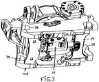
- a double-action hydraulic cylinder 33 shifts a locking plate 34 in such a manner that the working tool 5 becomes locked/fixed relative to the lower holder 16A, whereby fastening pins 7,8 at the working tools holder 16B are fixed in recesses 35-38 at the lower holder 16A.
- an electrical swivel 60 is arranged at the centre part 51 of the hydraulic swivel 50, whereby the outer part 61 of the electrical swivel 60 is fixed in a non-turning manner to the central part 51 by screws 65 that engage threaded holes 66 in the centre part 51.
- the middle part 62 of the electrical swivel 60 is rotatable relative to the outer part 61.
- the centre part 51 comprises a through axial hole 55 of such a size that a section 63 of the outer part 61 of the electrical swivel 60 can be housed in this hole 55.
- Electrical lines 70 or signal lines running to the outer part 61 of the electrical swivel 60 extend from an original source and via the hole 55 to the connection to the outer part 61 of the electrical swivel 60.
- Electrical lines 71 or signal lines running from the middle part 62 of the electrical swivel 60 have an electrical communication/signal communication maintained with lines 70, whereby the presence of the electrical swivel eliminates the turning (twisting) of the electrical lines/signal lines 70,71 when the rotation device 20 exerts a rotational movement in order to turn or rotate the working tool 5.
- a combined rotation and tilting also does not cause any problems as concerns the function of the electrical swivel.
- the electrical swivel participates in the tilting movement.
- the electrical swivel 60 can also be placed, if desired, at an upper end of the hydraulic swivel 50. A certain eccentric placing is also possible.
- sensors are arranged at the lower holder 16A in order to verify a correct rigid coupling of a working tool 5.
- the sensors communicate via lines 70,71 with, for example, a display in an operator's cabin so that an operator obtains continuous information about whether the working tool is correctly rigidly set.
- An alarm can be arranged in order to further increase safety.
- the electrical swivel 60 also makes it possible that corresponding sensor equipment can be arranged on the parts following the rotation, for example, for verifications and controls, etc.
- the electrical swivel 60 also makes it possible to equip the working tool 5 itself with sensors in order to transmit relevant information via lines 70,71 to the vehicle operator.
- the required connectors for setting up the required line communication can simply be arranged on the holder 16A and 16B so that an automatic line coupling takes place upon the rigid coupling of the working tool 5.
- the invention also makes possible the placing of illumination devices on the lower holder 16A or directly on the working tools so that the illumination always follows the movement patterns of the working tool, which brings about an excellent working illumination for the operator.
- the electrical swivel 60 also makes possible the use of, for example, electrical valves, electrically controlled hydraulic valves and electrical adjusting tools on rotating and tilting parts, which makes possible, for example, an electrical locking of the working tool.
- Fig. 5 shows an alternative rotation device 220 that comprises a rotator 110 whose construction concept is built on a so-called hydraulically driven wing motor.
- the rotator 110 comprises a stator part 120 that is normally connected to a working arm and comprises a rotor part 130 that is normally connected to a working tool.
- the stator part 120 comprises a projecting swivel part 160 that cooperates with a recess 151 in the rotor shaft 131 so that a swivel device 150 for transmitting media is obtained.
- the working tool obtains its hydraulic oil supply via groove 161 and conduits 154 in swivel device 150.
- an electrical swivel 260 is arranged at the lower end of the swivel part 160 in an area inside the hydraulic motor/the rotation device/the rotator 110.
- Lines connected to the electrical swivel 260 are designated by 170 and 171.
- the placing of the electrical swivel 260 can vary based on the formation of the constructive details.
- the rotation device 220 shown in fig. 5 is suitable, among other things, for being used with working arms in forest machines and woodworking machines where the working tool is flexibly suspended and where a tilting device is normally not integrated.
- rotation devices 20 and 220 only constitute examples of suitable embodiments that comprise electrical swivels 60,260 and it can therefore be seen that the invention can be varied in many different ways above and beyond that which was described above.
- the tilting device can be included or excluded depending on the desired goal as concerns the capacity for movement of the manoeuvring device.
Landscapes
- Engineering & Computer Science (AREA)
- Mechanical Engineering (AREA)
- Mining & Mineral Resources (AREA)
- Civil Engineering (AREA)
- General Engineering & Computer Science (AREA)
- Structural Engineering (AREA)
- Operation Control Of Excavators (AREA)
- Machine Tool Units (AREA)
Priority Applications (1)
| Application Number | Priority Date | Filing Date | Title |
|---|---|---|---|
| PL11841613T PL2640658T3 (pl) | 2010-11-15 | 2011-11-15 | Urządzenie powiązane z ramieniem roboczym |
Applications Claiming Priority (3)
| Application Number | Priority Date | Filing Date | Title |
|---|---|---|---|
| SE1001111A SE1001111A1 (sv) | 2010-11-15 | 2010-11-15 | Förfarande och anordning vid en arbetsarm |
| SE1100099A SE1100099A1 (sv) | 2010-11-15 | 2011-02-14 | Förfarande och anordning vid en arbetsarm |
| PCT/SE2011/000205 WO2012067559A1 (en) | 2010-11-15 | 2011-11-15 | Method and device related to a working arm |
Publications (3)
| Publication Number | Publication Date |
|---|---|
| EP2640658A1 EP2640658A1 (en) | 2013-09-25 |
| EP2640658A4 EP2640658A4 (en) | 2018-02-28 |
| EP2640658B1 true EP2640658B1 (en) | 2020-01-15 |
Family
ID=46084277
Family Applications (1)
| Application Number | Title | Priority Date | Filing Date |
|---|---|---|---|
| EP11841613.0A Active EP2640658B1 (en) | 2010-11-15 | 2011-11-15 | Device related to a working arm |
Country Status (4)
| Country | Link |
|---|---|
| EP (1) | EP2640658B1 (sv) |
| PL (1) | PL2640658T3 (sv) |
| SE (1) | SE1100099A1 (sv) |
| WO (1) | WO2012067559A1 (sv) |
Families Citing this family (6)
| Publication number | Priority date | Publication date | Assignee | Title |
|---|---|---|---|---|
| EP2669439B1 (en) * | 2012-05-29 | 2014-12-24 | Giorgio Bini | Rotary joint for an electrohydraulic transmission |
| CA2886209C (en) * | 2012-10-08 | 2022-05-03 | Rototilt Group Ab | Apparatus for connecting an appliance/tool and a method therefor |
| SE538587C2 (sv) | 2013-10-04 | 2016-09-27 | Binar Quick-Lift Systems Ab | Svivel |
| FI127285B (sv) | 2016-05-25 | 2018-03-15 | Ponsse Oyj | Konstruktion för en rotationsanordning samt motsvarande rotationsanordning och skogsmaskin |
| SE541642C2 (en) * | 2016-08-26 | 2019-11-19 | Indexator Rotator Sys Ab | Rotator arrangement with hydraulic coupling through rotor |
| KR101793961B1 (ko) | 2017-05-08 | 2017-11-06 | (주) 벽강산기 | 로테이팅 암 제어시스템을 가지는 굴삭기 |
Citations (10)
| Publication number | Priority date | Publication date | Assignee | Title |
|---|---|---|---|---|
| US5727442A (en) | 1994-03-02 | 1998-03-17 | Wimmer Hartstahl Ges.Mbh & Co. Kg | Safety device at hydraulic piston-cylinder units |
| US5908060A (en) | 1998-01-28 | 1999-06-01 | Prenbec Inc. | Tree processing machine |
| WO1999037136A1 (en) | 1998-01-20 | 1999-07-29 | Rotobec Inc. | Continuous rotary link for multifunction head |
| WO2004072387A1 (en) | 2003-02-17 | 2004-08-26 | Oilquick Ab | A system comprising an implement attachment means and an implement |
| US7311489B2 (en) | 2001-11-26 | 2007-12-25 | Komatsu Forest Ab | Device for mounting of a turnable implement |
| WO2009035392A1 (en) | 2007-09-12 | 2009-03-19 | Bruno Vedin | Apparatus for driving down or pulling up elongated objects |
| WO2009085825A1 (en) | 2007-12-21 | 2009-07-09 | Caterpillar Trimble Control Technologies Llc | Control system for the tool coupling of an excavator |
| WO2010047637A1 (en) | 2008-10-21 | 2010-04-29 | Svab Hydraulik Ab | A control system for controlling a tiltrotator, a method for calibrating a control system of a tiltrotator and a method for leveling a tool attached to a tiltrotator |
| GB2464988A (en) | 2008-11-03 | 2010-05-05 | Miller Int Ltd | Coupler with coupling status sensors |
| US7735530B1 (en) | 2006-10-20 | 2010-06-15 | Puma, Llc | Rotary dangle head having continuous rotation |
Family Cites Families (1)
| Publication number | Priority date | Publication date | Assignee | Title |
|---|---|---|---|---|
| SE524754C2 (sv) * | 2002-01-21 | 2004-09-28 | Indexator Ab | Rotator med vridlägesgivare samt förfarande för vridlägesbestämning vid en rotator |
-
2011
- 2011-02-14 SE SE1100099A patent/SE1100099A1/sv not_active Application Discontinuation
- 2011-11-15 EP EP11841613.0A patent/EP2640658B1/en active Active
- 2011-11-15 PL PL11841613T patent/PL2640658T3/pl unknown
- 2011-11-15 WO PCT/SE2011/000205 patent/WO2012067559A1/en active Application Filing
Patent Citations (10)
| Publication number | Priority date | Publication date | Assignee | Title |
|---|---|---|---|---|
| US5727442A (en) | 1994-03-02 | 1998-03-17 | Wimmer Hartstahl Ges.Mbh & Co. Kg | Safety device at hydraulic piston-cylinder units |
| WO1999037136A1 (en) | 1998-01-20 | 1999-07-29 | Rotobec Inc. | Continuous rotary link for multifunction head |
| US5908060A (en) | 1998-01-28 | 1999-06-01 | Prenbec Inc. | Tree processing machine |
| US7311489B2 (en) | 2001-11-26 | 2007-12-25 | Komatsu Forest Ab | Device for mounting of a turnable implement |
| WO2004072387A1 (en) | 2003-02-17 | 2004-08-26 | Oilquick Ab | A system comprising an implement attachment means and an implement |
| US7735530B1 (en) | 2006-10-20 | 2010-06-15 | Puma, Llc | Rotary dangle head having continuous rotation |
| WO2009035392A1 (en) | 2007-09-12 | 2009-03-19 | Bruno Vedin | Apparatus for driving down or pulling up elongated objects |
| WO2009085825A1 (en) | 2007-12-21 | 2009-07-09 | Caterpillar Trimble Control Technologies Llc | Control system for the tool coupling of an excavator |
| WO2010047637A1 (en) | 2008-10-21 | 2010-04-29 | Svab Hydraulik Ab | A control system for controlling a tiltrotator, a method for calibrating a control system of a tiltrotator and a method for leveling a tool attached to a tiltrotator |
| GB2464988A (en) | 2008-11-03 | 2010-05-05 | Miller Int Ltd | Coupler with coupling status sensors |
Non-Patent Citations (1)
| Title |
|---|
| ANONYMOUS: "Tiltrotators", ROTOTILT INC, Retrieved from the Internet <URL:https://www.rototilt.com/en-us/products/tiltrotators/> |
Also Published As
| Publication number | Publication date |
|---|---|
| PL2640658T3 (pl) | 2020-05-18 |
| SE1100099A1 (sv) | 2012-05-16 |
| EP2640658A4 (en) | 2018-02-28 |
| EP2640658A1 (en) | 2013-09-25 |
| WO2012067559A1 (en) | 2012-05-24 |
Similar Documents
| Publication | Publication Date | Title |
|---|---|---|
| EP2640658B1 (en) | Device related to a working arm | |
| CN101970792B (zh) | 用于钻杆的抓钩装置 | |
| CA3038050A1 (en) | Rock cutting device | |
| KR101872816B1 (ko) | 굴삭기용 로테이터 | |
| CN205100262U (zh) | 用于机器的液压驱动的作业工具组件 | |
| US11365526B2 (en) | Structure of a rotation device, and a corresponding rotation device, and a forest machine | |
| US8721248B2 (en) | Rotator | |
| AU2010200202A1 (en) | Fixing arrangement for a work piece | |
| KR20030050190A (ko) | 중장비 조종박스의 높낮이 조절장치 | |
| CA2658201A1 (en) | A method and a device for directional control of a rock drilling machine | |
| JP3194637B2 (ja) | 回動部におけるセンサ取付構造 | |
| KR20010090657A (ko) | 굴삭기용 회전식 클램프 | |
| CN201778655U (zh) | 车载钻修机后操作室的旋转装置 | |
| CN112502234A (zh) | 一种液压侧倾旋转装置 | |
| EP2362023A1 (en) | Hydraulic drive system for construction machine | |
| CN220666214U (zh) | 一种螺旋锚信息化施工系统 | |
| CN214033869U (zh) | 一种液压侧倾旋转装置 | |
| US11583867B2 (en) | Self-powered concrete/steel structure disassembling apparatus | |
| JP3817271B2 (ja) | 削岩装置 | |
| JP3239467U (ja) | 油圧ショベルのアーム回転装置 | |
| SE1001111A1 (sv) | Förfarande och anordning vid en arbetsarm | |
| US4327506A (en) | Gear case for a suction cutter dredger | |
| JP6783177B2 (ja) | ショベル | |
| JP4533281B2 (ja) | 作業機械 | |
| CN207108327U (zh) | 起重装备组件及具有其的工程机械 |
Legal Events
| Date | Code | Title | Description |
|---|---|---|---|
| PUAI | Public reference made under article 153(3) epc to a published international application that has entered the european phase |
Free format text: ORIGINAL CODE: 0009012 |
|
| 17P | Request for examination filed |
Effective date: 20130603 |
|
| AK | Designated contracting states |
Kind code of ref document: A1 Designated state(s): AL AT BE BG CH CY CZ DE DK EE ES FI FR GB GR HR HU IE IS IT LI LT LU LV MC MK MT NL NO PL PT RO RS SE SI SK SM TR |
|
| DAX | Request for extension of the european patent (deleted) | ||
| RAP1 | Party data changed (applicant data changed or rights of an application transferred) |
Owner name: ROTOTILT GROUP AB |
|
| RA4 | Supplementary search report drawn up and despatched (corrected) |
Effective date: 20180129 |
|
| RIC1 | Information provided on ipc code assigned before grant |
Ipc: B66C 13/14 20060101ALI20180123BHEP Ipc: E02F 3/36 20060101AFI20180123BHEP |
|
| REG | Reference to a national code |
Ref country code: DE Ref legal event code: R079 Ref document number: 602011064673 Country of ref document: DE Free format text: PREVIOUS MAIN CLASS: B66C0013140000 Ipc: E02F0003360000 |
|
| RIC1 | Information provided on ipc code assigned before grant |
Ipc: E02F 3/36 20060101AFI20190807BHEP Ipc: B66C 13/14 20060101ALI20190807BHEP |
|
| GRAP | Despatch of communication of intention to grant a patent |
Free format text: ORIGINAL CODE: EPIDOSNIGR1 |
|
| STAA | Information on the status of an ep patent application or granted ep patent |
Free format text: STATUS: GRANT OF PATENT IS INTENDED |
|
| INTG | Intention to grant announced |
Effective date: 20191017 |
|
| GRAS | Grant fee paid |
Free format text: ORIGINAL CODE: EPIDOSNIGR3 |
|
| GRAA | (expected) grant |
Free format text: ORIGINAL CODE: 0009210 |
|
| STAA | Information on the status of an ep patent application or granted ep patent |
Free format text: STATUS: THE PATENT HAS BEEN GRANTED |
|
| AK | Designated contracting states |
Kind code of ref document: B1 Designated state(s): AL AT BE BG CH CY CZ DE DK EE ES FI FR GB GR HR HU IE IS IT LI LT LU LV MC MK MT NL NO PL PT RO RS SE SI SK SM TR |
|
| REG | Reference to a national code |
Ref country code: CH Ref legal event code: EP Ref country code: GB Ref legal event code: FG4D |
|
| REG | Reference to a national code |
Ref country code: IE Ref legal event code: FG4D |
|
| REG | Reference to a national code |
Ref country code: DE Ref legal event code: R096 Ref document number: 602011064673 Country of ref document: DE |
|
| REG | Reference to a national code |
Ref country code: AT Ref legal event code: REF Ref document number: 1225258 Country of ref document: AT Kind code of ref document: T Effective date: 20200215 |
|
| REG | Reference to a national code |
Ref country code: FI Ref legal event code: FGE |
|
| REG | Reference to a national code |
Ref country code: SE Ref legal event code: TRGR |
|
| REG | Reference to a national code |
Ref country code: NL Ref legal event code: FP |
|
| REG | Reference to a national code |
Ref country code: NO Ref legal event code: T2 Effective date: 20200115 |
|
| REG | Reference to a national code |
Ref country code: LT Ref legal event code: MG4D |
|
| PG25 | Lapsed in a contracting state [announced via postgrant information from national office to epo] |
Ref country code: PT Free format text: LAPSE BECAUSE OF FAILURE TO SUBMIT A TRANSLATION OF THE DESCRIPTION OR TO PAY THE FEE WITHIN THE PRESCRIBED TIME-LIMIT Effective date: 20200607 Ref country code: RS Free format text: LAPSE BECAUSE OF FAILURE TO SUBMIT A TRANSLATION OF THE DESCRIPTION OR TO PAY THE FEE WITHIN THE PRESCRIBED TIME-LIMIT Effective date: 20200115 |
|
| REG | Reference to a national code |
Ref country code: AT Ref legal event code: UEP Ref document number: 1225258 Country of ref document: AT Kind code of ref document: T Effective date: 20200115 |
|
| PG25 | Lapsed in a contracting state [announced via postgrant information from national office to epo] |
Ref country code: LV Free format text: LAPSE BECAUSE OF FAILURE TO SUBMIT A TRANSLATION OF THE DESCRIPTION OR TO PAY THE FEE WITHIN THE PRESCRIBED TIME-LIMIT Effective date: 20200115 Ref country code: HR Free format text: LAPSE BECAUSE OF FAILURE TO SUBMIT A TRANSLATION OF THE DESCRIPTION OR TO PAY THE FEE WITHIN THE PRESCRIBED TIME-LIMIT Effective date: 20200115 Ref country code: GR Free format text: LAPSE BECAUSE OF FAILURE TO SUBMIT A TRANSLATION OF THE DESCRIPTION OR TO PAY THE FEE WITHIN THE PRESCRIBED TIME-LIMIT Effective date: 20200416 Ref country code: IS Free format text: LAPSE BECAUSE OF FAILURE TO SUBMIT A TRANSLATION OF THE DESCRIPTION OR TO PAY THE FEE WITHIN THE PRESCRIBED TIME-LIMIT Effective date: 20200515 Ref country code: BG Free format text: LAPSE BECAUSE OF FAILURE TO SUBMIT A TRANSLATION OF THE DESCRIPTION OR TO PAY THE FEE WITHIN THE PRESCRIBED TIME-LIMIT Effective date: 20200415 |
|
| REG | Reference to a national code |
Ref country code: DE Ref legal event code: R026 Ref document number: 602011064673 Country of ref document: DE |
|
| PLBI | Opposition filed |
Free format text: ORIGINAL CODE: 0009260 |
|
| PLAX | Notice of opposition and request to file observation + time limit sent |
Free format text: ORIGINAL CODE: EPIDOSNOBS2 |
|
| PG25 | Lapsed in a contracting state [announced via postgrant information from national office to epo] |
Ref country code: SM Free format text: LAPSE BECAUSE OF FAILURE TO SUBMIT A TRANSLATION OF THE DESCRIPTION OR TO PAY THE FEE WITHIN THE PRESCRIBED TIME-LIMIT Effective date: 20200115 Ref country code: EE Free format text: LAPSE BECAUSE OF FAILURE TO SUBMIT A TRANSLATION OF THE DESCRIPTION OR TO PAY THE FEE WITHIN THE PRESCRIBED TIME-LIMIT Effective date: 20200115 Ref country code: LT Free format text: LAPSE BECAUSE OF FAILURE TO SUBMIT A TRANSLATION OF THE DESCRIPTION OR TO PAY THE FEE WITHIN THE PRESCRIBED TIME-LIMIT Effective date: 20200115 Ref country code: DK Free format text: LAPSE BECAUSE OF FAILURE TO SUBMIT A TRANSLATION OF THE DESCRIPTION OR TO PAY THE FEE WITHIN THE PRESCRIBED TIME-LIMIT Effective date: 20200115 Ref country code: CZ Free format text: LAPSE BECAUSE OF FAILURE TO SUBMIT A TRANSLATION OF THE DESCRIPTION OR TO PAY THE FEE WITHIN THE PRESCRIBED TIME-LIMIT Effective date: 20200115 Ref country code: RO Free format text: LAPSE BECAUSE OF FAILURE TO SUBMIT A TRANSLATION OF THE DESCRIPTION OR TO PAY THE FEE WITHIN THE PRESCRIBED TIME-LIMIT Effective date: 20200115 Ref country code: ES Free format text: LAPSE BECAUSE OF FAILURE TO SUBMIT A TRANSLATION OF THE DESCRIPTION OR TO PAY THE FEE WITHIN THE PRESCRIBED TIME-LIMIT Effective date: 20200115 Ref country code: SK Free format text: LAPSE BECAUSE OF FAILURE TO SUBMIT A TRANSLATION OF THE DESCRIPTION OR TO PAY THE FEE WITHIN THE PRESCRIBED TIME-LIMIT Effective date: 20200115 |
|
| 26 | Opposition filed |
Opponent name: ENGCON HOLDING AB Effective date: 20201015 |
|
| REG | Reference to a national code |
Ref country code: FI Ref legal event code: MDE Opponent name: ENGCON HOLDING AB |
|
| PLBB | Reply of patent proprietor to notice(s) of opposition received |
Free format text: ORIGINAL CODE: EPIDOSNOBS3 |
|
| PG25 | Lapsed in a contracting state [announced via postgrant information from national office to epo] |
Ref country code: SI Free format text: LAPSE BECAUSE OF FAILURE TO SUBMIT A TRANSLATION OF THE DESCRIPTION OR TO PAY THE FEE WITHIN THE PRESCRIBED TIME-LIMIT Effective date: 20200115 |
|
| PG25 | Lapsed in a contracting state [announced via postgrant information from national office to epo] |
Ref country code: MC Free format text: LAPSE BECAUSE OF FAILURE TO SUBMIT A TRANSLATION OF THE DESCRIPTION OR TO PAY THE FEE WITHIN THE PRESCRIBED TIME-LIMIT Effective date: 20200115 |
|
| PG25 | Lapsed in a contracting state [announced via postgrant information from national office to epo] |
Ref country code: LU Free format text: LAPSE BECAUSE OF NON-PAYMENT OF DUE FEES Effective date: 20201115 |
|
| REG | Reference to a national code |
Ref country code: BE Ref legal event code: MM Effective date: 20201130 |
|
| PG25 | Lapsed in a contracting state [announced via postgrant information from national office to epo] |
Ref country code: IE Free format text: LAPSE BECAUSE OF NON-PAYMENT OF DUE FEES Effective date: 20201115 |
|
| APAH | Appeal reference modified |
Free format text: ORIGINAL CODE: EPIDOSCREFNO |
|
| APBM | Appeal reference recorded |
Free format text: ORIGINAL CODE: EPIDOSNREFNO |
|
| APBP | Date of receipt of notice of appeal recorded |
Free format text: ORIGINAL CODE: EPIDOSNNOA2O |
|
| PLCK | Communication despatched that opposition was rejected |
Free format text: ORIGINAL CODE: EPIDOSNREJ1 |
|
| PG25 | Lapsed in a contracting state [announced via postgrant information from national office to epo] |
Ref country code: TR Free format text: LAPSE BECAUSE OF FAILURE TO SUBMIT A TRANSLATION OF THE DESCRIPTION OR TO PAY THE FEE WITHIN THE PRESCRIBED TIME-LIMIT Effective date: 20200115 Ref country code: MT Free format text: LAPSE BECAUSE OF FAILURE TO SUBMIT A TRANSLATION OF THE DESCRIPTION OR TO PAY THE FEE WITHIN THE PRESCRIBED TIME-LIMIT Effective date: 20200115 Ref country code: CY Free format text: LAPSE BECAUSE OF FAILURE TO SUBMIT A TRANSLATION OF THE DESCRIPTION OR TO PAY THE FEE WITHIN THE PRESCRIBED TIME-LIMIT Effective date: 20200115 |
|
| PG25 | Lapsed in a contracting state [announced via postgrant information from national office to epo] |
Ref country code: MK Free format text: LAPSE BECAUSE OF FAILURE TO SUBMIT A TRANSLATION OF THE DESCRIPTION OR TO PAY THE FEE WITHIN THE PRESCRIBED TIME-LIMIT Effective date: 20200115 Ref country code: AL Free format text: LAPSE BECAUSE OF FAILURE TO SUBMIT A TRANSLATION OF THE DESCRIPTION OR TO PAY THE FEE WITHIN THE PRESCRIBED TIME-LIMIT Effective date: 20200115 |
|
| PG25 | Lapsed in a contracting state [announced via postgrant information from national office to epo] |
Ref country code: BE Free format text: LAPSE BECAUSE OF NON-PAYMENT OF DUE FEES Effective date: 20201130 |
|
| APAH | Appeal reference modified |
Free format text: ORIGINAL CODE: EPIDOSCREFNO |
|
| PGFP | Annual fee paid to national office [announced via postgrant information from national office to epo] |
Ref country code: NL Payment date: 20231120 Year of fee payment: 13 |
|
| PGFP | Annual fee paid to national office [announced via postgrant information from national office to epo] |
Ref country code: GB Payment date: 20231120 Year of fee payment: 13 |
|
| PGFP | Annual fee paid to national office [announced via postgrant information from national office to epo] |
Ref country code: SE Payment date: 20231121 Year of fee payment: 13 Ref country code: NO Payment date: 20231121 Year of fee payment: 13 Ref country code: IT Payment date: 20231120 Year of fee payment: 13 Ref country code: FR Payment date: 20231115 Year of fee payment: 13 Ref country code: FI Payment date: 20231120 Year of fee payment: 13 Ref country code: DE Payment date: 20231121 Year of fee payment: 13 Ref country code: CH Payment date: 20231201 Year of fee payment: 13 Ref country code: AT Payment date: 20231121 Year of fee payment: 13 |
|
| PGFP | Annual fee paid to national office [announced via postgrant information from national office to epo] |
Ref country code: PL Payment date: 20231017 Year of fee payment: 13 |