EP2639893B1 - Nockenbetätigtes unabhängiges Sekundärschloss - Google Patents
Nockenbetätigtes unabhängiges Sekundärschloss Download PDFInfo
- Publication number
- EP2639893B1 EP2639893B1 EP13159139.8A EP13159139A EP2639893B1 EP 2639893 B1 EP2639893 B1 EP 2639893B1 EP 13159139 A EP13159139 A EP 13159139A EP 2639893 B1 EP2639893 B1 EP 2639893B1
- Authority
- EP
- European Patent Office
- Prior art keywords
- lock
- terminals
- terminal cavities
- projections
- connector assembly
- Prior art date
- Legal status (The legal status is an assumption and is not a legal conclusion. Google has not performed a legal analysis and makes no representation as to the accuracy of the status listed.)
- Not-in-force
Links
Images


Classifications
-
- H—ELECTRICITY
- H01—ELECTRIC ELEMENTS
- H01R—ELECTRICALLY-CONDUCTIVE CONNECTIONS; STRUCTURAL ASSOCIATIONS OF A PLURALITY OF MUTUALLY-INSULATED ELECTRICAL CONNECTING ELEMENTS; COUPLING DEVICES; CURRENT COLLECTORS
- H01R13/00—Details of coupling devices of the kinds covered by groups H01R12/70 or H01R24/00 - H01R33/00
- H01R13/40—Securing contact members in or to a base or case; Insulating of contact members
- H01R13/42—Securing in a demountable manner
- H01R13/436—Securing a plurality of contact members by one locking piece or operation
- H01R13/4361—Insertion of locking piece perpendicular to direction of contact insertion
- H01R13/4362—Insertion of locking piece perpendicular to direction of contact insertion comprising a temporary and a final locking position
-
- H—ELECTRICITY
- H01—ELECTRIC ELEMENTS
- H01R—ELECTRICALLY-CONDUCTIVE CONNECTIONS; STRUCTURAL ASSOCIATIONS OF A PLURALITY OF MUTUALLY-INSULATED ELECTRICAL CONNECTING ELEMENTS; COUPLING DEVICES; CURRENT COLLECTORS
- H01R13/00—Details of coupling devices of the kinds covered by groups H01R12/70 or H01R24/00 - H01R33/00
- H01R13/40—Securing contact members in or to a base or case; Insulating of contact members
- H01R13/42—Securing in a demountable manner
- H01R13/436—Securing a plurality of contact members by one locking piece or operation
- H01R13/4364—Insertion of locking piece from the front
- H01R13/4365—Insertion of locking piece from the front comprising a temporary and a final locking position
Definitions
- the present disclosure relates to electrical connectors, and more particularly, to cam-actuated independent secondary locks.
- Conventional connectors include a connector body, lock projections, and either a primary lock reinforcement (PLR) or an independent secondary lock (ISL).
- the lock projections engage a rearward edge of terminals to retain the terminals in terminal cavities.
- the PLR and the ISL are adjusted to pre-set positions until the terminals are inserted into the terminal cavities, at which point the PLR and the ISL are independently moved to full-set positions.
- the PLR engages the lock projections to prevent the lock projections from deflecting away from terminal cavities.
- the ISL engages a rearward edge of the terminals to retain the terminals in the terminal cavities independent from the lock projections.
- a single connector may include both a PLR and an ISL.
- the PLR and the ISL must be independently moved when the connector is assembled or serviced, increasing the cost and complexity of the connector relative to conventional connectors.
- U.S. Patent No. 5,085,599 discloses a connector in which a flexible retaining piece for engagement with a terminal is disposed in a terminal receiving chamber of a housing body and a spacer for preventing the flexing of the flexible retaining piece is inserted into a gap.
- An abutment wall is provided in the housing body in opposed relation to a side surface of the flexible retaining piece.
- U.S. Patent Application Publication No. 2009/0186523 discloses an electrical connector having a housing, at least one electrical contact receiving area, which is configured to receive an electrical terminal, and a terminal position assurance member that is located on a front section of the housing.
- the terminal position assurance member is laterally movable on the front section between a locked position and an unlocked position and is configured to prevent unintentional withdrawal of the electrical contact from the electrical contact receiving area.
- a connector assembly includes a connector body, a lock reinforcement, and a secondary lock.
- the connector body has a plurality of terminal cavities and a plurality of lock projections configured to engage a plurality of terminals to retain the terminals in the terminal cavities.
- the lock reinforcement is slidable relative to the connector body for engagement with a subset of the lock projections to maintain the lock projections engaged with a first subset of the terminals.
- the secondary lock is slidable relative to the connector body for engagement with a second subset of the terminals to retain the terminals in the terminal cavities independent from the lock projections.
- the secondary lock is coupled to the lock reinforcement such that moving one of the lock reinforcement and the secondary lock moves the other one of the lock reinforcement and the secondary lock.
- the lock reinforcement includes a cam and the secondary lock includes a cam follower.
- the cam engages the cam follower to move the secondary lock into engagement with the subset of the terminals when the lock reinforcement is moved from a pre-set position to a full-set position.
- the connector body defines a first slot and a second slot.
- the first slot extends longitudinally through the connector body and receives the lock reinforcement.
- the second slot extends laterally through the connector body and receives the secondary lock.
- Example 1 A connector assembly comprising: a connector body having a plurality of terminal cavities and a plurality of lock projections that are configured to engage a first edge of the plurality of terminals to retain the plurality of terminals in the plurality of terminal cavities; a lock reinforcement that is slidably engaged with the connector body, the lock reinforcement being movable to engage a subset of the lock projections to prevent the lock projections from deflecting away from a first subset of the terminal cavities; a secondary lock that is slidably engaged with the connector body, the secondary lock being movable to engage a second edge of a subset of the terminals to retain the terminals in a second subset of the terminal cavities; and wherein the lock reinforcement engages the secondary lock, and wherein movement of one of the lock reinforcement and the secondary lock from a first position, which is associated with the connector assembly being in a pre-set condition, to a second position moves the other one of the lock reinforcement and the secondary lock such that the connector assembly is in a full-set condition.
- Example 2 The connector assembly of Example 1 wherein the connector housing defines a first slot and a second slot, the first slot extending longitudinally through the connector body and receiving the lock reinforcement, the second slot extending laterally through the connector body and receiving the secondary lock.
- Example 3 The connector assembly of Example 1 wherein the lock reinforcement includes a cam and the secondary lock includes a cam follower, the cam engaging the cam follower to move the secondary lock from a third position to a fourth position when the lock reinforcement is moved from the first position to the second position.
- Example 4 The connector assembly of Example 1 wherein the first subset of the terminal cavities and the second subset of the terminal cavities are proper subsets of the plurality of terminal cavities, and wherein the terminal cavities included in the second subset are different from the terminal cavities included in the first subset.
- Example 5 A connector assembly comprising: a connector body having a plurality of terminal cavities and a plurality of lock projections that are configured to engage a plurality of terminals to retain the plurality of terminals in the plurality of terminal cavities; a lock reinforcement that is slidable relative to the connector body for movement between a pre-set position and a full-set position, the lock reinforcement being configured to engage a subset of the lock projections to maintain the lock projections in engagement with a first subset of the terminals when the lock reinforcement is in the full-set position; and a secondary lock that is slidable relative to the connector body and is coupled to the lock reinforcement, the secondary lock being configured to engage a second subset of the terminals to retain the plurality of terminals in the plurality of terminal cavities independent from the plurality of lock projections when the lock reinforcement is in the full-set position.
- Example 6 The connector assembly of Example 5 wherein the connector body defines a first slot and a second slot, the first slot extending longitudinally through the connector body and receiving the lock reinforcement, the second slot extending laterally through the connector body and receiving the secondary lock.
- Example 7 The connector assembly of Example 5 wherein the lock reinforcement includes a cam and the secondary lock includes a cam follower, the cam engaging the cam follower to move the secondary lock into engagement with the second subset of the terminals when the lock reinforcement is moved from the pre-set position to the full-set position.
- Example 8 The connector assembly of Example 5 wherein the first subset of the terminal cavities and the second subset of the terminal cavities are proper subsets of the plurality of terminal cavities, and wherein the terminal cavities included in the second subset are different from the terminal cavities included in the first subset.
- first, second, third, etc. may be used herein to describe various elements, components, regions, layers and/or sections, these elements, components, regions, layers and/or sections should not be limited by these terms. These terms may be only used to distinguish one element, component, region, layer or section from another region, layer or section. Terms such as “first,” “second,” and other numerical terms when used herein do not imply a sequence or order unless clearly indicated by the context. Thus, a first element, component, region, layer or section discussed below could be termed a second element, component, region, layer or section without departing from the teachings of the example embodiments.
- spatially relative terms such as “inner,” “outer,” “beneath,” “below,” “lower,” “above,” “upper,” and the like, may be used herein for ease of description to describe one element or feature's relationship to another element(s) or feature(s) as illustrated in the figures.
- Spatially relative terms may be intended to encompass different orientations of the device in use or operation in addition to the orientation depicted in the figures. For example, if the device in the figures is turned over, elements described as “below” or “beneath” other elements or features would then be oriented “above” the other elements or features.
- the example term “below” can encompass both an orientation of above and below.
- the device may be otherwise oriented (rotated 90 degrees or at other orientations) and the spatially relative descriptors used herein interpreted accordingly.
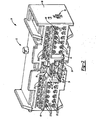
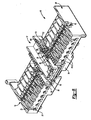
- the connector assembly 10 can comprise a connector body 12, a primary lock reinforcement (PLR) 14, and a pair of independent secondary locks (ISLs) 16.
- the connector body 12, the PLR 14, and the ISLs 16 can be separately formed, such as by injection molding, from plastic.
- the connector body 12 can have a generally rectangular prismatic shape.
- the connector body 12 can define a first plurality of terminal cavities 18, a second plurality of terminal cavities 20, a third plurality of terminal cavities 22, a first slot 24, and a pair of second slots 26 (only one shown).
- the terminal cavities 18 can be larger than the terminal cavities 20, and the terminal cavities 20 can be larger than the terminal cavities 22.
- the connector body 12 can include a first terminal housing 28, a second terminal housing 30, and a pair of guide rails 32.
- the first terminal housing 28 encloses the lower one of the terminal cavities 18, and the second terminal housing 30 encloses the upper one of the terminal cavities 18.
- the guide rails 32 extend longitudinally beneath the terminal cavities 20.
- the first slot 24 can be configured to receive the PLR 14, and the second slots 26 can be configured to receive the ISLs 16.
- the first slot 24 can extend longitudinally through a front face 34 of the connector body 12, beneath the terminal cavities 18, 20 and between the terminal cavities 18.
- the second slots 26 can extend laterally through opposite sides 36 (only one shown) of the connector body 12 and between the terminal cavities 22.
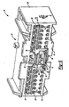
- the PLR 14 can include a generally rectangular body 38 and a pair of support members 40 that extend laterally outward from the rectangular body 38.
- the rectangular body 38 can include a base 42, a pair of walls 44 extending upward from the base 42, and a bridge 46 extending between and connecting the walls 44.
- the rectangular body 38 can define a passage 48 that extends longitudinally through the rectangular body 38.
- the passage 48 can be configured to receive the first terminal housing 28.
- the walls 44 can define a pair of tracks 50 that extend longitudinally through the walls 44 and a pair of slots 52 that extend laterally through the walls 44.
- a top surface 54 of the rectangular body 38 can be indented to accommodate the second terminal housing 30.
- Each of the support members 40 can define longitudinally-extending guide slots 56.
- the guide slots 56 can be configured to receive the guide rails 32 on the connector body 12 as the PLR 14 is inserted into the first slot 24 in the connector body 12.
- Each of the support members 40 can include a rectangular body 58 and a plurality of projections 60 that extend upward from the rectangular body 58.
- Each of the projections 60 can include a retention feature 62 and a guide rail 64 that extends longitudinally from the retention feature 62.
- Each of the ISLs 16 can have a generally elongated shape and include a rectangular body 68, a pair of bosses 70, alternating projections 72, 74, and a pair of tabs 76.
- the bosses 70, the projections 72, 74, and the tabs 76 can extend vertically from opposite sides 78 of the rectangular body 68.
- the projections 72 may have a first height and the projections 74 may have a second height that is greater than the first height.
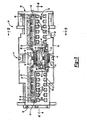
- the connector assembly 10 is shown in a pre-set condition associated with the PLR 14 and the ISLs 16 being in pre-set positions.
- the PLR 14 and the ISLs 16 may be adjusted to their respective pre-set positions when the connector assembly 10 is first assembled.
- the ISLs 16 may be inserted into the connector body 12 before the PLR 14 is inserted into the connector body 12 to avoid interference between the ISLs 16 and the walls 44 of the PLR 14.
- the PLR 14 and the ISLs 16 may be returned to their respective pre-set positions when the connector assembly 10 is disassembled.
- the connector body 12 and the PLR 14 can cooperate to form a first pair of detents 80 that are configured to maintain the PLR 14 in its pre-set position.
- Each of the detents 80 can include a ramped projection 82 and a tab 84.
- the ramped projections 82 extend vertically from a surface 86 of the connector body 12, and the tabs 84 extend laterally along the rear end of the PLR 14.
- the tabs 84 can be slid over the ramped projections 82.
- the ramped projections 82 can then engage the tabs 84 to maintain the PLR 14 in its pre-set position.
- Each of the tracks 50 extending through the PLR 14 can include a first portion 88, a second portion 90, and a third portion 92.
- the first portions 88 can engage the bosses 70 on the ISLs 16 when the PLR 14 and the ISLs 16 are in their respective pre-set positions to maintain the ISLs 16 in their pre-set positions.
- the first portions 88 and the third portions 92 can extend longitudinally through the walls 44 of the PLR 14.
- the second portions 90 can extend longitudinally and laterally between the first portions 88 and the third portions 92.
- the terminal cavities 18 shown in Figures 1 through 3 can be configured to receive a first plurality of terminals (not shown), the terminal cavities 20 can be configured to receive a second plurality of terminals 94, and the terminal cavities 22 can be configured to receive a third plurality of terminals 96.
- the first plurality of terminals can have a first blade width (e.g., 6.3 millimeters (mm))
- the second plurality of terminals 94 can have a second blade width (e.g., 2.8 mm)
- the third plurality of terminals 96 can have a third blade width.
- the first blade width can be greater than the second blade width and the second blade width can be greater than the third blade width.
- a first plurality of lock projections (not shown), a second plurality of lock projections 98, and a third plurality of lock projections 100 can extend into the terminal cavities 18, 20, 22, respectively, and can be unitarily formed with the connector body 12.
- the first plurality of lock projections and the second plurality of lock projections 98 can be arms that flex to allow insertion of the first plurality of terminals and the second plurality of terminals 94 into the terminal cavities 18, 20, respectively.
- the lock projections 98 can engage a rearward edge 102 of the terminals 94 to retain the terminals 94 in the terminal cavities 20.
- the lock projections 100 can engage a rearward edge 104 of the terminals 96 to retain the terminals 96 in the terminal cavities 22.
- the first plurality of lock projections can retain the first plurality of terminals in a similar manner.
- the support member 40 of the PLR 14 When the PLR 14 is in its pre-set position as shown in Figure 5 , the support member 40 of the PLR 14 is retracted from a gap 106 between the lock projections 98 and the connector body 12. Thus, the support member 40 does not prevent the lock projections 98 from flexing downward as the terminals 94 are inserted into or removed from the terminal cavities 20. Therefore, the terminals 94 can be inserted into or removed from the terminal cavities 20 when the PLR 14 is in its pre-set position. Similarly, the support member 40 does not prevent the first plurality of lock projections from flexing as the first plurality of terminals are inserted into or removed from the terminal cavities 18. Therefore, the first plurality of terminals can be inserted into or removed from the terminal cavities 18 when the PLR 14 is in its pre-set position.
- the projections 72 on the ISLs 16 are aligned with the terminal cavities 22.
- the first height of the projections 72 can be selected to avoid interference between the projections 72 and the terminals 96 as the terminals 96 are inserted into or removed from the terminal cavities 22 when the ISLs 16 are in their pre-set positions. Therefore, the terminals 96 can be inserted into or removed from the terminal cavities 22 when the ISLs 16 are in thier pre-set positions.
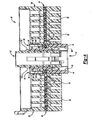
- the connector assembly 10 is shown in a full-set condition associated with the PLR 14 and the ISLs 16 being in full-set positions.
- the PLR 14 and the ISLs 16 may be adjusted to their respective full-set positions after the first plurality of terminals, the second plurality of terminals 94, and the third plurality of terminals 96 are inserted into the terminal cavities 18, 20, 22, respectively.
- the PLR 14 and the ISLs 16 are mechanically linked such that moving the PLR 14 from its pre-set position to its full-set position moves the ISLs 16 from their pre-set positions to their full-set positions.
- the mechanical link also ensure that moving the PLR 14 from its full-set position to its pre-set position moves the ISLs 16 from their full-set positions to their pre-set positions.
- the PLR 14 and the ISL 16 can be mechanically linked such that moving one or both of the ISLs 16 between their pre-set positions and their full-set positions moves the PLR 14 between its pre-set position and its full-set position.
- the tracks 50 can engage the bosses 70 to move the ISLs 16 laterally outward.
- the tracks 50 can engage the bosses 70 to move the ISLs 16 from their full-set positions to their pre-set positions.
- the PLR 14 and the ISLs 16 can cooperate to form a cam mechanism with the tracks 50 acting as a cam and the bosses 70 acting as a cam follower.
- the connector body 12 and the PLR 14 can cooperate to form a second pair of detents 108 that are configured to maintain the PLR 14 in its full-set position.
- Each of the detents 108 can include a ramped projection 110 and a tab 112.
- the ramped projections 110 extend laterally from a surface 114 of the connector body 12, and the tabs 112 extend vertically along the rear end of the PLR 14.
- the tabs 112 can be slid over the ramped projections 110.
- the ramped projections 110 can then engage the tabs 112 to maintain the PLR 14 in its full-set position.
- the third portions 92 of the tracks 50 can engage the bosses 70 on the ISLs 16 to maintain the ISLs 16 in their full-set positions.
- the support member 40 of the PLR 14 is disposed in the gap 106 between the lock projections 98 and the connector body 12.
- the support member 40 supports the lock projections 98 by preventing the lock projections 98 from flexing downward.
- the PLR 14 reinforces the lock projections 98 to retain the terminals 94 in the terminal cavities 20 when the PLR 14 is in its full-set position.
- the support member 40 supports the first plurality of lock projections by preventing the first plurality of lock projections from flexing vertically when the PLR 14 is in its full-set position. In this manner, the PLR 14 reinforces the first plurality of lock projections to retain the first plurality of terminals in the terminal cavities 18 when the PLR 14 is in its full-set position.
- the projections 74 on the ISLs 16 are aligned with the terminal cavities 22.
- the projections 74 on the ISLs 16 engage a rearward edge 116 of the terminals 96 to retain the terminals 96 in the terminal cavities 22.
- the ISLs 16 retains the terminals 96 in the terminal cavities 22 independent from the lock projections 100 on the connector body 12 when the ISLs 16 are in their full-set positions.
- the PLR 14 and the ISLs 16 cooperate to form a cam mechanism with the PLR 14 including the tracks 50 that act as a cam and the ISLs 16 including the bosses 70 that act as a cam follower.
- the PLR 14 can include a feature that acts as cam follower and the ISLs 16 can include a feature that acts as a cam.
- the PLR 14 and the ISLs 16 can be mechanically linked using other mechanisms such gears, linkages, and/or flexure mechanisms.
- the PLR 14 is mechanically linked to the pair of ISLs 16.
- the PLR 14 can be mechanically linked to a single ISL, or the PLR 14 can be mechanically linked to more than two ISLs.
Landscapes
- Details Of Connecting Devices For Male And Female Coupling (AREA)
- Connector Housings Or Holding Contact Members (AREA)
Claims (12)
- Verbinderanordnung, umfassend
ein Verbindergehäuse, das einen Verbinderkörper (12) mit einer Vielzahl von Anschlusshohlräumen (18, 20, 22), einer ersten Aussparung (24) und einer zweiten Aussparung (26) umfasst, wobei die Vielzahl von Anschlusshohlräumen (18, 20, 22) ausgestaltet ist, um eine Vielzahl von Anschlüssen (94, 96) aufzunehmen, wobei die erste Aussparung (24) sich längs durch den Verbinderkörper (12) erstreckt, wobei die zweite Aussparung (26) sich seitlich durch den Verbinderkörper (12) erstreckt, wobei der Verbinderkörper (12) eine erste Vielzahl von Verriegelungsvorsprüngen (98) umfasst, die ausgestaltet sind, um mit einer ersten Kante (102) der Vielzahl von Anschlüssen (94) einzugreifen, um die Vielzahl von Anschlüssen (94) in der Vielzahl von Anschlusshohlräumen (20) zu halten,
eine Verriegelungsverstärkung (14), die verschiebbar in der ersten Aussparung (24) zur Bewegung zwischen einer ersten Position und einer zweiten Position aufgenommen ist, wobei die Verriegelungsverstärkung (14) mit einer Untermenge der Verriegelungsvorsprünge (98) eingreift, wenn die Verriegelungsverstärkung (14) in der zweiten Position ist, um Auslenkung der Verriegelungsvorsprünge (98) weg von einer ersten Untermenge der Anschlusshohlräume (20) zu verhindern,
einen zweiten Riegel (16), der in der zweiten Aussparung (26) zur Bewegung zwischen einer dritten Position und einer vierten Position verschiebbar aufgenommen ist, wobei der zweite Riegel (16) ausgestaltet ist, um mit einer zweiten Kante einer Untermenge der Anschlüsse (96) einzugreifen, wenn der zweite Riegel (16) in der vierten Position ist,
dadurch gekennzeichnet, dass die Verriegelungsverstärkung (14) eine Nocke (50) umfasst,
dass der zweite Riegel (16) ausgestaltet ist, um mit der zweiten Kante einer Untermenge der Anschlüsse (96) einzugreifen, wenn der zweite Riegel (16) in der vierten Position ist, um die Anschlüsse (96) in einer zweiten Untermenge der Anschlusshohlräume (22) zu halten, und
dass der zweite Riegel (16) ein Nockenelement (70) umfasst, das mit der Nocke (50) im Eingriff ist,
wobei die Nocke (50) und das Nockenelement (70) zusammenwirken, wenn die Verriegelungsverstärkung (14) in der ersten Aussparung (24) von der ersten Position zu der zweiten Position bewegt ist, um den zweiten Riegel (16) in der zweiten Aussparung (26) von der dritten Position in die vierte Position zu bewegen. - Verbinderanordnung nach Anspruch 1, wobei die erste Vielzahl von Verriegelungsvorsprüngen (98) sich längs des Verbinderkörpers (12) erstreckt.
- Verbinderanordnung nach Anspruch 2, wobei die Verriegelungsverstärkung (14) ein Stützelement (40) umfasst, das die erste Untermenge der Verriegelungsvorsprünge (98) durch Ausfüllung einer Aussparung (106) zwischen den Verriegelungsvorsprüngen (98) und dem Verbinderkörper (12) stützt, wenn die Verriegelungsverstärkung (14) in der zweiten Position ist.
- Verbinderanordnung nach Anspruch 1, wobei der zweite Riegel (16) eine zweite Vielzahl von Verriegelungsvorsprüngen (74) umfasst, die in die zweite Untermenge von Anschlusshohlräumen (22) hinein ragt und die ausgestaltet ist, um mit der zweiten Kante der Untermenge der Anschlüsse (96) einzugreifen, wenn der zweite Riegel (14) in der vierten Position ist.
- Verbinderanordnung nach Anspruch 1, wobei die Nocke (50) und das Nockenelement (70) ausgestaltet sind, um eine Bewegung des zweiten Riegels (16) weg von der dritten Position zu verhindern, wenn die Verriegelungsverstärkung (14) in der ersten Position ist.
- Verbinderanordnung nach Anspruch 1, wobei die Nocke (50) einen ersten Teil (88), der mit dem Nockenelement (70) eingreift, wenn die Verriegelungsverstärkung (14) in der ersten Position ist, und einen zweiten Teil (92) umfasst, der mit dem Nockenelement (70) eingreift, wenn die Verriegelungsverstärkung (14) in der zweiten Position ist, wobei die Nocke (50) sich längs und seitlich zwischen dem ersten Teil (88) und dem zweiten Teil (92) erstreckt.
- Verbinderanordnung nach Anspruch 1 ferner umfassend eine erste Halteraste (80), die ausgestaltet ist, um die Verriegelungsverstärkung (14) in der ersten Position zu halten, und eine zweite Halteraste (108), die ausgestaltet ist, um die Verriegelungsverstärkung (14) in der zweiten Position zu halten.
- Verbinderanordnung nach Anspruch 7, wobei die erste Halteraste (80) und die zweite Halteraste (108) jeweils einen geneigten Vorsprung (82, 110) und eine Lasche (84, 112) umfassen, wobei sich die geneigten Vorsprünge (82, 110) in die erste Aussparung (24) hinein erstrecken, wobei die Laschen (84, 112) an die Verriegelungsverstärkung (14) gekoppelt und ausgestaltet sind, um über die geneigten Vorsprünge (82, 110) zu gleiten, wenn die Verriegelungsverstärkung (14) in die erste Aussparung (24) versetzt ist.
- Verbinderanordnung nach Anspruch 1, wobei die Verriegelungsverstärkung (14) und der zweite Riegel (16) ausgestaltet sind, um zu ermöglichen, dass die Vielzahl von Anschlüssen (94, 96) in die Vielzahl von Anschlusshohlräumen (18, 20, 22) eingefügt werden, wenn die Verriegelungsverstärkung (14) und der zweite Riegel (16) jeweils in der ersten Position bzw. der dritten Position sind.
- Verbinderanordnung nach Anspruch 1, wobei die erste Aussparung (24) sich angrenzend an die erste Untermenge der Anschlusshohlräume (18) erstreckt.
- Verbinderanordnung nach Anspruch 1, wobei die zweite Aussparung (26) sich durch die zweite Untermenge der Anschlusshohlräume (22) erstreckt.
- Verbinderanordnung nach Anspruch 1, wobei der zweite Riegel (16) ein Paar von zweiten Riegeln umfasst, wobei die zweiten Riegel in entgegengesetzte Seiten des Verbinderkörpers (12) eingefügt werden.
Applications Claiming Priority (1)
| Application Number | Priority Date | Filing Date | Title |
|---|---|---|---|
| US13/419,479 US8550845B1 (en) | 2012-03-14 | 2012-03-14 | Cam-actuated independent secondary lock |
Publications (2)
| Publication Number | Publication Date |
|---|---|
| EP2639893A1 EP2639893A1 (de) | 2013-09-18 |
| EP2639893B1 true EP2639893B1 (de) | 2015-08-05 |
Family
ID=47901790
Family Applications (1)
| Application Number | Title | Priority Date | Filing Date |
|---|---|---|---|
| EP13159139.8A Not-in-force EP2639893B1 (de) | 2012-03-14 | 2013-03-14 | Nockenbetätigtes unabhängiges Sekundärschloss |
Country Status (5)
| Country | Link |
|---|---|
| US (1) | US8550845B1 (de) |
| EP (1) | EP2639893B1 (de) |
| JP (1) | JP5529316B2 (de) |
| DK (1) | DK2639893T3 (de) |
| PT (1) | PT2639893E (de) |
Families Citing this family (9)
| Publication number | Priority date | Publication date | Assignee | Title |
|---|---|---|---|---|
| DE102013014753B4 (de) * | 2013-09-06 | 2021-03-18 | Lisa Dräxlmaier GmbH | Vorrichtung zum Bearbeiten von mehreren Bauelementen einer Palette mit Sekundärverriegelung, und Verfahren |
| DE102013019874B4 (de) * | 2013-11-28 | 2020-08-06 | Lisa Dräxlmaier GmbH | Stecker und Gegenstecker |
| JP6260510B2 (ja) * | 2014-10-15 | 2018-01-17 | 株式会社オートネットワーク技術研究所 | コネクタ |
| JP6332046B2 (ja) * | 2015-01-14 | 2018-05-30 | 住友電装株式会社 | コネクタ |
| JP6944931B2 (ja) * | 2016-05-18 | 2021-10-06 | 日本端子株式会社 | コネクタ |
| DE102016217456B3 (de) | 2016-09-13 | 2017-12-21 | Te Connectivity Germany Gmbh | Anordnung für einen elektrischen Steckverbinder sowie Steckverbinder mit einem Kontaktgehäuse, Umgehäuse und Sicherungselement |
| US10218124B1 (en) * | 2017-10-20 | 2019-02-26 | Lear Corporation | Electrical connector with terminal position assurance |
| US10181679B1 (en) * | 2017-10-20 | 2019-01-15 | Lear Corporation | Electrical connector with terminal position assurance |
| WO2020164737A1 (de) * | 2019-02-15 | 2020-08-20 | Hirschmann Automotive Gmbh | Steckverbinder mit verbessertem schutz gegenüber hochspannungsüberschlägen |
Family Cites Families (27)
| Publication number | Priority date | Publication date | Assignee | Title |
|---|---|---|---|---|
| JPH07114131B2 (ja) | 1990-05-16 | 1995-12-06 | 矢崎総業株式会社 | コネクタ |
| JP2789973B2 (ja) | 1992-11-06 | 1998-08-27 | 住友電装株式会社 | コネクタ |
| US5281168A (en) | 1992-11-20 | 1994-01-25 | Molex Incorporated | Electrical connector with terminal position assurance system |
| FR2726403B1 (fr) | 1994-10-28 | 1996-11-29 | Cinch Connecteurs Sa | Connecteur electrique |
| US5595509A (en) | 1995-08-14 | 1997-01-21 | Molex Incorporated | Electrical connector with terminal position assurance system |
| JP3265971B2 (ja) | 1996-03-14 | 2002-03-18 | 矢崎総業株式会社 | 二重係止コネクタ |
| US5967859A (en) * | 1997-12-10 | 1999-10-19 | Molex Incorporated | Electrical connector assembly with terminal retainer system |
| US5890935A (en) * | 1997-12-10 | 1999-04-06 | Molex Incorporated | Electrical connector with terminal position assurance device |
| US6142826A (en) | 1998-03-13 | 2000-11-07 | The Whitaker Corporation | Sealed electrical connector with secondary locking member |
| JP3983380B2 (ja) * | 1998-06-08 | 2007-09-26 | 矢崎総業株式会社 | コネクタ |
| DE10017868B4 (de) | 2000-04-11 | 2004-03-04 | Leopold Kostal Gmbh & Co. Kg | Elektrisches Steckverbindungsteil |
| JP2001351716A (ja) | 2000-06-02 | 2001-12-21 | Sumitomo Wiring Syst Ltd | コネクタ |
| JP3765386B2 (ja) * | 2000-11-01 | 2006-04-12 | 住友電装株式会社 | コネクタ |
| JP3674948B2 (ja) | 2001-04-13 | 2005-07-27 | 住友電装株式会社 | コネクタ |
| DE20111964U1 (de) | 2001-07-19 | 2002-11-28 | Robert Bosch Gmbh, 70469 Stuttgart | Sekundärverriegelung für einen Kabelbaumstecker mit unterschiedlichen Kontaktarten |
| JP3986062B2 (ja) | 2003-02-10 | 2007-10-03 | 住友電装株式会社 | コネクタ |
| EP1528636B1 (de) | 2003-10-29 | 2007-11-28 | Sumitomo Wiring Systems, Ltd. | Modularer Verbinder und Demontageverfahren eines Moduls |
| JP2006040818A (ja) | 2004-07-29 | 2006-02-09 | Sumitomo Wiring Syst Ltd | コネクタ |
| JP2006185759A (ja) | 2004-12-28 | 2006-07-13 | Sumitomo Wiring Syst Ltd | コネクタ |
| JP4682706B2 (ja) | 2005-05-31 | 2011-05-11 | オムロン株式会社 | コネクタ |
| EP1739795B1 (de) | 2005-06-30 | 2007-12-26 | Sumitomo Wiring Systems, Ltd. | Verbinder, Verbinderanordnung und Montageverfahren |
| DE102006022488B4 (de) | 2006-05-15 | 2018-07-12 | Robert Bosch Gmbh | Kontaktgehäuse für eine elektrische Steckverbindung |
| US7278890B1 (en) | 2006-07-26 | 2007-10-09 | Delphi Technologies, Inc. | Electrical connector with secondary lock |
| JP4963287B2 (ja) | 2007-11-16 | 2012-06-27 | 矢崎総業株式会社 | コネクタ |
| US7914327B2 (en) | 2008-01-23 | 2011-03-29 | Fci Americas Technology, Inc. | Electrical connector |
| JP5217458B2 (ja) | 2008-01-29 | 2013-06-19 | 住友電装株式会社 | コネクタ |
| JP5508927B2 (ja) * | 2010-04-22 | 2014-06-04 | 日本航空電子工業株式会社 | コネクタ及び防水コネクタ |
-
2012
- 2012-03-14 US US13/419,479 patent/US8550845B1/en active Active
-
2013
- 2013-03-13 JP JP2013050341A patent/JP5529316B2/ja active Active
- 2013-03-14 PT PT131591398T patent/PT2639893E/pt unknown
- 2013-03-14 DK DK13159139.8T patent/DK2639893T3/en active
- 2013-03-14 EP EP13159139.8A patent/EP2639893B1/de not_active Not-in-force
Also Published As
| Publication number | Publication date |
|---|---|
| DK2639893T3 (en) | 2015-09-14 |
| PT2639893E (pt) | 2015-10-12 |
| EP2639893A1 (de) | 2013-09-18 |
| JP5529316B2 (ja) | 2014-06-25 |
| US20130244469A1 (en) | 2013-09-19 |
| JP2013191561A (ja) | 2013-09-26 |
| US8550845B1 (en) | 2013-10-08 |
Similar Documents
| Publication | Publication Date | Title |
|---|---|---|
| EP2639893B1 (de) | Nockenbetätigtes unabhängiges Sekundärschloss | |
| EP2235799B1 (de) | Elektrischer steckverbinder | |
| US9160095B2 (en) | Connector assembly with connector position assurance stabilizer | |
| US8568159B2 (en) | Connector | |
| US9054458B1 (en) | Connector position assurance | |
| US9153894B2 (en) | Terminal position assurance with dual primary lock reinforcement and independent secondary lock | |
| CN110537298B (zh) | 用于插接式连接器的保持框架及其装配方法 | |
| JP5347936B2 (ja) | レバー式コネクタ | |
| US9257773B2 (en) | Connector | |
| KR101179833B1 (ko) | 커넥터 조립 지그 | |
| JP2003007390A (ja) | コネクタ | |
| US9306311B2 (en) | Connector | |
| US9083117B2 (en) | Card connector | |
| US9293860B1 (en) | Connector for a vehicle | |
| KR20110108236A (ko) | 커넥터 및 전자기기 | |
| US7918675B2 (en) | Multi-contact connector with a locking piece incorporated in the thickness of the housing | |
| US20090298353A1 (en) | Connector | |
| KR20140027886A (ko) | 커넥터 | |
| KR20140034080A (ko) | 커넥터 | |
| KR20110099188A (ko) | 커넥터 | |
| KR20130029338A (ko) | 카드 커넥터 | |
| EP2325950B1 (de) | Steckverbinder | |
| CN107181130B (zh) | 连接器及连接器结构 | |
| CN109155483B (zh) | 连接器 | |
| EP3171462B1 (de) | Elektrischer verbinder mit sekundärem verriegelungselement und baugruppe aus elektrischen verbindern |
Legal Events
| Date | Code | Title | Description |
|---|---|---|---|
| PUAI | Public reference made under article 153(3) epc to a published international application that has entered the european phase |
Free format text: ORIGINAL CODE: 0009012 |
|
| AK | Designated contracting states |
Kind code of ref document: A1 Designated state(s): AL AT BE BG CH CY CZ DE DK EE ES FI FR GB GR HR HU IE IS IT LI LT LU LV MC MK MT NL NO PL PT RO RS SE SI SK SM TR |
|
| AX | Request for extension of the european patent |
Extension state: BA ME |
|
| 17P | Request for examination filed |
Effective date: 20140318 |
|
| RBV | Designated contracting states (corrected) |
Designated state(s): AL AT BE BG CH CY CZ DE DK EE ES FI FR GB GR HR HU IE IS IT LI LT LU LV MC MK MT NL NO PL PT RO RS SE SI SK SM TR |
|
| GRAP | Despatch of communication of intention to grant a patent |
Free format text: ORIGINAL CODE: EPIDOSNIGR1 |
|
| INTG | Intention to grant announced |
Effective date: 20150312 |
|
| GRAS | Grant fee paid |
Free format text: ORIGINAL CODE: EPIDOSNIGR3 |
|
| GRAA | (expected) grant |
Free format text: ORIGINAL CODE: 0009210 |
|
| AK | Designated contracting states |
Kind code of ref document: B1 Designated state(s): AL AT BE BG CH CY CZ DE DK EE ES FI FR GB GR HR HU IE IS IT LI LT LU LV MC MK MT NL NO PL PT RO RS SE SI SK SM TR |
|
| REG | Reference to a national code |
Ref country code: GB Ref legal event code: FG4D |
|
| REG | Reference to a national code |
Ref country code: CH Ref legal event code: NV Representative=s name: E. BLUM AND CO. AG PATENT- UND MARKENANWAELTE , CH Ref country code: CH Ref legal event code: EP |
|
| REG | Reference to a national code |
Ref country code: AT Ref legal event code: REF Ref document number: 741161 Country of ref document: AT Kind code of ref document: T Effective date: 20150815 |
|
| REG | Reference to a national code |
Ref country code: IE Ref legal event code: FG4D |
|
| REG | Reference to a national code |
Ref country code: DK Ref legal event code: T3 Effective date: 20150908 |
|
| REG | Reference to a national code |
Ref country code: DE Ref legal event code: R096 Ref document number: 602013002477 Country of ref document: DE |
|
| REG | Reference to a national code |
Ref country code: PT Ref legal event code: SC4A Free format text: AVAILABILITY OF NATIONAL TRANSLATION Effective date: 20150907 |
|
| REG | Reference to a national code |
Ref country code: NO Ref legal event code: T2 Effective date: 20150805 |
|
| REG | Reference to a national code |
Ref country code: AT Ref legal event code: MK05 Ref document number: 741161 Country of ref document: AT Kind code of ref document: T Effective date: 20150805 |
|
| REG | Reference to a national code |
Ref country code: LT Ref legal event code: MG4D |
|
| REG | Reference to a national code |
Ref country code: NL Ref legal event code: MP Effective date: 20150805 |
|
| PG25 | Lapsed in a contracting state [announced via postgrant information from national office to epo] |
Ref country code: LT Free format text: LAPSE BECAUSE OF FAILURE TO SUBMIT A TRANSLATION OF THE DESCRIPTION OR TO PAY THE FEE WITHIN THE PRESCRIBED TIME-LIMIT Effective date: 20150805 Ref country code: GR Free format text: LAPSE BECAUSE OF FAILURE TO SUBMIT A TRANSLATION OF THE DESCRIPTION OR TO PAY THE FEE WITHIN THE PRESCRIBED TIME-LIMIT Effective date: 20151106 Ref country code: FI Free format text: LAPSE BECAUSE OF FAILURE TO SUBMIT A TRANSLATION OF THE DESCRIPTION OR TO PAY THE FEE WITHIN THE PRESCRIBED TIME-LIMIT Effective date: 20150805 Ref country code: LV Free format text: LAPSE BECAUSE OF FAILURE TO SUBMIT A TRANSLATION OF THE DESCRIPTION OR TO PAY THE FEE WITHIN THE PRESCRIBED TIME-LIMIT Effective date: 20150805 |
|
| PG25 | Lapsed in a contracting state [announced via postgrant information from national office to epo] |
Ref country code: IS Free format text: LAPSE BECAUSE OF FAILURE TO SUBMIT A TRANSLATION OF THE DESCRIPTION OR TO PAY THE FEE WITHIN THE PRESCRIBED TIME-LIMIT Effective date: 20151205 Ref country code: AT Free format text: LAPSE BECAUSE OF FAILURE TO SUBMIT A TRANSLATION OF THE DESCRIPTION OR TO PAY THE FEE WITHIN THE PRESCRIBED TIME-LIMIT Effective date: 20150805 Ref country code: SE Free format text: LAPSE BECAUSE OF FAILURE TO SUBMIT A TRANSLATION OF THE DESCRIPTION OR TO PAY THE FEE WITHIN THE PRESCRIBED TIME-LIMIT Effective date: 20150805 Ref country code: HR Free format text: LAPSE BECAUSE OF FAILURE TO SUBMIT A TRANSLATION OF THE DESCRIPTION OR TO PAY THE FEE WITHIN THE PRESCRIBED TIME-LIMIT Effective date: 20150805 Ref country code: ES Free format text: LAPSE BECAUSE OF FAILURE TO SUBMIT A TRANSLATION OF THE DESCRIPTION OR TO PAY THE FEE WITHIN THE PRESCRIBED TIME-LIMIT Effective date: 20150805 Ref country code: PL Free format text: LAPSE BECAUSE OF FAILURE TO SUBMIT A TRANSLATION OF THE DESCRIPTION OR TO PAY THE FEE WITHIN THE PRESCRIBED TIME-LIMIT Effective date: 20150805 Ref country code: RS Free format text: LAPSE BECAUSE OF FAILURE TO SUBMIT A TRANSLATION OF THE DESCRIPTION OR TO PAY THE FEE WITHIN THE PRESCRIBED TIME-LIMIT Effective date: 20150805 |
|
| REG | Reference to a national code |
Ref country code: FR Ref legal event code: PLFP Year of fee payment: 4 |
|
| PG25 | Lapsed in a contracting state [announced via postgrant information from national office to epo] |
Ref country code: NL Free format text: LAPSE BECAUSE OF FAILURE TO SUBMIT A TRANSLATION OF THE DESCRIPTION OR TO PAY THE FEE WITHIN THE PRESCRIBED TIME-LIMIT Effective date: 20150805 |
|
| REG | Reference to a national code |
Ref country code: SK Ref legal event code: T3 Ref document number: E 19715 Country of ref document: SK |
|
| PG25 | Lapsed in a contracting state [announced via postgrant information from national office to epo] |
Ref country code: CZ Free format text: LAPSE BECAUSE OF FAILURE TO SUBMIT A TRANSLATION OF THE DESCRIPTION OR TO PAY THE FEE WITHIN THE PRESCRIBED TIME-LIMIT Effective date: 20150805 Ref country code: EE Free format text: LAPSE BECAUSE OF FAILURE TO SUBMIT A TRANSLATION OF THE DESCRIPTION OR TO PAY THE FEE WITHIN THE PRESCRIBED TIME-LIMIT Effective date: 20150805 |
|
| REG | Reference to a national code |
Ref country code: DE Ref legal event code: R097 Ref document number: 602013002477 Country of ref document: DE |
|
| PG25 | Lapsed in a contracting state [announced via postgrant information from national office to epo] |
Ref country code: RO Free format text: LAPSE BECAUSE OF FAILURE TO SUBMIT A TRANSLATION OF THE DESCRIPTION OR TO PAY THE FEE WITHIN THE PRESCRIBED TIME-LIMIT Effective date: 20150805 |
|
| PLBE | No opposition filed within time limit |
Free format text: ORIGINAL CODE: 0009261 |
|
| STAA | Information on the status of an ep patent application or granted ep patent |
Free format text: STATUS: NO OPPOSITION FILED WITHIN TIME LIMIT |
|
| 26N | No opposition filed |
Effective date: 20160509 |
|
| PG25 | Lapsed in a contracting state [announced via postgrant information from national office to epo] |
Ref country code: BE Free format text: LAPSE BECAUSE OF NON-PAYMENT OF DUE FEES Effective date: 20160331 Ref country code: SI Free format text: LAPSE BECAUSE OF FAILURE TO SUBMIT A TRANSLATION OF THE DESCRIPTION OR TO PAY THE FEE WITHIN THE PRESCRIBED TIME-LIMIT Effective date: 20150805 |
|
| PG25 | Lapsed in a contracting state [announced via postgrant information from national office to epo] |
Ref country code: LU Free format text: LAPSE BECAUSE OF FAILURE TO SUBMIT A TRANSLATION OF THE DESCRIPTION OR TO PAY THE FEE WITHIN THE PRESCRIBED TIME-LIMIT Effective date: 20160314 Ref country code: MC Free format text: LAPSE BECAUSE OF FAILURE TO SUBMIT A TRANSLATION OF THE DESCRIPTION OR TO PAY THE FEE WITHIN THE PRESCRIBED TIME-LIMIT Effective date: 20150805 |
|
| REG | Reference to a national code |
Ref country code: IE Ref legal event code: MM4A |
|
| PG25 | Lapsed in a contracting state [announced via postgrant information from national office to epo] |
Ref country code: BE Free format text: LAPSE BECAUSE OF FAILURE TO SUBMIT A TRANSLATION OF THE DESCRIPTION OR TO PAY THE FEE WITHIN THE PRESCRIBED TIME-LIMIT Effective date: 20150805 |
|
| PG25 | Lapsed in a contracting state [announced via postgrant information from national office to epo] |
Ref country code: IE Free format text: LAPSE BECAUSE OF NON-PAYMENT OF DUE FEES Effective date: 20160314 |
|
| REG | Reference to a national code |
Ref country code: FR Ref legal event code: PLFP Year of fee payment: 5 |
|
| PG25 | Lapsed in a contracting state [announced via postgrant information from national office to epo] |
Ref country code: MT Free format text: LAPSE BECAUSE OF FAILURE TO SUBMIT A TRANSLATION OF THE DESCRIPTION OR TO PAY THE FEE WITHIN THE PRESCRIBED TIME-LIMIT Effective date: 20150805 |
|
| REG | Reference to a national code |
Ref country code: FR Ref legal event code: PLFP Year of fee payment: 6 |
|
| PG25 | Lapsed in a contracting state [announced via postgrant information from national office to epo] |
Ref country code: HU Free format text: LAPSE BECAUSE OF FAILURE TO SUBMIT A TRANSLATION OF THE DESCRIPTION OR TO PAY THE FEE WITHIN THE PRESCRIBED TIME-LIMIT; INVALID AB INITIO Effective date: 20130314 Ref country code: CY Free format text: LAPSE BECAUSE OF FAILURE TO SUBMIT A TRANSLATION OF THE DESCRIPTION OR TO PAY THE FEE WITHIN THE PRESCRIBED TIME-LIMIT Effective date: 20150805 Ref country code: SM Free format text: LAPSE BECAUSE OF FAILURE TO SUBMIT A TRANSLATION OF THE DESCRIPTION OR TO PAY THE FEE WITHIN THE PRESCRIBED TIME-LIMIT Effective date: 20150805 |
|
| PG25 | Lapsed in a contracting state [announced via postgrant information from national office to epo] |
Ref country code: MT Free format text: LAPSE BECAUSE OF FAILURE TO SUBMIT A TRANSLATION OF THE DESCRIPTION OR TO PAY THE FEE WITHIN THE PRESCRIBED TIME-LIMIT Effective date: 20160331 Ref country code: MK Free format text: LAPSE BECAUSE OF FAILURE TO SUBMIT A TRANSLATION OF THE DESCRIPTION OR TO PAY THE FEE WITHIN THE PRESCRIBED TIME-LIMIT Effective date: 20150805 Ref country code: TR Free format text: LAPSE BECAUSE OF FAILURE TO SUBMIT A TRANSLATION OF THE DESCRIPTION OR TO PAY THE FEE WITHIN THE PRESCRIBED TIME-LIMIT Effective date: 20150805 |
|
| PG25 | Lapsed in a contracting state [announced via postgrant information from national office to epo] |
Ref country code: BG Free format text: LAPSE BECAUSE OF FAILURE TO SUBMIT A TRANSLATION OF THE DESCRIPTION OR TO PAY THE FEE WITHIN THE PRESCRIBED TIME-LIMIT Effective date: 20150805 |
|
| PG25 | Lapsed in a contracting state [announced via postgrant information from national office to epo] |
Ref country code: AL Free format text: LAPSE BECAUSE OF FAILURE TO SUBMIT A TRANSLATION OF THE DESCRIPTION OR TO PAY THE FEE WITHIN THE PRESCRIBED TIME-LIMIT Effective date: 20150805 |
|
| PGFP | Annual fee paid to national office [announced via postgrant information from national office to epo] |
Ref country code: IT Payment date: 20181123 Year of fee payment: 15 Ref country code: PT Payment date: 20190422 Year of fee payment: 7 Ref country code: NO Payment date: 20190429 Year of fee payment: 7 |
|
| PGFP | Annual fee paid to national office [announced via postgrant information from national office to epo] |
Ref country code: FR Payment date: 20190425 Year of fee payment: 7 |
|
| PGFP | Annual fee paid to national office [announced via postgrant information from national office to epo] |
Ref country code: SK Payment date: 20190418 Year of fee payment: 7 Ref country code: CH Payment date: 20190429 Year of fee payment: 7 |
|
| PGFP | Annual fee paid to national office [announced via postgrant information from national office to epo] |
Ref country code: GB Payment date: 20190429 Year of fee payment: 7 |
|
| PGFP | Annual fee paid to national office [announced via postgrant information from national office to epo] |
Ref country code: DE Payment date: 20200327 Year of fee payment: 8 |
|
| REG | Reference to a national code |
Ref country code: NO Ref legal event code: MMEP |
|
| PG25 | Lapsed in a contracting state [announced via postgrant information from national office to epo] |
Ref country code: PT Free format text: LAPSE BECAUSE OF NON-PAYMENT OF DUE FEES Effective date: 20200914 |
|
| REG | Reference to a national code |
Ref country code: CH Ref legal event code: PL |
|
| REG | Reference to a national code |
Ref country code: DK Ref legal event code: EBP Effective date: 20200331 |
|
| REG | Reference to a national code |
Ref country code: SK Ref legal event code: MM4A Ref document number: E 19715 Country of ref document: SK Effective date: 20200314 |
|
| PG25 | Lapsed in a contracting state [announced via postgrant information from national office to epo] |
Ref country code: FR Free format text: LAPSE BECAUSE OF NON-PAYMENT OF DUE FEES Effective date: 20200331 Ref country code: NO Free format text: LAPSE BECAUSE OF NON-PAYMENT OF DUE FEES Effective date: 20200331 Ref country code: CH Free format text: LAPSE BECAUSE OF NON-PAYMENT OF DUE FEES Effective date: 20200331 Ref country code: LI Free format text: LAPSE BECAUSE OF NON-PAYMENT OF DUE FEES Effective date: 20200331 |
|
| PG25 | Lapsed in a contracting state [announced via postgrant information from national office to epo] |
Ref country code: SK Free format text: LAPSE BECAUSE OF NON-PAYMENT OF DUE FEES Effective date: 20200314 |
|
| GBPC | Gb: european patent ceased through non-payment of renewal fee |
Effective date: 20200314 |
|
| PG25 | Lapsed in a contracting state [announced via postgrant information from national office to epo] |
Ref country code: DK Free format text: LAPSE BECAUSE OF NON-PAYMENT OF DUE FEES Effective date: 20200331 Ref country code: GB Free format text: LAPSE BECAUSE OF NON-PAYMENT OF DUE FEES Effective date: 20200314 |
|
| REG | Reference to a national code |
Ref country code: DE Ref legal event code: R119 Ref document number: 602013002477 Country of ref document: DE |
|
| PG25 | Lapsed in a contracting state [announced via postgrant information from national office to epo] |
Ref country code: IT Free format text: LAPSE BECAUSE OF NON-PAYMENT OF DUE FEES Effective date: 20200314 |
|
| PG25 | Lapsed in a contracting state [announced via postgrant information from national office to epo] |
Ref country code: DE Free format text: LAPSE BECAUSE OF NON-PAYMENT OF DUE FEES Effective date: 20211001 |
|
| P01 | Opt-out of the competence of the unified patent court (upc) registered |
Effective date: 20230703 |