EP2639560B1 - Ultrasonic flow rate measurement device - Google Patents
Ultrasonic flow rate measurement device Download PDFInfo
- Publication number
- EP2639560B1 EP2639560B1 EP11840044.9A EP11840044A EP2639560B1 EP 2639560 B1 EP2639560 B1 EP 2639560B1 EP 11840044 A EP11840044 A EP 11840044A EP 2639560 B1 EP2639560 B1 EP 2639560B1
- Authority
- EP
- European Patent Office
- Prior art keywords
- ultrasonic
- measurement
- flow rate
- flow path
- measurement device
- Prior art date
- Legal status (The legal status is an assumption and is not a legal conclusion. Google has not performed a legal analysis and makes no representation as to the accuracy of the status listed.)
- Active
Links
- 238000005259 measurement Methods 0.000 title claims description 126
- 239000012530 fluid Substances 0.000 claims description 24
- 230000008878 coupling Effects 0.000 claims description 16
- 238000010168 coupling process Methods 0.000 claims description 16
- 238000005859 coupling reaction Methods 0.000 claims description 16
- 239000011347 resin Substances 0.000 claims description 8
- 229920005989 resin Polymers 0.000 claims description 8
- 230000003139 buffering effect Effects 0.000 claims description 5
- 230000000087 stabilizing effect Effects 0.000 claims description 2
- 239000007789 gas Substances 0.000 description 14
- 238000009434 installation Methods 0.000 description 8
- 239000004810 polytetrafluoroethylene Substances 0.000 description 3
- 229920001343 polytetrafluoroethylene Polymers 0.000 description 3
- 239000000126 substance Substances 0.000 description 3
- 230000002093 peripheral effect Effects 0.000 description 2
- 238000000638 solvent extraction Methods 0.000 description 2
- 230000007797 corrosion Effects 0.000 description 1
- 238000005260 corrosion Methods 0.000 description 1
- 230000001419 dependent effect Effects 0.000 description 1
- 239000000428 dust Substances 0.000 description 1
- 230000000694 effects Effects 0.000 description 1
- 238000011156 evaluation Methods 0.000 description 1
- 238000001914 filtration Methods 0.000 description 1
- 230000010354 integration Effects 0.000 description 1
- 239000002184 metal Substances 0.000 description 1
- 239000002245 particle Substances 0.000 description 1
- 238000011144 upstream manufacturing Methods 0.000 description 1
- XLYOFNOQVPJJNP-UHFFFAOYSA-N water Substances O XLYOFNOQVPJJNP-UHFFFAOYSA-N 0.000 description 1
Images


Classifications
-
- G—PHYSICS
- G01—MEASURING; TESTING
- G01F—MEASURING VOLUME, VOLUME FLOW, MASS FLOW OR LIQUID LEVEL; METERING BY VOLUME
- G01F1/00—Measuring the volume flow or mass flow of fluid or fluent solid material wherein the fluid passes through a meter in a continuous flow
- G01F1/66—Measuring the volume flow or mass flow of fluid or fluent solid material wherein the fluid passes through a meter in a continuous flow by measuring frequency, phase shift or propagation time of electromagnetic or other waves, e.g. using ultrasonic flowmeters
- G01F1/662—Constructional details
-
- G—PHYSICS
- G01—MEASURING; TESTING
- G01F—MEASURING VOLUME, VOLUME FLOW, MASS FLOW OR LIQUID LEVEL; METERING BY VOLUME
- G01F15/00—Details of, or accessories for, apparatus of groups G01F1/00 - G01F13/00 insofar as such details or appliances are not adapted to particular types of such apparatus
- G01F15/18—Supports or connecting means for meters
- G01F15/185—Connecting means, e.g. bypass conduits
Definitions
- the present invention relates to ultrasonic flow rate measurement devices that measure a propagation time of an ultrasonic wave by using a pair of ultrasonic vibrators capable of transmitting and receiving an ultrasonic signal, and thereby measure a flow rate of a fluid to be measured.
- Conventional ultrasonic flow rate measurement devices are generally configured as follows: An inflow and outflow ports for gases are disposed in the top face of a flowmeter in order to install the device by hanging from piping, or an inflow and outflow ports of a flowmeter are coupled with straight piping.
- the flowmeter for use in such as a gas meter is configured as follows: The inflow and outflow ports are coupled with each other via a U-shaped and cylindrical gas-flow path member that is disposed in the inside of the gas meter, and a measuring tube for measuring a gas flow velocity is disposed in the gas-flow path member (see Patent Literature 1, for example).
- FIG. 7 is a cross-sectional view of a conventional ultrasonic gas meter.
- inflow port 115 and outflow port 117 for gases are disposed in the top face of gas meter 116 that is formed in a rectangular box shape.
- the gas meter is configured such that inflow port 115 and outflow port 117 are coupled with each other via gas-flow path member 119 that is formed to be cylindrical and U-shaped.
- measurement flow path 101 is disposed which measures a flow rate of a gas based on a propagation time of an ultrasonic wave.
- Measurement flow path 101 is equipped with ultrasonic vibrator 102 in the upstream side and ultrasonic vibrator 103 in the downstream side, with the vibrators facing each other.
- WO 2010/070891 A1 describes an ultrasonic flowmeter which measures the flow rate of a measured fluid by making ultrasonic waves propagate through a measuring channel, which has a rectangular cross-section in which the measured fluid flows, and through the measured fluid which is flowing in the measuring channel.
- partitioning plates are arranged to be parallel along the flow direction of the measured fluid, and the partitioning plates are arranged to become parallel to the wall surface between the facing wall surfaces of the measuring channel where the flow rate distribution becomes more symmetric to the center of the flow direction of the measured fluid.
- JP 2000-146645 A describes an ultrasonic flowmeter in which a PTFE resin with strong resistance to chemical corrosion is used all around for measuring the quantity of flow of chemicals, etc.
- a PTFE resin with strong resistance to chemical corrosion is used all around for measuring the quantity of flow of chemicals, etc.
- By providing a mounting cavity with its end part formed in the vicinity of the cavity and mounting an ultrasonic oscillator adhered to a stainless ring to the end part it is possible to transmit and receive ultrasonic waves via the cavity of the housing and the flow body.
- A1 relates to a flow channel with an opening for accommodating a flow sensor, which has a first and a second sound transducer.
- a sound transducer is arranged at the end of a measurement section and is connected to a downstream evaluation electronics which determines the flow velocity of a fluid by the propagation time of one of the sound transducers emitted and received.
- a sound reflector is formed in the flow channel for directing a sound wave from one sound transducer to the other.
- WO 99/47896 A1 describes a gas meter comprising an ultrasonic metering conduit with longitudinal axis including an inner part wherein the gas flows and at least two ultrasonic transducers spaced along the longitudinal axis.
- Said meter comprises between each transducer and the metering conduit inner part a portion of greater width relative to said transducer active surface dimensions, said meter further comprising at least an element located at least in one of said at least wider portions and extending over the whole internal part thereof so as to form a filtering screen with respect to the dust particles transported by the gas, said element being traversed by ultrasonic waves emitted by the transducers over at least part of its width which is greater than said transducer active surface dimensions.
- the invention is defined by the subject-matter of the independent claim 1.
- the dependent claims are directed to advantageous embodiments.
- an ultrasonic flow rate measurement device which has no need for modifying the shape of a measurement flow path, coupling configurations of ultrasonic vibrators and a measurement circuit, and the like, depending on piping with which a flowmeter is coupled, installation sites, applications, and the like.
- an ultrasonic flow rate measurement device that includes: a measurement flow path through which a fluid to be measured flows, and a pair of ultrasonic vibrators which are disposed in directions such that a propagation path of an ultrasonic wave forms a V-shape relative to the measurement flow path.
- the device includes: a measurement circuit which measures a flow rate of the fluid to be measured by measuring a propagation time of the ultrasonic wave between the pair of ultrasonic vibrators, and an inlet-side rectification part which is disposed, in the inlet side of the measurement flow path, to stabilize the flow of the fluid to be measured.
- the device includes: an outlet-side coupling part which is disposed in the outlet side of the measurement flow path, and a signal lead-out part which outputs a flow rate value measured with the measurement circuit.
- FIG. 1 is a cross-sectional view illustrating a configuration of ultrasonic flow rate measurement device 10 according to the present invention.
- ultrasonic flow rate measurement device 10 includes measurement flow path 1, a pair of ultrasonic vibrators 2 and 3, measurement circuit 4, inlet-side rectification part 6, outlet-side coupling part 7, and signal lead-out part 8.
- the pair of ultrasonic vibrators 2 and 3 are disposed in directions such that a propagation path of an ultrasonic wave forms a V-shape relative to measurement flow path 1.
- Measurement circuit 4 measures a propagation time of the ultrasonic wave between ultrasonic vibrators 2 and 3, and thereby measures a flow rate of the fluid to be measured.
- Inlet-side rectification part 6 is disposed in the inlet side of measurement flow path 1 to stabilize the flow of the fluid to be measured.
- Outlet-side coupling part 7 is disposed in the outlet side of measurement flow path 1.
- Signal lead-out part 8 outputs, to the outside, a flow rate value measured with measurement circuit 4.
- Flow direction 9 indicated by the arrow is the direction in which the fluid to be measured flows.
- ultrasonic flow rate measurement device 10 is such that measurement circuit 4 and the pair of ultrasonic vibrators 2 and 3 are assembled as one device (measurement part 15), and mounted to measurement flow path 1. Moreover, outlet-side coupling part 7 is disposed only in outlet side 1b of measurement flow path 1. These configurations allow ultrasonic flow rate measurement device 10 with ease of installation. Coupling to piping will be described later.
- Inlet-side rectification part 6 is disposed in inlet side 1a of measurement flow path 1, for smooth flowing-in of the fluid to be measured.
- propagation path 5 of the ultrasonic wave is made to be a V-shaped path, it is possible to dispose both ultrasonic vibrators 2 and 3 in the same face side of measurement flow path 1 (in the upper surface side of the measurement flow path shown in the figure), which allows the further-smaller-sized device.
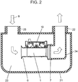
- FIG. 2 is a cross-sectional view illustrating a state in which ultrasonic flow rate measurement device 10 according to the invention is attached to meter body 21.
- Meter body 21 includes meter inlet port 25, meter outlet port 22, buffering part 23, and delivery pipe 24. Note that flow direction 9 indicated by the arrow is the direction in which the fluid to be measured flows.
- ultrasonic flow rate measurement device 10 is integrated inside meter body 21 having a substantially rectangular-parallelepiped shape.
- the inlet side, in which inlet-side rectification part 6 is disposed, of ultrasonic flow rate measurement device 10 opens onto buffering part 23 of meter body 21.
- delivery pipe 24 communicating with meter outlet port 22 of meter body 21 is hermetically joined to outlet-side coupling part 7 of ultrasonic flow rate measurement device 10.
- Meter inlet port 25 and meter outlet port 22 are disposed in the same face of meter body 21.
- the fluid to be measured flows from meter inlet port 25 into buffering part 23 inside the meter, as indicated by the arrow (flow direction 9 of the fluid to be measured). Then, the fluid to be measured flows, from inlet-side rectification part 6 disposed in ultrasonic flow rate measurement device 10, into measurement flow path 1, and is subjected to the flow rate measurement with ultrasonic vibrators 2 and 3, and measurement circuit 4. After that, the fluid to be measured is discharged from meter outlet port 22 via delivery pipe 24.
- FIG. 3 is a cross-sectional view illustrating an example that ultrasonic flow rate measurement device 10 according to the invention is attached to another meter body 31.
- meter inlet port 32 and meter outlet port 33 are linearly arranged.
- Meter outlet port 33 communicates with delivery pipe 34.
- ultrasonic flow rate measurement device 10 is hermetically coupled with delivery pipe 34. According to this configuration, it is possible to dispose ultrasonic flow rate measurement device 10 at a midpoint of straight-pipe-shaped piping.
- FIG. 4 is a cross-sectional view illustrating an example that ultrasonic flow rate measurement device 10 according to the first embodiment of the invention is attached to piping 51.
- outlet-side coupling part 7 of ultrasonic flow rate measurement device 10 is hermetically coupled with end portion 52 of piping 51. According to the configuration, it is possible to dispose ultrasonic flow rate measurement device 10 in order to measure the flow rate of a fluid flowing into piping 51.
- ultrasonic flow rate measurement device 10 allows one ultrasonic flow rate measurement device 10 to be coupled with meters or piping which has a wide variety of configurations.
- FIG. 5A is a plan view illustrating a configuration of ultrasonic flow rate measurement device 61 according to the first embodiment of the invention.
- FIG. 5B is a side-elevational view of the configuration.
- FIG. 5C is an elevation view of the configuration as viewed from the inlet side thereof.
- FIG. 5D is a partial cross-sectional view of region A in FIG. 5A .
- the flow-path cross section of measurement flow path 81 has a rectangular shape with narrow side dimension L and long side dimension M.
- a plurality of reflectors 11 are disposed (see FIGS. 5A and 5C ) such that the reflectors are in parallel with the long sides (the longitudinal direction in FIG. 5C ) of the cross section of measurement flow path 1, and are in parallel with flow direction 9.
- reflectors 11 With reflectors 11, it is possible to reduce the influence of a difference in propagation time between the ultrasonic wave that propagates in straight lines between ultrasonic vibrators 2 and 3 and the ultrasonic wave that propagates via reflection on the wall surfaces of measurement flow path 81. With this configuration, even if the distance between ultrasonic vibrators 2 and 3 is short, it is possible to secure required measurement accuracy. Moreover, even if the entire length of measurement flow path 81 is short, reflectors 11 can offer the effect of stabilizing the flow inside measurement flow path 81.
- the presence of reflectors 11 allows the configuration in which surroundings of the site, where the device is installed, hardly influence the measurement accuracy.
- inner peripheral surface 6a of inlet-side rectification part 6 is configured with a curved surface.
- the radius of the curved surface is R ⁇ L/2, where R is the radius of the curved surface and L is the narrow side dimension of the cross section of measurement flow path 81. That is, the opening of inlet-side rectification part 6 is configured with the curve that becomes wider outward, with the curve having a radius of not less than 1/2 of the width dimension of the narrow side of the cross section of measurement flow path 81.
- This configuration allows turbulence in measurement flow path 81 to hardly occur even when a large amount of flow flows into the flow path.
- the configuration of the opening described above allows stable measurement performance that is hardly influenced by the surroundings.
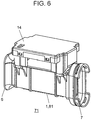
- FIG. 6 is a perspective view illustrating an appearance of ultrasonic flow rate measurement device 71 according to the second embodiment of the invention.
- each of the following components is totally configured with a resin, the components as follows: Measurement flow paths 1 and 81, inlet-side rectification part 6, outlet-side coupling part 7, and circuit case 14 that accommodates a measurement circuit.
- ultrasonic flow rate measurement devices 10 and 61 with the configurations described above, it is possible to reduce in size the whole of the device and to easily configure the shape thereof even with the resin, with a high degree of precision. Therefore, the whole of the device can be formed with the resin, which allows ultrasonic flow rate measurement device 71 that is further reduced in weight. Consequently, ultrasonic flow rate measurement device 71 allows easy installation thereof at a variety of sites.
- ultrasonic flowmeters are allowed which are capable of being easily integrated in a variety of piping and enclosures of meters, and capable of securing stable measurement accuracy.
- ultrasonic flow rate measurement devices 10, 61, and 71 can offer general versatility in installation thereof, and the measurement accuracy thereof is hardly influenced by surroundings of installation sites thereof. Consequently, the integration of ultrasonic flow rate measurement device 10, 61, or 71 allows the ultrasonic flowmeter capable of being tailored to a variety of the installation surroundings in a short development period of time, with an investment in the development and metal molds thereof being capped.
Landscapes
- Physics & Mathematics (AREA)
- Fluid Mechanics (AREA)
- General Physics & Mathematics (AREA)
- Electromagnetism (AREA)
- Measuring Volume Flow (AREA)
Applications Claiming Priority (2)
| Application Number | Priority Date | Filing Date | Title |
|---|---|---|---|
| JP2010251466A JP2012103087A (ja) | 2010-11-10 | 2010-11-10 | 超音波流量計測ユニット |
| PCT/JP2011/006135 WO2012063437A1 (ja) | 2010-11-10 | 2011-11-02 | 超音波流量計測装置 |
Publications (3)
| Publication Number | Publication Date |
|---|---|
| EP2639560A1 EP2639560A1 (en) | 2013-09-18 |
| EP2639560A4 EP2639560A4 (en) | 2014-07-09 |
| EP2639560B1 true EP2639560B1 (en) | 2019-03-06 |
Family
ID=46050606
Family Applications (1)
| Application Number | Title | Priority Date | Filing Date |
|---|---|---|---|
| EP11840044.9A Active EP2639560B1 (en) | 2010-11-10 | 2011-11-02 | Ultrasonic flow rate measurement device |
Country Status (5)
| Country | Link |
|---|---|
| US (1) | US8984960B2 (ja) |
| EP (1) | EP2639560B1 (ja) |
| JP (1) | JP2012103087A (ja) |
| CN (1) | CN103201599B (ja) |
| WO (1) | WO2012063437A1 (ja) |
Cited By (1)
| Publication number | Priority date | Publication date | Assignee | Title |
|---|---|---|---|---|
| RU2796499C1 (ru) * | 2022-11-25 | 2023-05-24 | Акционерное общество "Научно-производственное объединение "Радиозавод имени А.С. Попова" | Ультразвуковой расходомер газа |
Families Citing this family (28)
| Publication number | Priority date | Publication date | Assignee | Title |
|---|---|---|---|---|
| US8671774B2 (en) * | 2009-10-01 | 2014-03-18 | Panasonic Corporation | Ultrasonic flow meter unit |
| JP2014077750A (ja) * | 2012-10-12 | 2014-05-01 | Panasonic Corp | 超音波メータ |
| JP6060378B2 (ja) * | 2012-11-13 | 2017-01-18 | パナソニックIpマネジメント株式会社 | 流量計測装置 |
| CN103035070B (zh) * | 2012-12-12 | 2014-09-03 | 山东冠翔仪表有限公司 | 小口径超声波智能水表 |
| JP6313048B2 (ja) * | 2014-01-09 | 2018-04-18 | パナソニック株式会社 | 計測ユニットおよびそれを備えた流量計測装置 |
| JP6330141B2 (ja) * | 2014-02-07 | 2018-05-30 | パナソニックIpマネジメント株式会社 | ガス流量計 |
| CN104075758A (zh) * | 2014-06-09 | 2014-10-01 | 沈阳市航宇星仪表有限责任公司 | 超声波燃气表整流单元流道装置 |
| CN105043474A (zh) * | 2015-06-03 | 2015-11-11 | 成都千嘉科技有限公司 | 一种用于超声波流量计的新型流道结构 |
| US9618372B2 (en) * | 2015-09-04 | 2017-04-11 | Onicon Inc. | Transit time flow meter probe |
| JP6375519B2 (ja) | 2016-01-12 | 2018-08-22 | パナソニックIpマネジメント株式会社 | ガスメータ |
| US10222247B2 (en) * | 2016-07-07 | 2019-03-05 | Joseph Baumoel | Multiphase ultrasonic flow meter |
| US10746580B2 (en) * | 2016-07-13 | 2020-08-18 | Gwf Messsysteme Ag | Flow meter with measuring channel |
| JP2018194506A (ja) * | 2017-05-22 | 2018-12-06 | パナソニックIpマネジメント株式会社 | 流量計測ユニット及びこれを用いたガスメータ |
| JP2018194508A (ja) * | 2017-05-22 | 2018-12-06 | パナソニックIpマネジメント株式会社 | ガスメータ |
| JP2018194507A (ja) * | 2017-05-22 | 2018-12-06 | パナソニックIpマネジメント株式会社 | ガスメータ |
| WO2018216482A1 (ja) * | 2017-05-22 | 2018-11-29 | パナソニックIpマネジメント株式会社 | ガスメータ |
| JP2018194505A (ja) * | 2017-05-22 | 2018-12-06 | パナソニックIpマネジメント株式会社 | 流量計測ユニット及びこれを用いたガスメータ |
| US10576978B2 (en) * | 2017-12-06 | 2020-03-03 | Cummins, Inc. | System and method for predictive engine and aftertreatment system control |
| US10473502B2 (en) | 2018-03-01 | 2019-11-12 | Joseph Baumoel | Dielectric multiphase flow meter |
| CN108414037A (zh) * | 2018-03-28 | 2018-08-17 | 上海中核维思仪器仪表有限公司 | 气体超声流量计测速流道 |
| CN108871475A (zh) * | 2018-05-04 | 2018-11-23 | 金卡智能集团股份有限公司 | 超声波计量装置 |
| DE102019008902A1 (de) * | 2018-12-28 | 2020-07-02 | Marquardt Gmbh | Baueinheit für eine Fluid-Leitung |
| CN109752056A (zh) * | 2018-12-29 | 2019-05-14 | 杭州先锋电子技术股份有限公司 | 一种超声波气体计量装置的流道结构及超声波计量表 |
| CN110988115A (zh) | 2019-12-26 | 2020-04-10 | 湖北锐意自控系统有限公司 | 一种超声波气体传感器 |
| CN113295222A (zh) * | 2020-02-21 | 2021-08-24 | 北京昌民技术有限公司 | 超声波流量计 |
| US11906338B2 (en) | 2020-06-05 | 2024-02-20 | Honeywell International Inc. | Flow measurement by combining 3L echo with delta time-of-flight cross correlation |
| EP4204770A1 (de) | 2020-10-14 | 2023-07-05 | Gwf Ag | Durchflussmesser |
| CN114323174B (zh) * | 2021-11-25 | 2023-06-06 | 山东大卫国际建筑设计有限公司 | 一种超声波流量计 |
Citations (2)
| Publication number | Priority date | Publication date | Assignee | Title |
|---|---|---|---|---|
| WO1999047896A1 (fr) * | 1998-03-19 | 1999-09-23 | Schlumberger Industries, S.A. | Compteur de gaz a filtres anti-poussieres |
| DE102006023479A1 (de) * | 2006-05-18 | 2007-11-22 | Siemens Ag | Strömungskanal zur Aufnahme des Durchflusssensors |
Family Cites Families (17)
| Publication number | Priority date | Publication date | Assignee | Title |
|---|---|---|---|---|
| GB2043900B (en) * | 1979-02-27 | 1983-05-11 | Rolfe P | Flowmeter |
| JPH09189591A (ja) * | 1996-01-10 | 1997-07-22 | Kaijo Corp | 流体測定装置 |
| US6026693A (en) * | 1997-06-04 | 2000-02-22 | Baumoel; Douglas S. | Pipe spool section having square or rectangular cross-section for clamp on transducer and method for flow measurement |
| JP3217021B2 (ja) * | 1998-01-16 | 2001-10-09 | 経済産業省産業技術総合研究所長 | 超音波流量計 |
| JP2000146645A (ja) * | 1998-11-12 | 2000-05-26 | Honda Electronic Co Ltd | 超音波流量計 |
| US7237441B2 (en) * | 2003-02-24 | 2007-07-03 | Matsushita Electric Industrial Co., Ltd. | Ultrasonic type fluid measurement device |
| DE102004060065B4 (de) * | 2004-12-14 | 2016-10-20 | Robert Bosch Gmbh | Ultraschall Durchflussmesser mit Leitelementen |
| DE102006030942A1 (de) * | 2006-07-05 | 2008-01-10 | Landis+Gyr Gmbh | Durchflussmesser mit einem Einlaufbereich und einer Durchflussmessstrecke |
| JP5041847B2 (ja) * | 2007-03-30 | 2012-10-03 | 旭有機材工業株式会社 | 流体制御装置 |
| JP5236303B2 (ja) | 2008-02-08 | 2013-07-17 | 東洋ガスメーター株式会社 | ガスメータ |
| JP5259313B2 (ja) * | 2008-09-09 | 2013-08-07 | 東京瓦斯株式会社 | 超音波流量計 |
| WO2010070891A1 (ja) * | 2008-12-18 | 2010-06-24 | パナソニック株式会社 | 超音波式流量計 |
| JP2012021782A (ja) * | 2010-07-12 | 2012-02-02 | Panasonic Corp | 超音波流量計測ユニット |
| JP2012132801A (ja) * | 2010-12-22 | 2012-07-12 | Panasonic Corp | 超音波流量計 |
| JP4878653B1 (ja) * | 2011-01-28 | 2012-02-15 | 株式会社アツデン | 超音波流量測定装置 |
| WO2012137489A1 (ja) * | 2011-04-05 | 2012-10-11 | パナソニック株式会社 | 超音波流量計測装置 |
| JP4991963B1 (ja) * | 2011-11-16 | 2012-08-08 | 株式会社アツデン | 超音波式流量測定装置及びその使用方法 |
-
2010
- 2010-11-10 JP JP2010251466A patent/JP2012103087A/ja active Pending
-
2011
- 2011-11-02 WO PCT/JP2011/006135 patent/WO2012063437A1/ja active Application Filing
- 2011-11-02 CN CN201180054446.7A patent/CN103201599B/zh active Active
- 2011-11-02 US US13/821,915 patent/US8984960B2/en active Active
- 2011-11-02 EP EP11840044.9A patent/EP2639560B1/en active Active
Patent Citations (2)
| Publication number | Priority date | Publication date | Assignee | Title |
|---|---|---|---|---|
| WO1999047896A1 (fr) * | 1998-03-19 | 1999-09-23 | Schlumberger Industries, S.A. | Compteur de gaz a filtres anti-poussieres |
| DE102006023479A1 (de) * | 2006-05-18 | 2007-11-22 | Siemens Ag | Strömungskanal zur Aufnahme des Durchflusssensors |
Cited By (1)
| Publication number | Priority date | Publication date | Assignee | Title |
|---|---|---|---|---|
| RU2796499C1 (ru) * | 2022-11-25 | 2023-05-24 | Акционерное общество "Научно-производственное объединение "Радиозавод имени А.С. Попова" | Ультразвуковой расходомер газа |
Also Published As
| Publication number | Publication date |
|---|---|
| CN103201599A (zh) | 2013-07-10 |
| WO2012063437A1 (ja) | 2012-05-18 |
| US8984960B2 (en) | 2015-03-24 |
| EP2639560A4 (en) | 2014-07-09 |
| CN103201599B (zh) | 2015-08-19 |
| US20130167655A1 (en) | 2013-07-04 |
| JP2012103087A (ja) | 2012-05-31 |
| EP2639560A1 (en) | 2013-09-18 |
Similar Documents
| Publication | Publication Date | Title |
|---|---|---|
| EP2639560B1 (en) | Ultrasonic flow rate measurement device | |
| JP2010164558A (ja) | 流体の流れ計測装置 | |
| JPH08285647A (ja) | 超音波流量計用検出器 | |
| EP2485016B1 (en) | Ultrasonic flow rate measuring unit | |
| EP1742024B1 (en) | Ultrasonic flowmeter with triangular cross section | |
| CN110553690B (zh) | 流体测量装置和用于流体测量装置的流体测量模块及组件 | |
| US20210080302A1 (en) | Ultrasonic Meter | |
| US20200386590A1 (en) | Ultrasonic Flowmeter Element | |
| EP2485017A1 (en) | Ultrasonic flowmeter | |
| JP6375519B2 (ja) | ガスメータ | |
| CN106030254A (zh) | 气体流量计 | |
| JP4936856B2 (ja) | 流量計 | |
| JP5259313B2 (ja) | 超音波流量計 | |
| US11385085B2 (en) | Ultrasonic flowmeter | |
| JP2005189090A (ja) | 超音波式水道メータ | |
| JP6134899B2 (ja) | 流量計測ユニット | |
| JP2014077750A (ja) | 超音波メータ | |
| TW202219468A (zh) | 超音波流量測量裝置 | |
| KR100861827B1 (ko) | 초음파 유량계와 그 제조 방법 | |
| CN111272240A (zh) | 一种内置式斜反射多声道超声波流量测量模块及流量计 | |
| JP4453341B2 (ja) | 超音波流量計 | |
| JP2008014829A (ja) | 超音波流量計 | |
| JP7373771B2 (ja) | 物理量計測装置 | |
| US20240077344A1 (en) | Integrated enclosure for ultrasonic flowmeter | |
| CN108700447B (zh) | 气量计 |
Legal Events
| Date | Code | Title | Description |
|---|---|---|---|
| PUAI | Public reference made under article 153(3) epc to a published international application that has entered the european phase |
Free format text: ORIGINAL CODE: 0009012 |
|
| 17P | Request for examination filed |
Effective date: 20130412 |
|
| AK | Designated contracting states |
Kind code of ref document: A1 Designated state(s): AL AT BE BG CH CY CZ DE DK EE ES FI FR GB GR HR HU IE IS IT LI LT LU LV MC MK MT NL NO PL PT RO RS SE SI SK SM TR |
|
| DAX | Request for extension of the european patent (deleted) | ||
| A4 | Supplementary search report drawn up and despatched |
Effective date: 20140605 |
|
| RIC1 | Information provided on ipc code assigned before grant |
Ipc: G01F 1/66 20060101AFI20140530BHEP Ipc: G01F 15/18 20060101ALN20140530BHEP |
|
| 17Q | First examination report despatched |
Effective date: 20160128 |
|
| STAA | Information on the status of an ep patent application or granted ep patent |
Free format text: STATUS: EXAMINATION IS IN PROGRESS |
|
| GRAP | Despatch of communication of intention to grant a patent |
Free format text: ORIGINAL CODE: EPIDOSNIGR1 |
|
| RIC1 | Information provided on ipc code assigned before grant |
Ipc: G01F 15/18 20060101ALN20181012BHEP Ipc: G01F 1/66 20060101AFI20181012BHEP |
|
| STAA | Information on the status of an ep patent application or granted ep patent |
Free format text: STATUS: GRANT OF PATENT IS INTENDED |
|
| RIC1 | Information provided on ipc code assigned before grant |
Ipc: G01F 1/66 20060101AFI20181107BHEP Ipc: G01F 15/18 20060101ALN20181107BHEP |
|
| INTG | Intention to grant announced |
Effective date: 20181122 |
|
| RIN1 | Information on inventor provided before grant (corrected) |
Inventor name: GOTOU, HIROKAZU Inventor name: FUJII, YUJI Inventor name: OZAKI, YUKINORI Inventor name: SATOU, MASATO |
|
| GRAS | Grant fee paid |
Free format text: ORIGINAL CODE: EPIDOSNIGR3 |
|
| GRAA | (expected) grant |
Free format text: ORIGINAL CODE: 0009210 |
|
| STAA | Information on the status of an ep patent application or granted ep patent |
Free format text: STATUS: THE PATENT HAS BEEN GRANTED |
|
| AK | Designated contracting states |
Kind code of ref document: B1 Designated state(s): AL AT BE BG CH CY CZ DE DK EE ES FI FR GB GR HR HU IE IS IT LI LT LU LV MC MK MT NL NO PL PT RO RS SE SI SK SM TR |
|
| REG | Reference to a national code |
Ref country code: GB Ref legal event code: FG4D |
|
| REG | Reference to a national code |
Ref country code: CH Ref legal event code: EP Ref country code: AT Ref legal event code: REF Ref document number: 1105177 Country of ref document: AT Kind code of ref document: T Effective date: 20190315 |
|
| REG | Reference to a national code |
Ref country code: DE Ref legal event code: R096 Ref document number: 602011056980 Country of ref document: DE |
|
| REG | Reference to a national code |
Ref country code: IE Ref legal event code: FG4D |
|
| REG | Reference to a national code |
Ref country code: NL Ref legal event code: MP Effective date: 20190306 |
|
| REG | Reference to a national code |
Ref country code: LT Ref legal event code: MG4D |
|
| PG25 | Lapsed in a contracting state [announced via postgrant information from national office to epo] |
Ref country code: FI Free format text: LAPSE BECAUSE OF FAILURE TO SUBMIT A TRANSLATION OF THE DESCRIPTION OR TO PAY THE FEE WITHIN THE PRESCRIBED TIME-LIMIT Effective date: 20190306 Ref country code: SE Free format text: LAPSE BECAUSE OF FAILURE TO SUBMIT A TRANSLATION OF THE DESCRIPTION OR TO PAY THE FEE WITHIN THE PRESCRIBED TIME-LIMIT Effective date: 20190306 Ref country code: LT Free format text: LAPSE BECAUSE OF FAILURE TO SUBMIT A TRANSLATION OF THE DESCRIPTION OR TO PAY THE FEE WITHIN THE PRESCRIBED TIME-LIMIT Effective date: 20190306 Ref country code: NO Free format text: LAPSE BECAUSE OF FAILURE TO SUBMIT A TRANSLATION OF THE DESCRIPTION OR TO PAY THE FEE WITHIN THE PRESCRIBED TIME-LIMIT Effective date: 20190606 |
|
| PG25 | Lapsed in a contracting state [announced via postgrant information from national office to epo] |
Ref country code: NL Free format text: LAPSE BECAUSE OF FAILURE TO SUBMIT A TRANSLATION OF THE DESCRIPTION OR TO PAY THE FEE WITHIN THE PRESCRIBED TIME-LIMIT Effective date: 20190306 Ref country code: LV Free format text: LAPSE BECAUSE OF FAILURE TO SUBMIT A TRANSLATION OF THE DESCRIPTION OR TO PAY THE FEE WITHIN THE PRESCRIBED TIME-LIMIT Effective date: 20190306 Ref country code: RS Free format text: LAPSE BECAUSE OF FAILURE TO SUBMIT A TRANSLATION OF THE DESCRIPTION OR TO PAY THE FEE WITHIN THE PRESCRIBED TIME-LIMIT Effective date: 20190306 Ref country code: HR Free format text: LAPSE BECAUSE OF FAILURE TO SUBMIT A TRANSLATION OF THE DESCRIPTION OR TO PAY THE FEE WITHIN THE PRESCRIBED TIME-LIMIT Effective date: 20190306 Ref country code: GR Free format text: LAPSE BECAUSE OF FAILURE TO SUBMIT A TRANSLATION OF THE DESCRIPTION OR TO PAY THE FEE WITHIN THE PRESCRIBED TIME-LIMIT Effective date: 20190607 Ref country code: BG Free format text: LAPSE BECAUSE OF FAILURE TO SUBMIT A TRANSLATION OF THE DESCRIPTION OR TO PAY THE FEE WITHIN THE PRESCRIBED TIME-LIMIT Effective date: 20190606 |
|
| REG | Reference to a national code |
Ref country code: AT Ref legal event code: MK05 Ref document number: 1105177 Country of ref document: AT Kind code of ref document: T Effective date: 20190306 |
|
| PG25 | Lapsed in a contracting state [announced via postgrant information from national office to epo] |
Ref country code: EE Free format text: LAPSE BECAUSE OF FAILURE TO SUBMIT A TRANSLATION OF THE DESCRIPTION OR TO PAY THE FEE WITHIN THE PRESCRIBED TIME-LIMIT Effective date: 20190306 Ref country code: ES Free format text: LAPSE BECAUSE OF FAILURE TO SUBMIT A TRANSLATION OF THE DESCRIPTION OR TO PAY THE FEE WITHIN THE PRESCRIBED TIME-LIMIT Effective date: 20190306 Ref country code: RO Free format text: LAPSE BECAUSE OF FAILURE TO SUBMIT A TRANSLATION OF THE DESCRIPTION OR TO PAY THE FEE WITHIN THE PRESCRIBED TIME-LIMIT Effective date: 20190306 Ref country code: CZ Free format text: LAPSE BECAUSE OF FAILURE TO SUBMIT A TRANSLATION OF THE DESCRIPTION OR TO PAY THE FEE WITHIN THE PRESCRIBED TIME-LIMIT Effective date: 20190306 Ref country code: SK Free format text: LAPSE BECAUSE OF FAILURE TO SUBMIT A TRANSLATION OF THE DESCRIPTION OR TO PAY THE FEE WITHIN THE PRESCRIBED TIME-LIMIT Effective date: 20190306 Ref country code: PT Free format text: LAPSE BECAUSE OF FAILURE TO SUBMIT A TRANSLATION OF THE DESCRIPTION OR TO PAY THE FEE WITHIN THE PRESCRIBED TIME-LIMIT Effective date: 20190706 Ref country code: AL Free format text: LAPSE BECAUSE OF FAILURE TO SUBMIT A TRANSLATION OF THE DESCRIPTION OR TO PAY THE FEE WITHIN THE PRESCRIBED TIME-LIMIT Effective date: 20190306 |
|
| PG25 | Lapsed in a contracting state [announced via postgrant information from national office to epo] |
Ref country code: PL Free format text: LAPSE BECAUSE OF FAILURE TO SUBMIT A TRANSLATION OF THE DESCRIPTION OR TO PAY THE FEE WITHIN THE PRESCRIBED TIME-LIMIT Effective date: 20190306 Ref country code: SM Free format text: LAPSE BECAUSE OF FAILURE TO SUBMIT A TRANSLATION OF THE DESCRIPTION OR TO PAY THE FEE WITHIN THE PRESCRIBED TIME-LIMIT Effective date: 20190306 |
|
| REG | Reference to a national code |
Ref country code: DE Ref legal event code: R097 Ref document number: 602011056980 Country of ref document: DE |
|
| PG25 | Lapsed in a contracting state [announced via postgrant information from national office to epo] |
Ref country code: AT Free format text: LAPSE BECAUSE OF FAILURE TO SUBMIT A TRANSLATION OF THE DESCRIPTION OR TO PAY THE FEE WITHIN THE PRESCRIBED TIME-LIMIT Effective date: 20190306 Ref country code: IS Free format text: LAPSE BECAUSE OF FAILURE TO SUBMIT A TRANSLATION OF THE DESCRIPTION OR TO PAY THE FEE WITHIN THE PRESCRIBED TIME-LIMIT Effective date: 20190706 |
|
| PLBE | No opposition filed within time limit |
Free format text: ORIGINAL CODE: 0009261 |
|
| STAA | Information on the status of an ep patent application or granted ep patent |
Free format text: STATUS: NO OPPOSITION FILED WITHIN TIME LIMIT |
|
| PG25 | Lapsed in a contracting state [announced via postgrant information from national office to epo] |
Ref country code: DK Free format text: LAPSE BECAUSE OF FAILURE TO SUBMIT A TRANSLATION OF THE DESCRIPTION OR TO PAY THE FEE WITHIN THE PRESCRIBED TIME-LIMIT Effective date: 20190306 |
|
| 26N | No opposition filed |
Effective date: 20191209 |
|
| PG25 | Lapsed in a contracting state [announced via postgrant information from national office to epo] |
Ref country code: SI Free format text: LAPSE BECAUSE OF FAILURE TO SUBMIT A TRANSLATION OF THE DESCRIPTION OR TO PAY THE FEE WITHIN THE PRESCRIBED TIME-LIMIT Effective date: 20190306 |
|
| PG25 | Lapsed in a contracting state [announced via postgrant information from national office to epo] |
Ref country code: TR Free format text: LAPSE BECAUSE OF FAILURE TO SUBMIT A TRANSLATION OF THE DESCRIPTION OR TO PAY THE FEE WITHIN THE PRESCRIBED TIME-LIMIT Effective date: 20190306 |
|
| REG | Reference to a national code |
Ref country code: CH Ref legal event code: PL |
|
| PG25 | Lapsed in a contracting state [announced via postgrant information from national office to epo] |
Ref country code: CH Free format text: LAPSE BECAUSE OF NON-PAYMENT OF DUE FEES Effective date: 20191130 Ref country code: LI Free format text: LAPSE BECAUSE OF NON-PAYMENT OF DUE FEES Effective date: 20191130 Ref country code: MC Free format text: LAPSE BECAUSE OF FAILURE TO SUBMIT A TRANSLATION OF THE DESCRIPTION OR TO PAY THE FEE WITHIN THE PRESCRIBED TIME-LIMIT Effective date: 20190306 Ref country code: LU Free format text: LAPSE BECAUSE OF NON-PAYMENT OF DUE FEES Effective date: 20191102 |
|
| REG | Reference to a national code |
Ref country code: BE Ref legal event code: MM Effective date: 20191130 |
|
| PG25 | Lapsed in a contracting state [announced via postgrant information from national office to epo] |
Ref country code: IE Free format text: LAPSE BECAUSE OF NON-PAYMENT OF DUE FEES Effective date: 20191102 |
|
| PG25 | Lapsed in a contracting state [announced via postgrant information from national office to epo] |
Ref country code: BE Free format text: LAPSE BECAUSE OF NON-PAYMENT OF DUE FEES Effective date: 20191130 |
|
| PG25 | Lapsed in a contracting state [announced via postgrant information from national office to epo] |
Ref country code: CY Free format text: LAPSE BECAUSE OF FAILURE TO SUBMIT A TRANSLATION OF THE DESCRIPTION OR TO PAY THE FEE WITHIN THE PRESCRIBED TIME-LIMIT Effective date: 20190306 |
|
| PG25 | Lapsed in a contracting state [announced via postgrant information from national office to epo] |
Ref country code: MT Free format text: LAPSE BECAUSE OF FAILURE TO SUBMIT A TRANSLATION OF THE DESCRIPTION OR TO PAY THE FEE WITHIN THE PRESCRIBED TIME-LIMIT Effective date: 20190306 Ref country code: HU Free format text: LAPSE BECAUSE OF FAILURE TO SUBMIT A TRANSLATION OF THE DESCRIPTION OR TO PAY THE FEE WITHIN THE PRESCRIBED TIME-LIMIT; INVALID AB INITIO Effective date: 20111102 |
|
| PG25 | Lapsed in a contracting state [announced via postgrant information from national office to epo] |
Ref country code: MK Free format text: LAPSE BECAUSE OF FAILURE TO SUBMIT A TRANSLATION OF THE DESCRIPTION OR TO PAY THE FEE WITHIN THE PRESCRIBED TIME-LIMIT Effective date: 20190306 |
|
| PGFP | Annual fee paid to national office [announced via postgrant information from national office to epo] |
Ref country code: GB Payment date: 20231123 Year of fee payment: 13 |
|
| PGFP | Annual fee paid to national office [announced via postgrant information from national office to epo] |
Ref country code: IT Payment date: 20231124 Year of fee payment: 13 Ref country code: FR Payment date: 20231120 Year of fee payment: 13 Ref country code: DE Payment date: 20231121 Year of fee payment: 13 |