EP2639175B1 - Stapelbehältersystem - Google Patents
Stapelbehältersystem Download PDFInfo
- Publication number
- EP2639175B1 EP2639175B1 EP12159064.0A EP12159064A EP2639175B1 EP 2639175 B1 EP2639175 B1 EP 2639175B1 EP 12159064 A EP12159064 A EP 12159064A EP 2639175 B1 EP2639175 B1 EP 2639175B1
- Authority
- EP
- European Patent Office
- Prior art keywords
- container
- lid
- stacking
- elements
- locking
- Prior art date
- Legal status (The legal status is an assumption and is not a legal conclusion. Google has not performed a legal analysis and makes no representation as to the accuracy of the status listed.)
- Active
Links
Images


Classifications
-
- B—PERFORMING OPERATIONS; TRANSPORTING
- B65—CONVEYING; PACKING; STORING; HANDLING THIN OR FILAMENTARY MATERIAL
- B65D—CONTAINERS FOR STORAGE OR TRANSPORT OF ARTICLES OR MATERIALS, e.g. BAGS, BARRELS, BOTTLES, BOXES, CANS, CARTONS, CRATES, DRUMS, JARS, TANKS, HOPPERS, FORWARDING CONTAINERS; ACCESSORIES, CLOSURES, OR FITTINGS THEREFOR; PACKAGING ELEMENTS; PACKAGES
- B65D21/00—Nestable, stackable or joinable containers; Containers of variable capacity
- B65D21/02—Containers specially shaped, or provided with fittings or attachments, to facilitate nesting, stacking, or joining together
- B65D21/0209—Containers specially shaped, or provided with fittings or attachments, to facilitate nesting, stacking, or joining together stackable or joined together one-upon-the-other in the upright or upside-down position
- B65D21/0217—Containers with a closure presenting stacking elements
- B65D21/0223—Containers with a closure presenting stacking elements the closure and the bottom presenting local co-operating elements, e.g. projections and recesses
-
- B—PERFORMING OPERATIONS; TRANSPORTING
- B65—CONVEYING; PACKING; STORING; HANDLING THIN OR FILAMENTARY MATERIAL
- B65D—CONTAINERS FOR STORAGE OR TRANSPORT OF ARTICLES OR MATERIALS, e.g. BAGS, BARRELS, BOTTLES, BOXES, CANS, CARTONS, CRATES, DRUMS, JARS, TANKS, HOPPERS, FORWARDING CONTAINERS; ACCESSORIES, CLOSURES, OR FITTINGS THEREFOR; PACKAGING ELEMENTS; PACKAGES
- B65D21/00—Nestable, stackable or joinable containers; Containers of variable capacity
- B65D21/02—Containers specially shaped, or provided with fittings or attachments, to facilitate nesting, stacking, or joining together
- B65D21/0209—Containers specially shaped, or provided with fittings or attachments, to facilitate nesting, stacking, or joining together stackable or joined together one-upon-the-other in the upright or upside-down position
- B65D21/0213—Containers presenting a continuous stacking profile along the upper or lower edge of at least two opposite side walls
-
- B—PERFORMING OPERATIONS; TRANSPORTING
- B65—CONVEYING; PACKING; STORING; HANDLING THIN OR FILAMENTARY MATERIAL
- B65D—CONTAINERS FOR STORAGE OR TRANSPORT OF ARTICLES OR MATERIALS, e.g. BAGS, BARRELS, BOTTLES, BOXES, CANS, CARTONS, CRATES, DRUMS, JARS, TANKS, HOPPERS, FORWARDING CONTAINERS; ACCESSORIES, CLOSURES, OR FITTINGS THEREFOR; PACKAGING ELEMENTS; PACKAGES
- B65D43/00—Lids or covers for rigid or semi-rigid containers
- B65D43/02—Removable lids or covers
- B65D43/0202—Removable lids or covers without integral tamper element
- B65D43/0204—Removable lids or covers without integral tamper element secured by snapping over beads or projections
- B65D43/0208—Removable lids or covers without integral tamper element secured by snapping over beads or projections on both the inside and the outside of the mouth of the container
-
- B—PERFORMING OPERATIONS; TRANSPORTING
- B65—CONVEYING; PACKING; STORING; HANDLING THIN OR FILAMENTARY MATERIAL
- B65D—CONTAINERS FOR STORAGE OR TRANSPORT OF ARTICLES OR MATERIALS, e.g. BAGS, BARRELS, BOTTLES, BOXES, CANS, CARTONS, CRATES, DRUMS, JARS, TANKS, HOPPERS, FORWARDING CONTAINERS; ACCESSORIES, CLOSURES, OR FITTINGS THEREFOR; PACKAGING ELEMENTS; PACKAGES
- B65D2543/00—Lids or covers essentially for box-like containers
- B65D2543/00009—Details of lids or covers for rigid or semi-rigid containers
- B65D2543/00018—Overall construction of the lid
- B65D2543/00027—Stackable lids or covers
-
- B—PERFORMING OPERATIONS; TRANSPORTING
- B65—CONVEYING; PACKING; STORING; HANDLING THIN OR FILAMENTARY MATERIAL
- B65D—CONTAINERS FOR STORAGE OR TRANSPORT OF ARTICLES OR MATERIALS, e.g. BAGS, BARRELS, BOTTLES, BOXES, CANS, CARTONS, CRATES, DRUMS, JARS, TANKS, HOPPERS, FORWARDING CONTAINERS; ACCESSORIES, CLOSURES, OR FITTINGS THEREFOR; PACKAGING ELEMENTS; PACKAGES
- B65D2543/00—Lids or covers essentially for box-like containers
- B65D2543/00009—Details of lids or covers for rigid or semi-rigid containers
- B65D2543/00018—Overall construction of the lid
- B65D2543/00064—Shape of the outer periphery
- B65D2543/0012—Shape of the outer periphery having straight sides, e.g. with curved corners
- B65D2543/00175—Shape of the outer periphery having straight sides, e.g. with curved corners four straight sides, e.g. trapezium or diamond
- B65D2543/00194—Shape of the outer periphery having straight sides, e.g. with curved corners four straight sides, e.g. trapezium or diamond square or rectangular
-
- B—PERFORMING OPERATIONS; TRANSPORTING
- B65—CONVEYING; PACKING; STORING; HANDLING THIN OR FILAMENTARY MATERIAL
- B65D—CONTAINERS FOR STORAGE OR TRANSPORT OF ARTICLES OR MATERIALS, e.g. BAGS, BARRELS, BOTTLES, BOXES, CANS, CARTONS, CRATES, DRUMS, JARS, TANKS, HOPPERS, FORWARDING CONTAINERS; ACCESSORIES, CLOSURES, OR FITTINGS THEREFOR; PACKAGING ELEMENTS; PACKAGES
- B65D2543/00—Lids or covers essentially for box-like containers
- B65D2543/00009—Details of lids or covers for rigid or semi-rigid containers
- B65D2543/00018—Overall construction of the lid
- B65D2543/00259—Materials used
- B65D2543/00296—Plastic
-
- B—PERFORMING OPERATIONS; TRANSPORTING
- B65—CONVEYING; PACKING; STORING; HANDLING THIN OR FILAMENTARY MATERIAL
- B65D—CONTAINERS FOR STORAGE OR TRANSPORT OF ARTICLES OR MATERIALS, e.g. BAGS, BARRELS, BOTTLES, BOXES, CANS, CARTONS, CRATES, DRUMS, JARS, TANKS, HOPPERS, FORWARDING CONTAINERS; ACCESSORIES, CLOSURES, OR FITTINGS THEREFOR; PACKAGING ELEMENTS; PACKAGES
- B65D2543/00—Lids or covers essentially for box-like containers
- B65D2543/00009—Details of lids or covers for rigid or semi-rigid containers
- B65D2543/00444—Contact between the container and the lid
- B65D2543/00481—Contact between the container and the lid on the inside or the outside of the container
- B65D2543/00555—Contact between the container and the lid on the inside or the outside of the container on both the inside and the outside
-
- B—PERFORMING OPERATIONS; TRANSPORTING
- B65—CONVEYING; PACKING; STORING; HANDLING THIN OR FILAMENTARY MATERIAL
- B65D—CONTAINERS FOR STORAGE OR TRANSPORT OF ARTICLES OR MATERIALS, e.g. BAGS, BARRELS, BOTTLES, BOXES, CANS, CARTONS, CRATES, DRUMS, JARS, TANKS, HOPPERS, FORWARDING CONTAINERS; ACCESSORIES, CLOSURES, OR FITTINGS THEREFOR; PACKAGING ELEMENTS; PACKAGES
- B65D2543/00—Lids or covers essentially for box-like containers
- B65D2543/00009—Details of lids or covers for rigid or semi-rigid containers
- B65D2543/00444—Contact between the container and the lid
- B65D2543/00592—Snapping means
- B65D2543/00601—Snapping means on the container
- B65D2543/00611—Profiles
- B65D2543/00648—Flange or lip
-
- B—PERFORMING OPERATIONS; TRANSPORTING
- B65—CONVEYING; PACKING; STORING; HANDLING THIN OR FILAMENTARY MATERIAL
- B65D—CONTAINERS FOR STORAGE OR TRANSPORT OF ARTICLES OR MATERIALS, e.g. BAGS, BARRELS, BOTTLES, BOXES, CANS, CARTONS, CRATES, DRUMS, JARS, TANKS, HOPPERS, FORWARDING CONTAINERS; ACCESSORIES, CLOSURES, OR FITTINGS THEREFOR; PACKAGING ELEMENTS; PACKAGES
- B65D2543/00—Lids or covers essentially for box-like containers
- B65D2543/00009—Details of lids or covers for rigid or semi-rigid containers
- B65D2543/00444—Contact between the container and the lid
- B65D2543/00592—Snapping means
- B65D2543/00601—Snapping means on the container
- B65D2543/00675—Periphery concerned
- B65D2543/00694—Segments
-
- B—PERFORMING OPERATIONS; TRANSPORTING
- B65—CONVEYING; PACKING; STORING; HANDLING THIN OR FILAMENTARY MATERIAL
- B65D—CONTAINERS FOR STORAGE OR TRANSPORT OF ARTICLES OR MATERIALS, e.g. BAGS, BARRELS, BOTTLES, BOXES, CANS, CARTONS, CRATES, DRUMS, JARS, TANKS, HOPPERS, FORWARDING CONTAINERS; ACCESSORIES, CLOSURES, OR FITTINGS THEREFOR; PACKAGING ELEMENTS; PACKAGES
- B65D2543/00—Lids or covers essentially for box-like containers
- B65D2543/00009—Details of lids or covers for rigid or semi-rigid containers
- B65D2543/00444—Contact between the container and the lid
- B65D2543/00592—Snapping means
- B65D2543/00712—Snapping means on the lid
- B65D2543/00722—Profiles
- B65D2543/00768—U-shaped or inverted U
-
- B—PERFORMING OPERATIONS; TRANSPORTING
- B65—CONVEYING; PACKING; STORING; HANDLING THIN OR FILAMENTARY MATERIAL
- B65D—CONTAINERS FOR STORAGE OR TRANSPORT OF ARTICLES OR MATERIALS, e.g. BAGS, BARRELS, BOTTLES, BOXES, CANS, CARTONS, CRATES, DRUMS, JARS, TANKS, HOPPERS, FORWARDING CONTAINERS; ACCESSORIES, CLOSURES, OR FITTINGS THEREFOR; PACKAGING ELEMENTS; PACKAGES
- B65D2543/00—Lids or covers essentially for box-like containers
- B65D2543/00009—Details of lids or covers for rigid or semi-rigid containers
- B65D2543/00444—Contact between the container and the lid
- B65D2543/00592—Snapping means
- B65D2543/00712—Snapping means on the lid
- B65D2543/00787—Periphery concerned
- B65D2543/00805—Segments
-
- B—PERFORMING OPERATIONS; TRANSPORTING
- B65—CONVEYING; PACKING; STORING; HANDLING THIN OR FILAMENTARY MATERIAL
- B65D—CONTAINERS FOR STORAGE OR TRANSPORT OF ARTICLES OR MATERIALS, e.g. BAGS, BARRELS, BOTTLES, BOXES, CANS, CARTONS, CRATES, DRUMS, JARS, TANKS, HOPPERS, FORWARDING CONTAINERS; ACCESSORIES, CLOSURES, OR FITTINGS THEREFOR; PACKAGING ELEMENTS; PACKAGES
- B65D2543/00—Lids or covers essentially for box-like containers
- B65D2543/00009—Details of lids or covers for rigid or semi-rigid containers
- B65D2543/00824—Means for facilitating removing of the closure
- B65D2543/00833—Integral tabs, tongues, handles or similar
- B65D2543/00842—Integral tabs, tongues, handles or similar outside of the lid
Definitions
- the present invention relates to a stack container system according to the preamble of claim 1.
- a stack container system comprises at least one open-topped container and a lid covering it upwards, wherein the container is provided with holding elements and latching elements which allow stacking several containers of the stacking container system and releasably interlock with each other.
- Both the container and the lid are preferably made of plastic.
- plastic containers for storing food in the refrigerator or in the freezer and transport containers should usually be possible to save space as possible.
- This can be optimized in addition to suitable shaping of the container inter alia, that the containers are stackable and form a stacking container system.
- a Stapelbeffletersystem of the present type is known. It is a system of plastic containers having a bottom, a peripheral edge surface with a circumferential upper edge and introduced in the area of the bottom in the wall surface, retracted stacking edge, as well as on at least two opposite sides of the wall surface at this attached holding elements and locking elements exhibit.
- the stacking edge runs in the region of the tray bottom outside laterally and consists of an undercut;
- the stack edge can also be designed differently, for example by a broken or circumferential rib.
- the containers on holding elements which are elastically deformable and can establish a latching connection with the locking elements of a arranged underneath, with its upper edge at the stack edge of the container another container.
- This locking connection can be achieved by deforming the retaining elements.
- the elastically deformable holding elements are formed by fixedly attached to the shell tabs having an inwardly oriented snap hook, which engages behind the locking element of the container arranged underneath and thereby produces a snap fit.
- a lid is provided which is also provided with an elastically deformable tab, which makes a snap fit with the locking elements of the topmost container of the stack by means of an inwardly oriented snap hook.
- the tabs of the lid are detachable by means of elastic deformation of the locking elements of the container, so that the lid can be removed.
- the known stack container systems according to the prior art have in common that containers are stacked on one another and releasably latched to each other, whereby each container which is placed on another container simultaneously covers this other container upwards, ie its "lid". forms.
- This allows the optimal space-saving accommodation of several separate containers, the contents of which should be kept separate and kept as closed as possible or transported.
- the handling and transport of the plurality of containers are significantly facilitated because the entire container stack can be handled like a single container.
- a prior art stack container system is stacked in the refrigerator for storing cheese or sausage meats and placed on the dining table to serve a meal with individual containers, this may result in the dining table being left over with condensed or fatty food stains (soft cheese, Liver sausage and the like) is polluted.
- the present invention seeks to improve a stack container system of the type mentioned in terms of the ease of use of isolated containers and in particular to avoid contamination of container bottoms.
- a stacking container system according to the present invention is therefore characterized in that at least one cover is provided, which is provided both with holding elements and with locking elements for releasable latching connections downwards and upwards. It is therefore an intermediate cover that can be snapped on both a container edge to cover this up, as well as can be locked with a standing on its top container. It should be noted at this point that, of course, this does not exclude that the stack container system according to the invention also also includes a lid, which can produce upwards as in the prior art no latching connection.
- the stack container system according to the invention can be completely freely stacked by the respective existing identical holding elements and locking elements on containers and lids.
- two containers can be stacked directly on top of one another and latched together, or alternatively, an embossed lid can be interposed therebetween and latched with both containers involved.
- stacked lids on top of each other and locked together so that a space-saving and safe storage of the same is guaranteed at all times.
- the designed lid is provided on its upper side with at least one edge bead for adjusting a container bottom and / or for inserting a further lid.
- This edge bead may be formed circumferentially, but it may also consist of several separate parts.
- the holding elements of the configured cover are preferably each formed by an extension of the circumferential groove for receiving a container edge.
- the groove for forming the retaining elements is preferably extended in such a way that the groove bottom is above the plane of the top of the lid.
- the locking elements which are also mounted according to the present invention on the lid and can be locked with retaining elements of another lid or a container, are particularly preferably arranged on a holding elements forming part of the lid. This part then extends over a height which makes it possible to space the locking elements and the holding elements as far apart as the containers arranged above and below the lid are spaced further apart by the insertion of an intermediate cover than if the two were stacked directly on one another Container.
- the configured lid for forming the holding elements on elastically deformable, molded tabs which are formed in cross-section substantially U-shaped and the outer U-leg with a are provided inwardly oriented snap hooks.
- these holding elements then agree with the example of the DE 203 06 780 U1 known holding elements of stack containers match.
- the tabs are preferably provided as a holding element preferably provided with an outwardly oriented locking element, in which the inwardly oriented snap hooks of retaining elements of another lid or a container can engage.
- This locking element may be formed as a recess or opening for receiving a snap hook of another lid or container.
- the locking element also differently, for example, form as a projection.
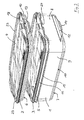
- FIGS. 1 to 3 show a stacking container system consisting of a tall container 1 and a flat container 2 and a first lid 3 and a second lid 4. Both the container 1, 2 and the lid 3, 4 are injection molded plastic.
- FIG. 1 All four parts of the stack container system shown here are stacked and locked together so that the entire stack can be handled as a single object.
- FIG. 2 the flat container 2 was released from its latching with the first lid 3 and removed from this, so that the stack has been divided into two separate, each with a lid 3 and 4 closed container.
- the flat container 2 stood the flat container 2 on the top 5 of the lid 3, so that its bottom 6 could not come into contact with the contents of the high container 1.
- FIG. 3 clarifies this again by the sectional view.
- the containers 1, 2 of the present embodiment have a substantially rectangular basic shape and comprise a bottom 6, 7, which - as is known - is corrugated to take over a drainage function, for example condensed water, and two end walls 8 and two side walls. 9 In the region of the bottom 6, 7 a retracted stacking edge 10 is provided, which can receive an upper edge 11 of a further container 1 and thus serves for the tight stacking of the two containers 1, 2. At the end walls 8 are downwardly bent, elastically deformable tabs 12, 13 formed on the container 1, 2, which overlap the stack edge 10 each down. The tabs 12 are equipped with an outwardly projecting handle portion 14, which ensures easier gripping of the tabs 12, 13 and at the same time forms an insertion bevel.
- a circumferential stiffening rib 15 serves at the end walls 8 at the same time as a latching element 16, which can be attacked by a snap hook 17 formed on the tab 12 or 13 inwardly, formed by a thickening to form a snap-in locking connection.
- a snap hook 17 formed on the tab 12 or 13 inwardly, formed by a thickening to form a snap-in locking connection.
- FIG. 3 easier to recognize.
- the snap fit between the snap hook 17 and the latch member 16 can be easily solved by deforming the tab 18, wherein the operator Lasche 18 then anyway in the hand and this serves as a handle for the removed part. The deformation of the tabs 12, 13, 18 is additionally facilitated by the handle part 14.
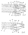
- FIG. 4 a detail enlargement FIG. 3 , The peculiarity of the two covers 3, 4, which are identical, clearly.
- a groove 19 for receiving the upper edge 11 of the container 2 expands in the region of the latching element 16 of the container 2 such that the groove bottom 20 is above the plane of the upper side 5 of the lid 4.
- the groove 19 has a U-shaped cross-section, the outer U-leg forms the tab 18 with handle portion 14 and snap hook 17.
- the snap hook 17 is oriented inwardly and engages, as shown, the latching element 16 of the container 2, so that the lid 4 is latched on the container 2.
- a recess 21 is arranged, which serves as a latching element 16 for the snap hook 17 of another container or another lid.
- FIG. 4 clearly recognizable as the tab 13 of the container 2 sits with its snap hook 17 in the recess 21 of the tab 18 of the lid 3 and the container 2 is locked to the lid 3.
- the inwardly oriented outside of the U-shaped groove 19 of the lid 3 forms a contact surface 22 for the bottom 6 of the container 2, so that its stacking edge 10 is in connection with the installation on the cover 3 without function.
- FIG. 2 shows most clearly, the covers 3, 4 a circumferential bead 23, in which the container 1, 2 can be adjusted.
- the edge bead 23 ensures orientation and alignment of the parts to be latched to one another and for additional support of the latched parts.
- the tabs 18 offer on their inside an additional insertion bevel or centering function.
- FIG. 5 finally shows, in a presentation like FIG. 4 , two configured lid 3, 4, which are directly locked together by means of their tabs 18.
- the snap hook 17 of the lid 4 engages as a holding element in the recess 21 of the lid 3 as a latching element, while the two U-shaped tabs 18 are stacked as it were inside one another. This allows an orderly storage of several, not in use lids 3, 4.
- FIGS. 1 to 5 shown parts of a stack container system only show an embodiment of the invention and the invention is not limited to the illustrated embodiments of the lid, container and the holding elements and locking elements.
Landscapes
- Engineering & Computer Science (AREA)
- Mechanical Engineering (AREA)
- Stackable Containers (AREA)
Description
- Die vorliegende Erfindung betrifft ein Stapelbehältersystem nach dem Oberbegriff des Anspruchs 1. Ein solches Stapelbehältersystem umfasst mindestens einen oben offenen Behälter und einen diesen nach oben abdeckenden Deckel, wobei der Behälter mit Halteelementen und Rastelementen versehen ist, die es ermöglichen, mehrere Behälter des Stapelbehältersystems aufeinanderzustapeln und lösbar untereinander zu verriegeln. Sowohl der Behälter als auch der Deckel bestehen bevorzugt aus Kunststoff.
- Insbesondere Kunststoffbehälter zur Aufbewahrung von Lebensmitteln im Kühlschrank oder im Gefrierschrank sowie Transportbehälter sollen sich in der Regel möglichst platzsparend unterbringen lassen. Dies lässt sich neben geeigneter Formung der Behälter unter anderem dadurch optimieren, dass die Behälter aufeinander stapelbar sind und ein Stapelbehältersystem bilden.
- Aus der
DE 202 09 983 U1 und derDE 203 06 780 U1 ist ein Stapelbehäktersystem der vorliegenden Art bekannt. Es handelt sich um ein System aus Kunststoffbehältern, die einen Boden, eine umlaufende Randfläche mit einem umlaufenden oberen Rand und einer im Bereich des Bodens in die Wandfläche eingebrachten, eingezogenen Stapelkante, sowie an mindestens zwei einander gegenüberliegenden Seiten der Wandfläche an dieser angebrachte Halteelemente und Rastelemente aufweisen. Nach diesem Stand der Technik läuft die Stapelkante im Bereich des Schalenbodens außen seitlich um und besteht aus einem Unterschnitt; im Rahmen der vorliegenden Erfindung kann die Stapelkante jedoch auch anders ausgebildet sein, beispielsweise durch eine unterbrochene oder umlaufende Rippe. - Im genannten Stand der Technik weisen die Behälter Halteelemente auf, die elastisch verformbar sind und mit den Rastelementen eines darunter angeordneten, mit seinem oberen Rand an der Stapelkante des Behälters sitzenden weiteren Behälters eine Rastverbindung herstellen können. Diese Rastverbindung kann durch Verformen der Halteelemente gelöst werden. Nach diesem Stand der Technik sind die elastisch verformbaren Halteelemente durch fest an der Schale angebrachte Laschen gebildet, die einen nach innen orientierten Schnapphaken aufweisen, der hinter das Rastelement des darunter angeordneten Behälters einrastet und hierdurch eine Schnapppassung herstellt. Um mehrere aufeinander gestapelte Behälter nach oben abzudecken, ist ein Deckel vorgesehen, der ebenso mit einer elastisch verformbaren Lasche versehen ist, die mittels eines nach innen orientierten Schnapphakens eine Schnapppassung mit den Rastelementen des obersten Behälters des Stapels herstellt. Auch die Laschen des Deckels sind mittels elastischer Verformung von den Rastelementen des Behälters lösbar, so dass der Deckel abgenommen werden kann.
- Ein weiteres bekanntes Stapelbehältersystem der vorliegenden Art ist in der
US 6,273,258 B1 offenbart. Dort wurde ein System von identisch ausgebildeten, stapelbaren Kunststoffbehältern vorgeschlagen, wobei die Behälter jeweils einen Unterschnitt am Stapelboden zur Ausbildung einer Stapelkante aufweisen. Oberhalb der Stapelkante ist an zwei gegenüberliegenden Außenseiten des Behälters jeweils eine Rastnase angeformt und oberhalb dieser Rastnase ist am oberen Behälterrand jeweils ein über ein Filmscharnier schwenkbar angeformtes Verbindungselement vorgesehen. Jedes Verbindungselement hintergreift in nach oben geschwenktem Zustand die entsprechende Rastnase eines oben aufgesetzten weiteren Behälters und stellt hierdurch einen lösbaren, einrastenden Formschluss her. Dieser Formschluss stellt sicher, dass die beiden so verbundenen Behälter dichtend aufeinandersitzen. - Den bekannten Stapelbehältersystemen nach dem Stand der Technik ist gemeinsam, dass Behälter aufeinander gestapelt und lösbar untereinander verrastet werden, wobei jeder Behälter, der auf einen anderen Behälter aufgesetzt wird, gleichzeitig diesen anderen Behälter nach oben abdeckt, also seinen "Deckel" bildet. Dies ermöglicht die optimal platzsparende Unterbringung von mehreren separaten Behältern, deren Inhalt voneinander getrennt und möglichst dicht eingeschlossen aufbewahrt oder transportiert werden soll. Durch die lösbare Verrastung der aufeinandergestapelten Behälter werden die Handhabung und der Transport der Mehrzahl von Behältern signifikant erleichtert, da sich der gesamte Behälterstapel wie ein einziger Behälter handhaben lässt.
- Auch wenn die genannten Stapelbehältersysteme nach dem Stand der Technik unter dem Gesichtspunkt der Volumeneinsparung optimiert sind, ist es unter anderen Gesichtspunkten manchmal nachteilig, dass der Boden eines aufgestapelten Behälters gleichzeitig als Deckel des darunter angeordneten Behälters dient. Insbesondere bei der Aufbewahrung und beim Transport von Lebensmitteln ist es so kaum zu verhindern, dass die Bodenfläche desjenigen Behälters, der einen anderen Behälter abdeckt, in Kontakt mit den darin transportierten oder aufbewahrten Lebensmitteln kommt oder aufgrund hoher, im Behälter herrschender Luftfeuchtigkeit mit Kondenswasser benetzt wird. Dies kann dann, wenn die Behälter voneinander gelöst und nebeneinander abgestellt werden, um an den Inhalt der Behälter gelangen zu können, problematisch sein. Denn Kondenswasser und/oder am Behälterboden anhaftende Lebensmittelbestandteile werden dann auf die Abstellfläche übertragen. Wenn ein Stapelbehältersystem nach dem Stand der Technik beispielsweise zur Aufbewahrung von Käse- oder Wurstaufschnitt im Kühlschrank aufeinandergestapelt verwendet und zum Anrichten einer Mahlzeit mit vereinzelten Behältern auf dem Esstisch platziert wird, kann dies dazu führen, dass der Esstisch mit Kondenswasser oder fetthaltigen Lebensmittelspuren (Weichkäse, Leberwurst und dergleichen) verschmutzt wird.
- Ausgehend von diesem Stand der Technik liegt der vorliegenden Erfindung die Aufgabe zugrunde, ein Stapelbehältersystem der eingangs genannten Art hinsichtlich der unkomplizierten Verwendbarkeit von vereinzelten Behältern zu verbessern und insbesondere eine Verschmutzung von Behälterböden zu vermeiden.
- Gelöst ist diese Aufgabe durch ein Stapelbehältersystem mit den Merkmalen des Anspruchs 1. Bevorzugte Ausgestaltungen und Weiterbildungen des erfindungsgemäßen Stapelbehältersystems sind in den Ansprüchen 2 bis 7 niedergelegt.
- Ein Stapelbehältersystem nach der vorliegenden Erfindung zeichnet sich demnach dadurch aus, dass mindestens ein Deckel vorgesehen ist, der sowohl mit Halteelementen als auch mit Rastelementen für lösbare Rastverbindungen nach unten und nach oben versehen ist. Es handelt sich hierbei also um einen Zwischendeckel, der sowohl auf einen Behälterrand aufgerastet werden kann, um diesen nach oben abzudecken, als auch mit einem auf seiner Oberseite stehenden Behälter verrastet werden kann. An dieser Stelle sei angemerkt, dass dies selbstverständlich nicht ausschließt, dass das erfindungsgemäße Stapelbehältersystem außerdem auch einen Deckel umfasst, der wie im Stand der Technik keine Rastverbindung nach oben herstellen kann.
- Mit einem solchen vorgesehenen Zwischendeckel ist es nun möglich, die einzelnen Behälter des Stapelbehältersystems so aufeinanderzustapeln und untereinander zu verrasten, dass zwischen mindestens zwei Behältern, vorzugsweise zwischen allen Behältern, jeweils ein ausgestalteter Deckel angeordnet ist. Da dieser Deckel Rastverbindungen nach oben und nach unten herstellen kann, ist der gesamte Behälterstapel dennoch stabil untereinander verrastet. Einzelne Behälter können durch Lösen der Rastverbindung vom Stapel abgehoben werden, wobei keine Gefahr besteht, dass der Behälterboden verschmutzt ist; denn dieser wurde durch den Zwischendeckel vor dem Inhalt des darunter angeordneten Behälters geschützt.
- Das erfindungsgemäße Stapelbehältersystem kann durch die jeweils vorhandenen identischen Halteelemente und Rastelemente an Behältern und Deckeln völlig frei gestapelt werden. Zwei Behälter können also wie im Stand der Technik direkt aufeinander gestapelt und miteinander verrastet werden, oder alternativ kann ein ausgestalteter Deckel dazwischen angeordnet und mit beiden beteiligten Behältern verrastet werden. Es ist auch möglich, mehrere ausgestaltete Deckel aufeinanderzusetzen und untereinander zu verrasten, so dass eine platzsparende und sichere Aufbewahrung derselben jederzeit gewährleistet ist.
- Vorteilhafterweise ist der ausgestaltete Deckel an seiner Oberseite mit mindestens einem Randwulst zum Einstellen eines Behälterbodens und/oder zum Einsetzen eines weiteren Deckels versehen. Dieser Randwulst kann umlaufend ausgebildet sein, er kann jedoch auch aus mehreren, voneinander separaten Teilen bestehen. Für den Randwulst kommt es lediglich darauf an, dass ein Behälterboden und/oder ein weiterer Deckel durch ihn geführt und auf der Deckeloberseite orientiert gehalten wird. Beispielsweise reicht es aus, an zwei Seiten des Deckels jeweils einen kleinen Wulst vorzusehen, um eine Zentrierwirkung für die Herstellung der Rastverbindung zu erzielen.
- Die Halteelemente des ausgestalteten Deckels sind vorzugsweise jeweils durch eine Erweiterung der umlaufenden Nut zur Aufnahme eines Behälterrands gebildet. Hierbei ist die Nut zur Bildung der Halteelemente vorzugsweise solcherart in der Tiefe erweitert, dass sich der Nutboden oberhalb der Ebene der Oberseite des Deckels befindet.
- Die Rastelemente, die gemäß der vorliegenden Erfindung ebenfalls am Deckel angebracht sind und mit Halteelementen eines weiteren Deckels oder eines Behälters verrastet werden können, sind besonders bevorzugt an einem die Halteelemente bildenden Teil des Deckels angeordnet. Dieser Teil erstreckt sich dann über eine Höhe, die es ermöglicht, die Rastelemente und die Halteelemente so weit voneinander zu beabstanden, wie die oberhalb und unterhalb des Deckels angeordneten Behälter durch das Einfügen eines Zwischendeckels weiter voneinander beabstandet sind, als bei einem direkten Aufeinanderstapeln der beiden Behälter.
- Bevorzugt weist der ausgestaltete Deckel zur Bildung der Halteelemente elastisch verformbare, angeformte Laschen auf, die im Querschnitt im wesentlichen U-förmig ausgebildet sowie am äußeren U-Schenkel mit einem nach innen orientierten Schnapphaken versehen sind. Insoweit stimmen diese Halteelemente dann mit den aus beispielsweise der
DE 203 06 780 U1 bekannten Halteelementen von Stapelbehältern überein. Außerdem sind die vorzugsweise als Halteelement vorgesehenen Laschen bevorzugt mit einem nach außen orientierten Rastelement versehen, in das die nach innen orientierten Schnapphaken von Halteelementen eines weiteren Deckels oder eines Behälters einrasten können. Dieses Rastelement kann als Vertiefung oder Öffnung zur Aufnahme eines Schnapphakens eines weiteren Deckels oder Behälters ausgebildet sein. Es ist im Rahmen der vorliegenden Erfindung jedoch möglich, das Rastelement auch anders, beispielsweise als Vorsprung auszubilden. - Ein Ausführungsbeispiel für ein erfindungsgemäß ausgestaltetes Stapelbehältersystem wird im Folgenden anhand der beigefügten Zeichnungen näher beschrieben und erläutert. Es zeigen:
- Figur 1
- eine perspektivische Ansicht eines erfindungsgemäß ausgestalteten Stapelbehältersystems;
- Figur 2
- eine perspektivische Ansicht des Stapelbehältersystems nach
Figur 1 , in teilweise auseinandergenommenem Zustand; - Figur 3
- das Stapelbehältersystem aus
Figur 1 , in einer teilgeschnittenen perspektivischen Darstellung; - Figur 4
- eine Detailvergrößerung aus
Figur 3 ; - Figur 5
- eine teilgeschnittene perspektivische Darstellung zweier ausgestalteter Zwischendeckel.
- Die
Figuren 1 bis 3 zeigen ein Stapelbehältersystem, bestehend aus einem hohen Behälter 1 und einem flachen Behälter 2 sowie einem ersten Deckel 3 und einem zweiten Deckel 4. Sowohl die Behälter 1, 2 als auch die Deckel 3, 4 sind Spritzgussteile aus Kunststoff. - In
Figur 1 sind alle vier Teile des hier dargestellten Stapelbehältersystems aufeinandergestapelt und untereinander verrastet, so dass der gesamte Stapel als einheitlicher Gegenstand gehandhabt werden kann. InFigur 2 wurde der flache Behälter 2 aus seiner Verrastung mit dem ersten Deckel 3 gelöst und von diesem abgenommen, so dass der Stapel in zwei separate, jeweils mit einem Deckel 3 bzw. 4 verschlossene Behälter geteilt worden ist. Wie man hier besonders gut erkennen kann, stand der flache Behälter 2 auf der Oberseite 5 des Deckels 3 auf, so dass sein Boden 6 nicht mit dem Inhalt des hohen Behälters 1 in Kontakt kommen konnte. -
Figur 3 verdeutlicht dies nochmals durch die Schnittdarstellung. - Die Behälter 1, 2 des vorliegenden Ausführungsbeispiels besitzen eine im wesentlichen rechteckige Grundform und umfassen einen Boden 6, 7, der - wie an sich bekannt - gewellt ist, um eine Drainagefunktion für beispielsweise Kondenswasser zu übernehmen, sowie zwei Stirnwände 8 und zwei Seitenwände 9. Im Bereich des Bodens 6, 7 ist jeweils eine eingezogene Stapelkante 10 vorgesehen, die einen oberen Rand 11 eines weiteren Behälters 1 aufnehmen kann und die somit zum dichten Aufeinanderstapeln der beiden Behälter 1, 2 dient. An den Stirnwänden 8 sind nach unten abgewinkelte, elastisch verformbare Laschen 12, 13 an die Behälter 1, 2 angeformt, die die Stapelkante 10 jeweils nach unten übergreifen. Die Laschen 12 sind mit einem nach außen auskragenden Griffteil 14 ausgestattet, das ein leichteres Ergreifen der Laschen 12, 13 sicherstellt und gleichzeitig eine Einführschräge bildet.
- Eine umlaufende Versteifungsrippe 15 dient an den Stirnwänden 8 gleichzeitig als Rastelement 16, das von einem an der Lasche 12 bzw. 13 nach innen orientierten, durch eine Verdickung gebildeten Schnapphaken 17 zur Bildung einer einschnappenden Rastverbindung untergriffen werden kann. Dies ist anhand
Figur 3 leichter zu erkennen. Wie hier außerdem leicht zu erkennen ist, kann die Schnapppassung zwischen dem Schnapphaken 17 und dem Rastelement 16 leicht durch Verformen der Lasche 18 gelöst werden, wobei der Bediener die Lasche 18 dann ohnehin in der Hand hat und diese als Griff für das abgenommene Teil dient. Das Verformen der Laschen 12, 13, 18 wird durch den Griffteil 14 zusätzlich erleichtert. - Anhand
Figur 4 , einer Detailvergrößerung ausFigur 3 , wird die Besonderheit der beiden Deckel 3, 4, die identisch ausgebildet sind, deutlich. Eine Nut 19 zur Aufnahme des oberen Randes 11 des Behälters 2 erweitert sich im Bereich des Rastelements 16 des Behälters 2 solcherart, dass sich der Nutboden 20 oberhalb der Ebene der Oberseite 5 des Deckels 4 befindet. Die Nut 19 weist einen U-förmigen Querschnitt auf, dessen äußerer U-Schenkel die Lasche 18 mit Griffteil 14 und Schnapphaken 17 bildet. Der Schnapphaken 17 ist nach innen orientiert und untergreift, wie gezeigt, das Rastelement 16 des Behälters 2, so dass der Deckel 4 auf dem Behälter 2 verrastet ist. - Auf der Außenseite der Lasche 18 ist eine Vertiefung 21 angeordnet, die als Rastelement 16 für den Schnapphaken 17 eines weiteren Behälters oder eines weiteren Deckels dient. Folgerichtig ist in
Figur 4 gut erkennbar, wie die Lasche 13 des Behälters 2 mit ihrem Schnapphaken 17 in der Vertiefung 21 der Lasche 18 des Deckels 3 sitzt und den Behälter 2 mit dem Deckel 3 verrastet. Gleichzeitig bildet die nach innen orientierte Außenseite der U-förmigen Nut 19 des Deckels 3 eine Anlagefläche 22 für den Boden 6 des Behälters 2, so dass seine Stapelkante 10 im Zusammenhang mit dem Aufstellen auf den Deckel 3 ohne Funktion ist. - Wie wiederum
Figur 2 am deutlichsten darstellt, weisen die Deckel 3, 4 einen umlaufenden Randwulst 23 auf, in den die Behälter 1, 2 eingestellt werden können. Der Randwulst 23 sorgt für eine Orientierung und Ausrichtung der zu verrastenden Teile zueinander sowie für zusätzlichen Halt der miteinander verrasteten Teile. Die Laschen 18 bieten auf ihrer Innenseite eine zusätzliche Einführschräge bzw. Zentrierfunktion. - Wie ebenfalls anhand der
Figuren 1 und2 erkennbar, ist in die Laschen 18 der Deckel 3, 4 jeweils eine Kerbe 24 eingebracht, so dass ein Benutzer die Laschen 12, 13 der Behälter 1, 2 einerseits und die Laschen 18 der Deckel 3, 4 andererseits "blind" voneinander unterscheiden kann. Dies erleichtert das Separieren eines Behälterstapels, wie es inFigur 2 dargestellt ist. - Für weitere Details und Funktionen der Behälter 1, 2 des vorliegenden Ausführungsbeispiels wird hiermit ausdrücklich auf die
DE 202 09 983 und dieDE 203 06 780 der Anmelderin Bezug genommen. -
Figur 5 zeigt schließlich, in einer Darstellung wieFigur 4 , zwei ausgestaltete Deckel 3, 4, die direkt mittels ihrer Laschen 18 untereinander verrastet sind. Hierzu greift der Schnapphaken 17 des Deckels 4 als Halteelement in die Vertiefung 21 des Deckels 3 als Rastelement ein, während die beiden U-förmig ausgebildeten Laschen 18 gleichsam ineinander gestapelt sind. Dies ermöglicht eine geordnete Aufbewahrung von mehreren, nicht in Benutzung befindlichen Deckeln 3, 4. - Abschließend sei bemerkt, dass die in den
Figuren 1 bis 5 dargestellten Teile eines Stapelbehältersystems nur ein Ausführungsbeispiel der Erfindung zeigen und die Erfindung nicht auf die dargestellten Ausgestaltungen der Deckel, Behälter sowie der Halteelemente und Rastelemente beschränkt ist.
Claims (7)
- Stapelbehältersystem, umfassend mindestens einen oben offenen Behälter (1, 2) und einen diesen nach oben abdeckenden Deckel (3, 4) mit einer Unterseite und einer Oberseite (5),
wobei der Behälter (1, 2) einen Boden (6, 7), eine umlaufende Wandfläche (8, 9) mit einem umlaufenden oberen Rand (11) und einer im Bereich des Bodens (6, 7) in die Wandfläche (8, 9) eingebrachten, eingezogenen Stapelkante (10), sowie an mindestens zwei einander gegenüber liegenden Seiten (8) der Wandfläche (8, 9) an dieser angebrachte Halteelemente (12, 13) und Rastelemente (16) umfasst,
wobei die Halteelemente (12, 13) schwenkbar und/oder elastisch verformbar sind und mit den Rastelementen (16) eines darunter angeordneten, mit seinem oberen Rand (11) an der Stapelkante (10) des Behälters (2) sitzenden weiteren Behälters (1) eine durch Verschwenken und/oder Verformen lösbare Rastverbindung herstellen können, oder mit den Rastelementen (16) eines darüber angeordneten weiteren Behälters, dessen Stapelkante am oberen Rand (11) der Wandfläche (8, 9) des Behälters (2) sitzt, eine durch Verschwenken und/oder Verformen lösbare Rastverbindung herstellen können,
und wobei der Deckel (3, 4) an seiner Unterseite eine im wesentlichen umlaufende Nut (19) zur Aufnahme des oberen Randes (11) des Behälters (3, 4), sowie Halteelemente (18) oder Rastelemente (21) zum Herstellen einer durch Verschwenken und/oder Verformen der Halteelemente (18) lösbaren Rastverbindung mit dem Behälter (1, 2) aufweist,
dadurch gekennzeichnet,
dass der Deckel (3, 4) sowohl mit Halteelementen (18) als auch mit Rastelementen (21) für lösbare Rastverbindungen nach unten und nach oben versehen ist. - Stapelbehältersystem nach Anspruch 1,
dadurch gekennzeichnet,
dass der Deckel (3) an seiner Oberseite (5) mindestens einen Randwulst (23) zum Einstellen eines Behälterbodens (6, 7) und/oder zum Einsetzen eines weiteren Deckels (4) aufweist. - Stapelbehältersystem nach einem der Ansprüche 1 oder 2,
dadurch gekennzeichnet,
dass die Halteelemente (18) des Deckels (3, 4) jeweils durch eine Erweiterung der Nut (19) gebildet sind. - Stapelbehältersystem nach den Ansprüchen 2 und 3,
dadurch gekennzeichnet,
dass die Nut (19) zur Bildung der Halteelemente (18) jeweils solcherart in der Tiefe erweitert ist, dass sich der Nutboden (20) oberhalb der Ebene der Oberseite (5) des Deckels (3, 4) befindet. - Stapelbehältersystem nach mindestens einem der Ansprüche 1 bis 4,
dadurch gekennzeichnet,
dass die Rastelemente (21) des Deckels (3, 4) an einem die Halteelemente (18) bildenden Teil des Deckels (3, 4) angeordnet sind. - Stapelbehältersystem nach mindestens einem der Ansprüche 1 bis 5,
dadurch gekennzeichnet,
dass der Deckel (3, 4) zur Bildung der Halteelemente elastisch verformbare, angeformte Laschen (18) aufweist, die im Querschnitt im wesentlichen U-förmig ausgebildet sowie am äußeren U-Schenkel mit einem nach innen orientierten Schnapphaken (17) und einem nach außen orientierten Rastelement (21) versehen sind. - Stapelbehältersystem nach Anspruch 6,
dadurch gekennzeichnet,
dass das Rastelement als Vertiefung (21) oder Öffnung zur Aufnahme eines Schnapphakens, (17) eines weiteren Deckels (4) oder Behälters (1, 2) ausgebildet ist.
Priority Applications (3)
| Application Number | Priority Date | Filing Date | Title |
|---|---|---|---|
| ES12159064.0T ES2487796T3 (es) | 2012-03-12 | 2012-03-12 | Sistema de recipientes apilables |
| EP12159064.0A EP2639175B1 (de) | 2012-03-12 | 2012-03-12 | Stapelbehältersystem |
| PL12159064T PL2639175T3 (pl) | 2012-03-12 | 2012-03-12 | System pojemników układanych w stos |
Applications Claiming Priority (1)
| Application Number | Priority Date | Filing Date | Title |
|---|---|---|---|
| EP12159064.0A EP2639175B1 (de) | 2012-03-12 | 2012-03-12 | Stapelbehältersystem |
Publications (2)
| Publication Number | Publication Date |
|---|---|
| EP2639175A1 EP2639175A1 (de) | 2013-09-18 |
| EP2639175B1 true EP2639175B1 (de) | 2014-06-04 |
Family
ID=45930573
Family Applications (1)
| Application Number | Title | Priority Date | Filing Date |
|---|---|---|---|
| EP12159064.0A Active EP2639175B1 (de) | 2012-03-12 | 2012-03-12 | Stapelbehältersystem |
Country Status (3)
| Country | Link |
|---|---|
| EP (1) | EP2639175B1 (de) |
| ES (1) | ES2487796T3 (de) |
| PL (1) | PL2639175T3 (de) |
Cited By (1)
| Publication number | Priority date | Publication date | Assignee | Title |
|---|---|---|---|---|
| DE202015103431U1 (de) | 2015-06-30 | 2015-07-09 | Rotho Advanced Solutions Ag | Stapelbarer Lagerbehälter |
Family Cites Families (8)
| Publication number | Priority date | Publication date | Assignee | Title |
|---|---|---|---|---|
| DE3904053A1 (de) * | 1989-02-10 | 1990-08-23 | Dillinger Juergen Dipl Finanzw | Baukastensystem |
| US6273258B1 (en) | 2000-02-01 | 2001-08-14 | Snips S.R.L. | System of identical modular containers which can be piled up on top of one another, in particular for foodstuffs |
| DE20209983U1 (de) | 2002-06-27 | 2002-09-05 | Rotho Kunststoff AG, Würenlingen | Stapelbarer Kunststoffbehälter |
| US7510096B2 (en) * | 2003-04-09 | 2009-03-31 | Korea Alphaline Co., Ltd. | Multi-layered container with intermediate lid |
| NZ571242A (en) * | 2006-02-09 | 2010-06-25 | Rubbermaid Inc | Storage container and container system |
| KR20090096058A (ko) * | 2008-03-07 | 2009-09-10 | 주식회사 락앤락 | 적층형 보관용기 |
| US8376179B2 (en) * | 2010-06-28 | 2013-02-19 | Mead Johnson Nutrition Company | Container and closure |
| US8813960B2 (en) * | 2010-08-02 | 2014-08-26 | Becklin Holdings, Inc. | Latch system for containers |
-
2012
- 2012-03-12 EP EP12159064.0A patent/EP2639175B1/de active Active
- 2012-03-12 PL PL12159064T patent/PL2639175T3/pl unknown
- 2012-03-12 ES ES12159064.0T patent/ES2487796T3/es active Active
Cited By (2)
| Publication number | Priority date | Publication date | Assignee | Title |
|---|---|---|---|---|
| DE202015103431U1 (de) | 2015-06-30 | 2015-07-09 | Rotho Advanced Solutions Ag | Stapelbarer Lagerbehälter |
| WO2017001083A1 (de) | 2015-06-30 | 2017-01-05 | Rotho Advanced Solutions Ag | Stapelbarer lagerbehälter |
Also Published As
| Publication number | Publication date |
|---|---|
| ES2487796T3 (es) | 2014-08-25 |
| EP2639175A1 (de) | 2013-09-18 |
| PL2639175T3 (pl) | 2014-09-30 |
Similar Documents
| Publication | Publication Date | Title |
|---|---|---|
| EP3325221B1 (de) | Aufbewahrungsbehälter | |
| EP2540638B1 (de) | Schachtelbare Verpackungsbehältnisse | |
| EP3576518B1 (de) | Tray zum kultivieren von pflanzen und system umfassend tray und pflanztopf | |
| EP2551210B1 (de) | Stapelanordnung aus unterschiedlichen Behältern | |
| EP3759030B1 (de) | Transportbehälter mit variabler fachunterteilung | |
| EP3162197B1 (de) | Faltbare transportbox | |
| EP3285973B1 (de) | Aufbewahrungsbehälter | |
| EP3640155B1 (de) | Vakuumisolationstransportbehälter für den temperaturgeführten transport | |
| AT17987U1 (de) | Mehrweg-Servier- und/oder –Transportverpackung für Nahrungsmittel | |
| WO2017001083A1 (de) | Stapelbarer lagerbehälter | |
| EP2639175A1 (de) | Stapelbehältersystem | |
| DE102015121865B4 (de) | Transportbox | |
| DE202014103156U1 (de) | Pflanzentray | |
| EP2138414B1 (de) | Behälter | |
| DE20306780U1 (de) | Stapelbarer Kunststoffbehälter | |
| EP2735520B1 (de) | Schließelemente für das Griffloch eines Behälters | |
| DE102012216739B4 (de) | Kunststoffbehälter mit Deckel und Tragemerkmal | |
| EP3572344A1 (de) | Behälter mit deckel | |
| EP1660827A1 (de) | Ablagevorrichtung für ein kältegerät | |
| EP2540639B1 (de) | Verpackung für Lebensmittel, insbesondere für Frischkäseprodukte, Pasteten, Brotaufstriche und dgl. | |
| DE602005002109T2 (de) | Transportbehälter für Pflanzenstecklinge | |
| DE102013010382B3 (de) | Transportbehälter für frische Lebensmittel, insbesondere Fisch | |
| DE202011102578U1 (de) | Verpackung für Lebensmittel, insbesondere für Frischkäseprodukte, Pasteten, Brotaufstriche und dgl. | |
| DE202011102579U1 (de) | Verpackung für Lebensmittel, insbesondere für Frischkäseprodukte, Pasteten, Brotaufstriche und dgl. | |
| CH477329A (de) | Flaschentransportkasten aus Kunststoff |
Legal Events
| Date | Code | Title | Description |
|---|---|---|---|
| PUAI | Public reference made under article 153(3) epc to a published international application that has entered the european phase |
Free format text: ORIGINAL CODE: 0009012 |
|
| AK | Designated contracting states |
Kind code of ref document: A1 Designated state(s): AL AT BE BG CH CY CZ DE DK EE ES FI FR GB GR HR HU IE IS IT LI LT LU LV MC MK MT NL NO PL PT RO RS SE SI SK SM TR |
|
| AX | Request for extension of the european patent |
Extension state: BA ME |
|
| 17P | Request for examination filed |
Effective date: 20130920 |
|
| RBV | Designated contracting states (corrected) |
Designated state(s): AL AT BE BG CH CY CZ DE DK EE ES FI FR GB GR HR HU IE IS IT LI LT LU LV MC MK MT NL NO PL PT RO RS SE SI SK SM TR |
|
| RIC1 | Information provided on ipc code assigned before grant |
Ipc: B65D 43/02 20060101ALI20131128BHEP Ipc: B65D 21/02 20060101AFI20131128BHEP |
|
| GRAP | Despatch of communication of intention to grant a patent |
Free format text: ORIGINAL CODE: EPIDOSNIGR1 |
|
| INTG | Intention to grant announced |
Effective date: 20140124 |
|
| GRAS | Grant fee paid |
Free format text: ORIGINAL CODE: EPIDOSNIGR3 |
|
| GRAA | (expected) grant |
Free format text: ORIGINAL CODE: 0009210 |
|
| AK | Designated contracting states |
Kind code of ref document: B1 Designated state(s): AL AT BE BG CH CY CZ DE DK EE ES FI FR GB GR HR HU IE IS IT LI LT LU LV MC MK MT NL NO PL PT RO RS SE SI SK SM TR |
|
| REG | Reference to a national code |
Ref country code: GB Ref legal event code: FG4D Free format text: NOT ENGLISH |
|
| REG | Reference to a national code |
Ref country code: CH Ref legal event code: EP |
|
| REG | Reference to a national code |
Ref country code: AT Ref legal event code: REF Ref document number: 670945 Country of ref document: AT Kind code of ref document: T Effective date: 20140615 |
|
| REG | Reference to a national code |
Ref country code: IE Ref legal event code: FG4D Free format text: LANGUAGE OF EP DOCUMENT: GERMAN |
|
| REG | Reference to a national code |
Ref country code: CH Ref legal event code: NV Representative=s name: RENTSCH PARTNER AG, CH |
|
| REG | Reference to a national code |
Ref country code: DE Ref legal event code: R096 Ref document number: 502012000802 Country of ref document: DE Effective date: 20140717 |
|
| REG | Reference to a national code |
Ref country code: ES Ref legal event code: FG2A Ref document number: 2487796 Country of ref document: ES Kind code of ref document: T3 Effective date: 20140825 |
|
| REG | Reference to a national code |
Ref country code: PL Ref legal event code: T3 |
|
| REG | Reference to a national code |
Ref country code: NL Ref legal event code: VDEP Effective date: 20140604 |
|
| PG25 | Lapsed in a contracting state [announced via postgrant information from national office to epo] |
Ref country code: GR Free format text: LAPSE BECAUSE OF FAILURE TO SUBMIT A TRANSLATION OF THE DESCRIPTION OR TO PAY THE FEE WITHIN THE PRESCRIBED TIME-LIMIT Effective date: 20140905 Ref country code: LT Free format text: LAPSE BECAUSE OF FAILURE TO SUBMIT A TRANSLATION OF THE DESCRIPTION OR TO PAY THE FEE WITHIN THE PRESCRIBED TIME-LIMIT Effective date: 20140604 Ref country code: CY Free format text: LAPSE BECAUSE OF FAILURE TO SUBMIT A TRANSLATION OF THE DESCRIPTION OR TO PAY THE FEE WITHIN THE PRESCRIBED TIME-LIMIT Effective date: 20140604 Ref country code: NO Free format text: LAPSE BECAUSE OF FAILURE TO SUBMIT A TRANSLATION OF THE DESCRIPTION OR TO PAY THE FEE WITHIN THE PRESCRIBED TIME-LIMIT Effective date: 20140904 Ref country code: FI Free format text: LAPSE BECAUSE OF FAILURE TO SUBMIT A TRANSLATION OF THE DESCRIPTION OR TO PAY THE FEE WITHIN THE PRESCRIBED TIME-LIMIT Effective date: 20140604 |
|
| REG | Reference to a national code |
Ref country code: LT Ref legal event code: MG4D |
|
| PG25 | Lapsed in a contracting state [announced via postgrant information from national office to epo] |
Ref country code: SE Free format text: LAPSE BECAUSE OF FAILURE TO SUBMIT A TRANSLATION OF THE DESCRIPTION OR TO PAY THE FEE WITHIN THE PRESCRIBED TIME-LIMIT Effective date: 20140604 Ref country code: HR Free format text: LAPSE BECAUSE OF FAILURE TO SUBMIT A TRANSLATION OF THE DESCRIPTION OR TO PAY THE FEE WITHIN THE PRESCRIBED TIME-LIMIT Effective date: 20140604 Ref country code: LV Free format text: LAPSE BECAUSE OF FAILURE TO SUBMIT A TRANSLATION OF THE DESCRIPTION OR TO PAY THE FEE WITHIN THE PRESCRIBED TIME-LIMIT Effective date: 20140604 Ref country code: RS Free format text: LAPSE BECAUSE OF FAILURE TO SUBMIT A TRANSLATION OF THE DESCRIPTION OR TO PAY THE FEE WITHIN THE PRESCRIBED TIME-LIMIT Effective date: 20140604 |
|
| PG25 | Lapsed in a contracting state [announced via postgrant information from national office to epo] |
Ref country code: EE Free format text: LAPSE BECAUSE OF FAILURE TO SUBMIT A TRANSLATION OF THE DESCRIPTION OR TO PAY THE FEE WITHIN THE PRESCRIBED TIME-LIMIT Effective date: 20140604 Ref country code: CZ Free format text: LAPSE BECAUSE OF FAILURE TO SUBMIT A TRANSLATION OF THE DESCRIPTION OR TO PAY THE FEE WITHIN THE PRESCRIBED TIME-LIMIT Effective date: 20140604 Ref country code: PT Free format text: LAPSE BECAUSE OF FAILURE TO SUBMIT A TRANSLATION OF THE DESCRIPTION OR TO PAY THE FEE WITHIN THE PRESCRIBED TIME-LIMIT Effective date: 20141006 Ref country code: RO Free format text: LAPSE BECAUSE OF FAILURE TO SUBMIT A TRANSLATION OF THE DESCRIPTION OR TO PAY THE FEE WITHIN THE PRESCRIBED TIME-LIMIT Effective date: 20140604 Ref country code: SK Free format text: LAPSE BECAUSE OF FAILURE TO SUBMIT A TRANSLATION OF THE DESCRIPTION OR TO PAY THE FEE WITHIN THE PRESCRIBED TIME-LIMIT Effective date: 20140604 |
|
| PG25 | Lapsed in a contracting state [announced via postgrant information from national office to epo] |
Ref country code: IS Free format text: LAPSE BECAUSE OF FAILURE TO SUBMIT A TRANSLATION OF THE DESCRIPTION OR TO PAY THE FEE WITHIN THE PRESCRIBED TIME-LIMIT Effective date: 20141004 Ref country code: NL Free format text: LAPSE BECAUSE OF FAILURE TO SUBMIT A TRANSLATION OF THE DESCRIPTION OR TO PAY THE FEE WITHIN THE PRESCRIBED TIME-LIMIT Effective date: 20140604 |
|
| REG | Reference to a national code |
Ref country code: DE Ref legal event code: R097 Ref document number: 502012000802 Country of ref document: DE |
|
| PLBE | No opposition filed within time limit |
Free format text: ORIGINAL CODE: 0009261 |
|
| STAA | Information on the status of an ep patent application or granted ep patent |
Free format text: STATUS: NO OPPOSITION FILED WITHIN TIME LIMIT |
|
| PG25 | Lapsed in a contracting state [announced via postgrant information from national office to epo] |
Ref country code: DK Free format text: LAPSE BECAUSE OF FAILURE TO SUBMIT A TRANSLATION OF THE DESCRIPTION OR TO PAY THE FEE WITHIN THE PRESCRIBED TIME-LIMIT Effective date: 20140604 |
|
| PGFP | Annual fee paid to national office [announced via postgrant information from national office to epo] |
Ref country code: ES Payment date: 20150325 Year of fee payment: 4 Ref country code: IT Payment date: 20150331 Year of fee payment: 4 |
|
| 26N | No opposition filed |
Effective date: 20150305 |
|
| REG | Reference to a national code |
Ref country code: DE Ref legal event code: R097 Ref document number: 502012000802 Country of ref document: DE Effective date: 20150305 |
|
| PG25 | Lapsed in a contracting state [announced via postgrant information from national office to epo] |
Ref country code: SI Free format text: LAPSE BECAUSE OF FAILURE TO SUBMIT A TRANSLATION OF THE DESCRIPTION OR TO PAY THE FEE WITHIN THE PRESCRIBED TIME-LIMIT Effective date: 20140604 |
|
| PG25 | Lapsed in a contracting state [announced via postgrant information from national office to epo] |
Ref country code: MC Free format text: LAPSE BECAUSE OF FAILURE TO SUBMIT A TRANSLATION OF THE DESCRIPTION OR TO PAY THE FEE WITHIN THE PRESCRIBED TIME-LIMIT Effective date: 20140604 Ref country code: LU Free format text: LAPSE BECAUSE OF FAILURE TO SUBMIT A TRANSLATION OF THE DESCRIPTION OR TO PAY THE FEE WITHIN THE PRESCRIBED TIME-LIMIT Effective date: 20150312 |
|
| REG | Reference to a national code |
Ref country code: IE Ref legal event code: MM4A |
|
| PG25 | Lapsed in a contracting state [announced via postgrant information from national office to epo] |
Ref country code: IE Free format text: LAPSE BECAUSE OF NON-PAYMENT OF DUE FEES Effective date: 20150312 |
|
| REG | Reference to a national code |
Ref country code: FR Ref legal event code: PLFP Year of fee payment: 5 |
|
| GBPC | Gb: european patent ceased through non-payment of renewal fee |
Effective date: 20160312 |
|
| PG25 | Lapsed in a contracting state [announced via postgrant information from national office to epo] |
Ref country code: MT Free format text: LAPSE BECAUSE OF FAILURE TO SUBMIT A TRANSLATION OF THE DESCRIPTION OR TO PAY THE FEE WITHIN THE PRESCRIBED TIME-LIMIT Effective date: 20140604 |
|
| PG25 | Lapsed in a contracting state [announced via postgrant information from national office to epo] |
Ref country code: GB Free format text: LAPSE BECAUSE OF NON-PAYMENT OF DUE FEES Effective date: 20160312 |
|
| PG25 | Lapsed in a contracting state [announced via postgrant information from national office to epo] |
Ref country code: IT Free format text: LAPSE BECAUSE OF NON-PAYMENT OF DUE FEES Effective date: 20160312 |
|
| REG | Reference to a national code |
Ref country code: FR Ref legal event code: PLFP Year of fee payment: 6 |
|
| REG | Reference to a national code |
Ref country code: ES Ref legal event code: FD2A Effective date: 20170427 |
|
| PG25 | Lapsed in a contracting state [announced via postgrant information from national office to epo] |
Ref country code: SM Free format text: LAPSE BECAUSE OF FAILURE TO SUBMIT A TRANSLATION OF THE DESCRIPTION OR TO PAY THE FEE WITHIN THE PRESCRIBED TIME-LIMIT Effective date: 20140604 Ref country code: HU Free format text: LAPSE BECAUSE OF FAILURE TO SUBMIT A TRANSLATION OF THE DESCRIPTION OR TO PAY THE FEE WITHIN THE PRESCRIBED TIME-LIMIT; INVALID AB INITIO Effective date: 20120312 Ref country code: BG Free format text: LAPSE BECAUSE OF FAILURE TO SUBMIT A TRANSLATION OF THE DESCRIPTION OR TO PAY THE FEE WITHIN THE PRESCRIBED TIME-LIMIT Effective date: 20140604 |
|
| REG | Reference to a national code |
Ref country code: CH Ref legal event code: NV Representative=s name: CMSRK RENTSCH KAELIN AG, CH |
|
| PG25 | Lapsed in a contracting state [announced via postgrant information from national office to epo] |
Ref country code: BE Free format text: LAPSE BECAUSE OF NON-PAYMENT OF DUE FEES Effective date: 20150331 |
|
| PG25 | Lapsed in a contracting state [announced via postgrant information from national office to epo] |
Ref country code: TR Free format text: LAPSE BECAUSE OF FAILURE TO SUBMIT A TRANSLATION OF THE DESCRIPTION OR TO PAY THE FEE WITHIN THE PRESCRIBED TIME-LIMIT Effective date: 20140604 Ref country code: ES Free format text: LAPSE BECAUSE OF NON-PAYMENT OF DUE FEES Effective date: 20160313 |
|
| REG | Reference to a national code |
Ref country code: CH Ref legal event code: PFA Owner name: ROTHO KUNSTSTOFF AG, CH Free format text: FORMER OWNER: ROTHO KUNSTSTOFF AG, CH |
|
| REG | Reference to a national code |
Ref country code: CH Ref legal event code: PCAR Free format text: NEW ADDRESS: HIRSCHENGRABEN 1, 8001 ZUERICH (CH) |
|
| REG | Reference to a national code |
Ref country code: FR Ref legal event code: PLFP Year of fee payment: 7 |
|
| PG25 | Lapsed in a contracting state [announced via postgrant information from national office to epo] |
Ref country code: MK Free format text: LAPSE BECAUSE OF FAILURE TO SUBMIT A TRANSLATION OF THE DESCRIPTION OR TO PAY THE FEE WITHIN THE PRESCRIBED TIME-LIMIT Effective date: 20140604 |
|
| PG25 | Lapsed in a contracting state [announced via postgrant information from national office to epo] |
Ref country code: AL Free format text: LAPSE BECAUSE OF FAILURE TO SUBMIT A TRANSLATION OF THE DESCRIPTION OR TO PAY THE FEE WITHIN THE PRESCRIBED TIME-LIMIT Effective date: 20140604 |
|
| PGFP | Annual fee paid to national office [announced via postgrant information from national office to epo] |
Ref country code: FR Payment date: 20210319 Year of fee payment: 10 |
|
| PGFP | Annual fee paid to national office [announced via postgrant information from national office to epo] |
Ref country code: AT Payment date: 20210318 Year of fee payment: 10 |
|
| PGFP | Annual fee paid to national office [announced via postgrant information from national office to epo] |
Ref country code: PL Payment date: 20220303 Year of fee payment: 11 |
|
| REG | Reference to a national code |
Ref country code: AT Ref legal event code: MM01 Ref document number: 670945 Country of ref document: AT Kind code of ref document: T Effective date: 20220312 |
|
| PG25 | Lapsed in a contracting state [announced via postgrant information from national office to epo] |
Ref country code: FR Free format text: LAPSE BECAUSE OF NON-PAYMENT OF DUE FEES Effective date: 20220331 Ref country code: AT Free format text: LAPSE BECAUSE OF NON-PAYMENT OF DUE FEES Effective date: 20220312 |
|
| P01 | Opt-out of the competence of the unified patent court (upc) registered |
Effective date: 20230509 |
|
| PGFP | Annual fee paid to national office [announced via postgrant information from national office to epo] |
Ref country code: CH Payment date: 20230402 Year of fee payment: 12 |
|
| PG25 | Lapsed in a contracting state [announced via postgrant information from national office to epo] |
Ref country code: PL Free format text: LAPSE BECAUSE OF NON-PAYMENT OF DUE FEES Effective date: 20230312 |
|
| PG25 | Lapsed in a contracting state [announced via postgrant information from national office to epo] |
Ref country code: PL Free format text: LAPSE BECAUSE OF NON-PAYMENT OF DUE FEES Effective date: 20230312 |
|
| REG | Reference to a national code |
Ref country code: CH Ref legal event code: PL |
|
| PG25 | Lapsed in a contracting state [announced via postgrant information from national office to epo] |
Ref country code: CH Free format text: LAPSE BECAUSE OF NON-PAYMENT OF DUE FEES Effective date: 20240331 |
|
| PGFP | Annual fee paid to national office [announced via postgrant information from national office to epo] |
Ref country code: DE Payment date: 20260120 Year of fee payment: 15 |