EP2636213B1 - Dynamic tapping force feedback for mobile devices - Google Patents
Dynamic tapping force feedback for mobile devices Download PDFInfo
- Publication number
- EP2636213B1 EP2636213B1 EP11793527.0A EP11793527A EP2636213B1 EP 2636213 B1 EP2636213 B1 EP 2636213B1 EP 11793527 A EP11793527 A EP 11793527A EP 2636213 B1 EP2636213 B1 EP 2636213B1
- Authority
- EP
- European Patent Office
- Prior art keywords
- force feedback
- dynamic force
- current
- message
- type
- Prior art date
- Legal status (The legal status is an assumption and is not a legal conclusion. Google has not performed a legal analysis and makes no representation as to the accuracy of the status listed.)
- Not-in-force
Links
Images


Classifications
-
- G—PHYSICS
- G06—COMPUTING OR CALCULATING; COUNTING
- G06F—ELECTRIC DIGITAL DATA PROCESSING
- G06F3/00—Input arrangements for transferring data to be processed into a form capable of being handled by the computer; Output arrangements for transferring data from processing unit to output unit, e.g. interface arrangements
- G06F3/01—Input arrangements or combined input and output arrangements for interaction between user and computer
- G06F3/016—Input arrangements with force or tactile feedback as computer generated output to the user
-
- G—PHYSICS
- G06—COMPUTING OR CALCULATING; COUNTING
- G06F—ELECTRIC DIGITAL DATA PROCESSING
- G06F1/00—Details not covered by groups G06F3/00 - G06F13/00 and G06F21/00
- G06F1/16—Constructional details or arrangements
- G06F1/1613—Constructional details or arrangements for portable computers
- G06F1/1633—Constructional details or arrangements of portable computers not specific to the type of enclosures covered by groups G06F1/1615 - G06F1/1626
- G06F1/1684—Constructional details or arrangements related to integrated I/O peripherals not covered by groups G06F1/1635 - G06F1/1675
-
- G—PHYSICS
- G08—SIGNALLING
- G08B—SIGNALLING SYSTEMS, e.g. PERSONAL CALLING SYSTEMS; ORDER TELEGRAPHS; ALARM SYSTEMS
- G08B6/00—Tactile signalling systems, e.g. tactile personal calling systems
-
- H—ELECTRICITY
- H04—ELECTRIC COMMUNICATION TECHNIQUE
- H04M—TELEPHONIC COMMUNICATION
- H04M1/00—Substation equipment, e.g. for use by subscribers
- H04M1/72—Mobile telephones; Cordless telephones, i.e. devices for establishing wireless links to base stations without route selection
- H04M1/724—User interfaces specially adapted for cordless or mobile telephones
- H04M1/72403—User interfaces specially adapted for cordless or mobile telephones with means for local support of applications that increase the functionality
- H04M1/7243—User interfaces specially adapted for cordless or mobile telephones with means for local support of applications that increase the functionality with interactive means for internal management of messages
-
- H—ELECTRICITY
- H04—ELECTRIC COMMUNICATION TECHNIQUE
- H04M—TELEPHONIC COMMUNICATION
- H04M19/00—Current supply arrangements for telephone systems
- H04M19/02—Current supply arrangements for telephone systems providing ringing current or supervisory tones, e.g. dialling tone or busy tone
- H04M19/04—Current supply arrangements for telephone systems providing ringing current or supervisory tones, e.g. dialling tone or busy tone the ringing-current being generated at the substations
- H04M19/047—Vibrating means for incoming calls
Definitions
- the disclosure relates to motion induction, and more particularly, to motion induction in wireless devices.
- Mobile devices such as audio players and cellular phones, often include vibration devices for providing the user feedback about conditions on the wireless device.
- a cellular phone may vibrate when an incoming call is ringing.
- Vibration motors are conventionally rotating eccentric mass motors in which a mass is rotated about a fixed point. Vibration motors typically draw large current during operation, which is undesirable for battery powered mobile devices. Additionally, vibration motors have haptic bandwidth.
- Mobile devices may have several kinds of feedback to provide the user such as, for example, low battery and incoming call. The limited bandwidth of vibration motors inhibits mobile devices from providing different alerts to the user through the vibration motor.
- European patent application published under number 2 244 169 describes a method for providing feedback at a mobile terminal.
- US patent application published under number 2010/273469 describes a warning system incorporable into a portable telephone providing a vibration alert for the presence of a radio frequency communication.
- a user is alerted to an RF communication when he presents the warning system, mainly by hand, to a contactless terminal or when a reader is brought close to him without his knowledge.
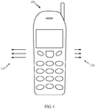
- FIGURE 1 illustrates an exemplary embodiment of a handheld device 100 incorporating force induction techniques of the present disclosure.
- the handheld device 100 is shown as a mobile phone.
- a handheld device of the present disclosure need not be a mobile phone, and may generally be any type of handheld device, e.g., a personal digital assistant (PDA), a personal navigation device, smart phone, etc.
- PDA personal digital assistant
- Such alternative exemplary embodiments are contemplated to be within the scope of the present disclosure.
- the handheld device 100 is configurable to generate a force impulse that is tactilely and/or kinesthetically perceptible to a user (not shown in FIGURE 1 ) of the handheld device 100.
- Such physical impulses may be useful when other visual or audible indications are less effective due to, e.g., physical restrictions of the environment, or physical impairments of the user.
- the handheld device 100 may generate, e.g., one or more sharp physical impulses 110, or "knocks," to the left side of the handheld device 100 that are tactilely perceptible to a user.
- the handheld device may generate similar knocks 120 to the right side of the handheld device 100.
- a left knock 110 may signal the left direction to the user of the handheld device 100, while a right knock 120 may signal the direction to the right.
- directional impulses to the right, top, bottom, front, back, or any local portion of the handheld device 100 may be similarly generated and felt by the user.
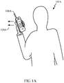
- FIGURE 1A illustrates an exemplary embodiment of the present disclosure in a handheld personal navigational device 100A according to the present disclosure.
- the device 100A is configured as a personal navigational device that determines a target location specified by the user 101A relative to a present location of the user 101A. It will be appreciated that the determination of present and target locations by a navigational device is known in the art, and may utilize, e.g., satellite signals from the global positioning system (GPS).
- GPS global positioning system
- the device 100A may generate one or more knocks or directional impulses to a side of the device 100A, as illustrated by 120A in FIGURE 1A .
- the knocks 120A are generated to the left side of the device 100A to indicate that the user should proceed to the left to reach a target location.
- FIGURE 2 illustrates an exemplary embodiment 200 of a mechanism for generating tactilely perceptible physical impulses using force induction techniques according to the present disclosure.
- a chassis 201 is provided on which the components of the mechanism 200 may be mounted.
- the chassis 201 may be, e.g., a physical chassis of a handheld device 100 as shown in FIGURE 1 .
- the chassis 201 may in turn be mounted on a separate chassis of the handheld device 100.
- the chassis 201 is coupled to a fixed mechanical support 210, which is shown as a hollow tube in FIGURE 2 .
- the tube 210 is hollow along an ordinate axis 250 (also denoted herein as a "first axis").
- a magnetic element 220 having a north pole (N) and a south pole (S) may be present inside the tube 210.
- the inside of the tube 210 may include a vacuum, and the magnetic element 220 may be constrained to move along the axis 250.
- the ordinate axis 250 is shown for descriptive purposes only, and is not meant to limit the scope of the present disclosure.
- the center of the ordinate axis may reference any arbitrary point on the tube 210.
- the interior of the tube 210 may be lined with a low-friction material, e.g., PTFE or "Teflon,” or lined with a lubricant.
- Wound around the tube 210 are one or more sets of electrically conducting wound coils, three coils 240, 241, 242 of which are shown in cross-section in FIGURE 2 . Description of the first coil 240 is given hereinbelow; it will be appreciated that similar description may apply to coils 241, 242, and any other number of coils in alternative exemplary embodiments.
- the first coil 240 is wound at least once, and preferably many times, around the tube 210.
- First 240.1 and second 240.2 ends of the first coil 240 are coupled to a current control block 218.
- Current flow is shown in FIGURE 2 with 240(a) representing current flow into the plane of the cross section, and 240(b) representing current flow out of the plane of the cross section.
- Block 218 controls the current flowing through the first coil 240.
- Coils 241 and 242 similarly have ends coupled to block 218, and may support current generated by block 218.
- Block 218 is in turn coupled to an energy source 215.
- the energy source 215 may supply the energy to generate current through any of the coils 240, 241, 242 through the current control block 218.
- the energy source 215 may also store energy generated from the coils 240, 241, 242, e.g., as further described with reference to FIGURE 5 hereinbelow.
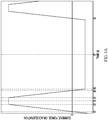
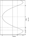
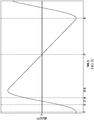
- FIGs 3A , 3B , and 3C illustrate exemplary current, displacement, and velocity profiles, respectively, for the mechanism 200 of FIGURE 2 .
- FIGURE 3A illustrates a plot of current through one or more of the coils 240, 241, 242 versus time (t), showing the progression of time from left to right along the horizontal axis. It will be appreciated that as current, force, and acceleration are expected to be proportional to one another, they are shown on a single vertical axis for simplicity.
- the displacement and velocity, respectively, of the magnetic element 220 are plotted versus time (t), assuming the corresponding current is as shown in FIGURE 3A .
- FIGs 3A , 3B , and 3C are shown for illustrative purposes only, and are not meant to limit the scope of the present disclosure to any particular current, displacement or velocity profiles shown.
- the magnetic element 220 may be understood as accelerating in the positive x direction in response to the positive current in the coil.
- a current of opposite polariy is applied, e.g., as commanded by the current control block 218.
- This change in current will be accompanied by a corresponding change in the magnetic field present in the tube 210.
- a directional impulse will be produced if the maximum acceleration of the magnetic element in one direction is greater than the maximum acceleration of the magnetic element in the other direction.
- FIGURE 3A While an exemplary current profile for only one of the coils 240, 241, and 242 is shown in FIGURE 3A , one of ordinary skill in the art will appreciate that a composite current profile may be generated by simultaneously controlling independent current profiles of all of the coils 240, 241, and 242 for the mechanism 200.
- multiple coils may be distributed along the axis of the tube 210 as shown in FIGURE 2A , and independently switched in sequence to allow finer control of the displacement profile of the magnetic element 220 over the axis of the tube 210.
- fewer or more than the three coils shown in FIGURE 2 may readily be accommodated. Such alternative exemplary embodiments are contemplated to be within the scope of the present disclosure.
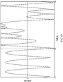
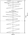
- FIGs 4A , 4B , and 4C illustrate alternative exemplary current, displacement, and velocity profiles for the mechanism 200 of FIGURE 2 .
- FIGs 4A , 4B , and 4C are shown for illustrative purposes only, and are not meant to limit the scope of the present disclosure to any particular current and/or displacement profiles shown.
- variations in the coil current during the passive interval may be harvested for energy using, e.g., a harvesting mechanism in the current control block 218 such as further described with reference to FIGURE 5 .
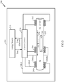
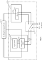
- FIGURE 5 illustrates exemplary embodiments of a current control block 218.1 and energy source 215.1 that can both generate a desired current profile during active intervals, as well as harvest energy from current during passive intervals.
- the block 218.1 includes a dual-terminal switching element 501 that selectively couples the ends 240.1 and 240.2 of a coil 240 to either an active current generation block 510 during active intervals, or to a harvesting circuit 520 during passive intervals.
- the harvesting circuit 520 may be configured to harvest electrical energy from the kinetic energy of the magnetic element 220 during passive intervals, and charge the re-chargeable energy source 215.1 with the harvested electrical energy.
- the switching element 501 is shown as switching only ends 240.1 and 240.2 for the first coil 240, it will be appreciated that a switching element may also readily accommodate additional coils 241, 242, as well as other coils not explicitly shown, according to the present disclosure.
- switching element 501 in FIGURE 5 is used only to illustrate the function of the switching element 501, and is not meant to limit the scope of the present disclosure to any particular implementation of a switching element.
- One of ordinary skill in the art will appreciate that there are a variety of ways in which such a switching element may be implemented, e.g., mechanically, or electronically using transistors and/or other circuit elements, etc. Such exemplary embodiments are contemplated to be within the scope of the present disclosure.
- the active current generation block 510 includes a logic control unit 512 for generating a digital representation 512a of a desired current profile for the coil 240 during active intervals.
- the digital representation 512a is coupled to a variable current control block 514, which may convert the digital representation 512a of the desired current to an analog current 514a, which is subsequently provided to the coil 240.
- a variable current control block 514 which may convert the digital representation 512a of the desired current to an analog current 514a, which is subsequently provided to the coil 240.
- power is drawn from the re-chargeable energy source 215.1 through circuitry controlled by the variable current control block 514 to drive the coil 240 with the analog current 514a.
- variable current control block 514 may be implemented using, e.g., a pulse-width modulation circuit for generating a current whose short-term average value corresponds to the desired current.
- the variable current control block 514 may also include, e.g., a digital-to-analog converter (DAC).
- DAC digital-to-analog converter
- the harvesting circuit 520 harvests electrical energy from the coil.
- the charging circuit is shown as including a rectifier 522 that rectifies current from the coil 240 to generate an output voltage.
- the rectifier 522 may be a bi-directional rectifier known in the art capable of rectifying both positive and negative currents.
- the output voltage 522a may be used to charge the energy source 215.1.
- the energy source 215.1 may be any re-chargeable energy source known in the art, e.g., a re-chargeable battery, a capacitor, etc.
- the harvesting circuit 520 may be implemented using any structures known to one of ordinary skill in the art to perform the functions described.
- the harvesting circuit 520 may alternatively include a voltage up-converter known in the art to generate an output voltage for the energy source 215.1.
- Such alternative exemplary embodiments are contemplated to be within the scope of the present disclosure.
- the re-chargeable energy source 215.1 may also be used to supply energy to modules of a handheld device 100 other than the mechanism 200 for generating directional force impulses.
- the mechanism 200 provides the benefits of both directional impulse generation as well as energy harvesting, which may advantageously extend the overall battery life of the handheld device 100.
- FIGURE 5 is shown for illustrative purposes only, and is not meant to limit the scope of the present disclosure to any particular implementations of the blocks shown.
- a mechanism 200 need not incorporate energy harvesting capabilities of the exemplary embodiment shown in FIGURE 5 .
- Such alternative exemplary embodiments are contemplated to be within the scope of the present disclosure.
- FIGs 6A and 6B illustrate exemplary embodiments of methods according to the present disclosure.
- the method 600A includes generating a current in at least one coil surrounding a fixed support.
- the support is coupled to a magnetic element movable along a first axis of the support.
- the current may cause the magnetic element to move along the first axis such that, over at least one cycle, the maximum acceleration of the magnetic element in one direction along the first axis is greater than the maximum acceleration of the magnetic element in the other direction along the first axis.
- the method includes harvesting energy from the at least one coil when not generating current in the at least one coil.
- the method includes storing the harvested energy in a re-chargeable energy source.
- the method 600B includes, during an active interval, generating a current in at least one coil surrounding a fixed support.
- the support is coupled to a magnetic element movable along a first axis of the support, and the current causes the magnetic element to move along the first axis.
- the method includes harvesting energy from the at least one coil and storing the harvested energy in a re-chargeable energy source.
- FIGURE 7 illustrates an alternative exemplary embodiment 700 of a mechanism for generating directional impulses according to the present disclosure.
- one or more auxiliary magnets 720, 730 may be provided at the ends of the tube 210.
- the auxiliary magnet 720 may be physically fixed at one end of the tube 210, and the auxiliary magnet 730 may be physically fixed at the other end.
- the polarity of the auxiliary magnet 720 may be chosen such that it repels the closer end of the magnetic element 220, and similarly for auxiliary magnet 730.
- the north pole (N) of the auxiliary magnet 720 is oriented toward the north pole (N) of the magnetic element 220, while the south pole (S) of the auxiliary magnet 730 is oriented toward the south pole (S) of the magnetic element 220.
- a repulsive force will be generated between the magnets 220 and 720 that will push the magnetic element 220 back towards its initial position.
- FIGURE 7 further illustrates that one or more biasing springs 710a, 710b may be provided.
- One end of the biasing spring 710a is attached to the magnetic element 220, while another end is attached to one end of the tube, e.g., to one end of the magnet 730.
- one end of the biasing spring 710b is attached to the magnetic element 220, while another end is attached to another end of the tube, e.g., to one end of the magnet 720.
- the biasing springs 710a, 710b may generate forces to pull and push the magnetic element 220 back to an initial position whenever it is displaced.
- a single magnet may be provided at the center of the tube 210 to bias the magnetic element 220 towards the center.
- Such alternative exemplary embodiments are contemplated to be within the scope of the present disclosure.
- the mechanism 700 may require the current control block 218 to generate less current in the coils 240, 241, and 242 to bring the magnet back to its initial position, thus reducing power consumption and/or the complexity of the control method.
- the one or more auxiliary magnets need not be employed in conjunction with the one or more biasing springs, and either feature can be incorporated independently of the others.
- the magnetic element 220 may specifically incorporate a non-magnetic mass (not shown) to increase the total mass of the magnetic element 220, such that the directional force impulse generated may be more clearly felt by the user.
- a non-magnetic mass may be a battery of the handheld device 100.
- more than one magnetic element 220 may also be incorporated. Such alternative exemplary embodiments are contemplated to be within the scope of the present disclosure.
- FIGURE 8A is a drawing illustrating a mobile device for providing dynamic feedback according to one embodiment.
- a mobile device 800 includes a display 802 and an input device 804.
- the mobile device 800 is a cellular phone and the input device 804 is a keypad.
- the input device 804 may also be a tracking pad, a track ball, cursor keys, or other input devices.
- the display 802 may be touch sensitive.
- the mobile device 800 includes a motion induction device 810.
- the motion induction device 810 includes a mass 812, which is accelerated within the motion induction device 810 to generate motion.
- the mass 812 may tap an object (not shown) in the motion induction device 810.
- the mass 812 is between approximately 1/16 to 1/2 ounce.
- noise may be made. For example, if the mass 812 is a magnet and the object is metallic, an audible sound is created when the mass 812 taps the object.
- a setting is available in the mobile device 800 to control the acceleration of the mass 812.
- the motion induction device 810 may be configured to accelerate the mass 812 to tap an object. If the motion induction device 810 is configured for silent mode, the mass 812 may be accelerated and decelerated to prevent tapping an object.
- the motion induction device 810 is controlled by the mobile device 800 to convey context, content, or type of messages received to a user of the mobile device 800.
- the received messages may include, for example, short text messaging (SMS) service messages, multimedia messaging service (MMS) messages, e-mail messages, voice mail messages, messages about missed calls, and messages including directions for navigation.
- the mobile device 800 may control the motion induction device 810 to notify the user of different contexts of messages by providing dynamic force feedback.
- a tapping frequency may be varied from approximately 0 to 25 Hertz. According to one embodiment as an alert becomes more urgent, the tapping frequency increases. For example, when an incoming call arrives at the mobile device 800, a first ring is at 5 Hz, a second ring is at 10 Hz, and a third ring is at 15 Hz.
- the amplitude of tapping by the motion induction device 810 may be varied by the mobile device 800.
- the acceleration of the mass 812 by the motion induction device 810 may be increased or decreased. According to one embodiment, as an alert become more urgent the tapping amplitude increases.
- the mobile device 800 may control the motion induction device 810 to convey information to the user.
- the motion induction device 810 may be controlled to tap different sequences of messages to the user.
- a tapping sequence is defined to identify an incoming caller (or group of incoming callers) without the user viewing the display 802.
- a five tap sequence may indicate a family member is calling and a three tap sequence may indicate a co-worker is calling.
- a tapping sequence is defined to identify a message type received at the mobile device 800.
- the motion induction device 810 when a short message service (SMS) message is received, the motion induction device 810 is activated to perform two short taps followed by a long tap, but when an email message is received the motion induction device 810 is activated to perform two long taps followed by a short tap.
- SMS short message service
- the mobile device 800 may control the motion induction device 810 to convey content to the user.
- the motion induction device 810 may be controlled to tap different sequences, different amplitudes, or different frequencies to convey a received message.
- a sequence of short taps with low amplitude may be a message indicating "arrived at destination safely.”
- a sequence of long taps with large amplitude may be a message indicating "lost, need directions.”
- These messages may be sent, for example, from a child to a parent to ease the parent's mind. Conveying the information without the parent viewing the display 802 increases convenience for the parent.
- the dynamic feedback provided by the motion induction device 810 provides information to the user without the user looking at the display 802.
- a wide variety of information may be conveyed by the motion induction device such as, for example, incoming call, caller id, caller group, incoming message, message type, low battery, calendar reminder, music player notifications, and position location (e.g. GPS) direction.
- Each of these alerts and additional alerts may be configured through software on the mobile device 800 through interactions with the display 802 and the input device 804. Additionally, the motion induction device 810 may consume a limited amount of power to perform acceleration of the mass 812.
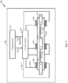
- FIGURE 8B is a drawing illustrating a mobile device for providing dynamic feedback in multiple directions according to one embodiment.
- the mobile device 800 may also include a second motion induction device 820 having a mass 822.
- the motion induction device 820 may be identical to or different from the motion induction device 810.
- the motion induction device 820 is oriented at approximately a 90 degree angle with the motion induction device 810.
- the mobile device 800 may provide dynamic feedback to the user in multiple dimensions. Although only two motion induction devices are illustrated, the mobile device 800 may include additional induction devices.
- the mobile device 800 may be configured to provide different alerts along different directions of the mobile device 800. For example, a user may be notified of an incoming email message with two horizontal taps, and the user may be notified of an incoming text message with two vertical taps.
- the multiple dimension dynamic force feedback guides the user by providing force feedback oriented in geographical directions.
- the mobile device 800 activates both motion induction devices 810, 820 to provide dynamic force feedback. For example, in navigation a user may be directed up and left by activating both motion induction devices 810, 820.
- the mobile device 800 may be configured to provide tapping dynamic feedback through the motion induction device 810 and the motion induction device 820 depending on an environment in which the mobile device 800 is located.
- FIGURE 8C is a drawing illustrating a mobile device for providing dynamic feedback and sensing the environment around the mobile device according to one embodiment.
- the mobile device 800 includes a sensor 830 such as, for example, an accelerometer, compass, inclinometer, camera, heat sensor, touch sensor, proximity sensor, or pressure sensor.
- the sensor 830 is an accelerometer for determining the orientation of the mobile device 800.
- the sensor 830 may provide other information to the mobile device 800 when selecting dynamic feedback to provide to the user.
- the senor 830 is a compass for determining the geographical orientation of the user when providing dynamic feedback for directional guidance.
- the sensor 830 is a thermometer for determining if the mobile device 800 has been placed in a user's pocket. The thermometer may provide the mobile device 800 with information about which side of the mobile device is facing the user.
- the sensor 830 is a proximity sensor for detecting whether the user is in proximity with the mobile device 800. For example, when the mobile device 800 is being held close to a user's ear, an amplitude of the motion induction devices 810, 820 may be reduced.
- FIGURE 9A is a flow chart illustrating operation of a mobile device for providing dynamic feedback in multiple dimensions according to one embodiment.
- an event occurs causing the mobile device 800 to alert the user.
- the mobile device 800 may be configured, through software, with specific events that cause the user to be alerted through dynamic force feedback.
- the mobile device 800 queries the sensor 830 to determine the orientation of the mobile device 800. If the mobile device is oriented approximately horizontal, the mobile device 800 proceeds to block 915 to provide dynamic feedback through the motion induction device 810. If the mobile device is oriented approximately vertical, the mobile device 800 proceeds to block 920 to provide dynamic feedback through the motion induction device 820.
- FIGURE 8D is a drawing illustrating a mobile device for providing dynamic feedback and sensing pressure on the mobile device according to one embodiment.
- the mobile device 800 includes a pressure sensor 832.
- the pressure sensor 832 determines how strongly a user is holding the mobile device 800.
- the mobile device 800 may change the amplitude and/or frequency of tapping provided through the motion induction device 810 and the motion induction device 820 based on information from the pressure sensor 832. For example, if a user is strongly gripping the mobile device 800, the amplitude of tapping of the motion induction device 810 and the motion induction device 820 is increased.
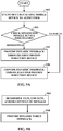
- FIGURE 9B is a flow chart illustrating operation of a mobile device for providing dynamic feedback, in another embodiment.
- a type a content, and/or a context of a message received from a remote user is determined to convey to a local user of a device.
- dynamic force feedback is provided, depending on the type, the content or the context of the message.
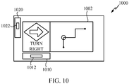
- FIGURE 10 is a drawing illustrating a mobile device for providing dynamic feedback and directions according to one embodiment.
- a navigation device 1000 includes a display 1002.
- the display 1002 may show visual directions or maps.
- the navigation device 1000 is a global positioning system (GPS) device.
- GPS global positioning system
- the navigation device 1000 also includes a motion induction device 1010 including a mass 1012 and a motion induction device 1020 including a mass 1022.
- the motion induction device 1010 is oriented approximately orthogonal to the motion induction device 1020.
- Directions may be entered into the navigation device 1000 through the display 1002 or downloaded to the navigation device 1000.
- dynamic feedback may be provided through the motion induction devices 1010, 1020.
- the motion induction device 1010 may tap right.
- the motion induction device 1010 may tap left.
- the motion induction device 1020 may tap down.
- the amplitude or frequency of the tapping provided by the motion induction devices 1010, 1020 increases as the user approaches the location where the direction should be executed. For example, as a user approaches an intersection where the user should turn right, the tapping amplitude of the motion induction devices 1010, 1020 increases.
- the navigation device 1000 is used for pedestrian navigation. For example, a user walking through a city places the navigation device 1000 in their pocket after programming directions into the navigation device 1000. As the user walks through the city the user receives tapping from the navigation device 1000 indicating which direction to walk.
- the navigation device 1000 includes a sensor for determining the orientation of the navigation device 1000 and activating the appropriate motion induction devices 1010, 1020.
- the navigation device 1000 determines an orientation from a position location receiver embedded in the navigation device 1000.
- Dynamic feedback may be useful for providing handicap assistance.
- dynamic feedback from a navigation device 1000 may be used to guide the blind.
- the dynamic feedback is incorporated into a cane, a belt, or a wrist watch.
- Providing dynamic feedback in mobile devices improves the user's experience by providing information to the user without the user viewing the display of the mobile device. For example, directions, call notification, caller id, and incoming message type may be conveyed to a user by a sequence of taps provided by motion induction devices. Additionally, tapping provided by the motion induction devices is a more natural and human-like method for getting the attention of the user. Thus, the tapping is more likely to direct the user's attention to the event occurring on the mobile device, as opposed to vibration.
- FIGURE 11 shows an exemplary wireless communication system 1100 in which an embodiment of the disclosure may be advantageously employed.
- FIGURE 11 shows three remote units 1120, 1130, and 1150 and two base stations 1140. It will be recognized that wireless communication systems may have many more remote units and base stations.
- Remote units 1120, 1130, and 1150 include motion induction devices 1125A, 1125C, and 1125B, respectively, which are embodiments as discussed above.
- FIGURE 11 shows forward link signals 1180 from the base stations 1140 and the remote units 1120, 1130, and 1150 and reverse link signals 1190 from the remote units 1120, 1130, and 1150 to base stations 1140.
- remote unit 1120 is shown as a mobile telephone
- remote unit 1130 is shown as a portable computer
- remote unit 1150 is shown as a computer in a wireless local loop system.
- the remote units may be cell phones, mobile phones, computers, set top boxes, music players, video players, entertainment units, hand-held personal communication systems (PCS) units, portable data units such as personal data assistants, or fixed location data units such as meter reading equipment.
- PCS personal communication systems
- FIGURE 11 illustrates remote units according to the teachings of the disclosure, the disclosure is not limited to these exemplary illustrated units. The disclosure may be suitably employed in any device which includes stacked ICs.
- DSP Digital Signal Processor
- ASIC Application Specific Integrated Circuit
- FPGA Field Programmable Gate Array
- a general purpose processor may be a microprocessor, but in the alternative, the processor may be any conventional processor, controller, microcontroller, or state machine.
- a processor may also be implemented as a combination of computing devices, e.g., a combination of a DSP and a microprocessor, a plurality of microprocessors, one or more microprocessors in conjunction with a DSP core, or any other such configuration.
- a software module may reside in Random Access Memory (RAM), flash memory, Read Only Memory (ROM), Electrically Programmable ROM (EPROM), Electrically Erasable Programmable ROM (EEPROM), registers, hard disk, a removable disk, a CD-ROM, or any other form of storage medium known in the art.
- An exemplary storage medium is coupled to the processor such that the processor can read information from, and write information to, the storage medium.
- the storage medium may be integral to the processor.
- the processor and the storage medium may reside in an application specific integrated circuit (ASIC).
- ASIC may reside in a user terminal.
- the processor and the storage medium may reside as discrete components in a user terminal.
- the functions described may be implemented in hardware, software, firmware, or any combination thereof. If implemented in software, the functions may be stored on or transmitted over as one or more instructions or code on a computer-readable medium.
- Computer-readable media includes both computer storage media and communication media including any medium that facilitates transfer of a computer program from one place to another.
- a storage media may be any available media that can be accessed by a computer.
- such computer-readable media can comprise RAM, ROM, EEPROM, CD-ROM or other optical disk storage, magnetic disk storage or other magnetic storage devices, or any other medium that can be used to carry or store desired program code in the form of instructions or data structures and that can be accessed by a computer.
- any connection is properly termed a computer-readable medium.
- the software is transmitted from a website, server, or other remote source using a coaxial cable, fiber optic cable, twisted pair, digital subscriber line (DSL), or wireless technologies such as infrared, radio, and microwave
- the coaxial cable, fiber optic cable, twisted pair, DSL, or wireless technologies such as infrared, radio, and microwave are included in the definition of medium.
- Disk and disc includes compact disc (CD), laser disc, optical disc, digital versatile disc (DVD), floppy disk and blu-ray disc where disks usually reproduce data magnetically, while discs reproduce data optically with lasers. Combinations of the above should also be included within the scope of computer-readable media.
Landscapes
- Engineering & Computer Science (AREA)
- General Engineering & Computer Science (AREA)
- Theoretical Computer Science (AREA)
- Human Computer Interaction (AREA)
- Physics & Mathematics (AREA)
- General Physics & Mathematics (AREA)
- Signal Processing (AREA)
- Business, Economics & Management (AREA)
- General Business, Economics & Management (AREA)
- Computer Networks & Wireless Communication (AREA)
- Computer Hardware Design (AREA)
- Telephone Function (AREA)
- User Interface Of Digital Computer (AREA)
Applications Claiming Priority (2)
| Application Number | Priority Date | Filing Date | Title |
|---|---|---|---|
| US12/940,409 US9380145B2 (en) | 2010-11-05 | 2010-11-05 | Dynamic tapping force feedback for mobile devices |
| PCT/US2011/058788 WO2012061387A1 (en) | 2010-11-05 | 2011-11-01 | Dynamic tapping force feedback for mobile devices |
Publications (2)
| Publication Number | Publication Date |
|---|---|
| EP2636213A1 EP2636213A1 (en) | 2013-09-11 |
| EP2636213B1 true EP2636213B1 (en) | 2018-02-28 |
Family
ID=45217623
Family Applications (1)
| Application Number | Title | Priority Date | Filing Date |
|---|---|---|---|
| EP11793527.0A Not-in-force EP2636213B1 (en) | 2010-11-05 | 2011-11-01 | Dynamic tapping force feedback for mobile devices |
Country Status (6)
| Country | Link |
|---|---|
| US (1) | US9380145B2 (enExample) |
| EP (1) | EP2636213B1 (enExample) |
| JP (1) | JP5960147B2 (enExample) |
| KR (1) | KR101488912B1 (enExample) |
| CN (1) | CN103262510B (enExample) |
| WO (1) | WO2012061387A1 (enExample) |
Families Citing this family (22)
| Publication number | Priority date | Publication date | Assignee | Title |
|---|---|---|---|---|
| US8487759B2 (en) | 2009-09-30 | 2013-07-16 | Apple Inc. | Self adapting haptic device |
| US8775044B2 (en) | 2011-06-08 | 2014-07-08 | Ford Global Technologies, Llc | Clutch torque trajectory correction to provide torque hole filling during a ratio upshift |
| CN103856616B (zh) * | 2012-12-03 | 2016-08-17 | 联想(北京)有限公司 | 一种提示信息生成方法及电子设备 |
| US10504339B2 (en) | 2013-02-21 | 2019-12-10 | Immersion Corporation | Mobile device with instinctive alerts |
| WO2015047372A1 (en) | 2013-09-30 | 2015-04-02 | Pearl Capital Developments Llc | Magnetic actuators for haptic response |
| US9317118B2 (en) | 2013-10-22 | 2016-04-19 | Apple Inc. | Touch surface for simulating materials |
| AU2014391723B2 (en) | 2014-04-21 | 2018-04-05 | Apple Inc. | Apportionment of forces for multi-touch input devices of electronic devices |
| US9830782B2 (en) | 2014-09-02 | 2017-11-28 | Apple Inc. | Haptic notifications |
| US10353467B2 (en) | 2015-03-06 | 2019-07-16 | Apple Inc. | Calibration of haptic devices |
| AU2016100399B4 (en) | 2015-04-17 | 2017-02-02 | Apple Inc. | Contracting and elongating materials for providing input and output for an electronic device |
| US9912364B2 (en) * | 2015-06-25 | 2018-03-06 | International Business Machines Corporation | Mobile application interaction guide via tactile feedback |
| CN107925333B (zh) | 2015-09-08 | 2020-10-23 | 苹果公司 | 用于在电子设备中使用的线性致动器 |
| CN105511628A (zh) * | 2015-12-25 | 2016-04-20 | 魅族科技(中国)有限公司 | 一种对马达进行控制的方法及终端 |
| CN108697168A (zh) * | 2016-03-02 | 2018-10-23 | 菲利普莫里斯生产公司 | 包括反馈装置的气溶胶生成装置 |
| US10039080B2 (en) | 2016-03-04 | 2018-07-31 | Apple Inc. | Situationally-aware alerts |
| US10268272B2 (en) | 2016-03-31 | 2019-04-23 | Apple Inc. | Dampening mechanical modes of a haptic actuator using a delay |
| US10622538B2 (en) | 2017-07-18 | 2020-04-14 | Apple Inc. | Techniques for providing a haptic output and sensing a haptic input using a piezoelectric body |
| US10599223B1 (en) | 2018-09-28 | 2020-03-24 | Apple Inc. | Button providing force sensing and/or haptic output |
| US10691211B2 (en) | 2018-09-28 | 2020-06-23 | Apple Inc. | Button providing force sensing and/or haptic output |
| US11380470B2 (en) | 2019-09-24 | 2022-07-05 | Apple Inc. | Methods to control force in reluctance actuators based on flux related parameters |
| US11977683B2 (en) | 2021-03-12 | 2024-05-07 | Apple Inc. | Modular systems configured to provide localized haptic feedback using inertial actuators |
| US11809631B2 (en) | 2021-09-21 | 2023-11-07 | Apple Inc. | Reluctance haptic engine for an electronic device |
Citations (1)
| Publication number | Priority date | Publication date | Assignee | Title |
|---|---|---|---|---|
| US20100273469A1 (en) * | 2007-12-17 | 2010-10-28 | Gemalto Sa | Warning system for signaling the presence of a radio frequency communication and manufacturing method |
Family Cites Families (28)
| Publication number | Priority date | Publication date | Assignee | Title |
|---|---|---|---|---|
| JPH10313933A (ja) | 1997-05-20 | 1998-12-02 | Matsushita Electric Ind Co Ltd | 携帯型電子機器用発電装置及び該発電装置を備えた携帯型電子機器 |
| JP2000042491A (ja) | 1998-07-31 | 2000-02-15 | Matsushita Electric Ind Co Ltd | 振動による報知装置 |
| US7159008B1 (en) | 2000-06-30 | 2007-01-02 | Immersion Corporation | Chat interface with haptic feedback functionality |
| JP2003083762A (ja) | 2001-09-13 | 2003-03-19 | Sony Corp | 目的地案内装置、方法、プログラムおよび該プログラムを記録した記録媒体 |
| JP2003288158A (ja) | 2002-01-28 | 2003-10-10 | Sony Corp | タクタイル・フィードバック機能を持つ携帯型機器 |
| US20060136630A1 (en) | 2002-12-08 | 2006-06-22 | Immersion Corporation, A Delaware Corporation | Methods and systems for providing haptic messaging to handheld communication devices |
| US20040214594A1 (en) * | 2003-04-28 | 2004-10-28 | Motorola, Inc. | Device having smart user alert |
| US7194099B2 (en) | 2003-06-10 | 2007-03-20 | Motorola, Inc. | Handheld electronics devices with multiple user sensory transducers and methods |
| US20060066569A1 (en) | 2003-12-08 | 2006-03-30 | Immersion Corporation, A Delaware Corporation | Methods and systems for providing haptic messaging to handheld communication devices |
| JP4278506B2 (ja) | 2003-12-26 | 2009-06-17 | シャープ株式会社 | 携帯通信端末、携帯通信端末の着信通知方法、およびその方法を実現するためのプログラム |
| JP2006075734A (ja) | 2004-09-09 | 2006-03-23 | Namiki Precision Jewel Co Ltd | 偏平振動アクチュエータ |
| KR100568315B1 (ko) | 2004-09-24 | 2006-04-05 | 삼성전기주식회사 | 통신단말기용 멀티 모드 진동발생장치 |
| EP1803170B1 (en) * | 2004-10-21 | 2011-06-22 | Société de Technologie Michelin | Energy harvester with adjustable resonant frequency |
| US7469155B2 (en) * | 2004-11-29 | 2008-12-23 | Cisco Technology, Inc. | Handheld communications device with automatic alert mode selection |
| US20060248183A1 (en) | 2005-04-28 | 2006-11-02 | Microsoft Corporation | Programmable notifications for a mobile device |
| JP2007166450A (ja) | 2005-12-16 | 2007-06-28 | Nec Corp | 携帯装置及び携帯装置での入力方法 |
| US20080001484A1 (en) | 2006-07-03 | 2008-01-03 | Chris Fuller | Linear Electromechanical Vibrator with Axially Movable Magnet |
| JP2008066966A (ja) | 2006-09-06 | 2008-03-21 | Canon Inc | 光学機器 |
| US7890863B2 (en) | 2006-10-04 | 2011-02-15 | Immersion Corporation | Haptic effects with proximity sensing |
| JP5508684B2 (ja) | 2007-03-13 | 2014-06-04 | 国立大学法人信州大学 | リニア振動アクチュエータとそれを用いたリニアコンプレッサーおよびリニア振動発電機 |
| US7801569B1 (en) * | 2007-03-22 | 2010-09-21 | At&T Intellectual Property I, L.P. | Mobile communications device with distinctive vibration modes |
| US8315652B2 (en) | 2007-05-18 | 2012-11-20 | Immersion Corporation | Haptically enabled messaging |
| US7788032B2 (en) * | 2007-09-14 | 2010-08-31 | Palm, Inc. | Targeting location through haptic feedback signals |
| KR101474426B1 (ko) | 2008-01-22 | 2014-12-19 | 엘지전자 주식회사 | 이동 단말기 및 그의 진동 모터 제어 방법 |
| US20090280860A1 (en) * | 2008-05-12 | 2009-11-12 | Sony Ericsson Mobile Communications Ab | Mobile phone with directional force feedback and method |
| US8306576B2 (en) * | 2008-06-27 | 2012-11-06 | Lg Electronics Inc. | Mobile terminal capable of providing haptic effect and method of controlling the mobile terminal |
| EP2406699A1 (en) | 2009-03-10 | 2012-01-18 | Bayer MaterialScience AG | Electroactive polymer transducers for tactile feedback devices |
| KR101553842B1 (ko) | 2009-04-21 | 2015-09-17 | 엘지전자 주식회사 | 멀티 햅틱 효과를 제공하는 휴대 단말기 및 그 제어방법 |
-
2010
- 2010-11-05 US US12/940,409 patent/US9380145B2/en active Active
-
2011
- 2011-11-01 JP JP2013537765A patent/JP5960147B2/ja not_active Expired - Fee Related
- 2011-11-01 CN CN201180060226.5A patent/CN103262510B/zh not_active Expired - Fee Related
- 2011-11-01 WO PCT/US2011/058788 patent/WO2012061387A1/en not_active Ceased
- 2011-11-01 EP EP11793527.0A patent/EP2636213B1/en not_active Not-in-force
- 2011-11-01 KR KR1020137013204A patent/KR101488912B1/ko not_active Expired - Fee Related
Patent Citations (1)
| Publication number | Priority date | Publication date | Assignee | Title |
|---|---|---|---|---|
| US20100273469A1 (en) * | 2007-12-17 | 2010-10-28 | Gemalto Sa | Warning system for signaling the presence of a radio frequency communication and manufacturing method |
Also Published As
| Publication number | Publication date |
|---|---|
| CN103262510A (zh) | 2013-08-21 |
| US20120115445A1 (en) | 2012-05-10 |
| KR20130086616A (ko) | 2013-08-02 |
| WO2012061387A1 (en) | 2012-05-10 |
| US9380145B2 (en) | 2016-06-28 |
| EP2636213A1 (en) | 2013-09-11 |
| CN103262510B (zh) | 2015-11-25 |
| JP5960147B2 (ja) | 2016-08-02 |
| KR101488912B1 (ko) | 2015-02-02 |
| JP2014500659A (ja) | 2014-01-09 |
Similar Documents
| Publication | Publication Date | Title |
|---|---|---|
| EP2636213B1 (en) | Dynamic tapping force feedback for mobile devices | |
| US8901783B2 (en) | Handheld device force induction | |
| US9558475B2 (en) | Location based to-do list reminders | |
| US9531235B2 (en) | Dynamic center of mass | |
| CN102823145B (zh) | 用于确定交互模式的方法和设备 | |
| CN102281348B (zh) | 使用增强现实引导路线的方法以及使用该方法的移动终端 | |
| US20020193150A1 (en) | System and method for providing location-based responses | |
| US20160241119A1 (en) | Vibration Component that Harvests Energy for Electronic Devices | |
| US20080252594A1 (en) | Vibration Actuator with a Unidirectional Drive | |
| WO2007033236A2 (en) | Methods and systems for providing haptic messaging to handheld communication device | |
| EP2049975A2 (en) | Pointing device with moveable magnetic disc and method | |
| US9774289B2 (en) | Method for driving vibrating motor | |
| KR20080092463A (ko) | 휴대 전자기기와 그 방위 표시 방법 | |
| JP4228253B2 (ja) | 歩数計 | |
| EP1934765A2 (en) | Methods and systems for providing haptic messaging to handheld communication devices | |
| US9818272B2 (en) | Electronic device including sound level based driving of haptic actuator and related methods | |
| KR102011771B1 (ko) | 사용자 인터페이스 제공 방법 및 그 장치 | |
| JP2014154901A (ja) | 携帯電子機器、その制御方法及びプログラム | |
| KR20050080636A (ko) | 안테나를 이용하여 충전하는 이동통신단말기 | |
| KR20070056263A (ko) | 하차 위치 통지 기능을 구비한 휴대용 단말기 |
Legal Events
| Date | Code | Title | Description |
|---|---|---|---|
| PUAI | Public reference made under article 153(3) epc to a published international application that has entered the european phase |
Free format text: ORIGINAL CODE: 0009012 |
|
| 17P | Request for examination filed |
Effective date: 20130415 |
|
| AK | Designated contracting states |
Kind code of ref document: A1 Designated state(s): AL AT BE BG CH CY CZ DE DK EE ES FI FR GB GR HR HU IE IS IT LI LT LU LV MC MK MT NL NO PL PT RO RS SE SI SK SM TR |
|
| DAX | Request for extension of the european patent (deleted) | ||
| 17Q | First examination report despatched |
Effective date: 20161208 |
|
| GRAP | Despatch of communication of intention to grant a patent |
Free format text: ORIGINAL CODE: EPIDOSNIGR1 |
|
| INTG | Intention to grant announced |
Effective date: 20170927 |
|
| RAP1 | Party data changed (applicant data changed or rights of an application transferred) |
Owner name: QUALCOMM INCORPORATED |
|
| GRAS | Grant fee paid |
Free format text: ORIGINAL CODE: EPIDOSNIGR3 |
|
| GRAA | (expected) grant |
Free format text: ORIGINAL CODE: 0009210 |
|
| AK | Designated contracting states |
Kind code of ref document: B1 Designated state(s): AL AT BE BG CH CY CZ DE DK EE ES FI FR GB GR HR HU IE IS IT LI LT LU LV MC MK MT NL NO PL PT RO RS SE SI SK SM TR |
|
| REG | Reference to a national code |
Ref country code: GB Ref legal event code: FG4D Ref country code: CH Ref legal event code: EP |
|
| REG | Reference to a national code |
Ref country code: AT Ref legal event code: REF Ref document number: 975346 Country of ref document: AT Kind code of ref document: T Effective date: 20180315 |
|
| REG | Reference to a national code |
Ref country code: IE Ref legal event code: FG4D |
|
| REG | Reference to a national code |
Ref country code: DE Ref legal event code: R096 Ref document number: 602011046084 Country of ref document: DE |
|
| REG | Reference to a national code |
Ref country code: NL Ref legal event code: MP Effective date: 20180228 |
|
| REG | Reference to a national code |
Ref country code: LT Ref legal event code: MG4D |
|
| REG | Reference to a national code |
Ref country code: AT Ref legal event code: MK05 Ref document number: 975346 Country of ref document: AT Kind code of ref document: T Effective date: 20180228 |
|
| PG25 | Lapsed in a contracting state [announced via postgrant information from national office to epo] |
Ref country code: ES Free format text: LAPSE BECAUSE OF FAILURE TO SUBMIT A TRANSLATION OF THE DESCRIPTION OR TO PAY THE FEE WITHIN THE PRESCRIBED TIME-LIMIT Effective date: 20180228 Ref country code: LT Free format text: LAPSE BECAUSE OF FAILURE TO SUBMIT A TRANSLATION OF THE DESCRIPTION OR TO PAY THE FEE WITHIN THE PRESCRIBED TIME-LIMIT Effective date: 20180228 Ref country code: NL Free format text: LAPSE BECAUSE OF FAILURE TO SUBMIT A TRANSLATION OF THE DESCRIPTION OR TO PAY THE FEE WITHIN THE PRESCRIBED TIME-LIMIT Effective date: 20180228 Ref country code: CY Free format text: LAPSE BECAUSE OF FAILURE TO SUBMIT A TRANSLATION OF THE DESCRIPTION OR TO PAY THE FEE WITHIN THE PRESCRIBED TIME-LIMIT Effective date: 20180228 Ref country code: HR Free format text: LAPSE BECAUSE OF FAILURE TO SUBMIT A TRANSLATION OF THE DESCRIPTION OR TO PAY THE FEE WITHIN THE PRESCRIBED TIME-LIMIT Effective date: 20180228 Ref country code: NO Free format text: LAPSE BECAUSE OF FAILURE TO SUBMIT A TRANSLATION OF THE DESCRIPTION OR TO PAY THE FEE WITHIN THE PRESCRIBED TIME-LIMIT Effective date: 20180528 Ref country code: FI Free format text: LAPSE BECAUSE OF FAILURE TO SUBMIT A TRANSLATION OF THE DESCRIPTION OR TO PAY THE FEE WITHIN THE PRESCRIBED TIME-LIMIT Effective date: 20180228 |
|
| PG25 | Lapsed in a contracting state [announced via postgrant information from national office to epo] |
Ref country code: BG Free format text: LAPSE BECAUSE OF FAILURE TO SUBMIT A TRANSLATION OF THE DESCRIPTION OR TO PAY THE FEE WITHIN THE PRESCRIBED TIME-LIMIT Effective date: 20180528 Ref country code: GR Free format text: LAPSE BECAUSE OF FAILURE TO SUBMIT A TRANSLATION OF THE DESCRIPTION OR TO PAY THE FEE WITHIN THE PRESCRIBED TIME-LIMIT Effective date: 20180529 Ref country code: SE Free format text: LAPSE BECAUSE OF FAILURE TO SUBMIT A TRANSLATION OF THE DESCRIPTION OR TO PAY THE FEE WITHIN THE PRESCRIBED TIME-LIMIT Effective date: 20180228 Ref country code: LV Free format text: LAPSE BECAUSE OF FAILURE TO SUBMIT A TRANSLATION OF THE DESCRIPTION OR TO PAY THE FEE WITHIN THE PRESCRIBED TIME-LIMIT Effective date: 20180228 Ref country code: AT Free format text: LAPSE BECAUSE OF FAILURE TO SUBMIT A TRANSLATION OF THE DESCRIPTION OR TO PAY THE FEE WITHIN THE PRESCRIBED TIME-LIMIT Effective date: 20180228 Ref country code: RS Free format text: LAPSE BECAUSE OF FAILURE TO SUBMIT A TRANSLATION OF THE DESCRIPTION OR TO PAY THE FEE WITHIN THE PRESCRIBED TIME-LIMIT Effective date: 20180228 |
|
| PG25 | Lapsed in a contracting state [announced via postgrant information from national office to epo] |
Ref country code: PL Free format text: LAPSE BECAUSE OF FAILURE TO SUBMIT A TRANSLATION OF THE DESCRIPTION OR TO PAY THE FEE WITHIN THE PRESCRIBED TIME-LIMIT Effective date: 20180228 Ref country code: AL Free format text: LAPSE BECAUSE OF FAILURE TO SUBMIT A TRANSLATION OF THE DESCRIPTION OR TO PAY THE FEE WITHIN THE PRESCRIBED TIME-LIMIT Effective date: 20180228 Ref country code: IT Free format text: LAPSE BECAUSE OF FAILURE TO SUBMIT A TRANSLATION OF THE DESCRIPTION OR TO PAY THE FEE WITHIN THE PRESCRIBED TIME-LIMIT Effective date: 20180228 Ref country code: RO Free format text: LAPSE BECAUSE OF FAILURE TO SUBMIT A TRANSLATION OF THE DESCRIPTION OR TO PAY THE FEE WITHIN THE PRESCRIBED TIME-LIMIT Effective date: 20180228 Ref country code: EE Free format text: LAPSE BECAUSE OF FAILURE TO SUBMIT A TRANSLATION OF THE DESCRIPTION OR TO PAY THE FEE WITHIN THE PRESCRIBED TIME-LIMIT Effective date: 20180228 |
|
| REG | Reference to a national code |
Ref country code: DE Ref legal event code: R097 Ref document number: 602011046084 Country of ref document: DE |
|
| PG25 | Lapsed in a contracting state [announced via postgrant information from national office to epo] |
Ref country code: DK Free format text: LAPSE BECAUSE OF FAILURE TO SUBMIT A TRANSLATION OF THE DESCRIPTION OR TO PAY THE FEE WITHIN THE PRESCRIBED TIME-LIMIT Effective date: 20180228 Ref country code: CZ Free format text: LAPSE BECAUSE OF FAILURE TO SUBMIT A TRANSLATION OF THE DESCRIPTION OR TO PAY THE FEE WITHIN THE PRESCRIBED TIME-LIMIT Effective date: 20180228 Ref country code: SM Free format text: LAPSE BECAUSE OF FAILURE TO SUBMIT A TRANSLATION OF THE DESCRIPTION OR TO PAY THE FEE WITHIN THE PRESCRIBED TIME-LIMIT Effective date: 20180228 Ref country code: SK Free format text: LAPSE BECAUSE OF FAILURE TO SUBMIT A TRANSLATION OF THE DESCRIPTION OR TO PAY THE FEE WITHIN THE PRESCRIBED TIME-LIMIT Effective date: 20180228 |
|
| PLBE | No opposition filed within time limit |
Free format text: ORIGINAL CODE: 0009261 |
|
| STAA | Information on the status of an ep patent application or granted ep patent |
Free format text: STATUS: NO OPPOSITION FILED WITHIN TIME LIMIT |
|
| 26N | No opposition filed |
Effective date: 20181129 |
|
| PG25 | Lapsed in a contracting state [announced via postgrant information from national office to epo] |
Ref country code: SI Free format text: LAPSE BECAUSE OF FAILURE TO SUBMIT A TRANSLATION OF THE DESCRIPTION OR TO PAY THE FEE WITHIN THE PRESCRIBED TIME-LIMIT Effective date: 20180228 |
|
| REG | Reference to a national code |
Ref country code: DE Ref legal event code: R119 Ref document number: 602011046084 Country of ref document: DE |
|
| REG | Reference to a national code |
Ref country code: CH Ref legal event code: PL |
|
| GBPC | Gb: european patent ceased through non-payment of renewal fee |
Effective date: 20181101 |
|
| PG25 | Lapsed in a contracting state [announced via postgrant information from national office to epo] |
Ref country code: LU Free format text: LAPSE BECAUSE OF NON-PAYMENT OF DUE FEES Effective date: 20181101 Ref country code: MC Free format text: LAPSE BECAUSE OF FAILURE TO SUBMIT A TRANSLATION OF THE DESCRIPTION OR TO PAY THE FEE WITHIN THE PRESCRIBED TIME-LIMIT Effective date: 20180228 |
|
| REG | Reference to a national code |
Ref country code: BE Ref legal event code: MM Effective date: 20181130 |
|
| REG | Reference to a national code |
Ref country code: IE Ref legal event code: MM4A |
|
| PG25 | Lapsed in a contracting state [announced via postgrant information from national office to epo] |
Ref country code: CH Free format text: LAPSE BECAUSE OF NON-PAYMENT OF DUE FEES Effective date: 20181130 Ref country code: LI Free format text: LAPSE BECAUSE OF NON-PAYMENT OF DUE FEES Effective date: 20181130 |
|
| PG25 | Lapsed in a contracting state [announced via postgrant information from national office to epo] |
Ref country code: IE Free format text: LAPSE BECAUSE OF NON-PAYMENT OF DUE FEES Effective date: 20181101 Ref country code: DE Free format text: LAPSE BECAUSE OF NON-PAYMENT OF DUE FEES Effective date: 20190601 Ref country code: FR Free format text: LAPSE BECAUSE OF NON-PAYMENT OF DUE FEES Effective date: 20181130 |
|
| PG25 | Lapsed in a contracting state [announced via postgrant information from national office to epo] |
Ref country code: BE Free format text: LAPSE BECAUSE OF NON-PAYMENT OF DUE FEES Effective date: 20181130 |
|
| PG25 | Lapsed in a contracting state [announced via postgrant information from national office to epo] |
Ref country code: GB Free format text: LAPSE BECAUSE OF NON-PAYMENT OF DUE FEES Effective date: 20181101 |
|
| PG25 | Lapsed in a contracting state [announced via postgrant information from national office to epo] |
Ref country code: MT Free format text: LAPSE BECAUSE OF NON-PAYMENT OF DUE FEES Effective date: 20181101 |
|
| PG25 | Lapsed in a contracting state [announced via postgrant information from national office to epo] |
Ref country code: TR Free format text: LAPSE BECAUSE OF FAILURE TO SUBMIT A TRANSLATION OF THE DESCRIPTION OR TO PAY THE FEE WITHIN THE PRESCRIBED TIME-LIMIT Effective date: 20180228 |
|
| PG25 | Lapsed in a contracting state [announced via postgrant information from national office to epo] |
Ref country code: PT Free format text: LAPSE BECAUSE OF FAILURE TO SUBMIT A TRANSLATION OF THE DESCRIPTION OR TO PAY THE FEE WITHIN THE PRESCRIBED TIME-LIMIT Effective date: 20180228 |
|
| PG25 | Lapsed in a contracting state [announced via postgrant information from national office to epo] |
Ref country code: MK Free format text: LAPSE BECAUSE OF NON-PAYMENT OF DUE FEES Effective date: 20180228 Ref country code: HU Free format text: LAPSE BECAUSE OF FAILURE TO SUBMIT A TRANSLATION OF THE DESCRIPTION OR TO PAY THE FEE WITHIN THE PRESCRIBED TIME-LIMIT; INVALID AB INITIO Effective date: 20111101 |
|
| PG25 | Lapsed in a contracting state [announced via postgrant information from national office to epo] |
Ref country code: IS Free format text: LAPSE BECAUSE OF FAILURE TO SUBMIT A TRANSLATION OF THE DESCRIPTION OR TO PAY THE FEE WITHIN THE PRESCRIBED TIME-LIMIT Effective date: 20180628 |